Comparison of Forced Convective Heat-Transfer Enhancement of Conventional and Thin Plate-Fin Heat Sinks under Sinusoidal Vibration


Abstract
:1. Introduction
2. Methodology
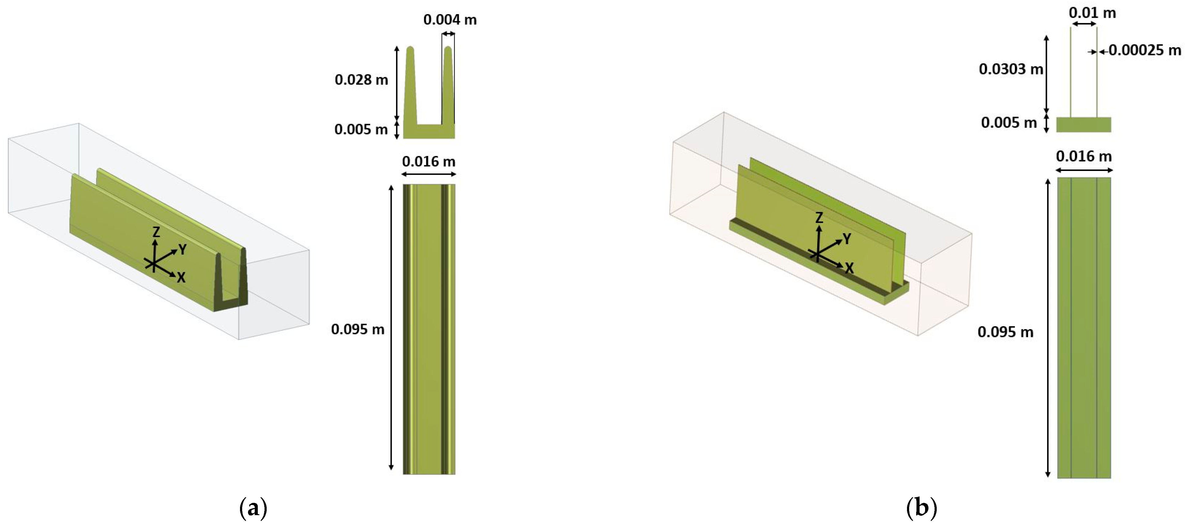
2.1. Problem Description
2.2. Governing Equations
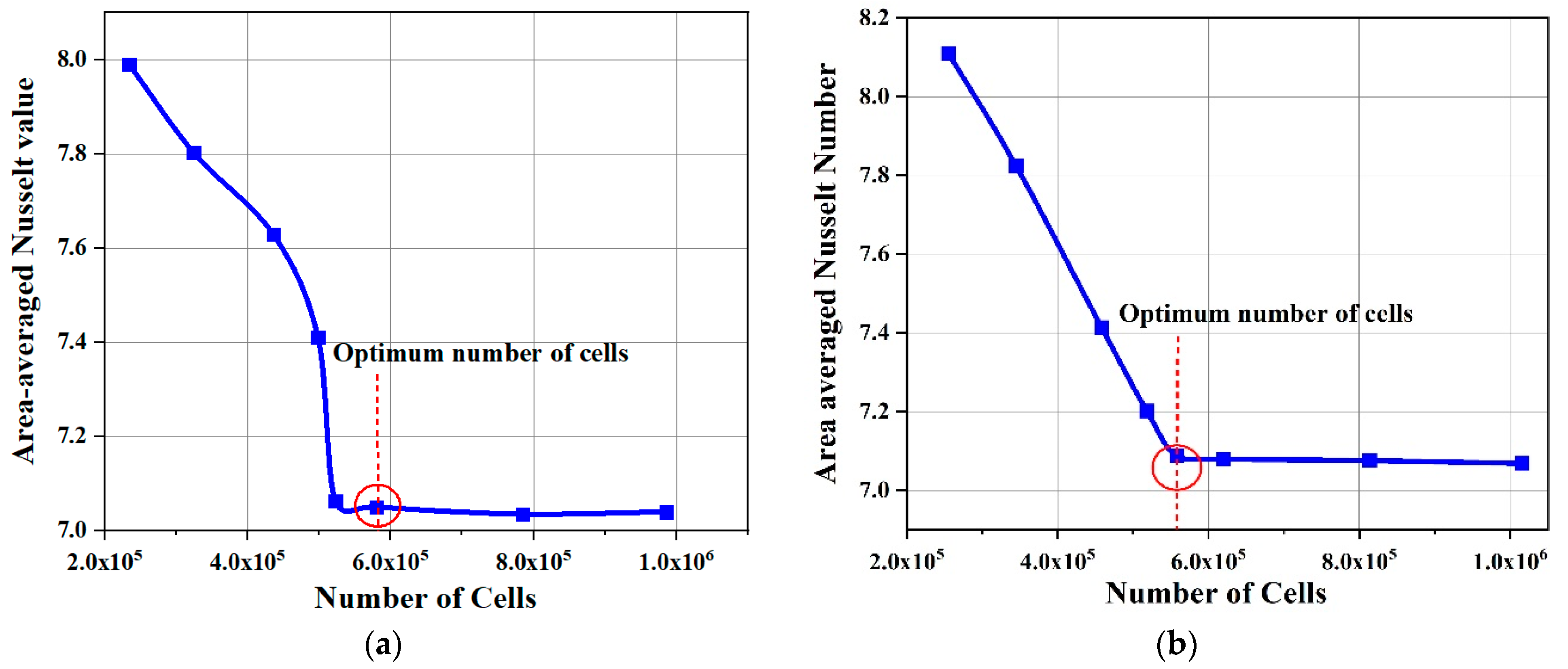
2.3. Computational Details
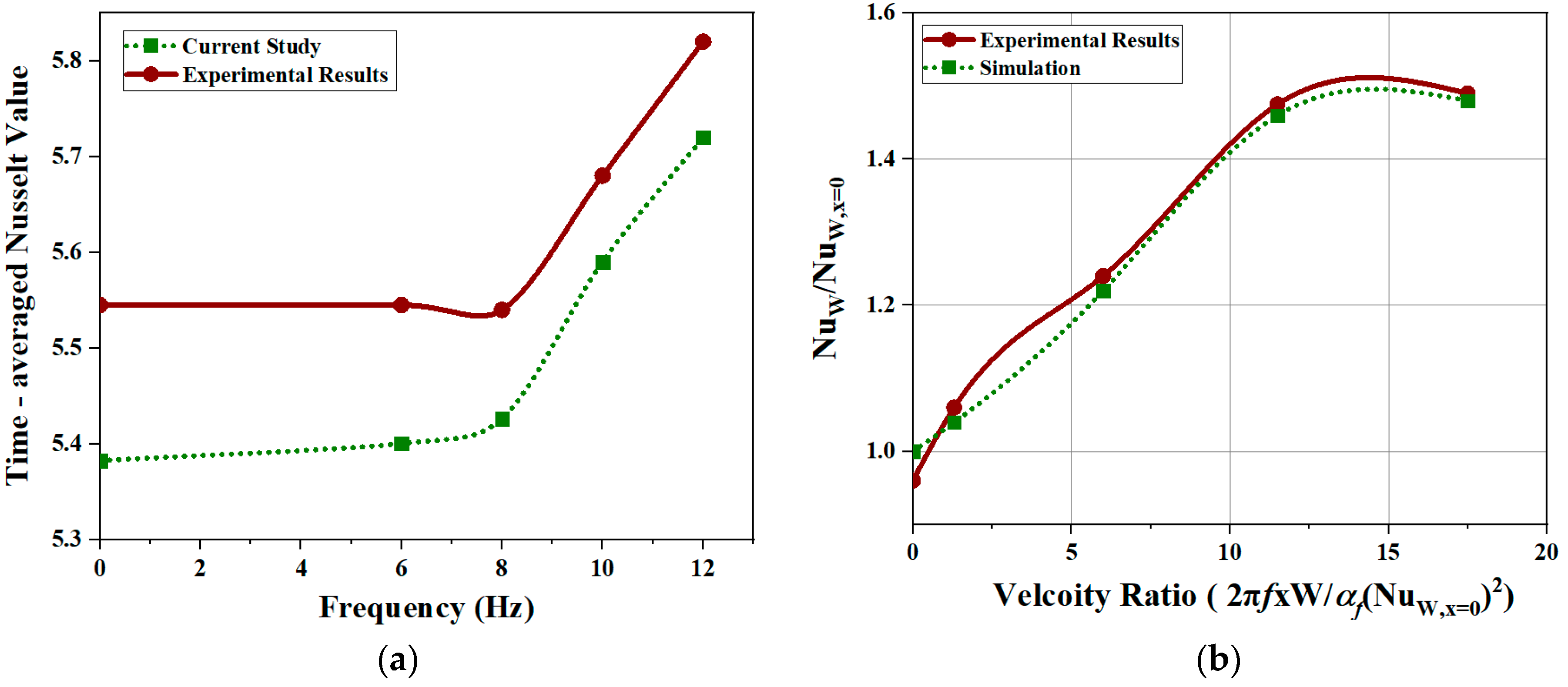
2.4. Validation
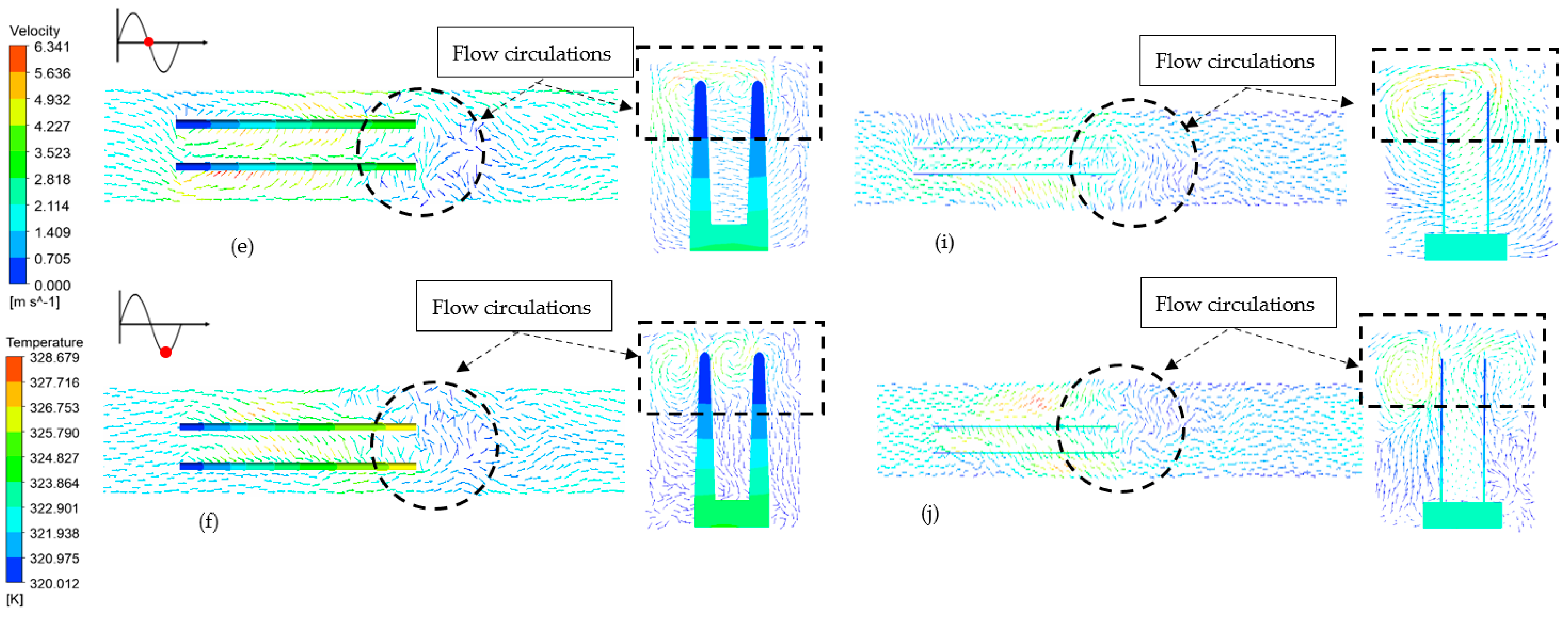
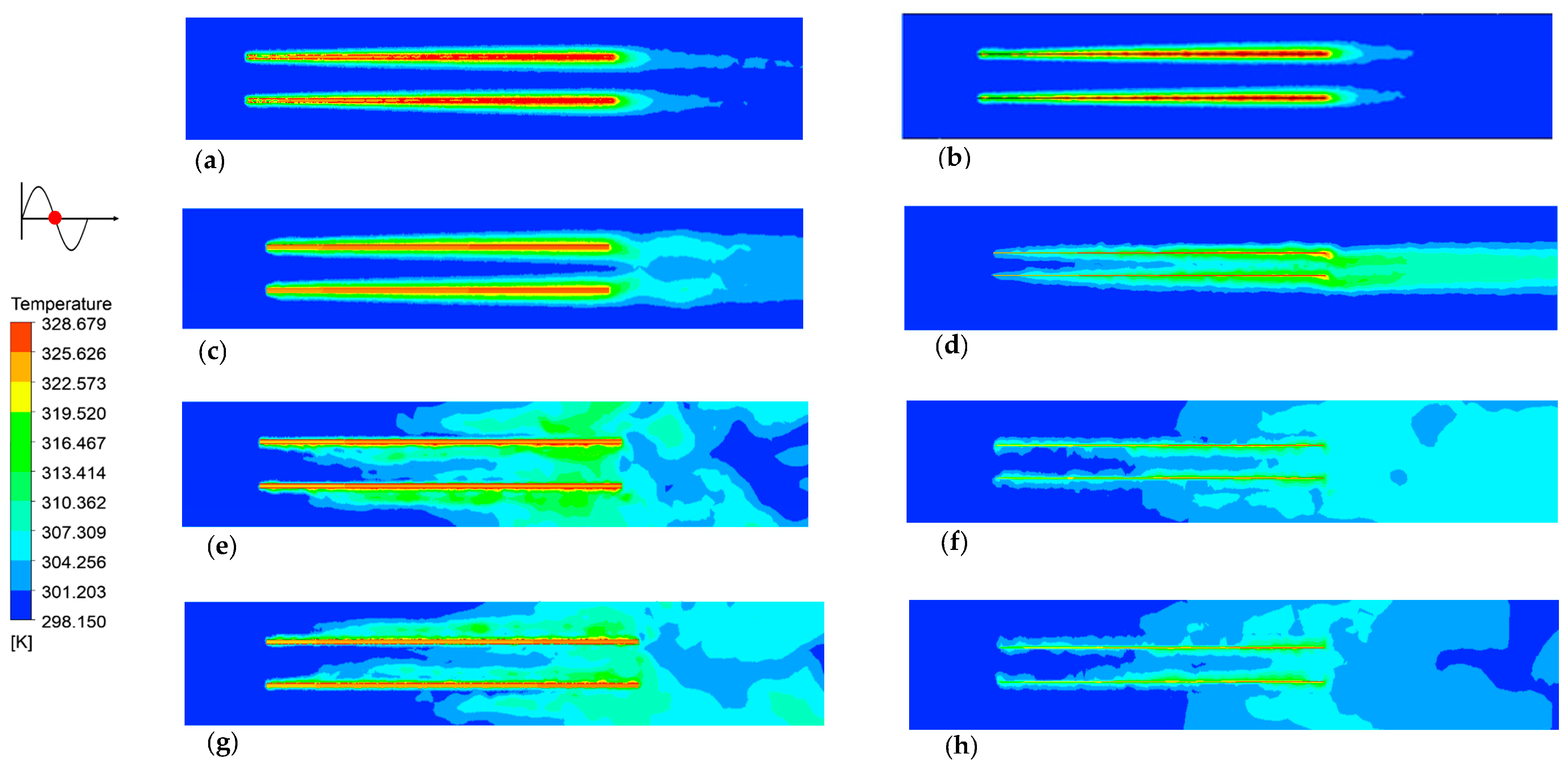
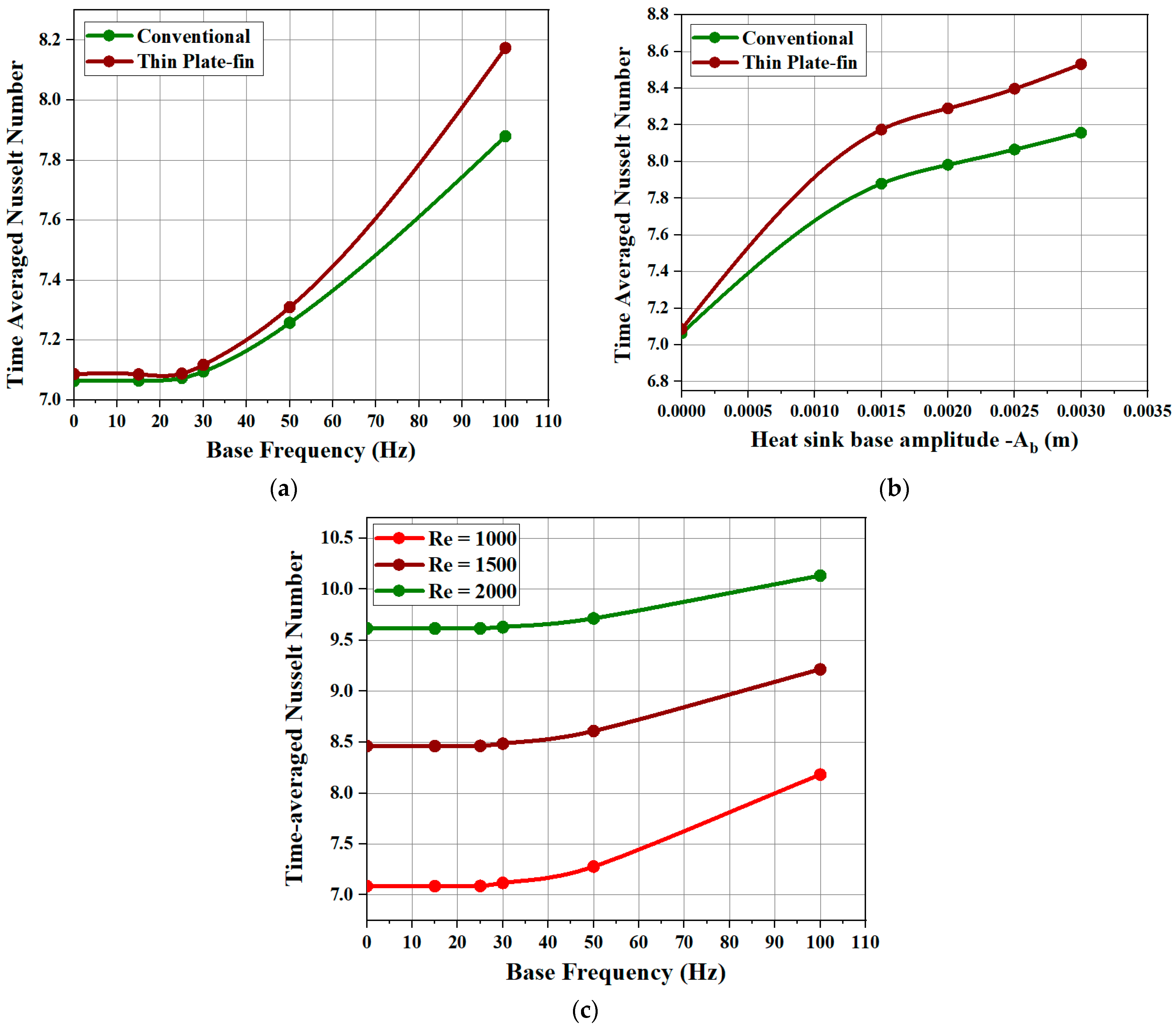
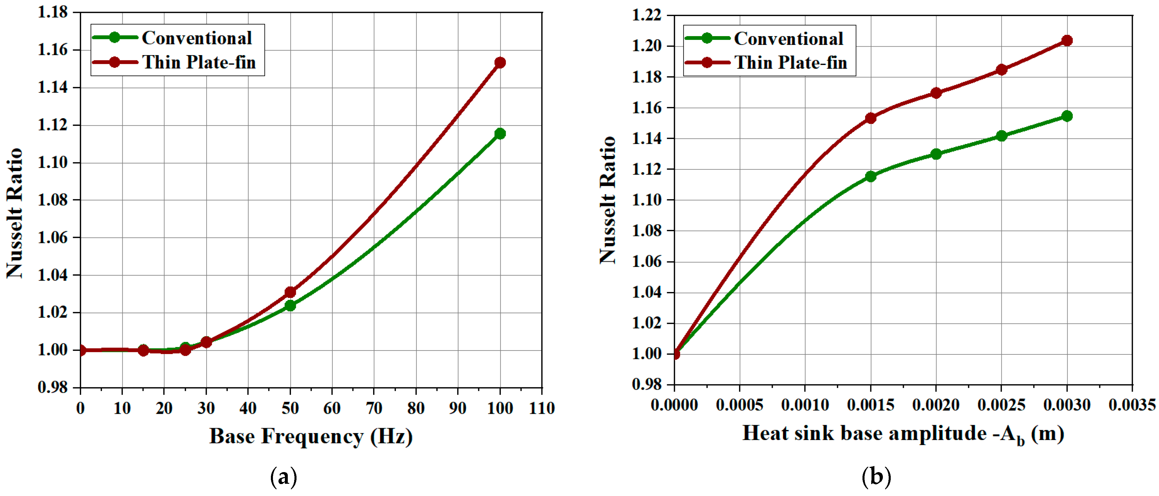
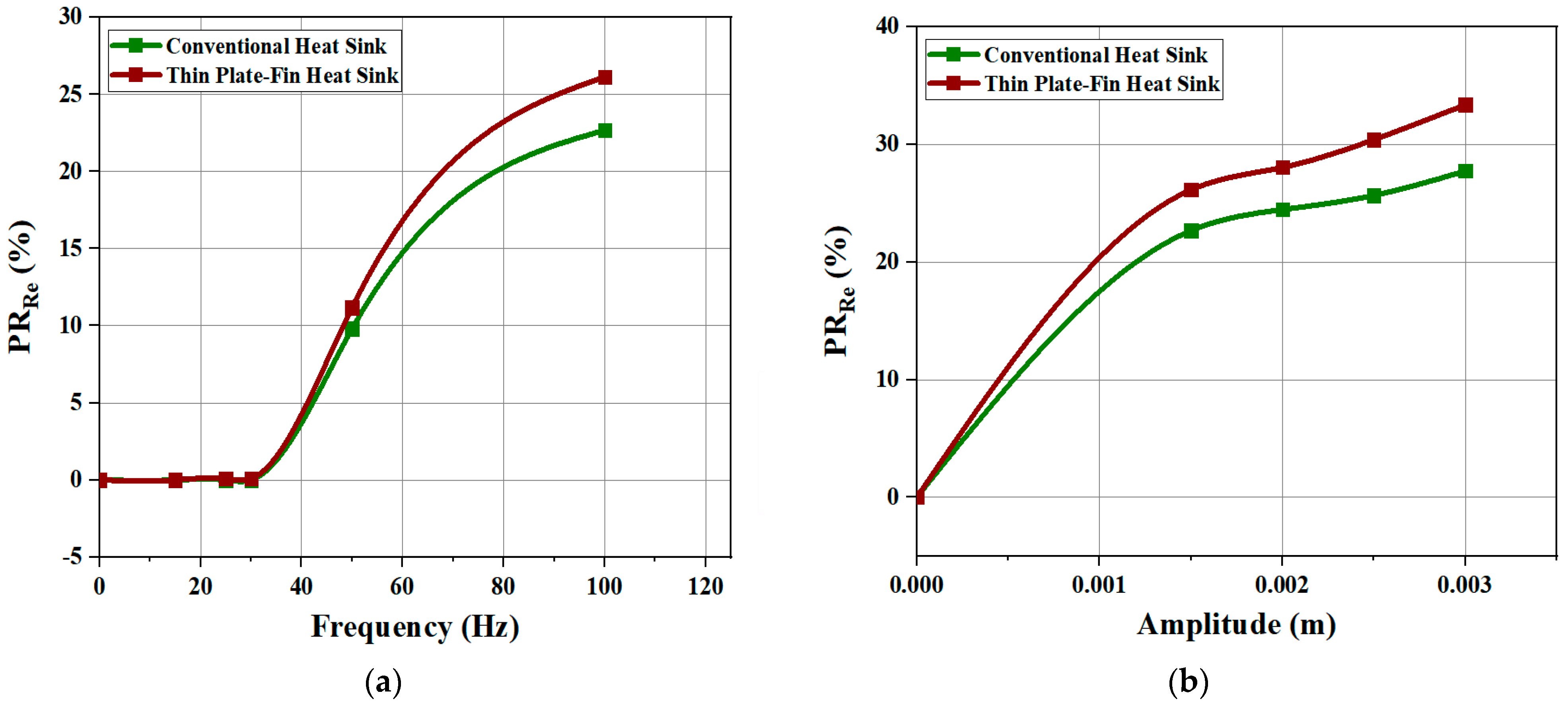
3. Results
4. Conclusions
Author Contributions
Funding
Institutional Review Board Statement
Informed Consent Statement
Data Availability Statement
Acknowledgments
Conflicts of Interest
Nomenclature and Abbreviations
| Nomenclature | ||
| Ab | Base amplitude (m) | |
| b | Fin spacing (m) | |
| Cp | Constant specific heat (J/(kg K)) | |
| f | Vibrational frequency (Hz) | |
| fn | Natural frequency of thin fin (Hz) | |
| H | Height of the fins (m) | |
| k | Thermal conductivity of fluid (W/(m K)) | |
| L | Length of the fins (m) | |
| Nuwithout | Nusselt number of heat sink in the no-vibration conditions | |
| Nuwith | Nusselt number of heat sink at vibration conditions | |
| P | Hydrostatic pressure (Pa) | |
| Pr | Prandtl number | |
| Re | Reynolds number (ρUb/µ) | |
| T | Temperature (K) | |
| t | Time (s) | |
| Ui | Velocity in ith direction (m/s) | |
| Xi | Cartesian coordinates (m) | |
| Y | Horizontal displacement at any time (m) | |
| Z | Height between any point on the fin to the base of the fin (m) | |
| Greek Symbols | ||
| µ | Fluid viscosity (Pa.s) | |
| ρ | Fluid density (Kg/m3) | |
| τ | Cycle time (s) | |
| ∆t | Time step (s) | |
| α | Thermal diffusivity of the fin material (m2/s) | |
| τij | Sub-grid scale stress (Pa) | |
| λ | The solutions of the equation cos cosh + 1 = 0 | |
| Abbreviations | ||
| PRRe | Percentage reduction in Reynolds number | |
References
- Zhang, Z.; Wang, X.; Yan, Y. A review of the state-of-the-art in electronic cooling. E-Prime 2021, 1, 100009. [Google Scholar] [CrossRef]
- Chingulpitak, S.; Wongwises, S. A review of the effect of flow directions and behaviors on the thermal performance of conventional heat sinks. Int. J. Heat Mass Transf. 2015, 81, 10–18. [Google Scholar] [CrossRef]
- Micheli, L.; Reddy, K.S.; Mallick, T.K. Experimental comparison of micro-scaled plate-fins and pin-fins under natural convection. Int. Commun. Heat Mass Transf. 2016, 75, 59–66. [Google Scholar] [CrossRef]
- Feng, S.; Shi, M.; Yan, H.; Sun, S.; Li, F.; Jian, T. Natural convection in a cross-fin heat sink. Appl. Therm. Eng. 2018, 132, 30–37. [Google Scholar] [CrossRef]
- Nilpueng, K.; Seon, H.; Jerng, D.; Wongwises, S. International Journal of Heat and Mass Transfer Heat transfer and flow characteristics of sinusoidal wavy plate fin heat sink with and without crosscut flow control. Int. J. Heat Mass Transf. 2019, 137, 565–572. [Google Scholar] [CrossRef]
- Chen, Y.; Chen, H.; Zeng, H.; Zhu, J.; Chen, K.; Cui, Z.; Wang, J. Structural optimization design of sinusoidal wavy plate fin heat sink with crosscut by Bayesian optimization. Appl. Therm. Eng. 2022, 213, 118755. [Google Scholar] [CrossRef]
- Moradikazerouni, A. Heat transfer characteristics of thermal energy storage system using single and multi-phase cooled heat sinks: A review. J. Energy Storage 2022, 49, 104097. [Google Scholar] [CrossRef]
- Ahmed, H.E.; Salman, B.H.; Kherbeet, A.S.; Ahmed, M.I. International Journal of Heat and Mass Transfer Optimization of thermal design of heat sinks: A review. Int. J. Heat Mass Transf. 2018, 118, 129–153. [Google Scholar] [CrossRef]
- Haghighi, S.S.; Goshayeshi, H.R.; Reza, M. International Journal of Heat and Mass Transfer Natural convection heat transfer enhancement in new designs of plate-fin based heat sinks. Int. J. Heat Mass Transf. 2018, 125, 640–647. [Google Scholar] [CrossRef]
- Hosseinirad, E.; Khoshvaght-aliabadi, M.; Hormozi, F. International Journal of Heat and Mass Transfer Effects of splitter shape on thermal-hydraulic characteristics of plate-pin-fin heat sink (PPFHS). Int. J. Heat Mass Transf. 2019, 143, 118586. [Google Scholar] [CrossRef]
- Wong, K.; Indran, S. International Journal of Heat and Mass Transfer Impingement heat transfer of a plate fin heat sink with fillet profile. Int. J. Heat Mass Transf. 2013, 65, 1–9. [Google Scholar] [CrossRef]
- Hussain, A.A.; Freegah, B.; Salman, B.; Towsyfyan, H. Numerical investigation of heat transfer enhancement in plate-fin heat sinks: Effect of flow direction and fillet profile. Case Stud. Therm. Eng. 2019, 13, 100388. [Google Scholar] [CrossRef]
- Altaf, K.; Tariq, A.; Waqar, S.; Hussain, G.; Ratlamwala, T.A.H.; Muhammad, H. Case Studies in Thermal Engineering Thermal and hydraulic analysis of slotted plate fins heat sinks using numerical and experimental techniques. Case Stud. Therm. Eng. 2022, 35, 102109. [Google Scholar] [CrossRef]
- ATariq; Altaf, K.; Waqar, S.; Hussain, G.; Ratlamwala, T.A.H. Comparative numerical and experimental analysis of thermal and hydraulic performance of improved plate fin heat sinks. Appl. Therm. Eng. 2021, 182, 115949. [Google Scholar] [CrossRef]
- Sathe, A.; Sanap, S.; Dingare, S.; Sane, N. Materials Today: Proceedings Investigation of thermal performance of modified vertical rectangular fin array in free convection using experimental and numerical method. Mater. Today Proc. 2021, 38, 2281–2290. [Google Scholar] [CrossRef]
- Patil, A.K.; Choudhary, V.; Gupta, A.; Kumar, M. Thermo-hydraulic performance of modified plate fin and pin fin heat sinks. Proc. Inst. Mech. Eng. Part A J. Power Energy 2022, 236, 96–108. [Google Scholar] [CrossRef]
- Algarni, S. Improving Heat Transfer of Plate-Fin Heat Sinks Using through Rod Configurations. J. Therm. Sci. Eng. Appl. 2020, 13, 011003. [Google Scholar] [CrossRef]
- Rasangika, A.H.D.K.; Nasif, M.S.; Pao, W.; Al-Waked, R. CFD Investigation of the Effect of Vibration Direction on the Heat Transfer Enhancement of Heat Sink. CFD Lett. 2023, 15, 170–185. [Google Scholar] [CrossRef]
- MAttar, R.; Mohammadi, M.; Taheri, A.; Hosseinpour, S.; Passandideh-Fard, M.; Sabzevar, M.H.; Davoodi, A. Heat transfer enhancement of conventional aluminum heat sinks with an innovative, cost-effective, and simple chemical roughening method. Therm. Sci. Eng. Prog. 2020, 20, 100742. [Google Scholar] [CrossRef]
- Ventola, L.; Robotti, F.; Dialameh, M.; Calignano, F.; Manfredi, D.; Chiavazzo, E.; Asinari, P. Rough surfaces with enhanced heat transfer for electronics cooling by direct metal laser sintering. Int. J. Heat Mass Transf. 2014, 75, 58–74. [Google Scholar] [CrossRef]
- Oguntala, G.; Abd-Alhameed, R.; Sobamowo, G.; Abdullahi, H.S. Improved thermal management of computer microprocessors using cylindrical-coordinate micro-fin heat sink with artificial surface roughness. Eng. Sci. Technol. Int. J. 2018, 21, 736–744. [Google Scholar] [CrossRef]
- Chu, H.; Xu, N.; Yu, X.; Jiang, H.; Ma, W.; Qiao, F. Review of surface modification in pool boiling application: Coating manufacturing process and heat transfer enhancement mechanism. Appl. Therm. Eng. 2022, 215, 119041. [Google Scholar] [CrossRef]
- Li, H.Y.; Chen, C.L.; Chao, S.M.; Liang, G.F. Enhancing heat transfer in a plate-fin heat sink using delta winglet vortex generators. Int. J. Heat Mass Transf. 2013, 67, 666–677. [Google Scholar] [CrossRef]
- Kwon, B.; Foulkes, T.; Yang, T.; Miljkovic, N.; King, W.P. Air Jet Impingement Cooling of Electronic Devices Using Additively Manufactured Nozzles. IEEE Trans. Compon. Packag. Manuf. Technol. 2020, 10, 220–229. [Google Scholar] [CrossRef]
- Gil, P. Experimental investigation on heat transfer enhancement of air-cooled heat sink using multiple synthetic jets. Int. J. Therm. Sci. 2021, 166, 106949. [Google Scholar] [CrossRef]
- Feng, S.S.; Kuang, J.J.; Wen, T.; Lu, T.J.; Ichimiya, K. An experimental and numerical study of finned metal foam heat sinks under impinging air jet cooling. Int. J. Heat Mass Transf. 2014, 77, 1063–1074. [Google Scholar] [CrossRef]
- Ramesh, K.N.; Sharma, T.K.; Rao, G.A.P. Latest Advancements in Heat Transfer Enhancement in the Micro-Channel Heat Sinks: A Review; Springer: Dordrecht, The Netherlands, 2021. [Google Scholar] [CrossRef]
- Sadique, H.; Murtaza, Q.; Samsher. Heat transfer augmentation in microchannel heat sink using secondary flows: A review. Int. J. Heat Mass Transf. 2022, 194, 123063. [Google Scholar] [CrossRef]
- Mahmoudi, A.; Mejri, I.; Omri, A. Study of natural convection cooling of a nanofluid subjected to a magnetic field. Phys. A Stat. Mech. Its Appl. 2016, 451, 333–348. [Google Scholar] [CrossRef]
- Rahman, A.; Tafti, D. Characterization of heat transfer enhancement for an oscillating flat. Int. J. Heat Mass Transf. 2019, 147, 119001. [Google Scholar] [CrossRef]
- Rasangika, A.H.D.K.; Nasif, M.S.; Pao, W.; Al-Waked, R. Numarical Investogation on the Effect of Vibration on Cooling Enhnacement of Heat Sink. In Lecture Notes in Mechanical Engineering; Springer: Singapore, 2022; pp. 171–178. [Google Scholar]
- Faircloth, J.M.; Schaetzle, W.J. Effect of vibration on heat transfer for flow normal to a cylinder. J. Heat Transfer. 1969, 91, 140–144. [Google Scholar] [CrossRef]
- Baxi, C.B.; Ramachandran, A. Effect of vibration on heat transfer from spheres. J. Heat Transfer. 1969, 91, 337–343. [Google Scholar] [CrossRef]
- Shalaby, M.A.; Elnegiry, E.A. Forced Convection Heat Transfer from Oscillating Horizontal Cylinder. Mansoura Eng. J. 2006, 28, 1–14. [Google Scholar]
- Pottebaum, T.S.; Gharib, M. Using oscillations to enhance heat transfer for a circular cylinder. Int. J. Heat Mass Transf. 2006, 49, 3190–3210. [Google Scholar] [CrossRef]
- Karanth, D.; Rankin, G.W. A finite difference calculation of forced convective heat transfer from an oscillating cylinder. Int. J. Heat Mass Transf. 1994, 37, 1619–1630. [Google Scholar] [CrossRef]
- Gururatana, S.; Li, X. Heat transfer enhancement of small scale heat sinks using vibrating pin fin. Am. J. Appl. Sci. 2013, 10, 801–809. [Google Scholar] [CrossRef]
- Fu, W.; Yang, S. A numerical study of effects of the swinging amplitude of fins on heat transfer characteristics in a flow. Heat Mass Transf. 2001, 38, 55–63. [Google Scholar] [CrossRef]
- Najim, R.; Wahib, J.H.; Jalil, S.M.; Ibrahim, M. Experimental Study of the Effect of Vertical Oscillation on Forced Convection Coefficient from Vertical Channel. Anbar J. Eng. Sci. 2013, 260. [Google Scholar]
- Rasangika, A.H.D.K.; Nasif, M.S.; Pao, W.; Al-Waked, R. Numerical Investigation of the Effect of Square and Sinusoidal Waves Vibration Parameters on Heat Sink Forced Convective Heat Transfer Enhancement. Appl. Sci. 2022, 12, 4911. [Google Scholar] [CrossRef]
- KPark, T.; Lee, J.W.; Lee, M.G.; Kim, H.J.; Kim, D.K. Nusselt number correlation for vibration-assisted convection from vertically oriented plate fins. Int. J. Heat Mass Transf. 2014, 78, 522–526. [Google Scholar] [CrossRef]
- Hussain, I.Y.; Amori, K. Theoretical and experimental investigation of heat transfer enhancement for hot base using oscillating fins. Iraqi J. Mech. Mater. Eng. 2015, 19, 63–81. [Google Scholar]
- Ma, H.K.; Chen, B.R.; Lan, H.W.; Lin, K.T.; Chao, C.Y. Study of an led device with vibrating piezoelectric fins. Annu. IEEE Semicond. Therm. Meas. Manag. Symp. 2009, 267–272. [Google Scholar] [CrossRef]
- Dey, S.; Chakrborty, D. Enhancement of convective cooling using oscillating fins. Int. Commun. Heat Mass Transf. 2009, 36, 508–512. [Google Scholar] [CrossRef]
- Zaretabar, M.; Asadian, H.; Ganji, D.D. Numerical simulation of heat sink cooling in the mainboard chip of a computer with temperature dependent thermal conductivity. Appl. Therm. Eng. 2018, 130, 1450–1459. [Google Scholar] [CrossRef]
- Dizjeh, S.Z.; Brinkerhoff, J. Numerical investigations of turbulent heat transfer enhancement in circular tubes via modified internal profiles. Int. J. Thermofluids 2022, 16, 100237. [Google Scholar] [CrossRef]
- Lab, P.; Pawlikowski, R.; Radowicz, A. Transverse vibration of a cantilever beam under base excitation using fractional rheological model. AIP Conf. Proc. 2018, 2029. [Google Scholar] [CrossRef]
- Colin, M.; Thomas, O.; Grondel, S.; Cattan, É. Very large amplitude vibrations of flexible structures: Experimental identification and validation of a quadratic drag damping model. J. Fluids Struct. 2020, 97, 103056. [Google Scholar] [CrossRef]
- Teertstra, P.; Yovanovich, M.M.; Culham, J.R. Analytical forced convection modeling of plate fin heat sinks. J. Electron. Manuf. 2000, 10, 253–261. [Google Scholar] [CrossRef]


Disclaimer/Publisher’s Note: The statements, opinions and data contained in all publications are solely those of the individual author(s) and contributor(s) and not of MDPI and/or the editor(s). MDPI and/or the editor(s) disclaim responsibility for any injury to people or property resulting from any ideas, methods, instructions or products referred to in the content. |
© 2023 by the authors. Licensee MDPI, Basel, Switzerland. This article is an open access article distributed under the terms and conditions of the Creative Commons Attribution (CC BY) license (https://creativecommons.org/licenses/by/4.0/).
Share and Cite
Rasangika, A.H.D.K.; Nasif, M.S.; Al-Waked, R. Comparison of Forced Convective Heat-Transfer Enhancement of Conventional and Thin Plate-Fin Heat Sinks under Sinusoidal Vibration. Appl. Sci. 2023, 13, 11909. https://doi.org/10.3390/app132111909
Rasangika AHDK, Nasif MS, Al-Waked R. Comparison of Forced Convective Heat-Transfer Enhancement of Conventional and Thin Plate-Fin Heat Sinks under Sinusoidal Vibration. Applied Sciences. 2023; 13(21):11909. https://doi.org/10.3390/app132111909
Chicago/Turabian StyleRasangika, Ambagaha Hewage Dona Kalpani, Mohammad Shakir Nasif, and Rafat Al-Waked. 2023. "Comparison of Forced Convective Heat-Transfer Enhancement of Conventional and Thin Plate-Fin Heat Sinks under Sinusoidal Vibration" Applied Sciences 13, no. 21: 11909. https://doi.org/10.3390/app132111909