Article

Attitude Control of Stabilized Platform Based on Deep Deterministic Policy Gradient with Disturbance Observer

1
College of Electronic Engineering, Xi’an Shiyou University, Xi’an 710065, China
2
College of Computer and Information Engineering, Xinjiang Agricultural University, Urumqi 830052, China
*
Author to whom correspondence should be addressed.
Appl. Sci. 2023, 13(21), 12022; https://doi.org/10.3390/app132112022
Submission received: 24 September 2023 / Revised: 21 October 2023 / Accepted: 31 October 2023 / Published: 3 November 2023

Abstract

:
A rotary steerable drilling system is an advanced drilling technology, with stabilized platform tool face attitude control being a critical component. Due to a multitude of downhole interference factors, coupled with nonlinearities and uncertainties, challenges arise in model establishment and attitude control. Furthermore, considering that stabilized platform tool face attitude determines the drilling direction of the entire drill bit, the effectiveness of tool face attitude control and nonlinear disturbances, such as friction interference, will directly impact the precision and success of drilling tool guidance. In this study, a mathematical model and a friction model of the stabilized platform are established, and a Disturbance-Observer-Based Deep Deterministic Policy Gradient (DDPG_DOB) control algorithm is proposed to address the friction nonlinearity problem existing in the rotary steering drilling stabilized platform. The numerical simulation results illustrate that the stabilized platform attitude control system based on DDPG_DOB can effectively suppress friction interference, improve non-linear hysteresis, and demonstrate strong anti-interference capability and good robustness.

1. Introduction

Rotary steering technology, as an emerging drilling innovation, has gained increasing attention from scholars. This marks a substantial stride towards intelligent and automated drilling, particularly in challenging environments [1,2]. Rotary steering technology offers numerous advantages, encompassing rapid drilling velocities, reduced accident frequencies, and excellent maneuverability. Furthermore, it results in cost savings. This technological advancement delineates the trajectory of progress in drilling methodologies and procedures, offering the potential for extended horizontal displacements, diminished risks of borehole obstructions, and the obviation of the need for recurrent insertion and retrieval from the borehole, thereby augmenting drilling efficiency [3,4].
The core of a rotary steering system (RSS) comprises a stabilized platform situated within the drill collar, which is integral to governing the manipulation of the tool face angle, as the precise control of the tool face angle is paramount for achieving directional drilling and managing wellbore inclination [5,6,7,8]. Researchers have proposed various methods for controlling the attitude of stabilized platforms in rotary steering drilling, including PID control [9], fuzzy control with sliding mode variable structure control [10], and output feedback linearization control [11]. However, classic approaches have significant limitations; since control performance is closely tied to control parameters, some approaches do not even account for frictional nonlinearity effects. Moreover, the stabilized platform always exists with unknown disturbances and parameter perturbation, and frictional nonlinearity is a severe disturbance. Most conventional control methods are unable to address all situations at the design stage. It is interesting to note that previous studies have not extensively researched the impact of LuGre friction, which further accentuates the need for innovative control strategies that can overcome these challenges.
Deep Deterministic Policy Gradient (DDPG) is a reinforcement learning algorithm that can be used to solve continuous motion control problems, including nonlinear control challenges [12]. In comparison to traditional control methodologies, DDPG stands out for its adaptability and robustness [13]. Furthermore, DDPG demonstrates excellent generalization capabilities and scalability, rendering it suitable for a wide array of control scenarios and system dynamic models [14,15]. Therefore, in this study, the DDPG algorithm is applied to the control system of a rotary steering drilling stabilized platform; building upon this foundation, we introduce a novel approach, the Disturbance-Observer-Based Deep Deterministic Policy Gradient, to effectively counteract the impact of non-linear frictional disturbances. The specific tasks are outlined as follows:
  • A rotary steering drilling stabilized platform model is established, and a LuGre friction model is constructed to provide a basis for the attitude control strategy.
  • A DDPG-based deep reinforcement learning attitude control system for the stabilized platform is developed. This involves the selection of the state vector, the design of the reward function, and the construction of the Actor–Critic network structure.
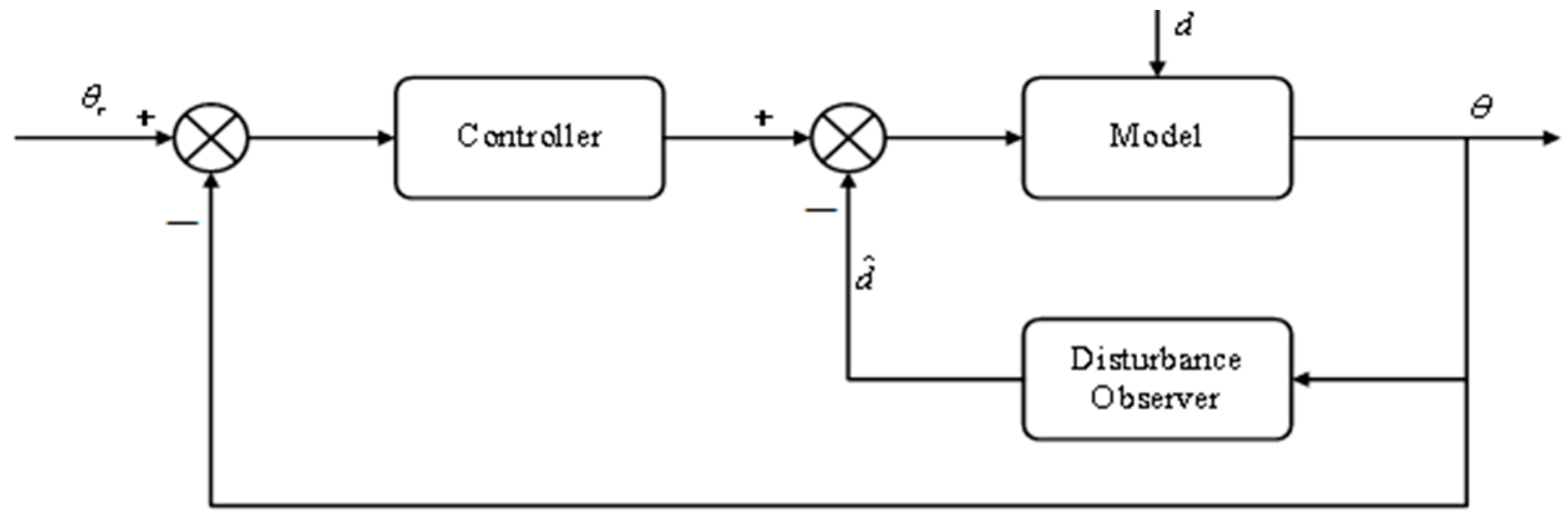
  • A Disturbance-Observer-Based Deep Deterministic Policy Gradient is proposed, which is aimed at effectively suppressing frictional disturbances and enhancing the control performance and robustness of the system.

2. Model

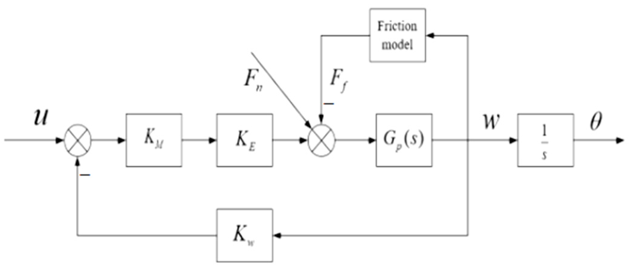
2.1. Stabilized Platform Model

In accordance with the operational principles of a stabilized platform within rotary steerable drilling [16,17,18,19], we have formulated a comprehensive controlled object model for the stabilized platform, which is illustrated in Figure 1.
In the figure, K M is the PWM to MOS tube ratio, K E is the turbine electromagnetic torque to current ratio, K w is gyroscope conversion coefficient, F n is the external disturbance torque, and F f is friction torque.
Assuming x 1 = θ and x 2 = ω , the mathematical model of the stabilized platform control system can be expressed as:
{ x ˙ 1 = x 2 x ˙ 2 = K M K E K W K m + 1 T m x 2 + K M K E K m + 1 T m u K m T m F ,
where F = F f + F n , K m = C m f R a + C m C e is the transmission coefficient, T m = J R a f R a + C m C e is the electromechanical constant, and J , R a , f , C m , and C e represent the rotational inertia, armature resistance, viscous friction coefficient, motor torque coefficient, and counterelectromotive force coefficient, respectively.

2.2. Friction Characteristic Model

Given the complexity of the underground drilling environment, the control system of the stabilized platform is susceptible to the influence of nonlinear friction. Consequently, it is necessary to conduct a thorough analysis and research of the friction model. The LuGre model, initially proposed by Canudas in 1995, provides a comprehensive framework for describing the dynamic and static aspects of various friction phenomena [20,21].
The expression for the LuGre model is as follows:
F f = σ 0 z + σ 1 d z d t + σ 2 w ,
d z d t = w | w | g ( w ) z ,
g ( w ) = F c + ( F s F c ) e ( w w s ) 2 ,
where ω s is the angular velocity of the tool face; Z is the deformation of the bristle; F f , F c , and F s represent the friction torque, Coulomb friction, and static friction, respectively; and σ 0 , σ 1 , and σ 2 represent the stiffness coefficient, viscous damping coefficient, and viscous friction coefficient, respectively.
The LuGre friction model effectively describes both static and dynamic frictional processes. Moreover, it possesses the capacity to elucidate intricate phenomena, encompassing viscous friction, Coulomb friction, and Stribeck friction. In the context of operating the control system for a stabilized platform employed in rotary steerable drilling, it is essential to acknowledge the potential manifestation of non-linear frictional effects. These effects encompass phenomena such as low-speed crawling, steady-state error, and limit cycle oscillation. Given the inherent compatibility between the friction characteristics modeled via the LuGre model and the friction encountered during the rotational processes of the stabilized platform, we select the LuGre model for integration into the control system and conduct rigorous research and analysis.

3. Design of Deep Reinforcement Learning Controller Based on DDPG_DOB

3.1. DDPG Algorithm

The policy-based approach has effectively addressed the limitation of value-based deep reinforcement learning algorithms, which often face challenges when dealing with continuous action spaces. However, when confronted with potentially infinite action spaces, this method may inadvertently lead to convergence on local optima rather than achieving globally optimal solutions. To address this challenge, Sutton introduced a novel reinforcement learning framework known as Actor–Critic, building upon the principles of the DDPG algorithm [22,23].
The DDPG algorithm implements the Actor–Critic framework, where the Actor is responsible for policy updates, and the Critic manages adjustments to the action value function [24,25]. Deep neural networks serve as nonlinear function approximators for both the Actor networks μ ( s | θ μ ) and Critic networks Q ( s , a | θ Q ) . The Critic network is updated by minimizing the mean square error, guiding the Actor network’s policy updates to select appropriate actions. After extensive training, the optimal value target is achieved.
To mitigate the correlation between the current Q-value and the target Q-value, a dual network architecture is utilized for both the policy and value functions. In this architecture, both the policy network and the value network consist of online and target networks. The online network is tasked with updating the current network parameters, while the target network is dedicated to optimizing the target value.

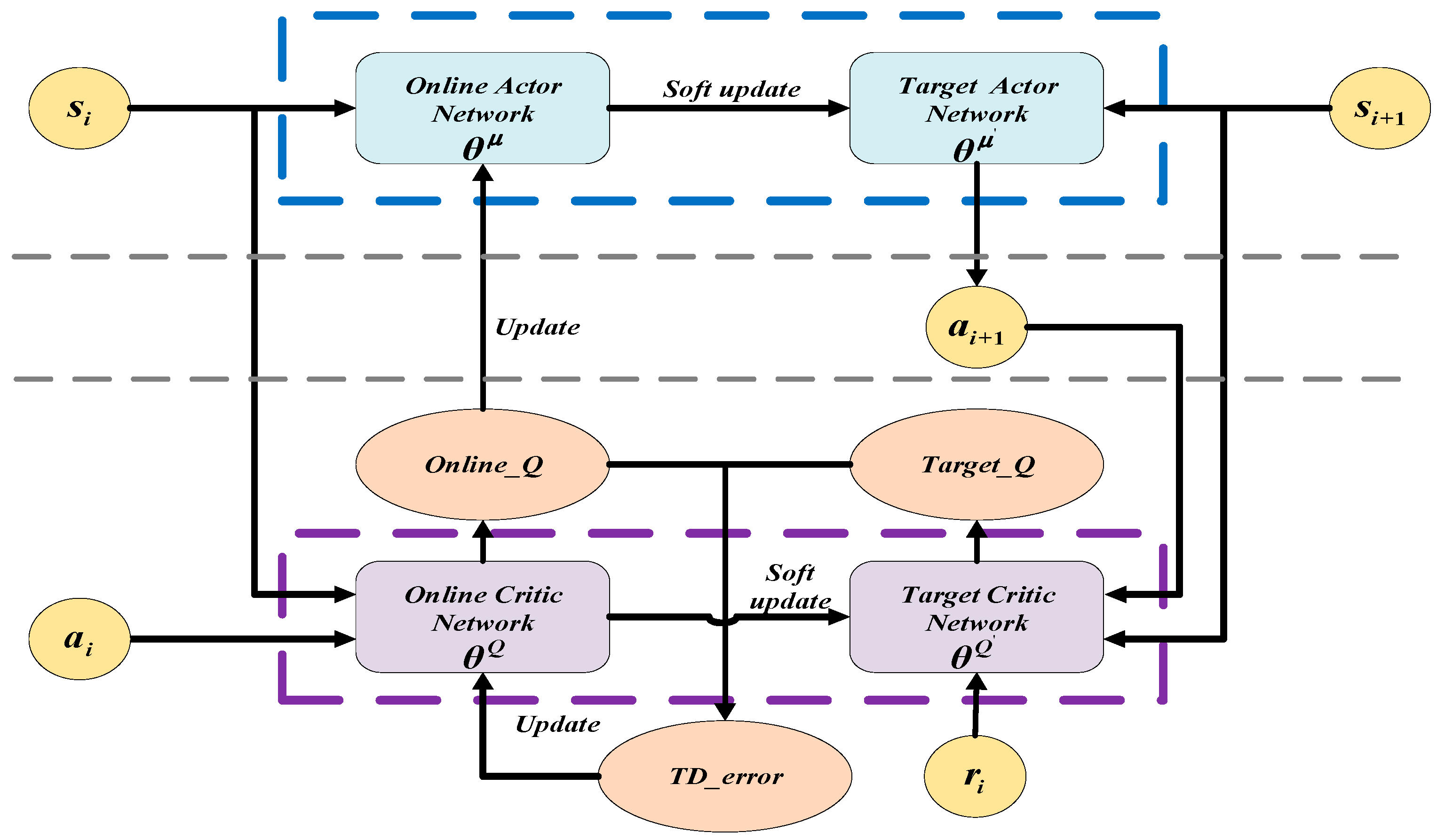
3.2. Parameters Updating of DDPG Algorithm

The process of updating parameters in the DDPG algorithm is depicted in Figure 2.
While updating network parameters, a small batch of samples is randomly selected from the experience pool to train the network. The target value is calculated using the target Critic network, as expressed in Equation (5):
y i = r i + γ Q ( s i + 1 , μ ( s i + 1 | θ μ ) | θ Q ) ,
In Equation (5), y i represents the Q-value of the current action, r i is the reward for each step, γ is the discount factor, μ ( . ) is the target policy, Q ( . ) refers to the target value, and θ μ , θ Q denote the network parameters of the target Actor and target Critic networks, respectively.
The current value of Q is calculated based on the current state value s i and action value a i . Subsequently, the online Critic network is updated by minimizing the loss function, as shown in Equation (6):
L ( θ Q ) = 1 N i ( y i Q ( s i , a i | θ Q ) T D _ e r r o r ) 2 ,
In Equation (6), θ Q represents the parameter of the online Critic network, and N signifies the number of samples.
Parameter updates to the online Actor network are executed through policy gradient techniques, optimizing reward maximization.
The objective function of the DDPG algorithm is defined as the expected value of the discounted cumulative reward θ Q :
J ( θ μ ) = E μ ( r 1 + γ r 2 + γ 2 r 3 + + γ n r n + 1 ) ,
To enhance the agent’s reward acquisition, the parameter θ μ should be updated to maximize this objective function. Q ( s i , a i | θ Q ) , with the aim of maximizing the objective function. Consequently, the chain rule method is employed to derive the gradient of the objective function.
θ μ 1 N i ( a Q ( s , a | θ Q ) | s = s i , a = μ ( s i ) θ μ μ ( s | θ μ ) | s = s i ) ,
where μ ( s | θ μ ) | s = s i denotes the deterministic policy; Q ( s , a | θ Q ) | s = s i , a = μ ( s i ) signifies the generation of values Q by selecting actions based on the deterministic policy μ in a given state s i . The gradient ascent algorithm is employed to modify the parameters θ μ of the objective function.
Furthermore, the target network parameters undergo modification through the application of a soft update technique, incrementally adjusting the target network at each time step, as detailed in Equation (9):
{ θ Q τ θ Q + ( 1 τ ) θ Q θ μ τ θ μ + ( 1 τ ) θ μ ,
where τ symbolizes the soft update coefficient, θ μ represents the parameters of the online Actor network, θ Q represents the parameters of the online Critic network, θ μ denotes the attributes of the target Actor network, and θ Q signifies the characteristics of the target Critic network.
Throughout the training process, the utilization of the soft update method serves to maintain gradual changes in the target network parameters, facilitating a consistent gradient computation for the online network and fostering facile convergence during the training procedure.

4. Design of Deep Reinforcement Learning Controller for Stabilized Platform

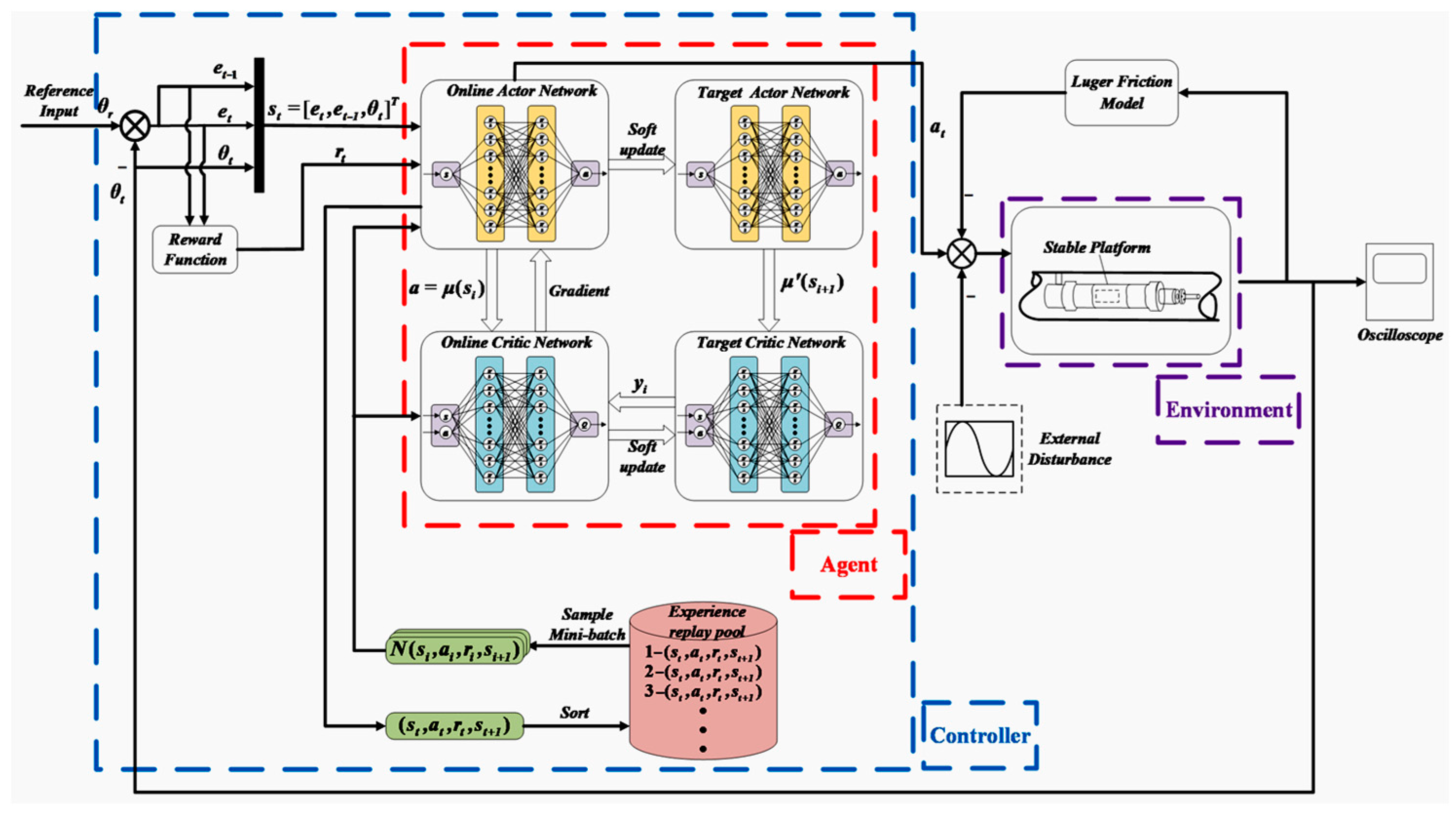
4.1. Overview of the Control System Framework

This framework primarily comprises three key components: the DDPG controller, the controlled object model of the stabilized platform, and the friction disturbance model (Figure 3).
In this figure, the DDPG controller receives a state vector, denoted as s t , and generates a corresponding action a t through the policy network. The reward value, represented as r t , is obtained by executing the action on the stabilized platform using utilizing the value network. Simultaneously, the current training sample is stored within the experience replay pool, with each data point stored in the form of a quaternion array ( s t , a t , r t , s t + 1 ) . A small batch of samples is randomly selected from the experience replay pool, and the controller undergoes extensive training to update the weight parameters of the Actor and Critic networks, achieving a non-linear approximation of both networks and improving the control effect of the deep reinforcement learning algorithm.
Subsequently, with the DDPG algorithm and the stabilized platform model as the foundation, we proceed to select the appropriate state vector and design the reward function.

4.2. Selecting State Vectors

In the context of stabilized platform control, the reference tool face serves as the system input, denoted as θ t . The difference between the reference tool face angle and the current tool face angle is e t = θ r θ t , while the difference between the reference tool face angle and the tool face angle from the previous moment is e t 1 = θ r 1 θ t 1 .
To achieve the desired tracking performance in the stabilized platform control problem, it is essential to adjust the current tool face angle in accordance with the reference tool face angle. As a result, when selecting state variables, the current tool face angle θ t and the current error e t become pivotal considerations. Moreover, to ensure that the current state progresses in the direction of a minimized error, we include the previous moment’s error e t 1 as a state value. In summary, the state vector at the current moment is constructed as follows:
s t = [ e t , e t 1 , θ t ] T .

4.3. Designing the Reward Function

When formulating the reward function, we take into account the impact of system error on system control performance. When the current error, denoted as θ t , approaches θ r , signifying a smaller error, a higher desired reward value is sought. Consequently, the reward function is structured as the summation of the current error value e t and previous moment’s error e t 1 . The design of the reward function ensures a positive reward when both the current error and the previous moment’s error fall within the expected range. Any deviation beyond this range results in a negative penalty.
The reward function at the current moment can be expressed as:
r t = α r 1 ( t ) + β r 2 ( t ) ,
r 1 ( t ) = { 1 , | e ( t ) ε 1 | 1 α , e l s e ,
r 2 ( t ) = { 1 , | e ( t 1 ) ε 2 | 1 β , e l s e .
In the equation, r 1 ( t ) and r 2 ( t ) represent the current error reward value and the previous moment error reward value, respectively. Additionally, α and β symbolize the current error reward value coefficient and the previous moment error reward value coefficient, respectively. These coefficients are instrumental in fine-tuning the relative importance of r 1 ( t ) and r 2 ( t ) in the reward value calculation. Furthermore, ε 1 and ε 2 denote the permissible error ranges for the current moment error and the previous moment error, respectively.

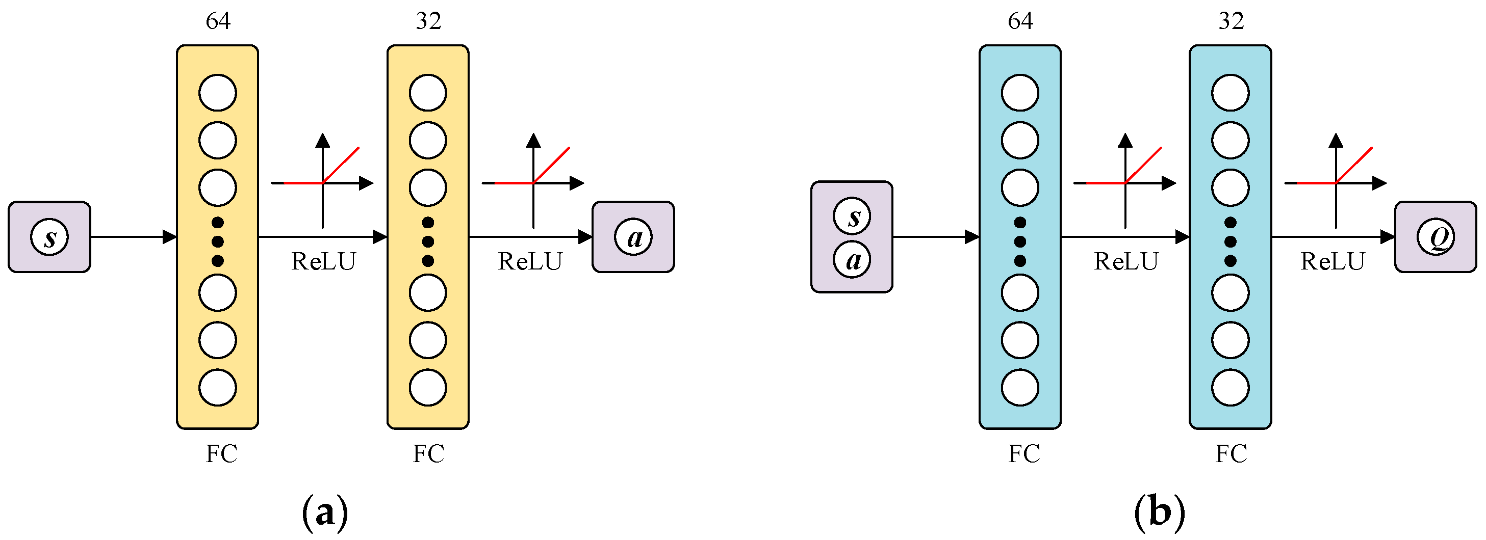
4.4. Network Structure Design

In line with the preceding discussion and following the principles of the DDPG algorithm, the designed DDPG controller adopts a dual network framework encompassing the Actor and the Critic, each consisting of both online and target networks. These network structures exhibit complete structural congruence aside from their parameterization. Figure 4 provides a graphical representation of the Actor and Critic network architectures. The Actor network’s input layer interfaces with the state vector, denoted as s t . It includes two fully connected neural layers, consisting of 64 and 32 nodes, with Rectified Linear Unit (ReLU) activation functions. The output layer produces the action a t , representing the control variable chosen by the agent within the current-state context. Conversely, the Critic network’s input layer accommodates both the state vector, s t , and the action, a t . The output layer generates the value associated with the agent’s action selection under the present-state conditions. The overall structural composition of the Critic network mirrors that of the Actor network, maintaining consistency throughout.
In accordance with the state vector, reward function, and network structure design of the DDPG controller as elucidated earlier, the iterative process of tracking the tool face angle unfolds. During each iteration, the network parameters undergo calculated adjustments until the system achieves convergence with the desired ideal state.

4.5. Design of DDPG_DOB

In the practical environment, the stabilized platform control system is affected by frictional disturbance, which results in nonlinear characteristics, such as dead-zone nonlinearity and saturation, which lead to steady-state error, oscillation, and hysteresis phenomena within the system. Therefore, this section proposes the integration of a disturbance observer to accurately estimate and compensate for frictional disturbances, thereby eliminating their adverse effects on a stabilized platform.
The structural configuration of the stabilized platform control system enhanced by the incorporation of a disturbance observer is shown in Figure 5.
The utilization of a disturbance observer plays a crucial role in estimating and mitigating disturbances. This approach enables the real-time adjustment of the controller’s output based on the observed disturbances, subsequently altering the input to the stabilized platform-controlled object. As illustrated in Figure 5, the disturbance observer takes the tool face angle as input and generates an estimated value for external disturbances. Simultaneously, the DDPG controller undergoes training, taking into account the current tool face angle and the tool face angle error. The disparity between the controller’s output and the disturbance observer’s output serves as the input to the stabilized platform-controlled object. The operational principle of the disturbance observer is elucidated in Figure 6.
As depicted in Figure 6, the diagram elucidates the following components: u is the input to the controller; G ( s ) symbolizes the transfer function of the controlled object; y signifies the system’s control output; G n 1 ( s ) denotes the inverse of the nominal model; Q ( s ) is the low-pass filter; d signifies the disturbance; d ^ represents the estimated value of the disturbance d ; ξ accounts for measurement noise; and u is the control input to the system.
These components collectively contribute to the control inputs of the system:
u = u d ^ + d ,
As delineated in Figure 6, when the controller output signal is denoted as U ( s ) , the disturbance signal as D ( s ) , and the measurement noise as N ( s ) , their corresponding transfer functions are represented as follows:
G U Y = Y ( s ) U ( s ) = G ( s ) G n ( s ) G n ( s ) + Q ( s ) ( G ( s ) G n ( s ) ) ,
G D Y = Y ( s ) D ( s ) = G ( s ) G n ( s ) ( 1 Q ( s ) ) G n ( s ) + Q ( s ) ( G ( s ) G n ( s ) ) ,
G N Y = Y ( s ) N ( s ) = G ( s ) Q ( s ) G n ( s ) + Q ( s ) ( G ( s ) G n ( s ) ) ,
Leveraging Equation (14), Figure 6 is streamlined to Figure 7 through equivalent transformation.
The mathematical expression of the low-pass filter is:
Q ( s ) = 1 + k = 1 N 2 a k ( τ s ) k 1 + k = 1 N a k ( τ s ) k ,
where N signifies the order of the denominator; a k = N ! k ! ( N k ) ! represents the coefficient; and τ denotes the time constant.
The incorporation of a disturbance observer into the system enables the observation of equivalent disturbances that affect the system, enabling disturbance compensation within the control framework. Ultimately, this leads to effective disturbance suppression, mitigating the impact of disturbances on the control system.

5. Simulation

In this section, we seek to verify the superiority and control accuracy of the DDPG_DOB algorithm presented in the previous section through a comprehensive assessment encompassing key aspects: tracking simulation experiments, step simulation experiments, and robustness experiments. The parameters listed in Table 1 and Table 2 correspond to the actual parameters of the drilling tool and are derived from measurements or known values in the field. These parameters are crucial for accurately modeling the drilling system and ensuring the validity of our simulations.

5.1. Parameter Description

The stabilized platform model [26], LuGre friction model, and neural network training parameters are shown in Table 1, Table 2 and Table 3, respectively.

5.2. Simulation Results and Analysis

In the presence of friction disturbances, we conducted a series of simulation and analysis experiments, encompassing both tool face angle set-point control and tool face angle tracking control. The study involved a comparative analysis of the DDPG_DOB control algorithm against the conventional PID, PID_DOB, and DDPG algorithms.

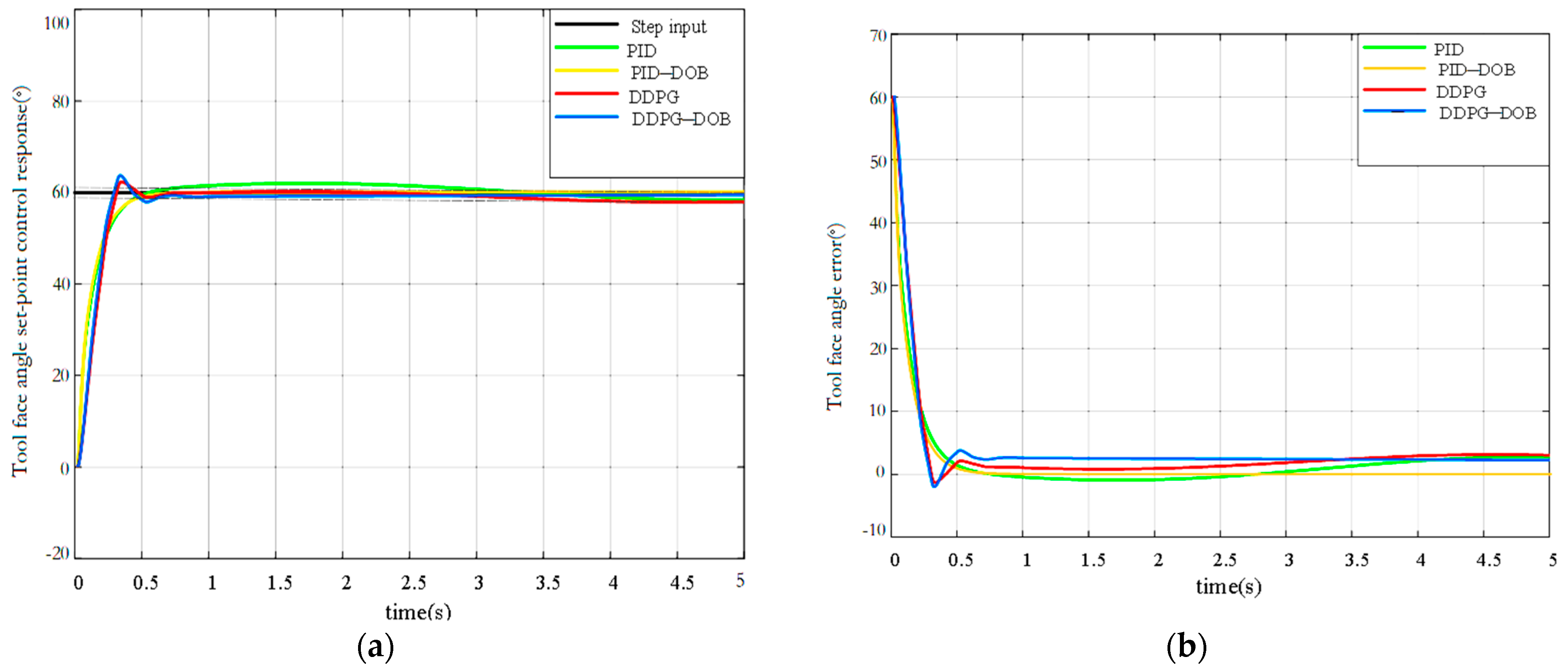
5.2.1. Tool Face Angle Step Simulation with Friction

For the simulation, we employed a tool face angle set to 60 degrees using a step signal, the external disturbance signal was set as F n = sin   ( t + π ) , and the friction disturbance was modeled as the LuGre friction. The experimental results of the PID, PID_DOB, DDPG, and DDPG_DOB control methods are presented in Figure 8 and Table 2.
Based on the results shown in Figure 8 and Table 4, in comparison to PID, PID_DOB, and DDPG, the DDPG_DOB controller exhibited a substantial reduction in steady-state error by 0.023 ° , 0.012 ° , and 0.014 ° . While it displayed a slightly higher overshoot, the DDPG_DOB algorithm demonstrated the shortest settling time and rise time. These findings underscore the effectiveness of the refined DDPG_DOB control approach, highlighting its ability to enhance the system’s response speed and mitigate steady-state error, thereby significantly improving the overall control performance.

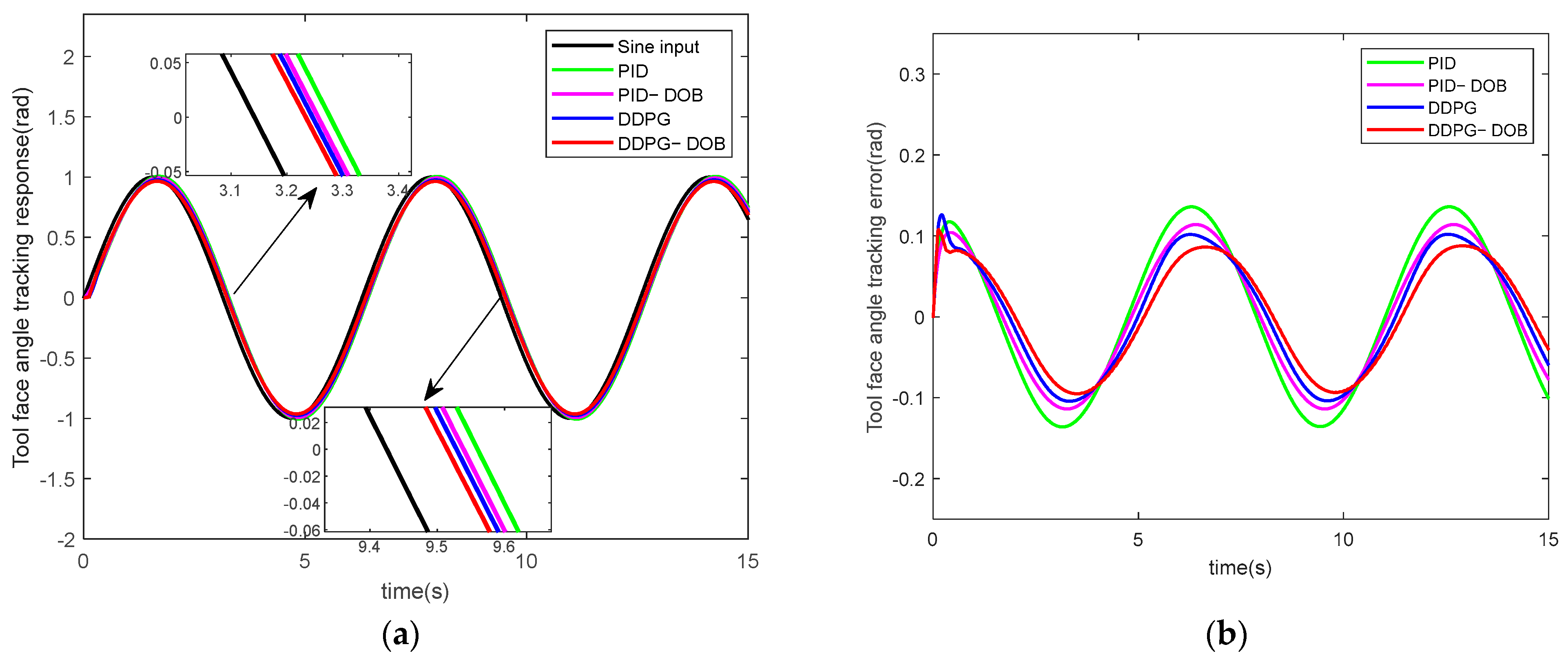
5.2.2. Tool Face Angle Simulation with Friction

The input signal of the system was set as θ r = sin   ( π t ) , the external disturbance signal was set as F n = sin   ( t + π ) , and the friction disturbance was modeled as the LuGre friction. Figure 9 shows the comparative experimental results of PID, PID_DOB, DDPG, and DDPG_DOB control methods.
From Figure 9, it is evident that the DDPG_DOB method outperforms both the PID algorithm and the DDPG algorithm in terms of tracking accuracy and tracking error, maintaining the tracking error within 8.7%. The stabilizing platform significantly enhances control performance, and the DDPG_DOB control method is effective at suppressing disturbances.

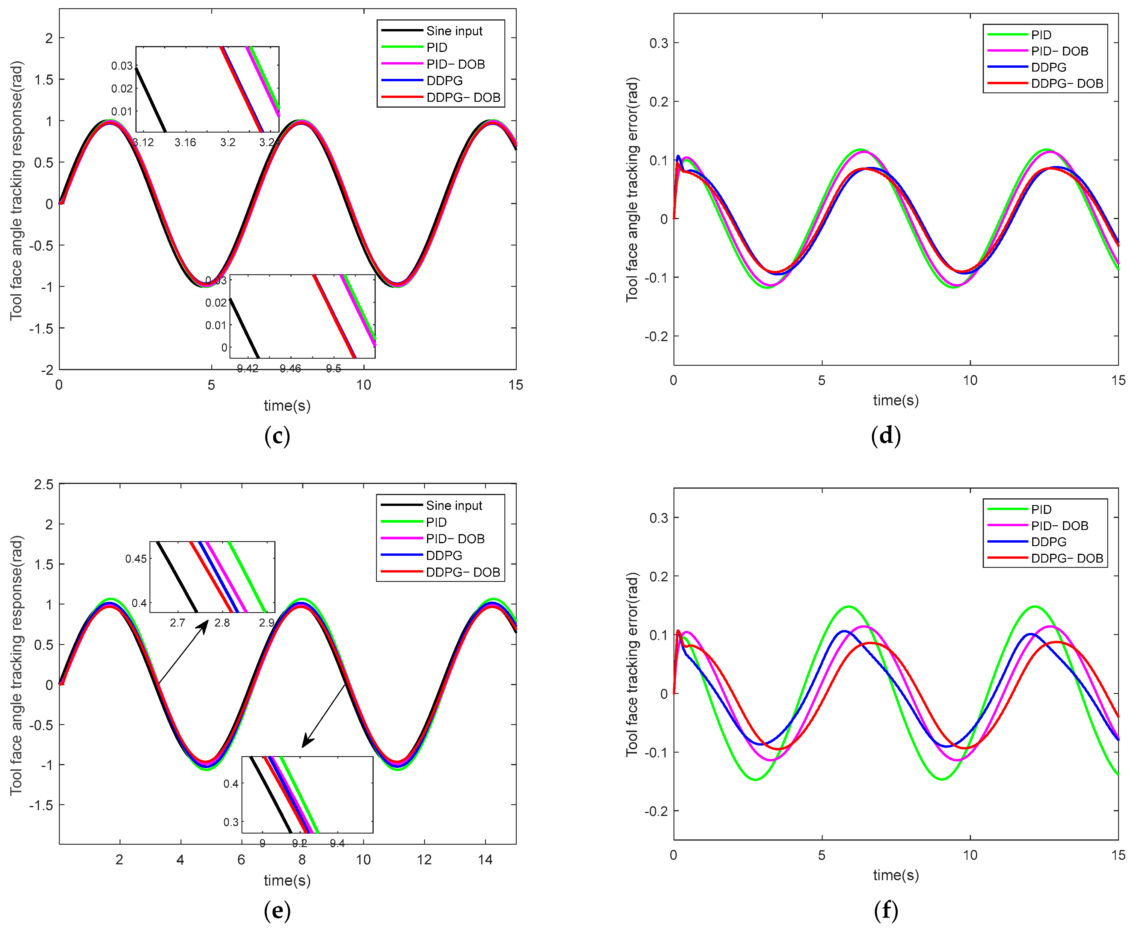
5.2.3. Robustness Experimental Research

Experiments were conducted to evaluate the robustness of the stabilized platform control system under variations in rotational inertia J armature resistance R a , and external disturbance F n . The simulation results are presented in Figure 10, and Table 3 shows the maximum error of the control system for the stabilized platform, as shown in Figure 10.
The results presented in Figure 10 and Table 5 provide a clear conclusion. Even in the presence of parameter variations, both the PID and DDPG control methods demonstrate the capability to achieve a certain level of tracking precision. However, it is noteworthy that PID control exhibits a significant increase in error, leading to a deviation from the desired accuracy in tool face angle tracking. In contrast, DDPG control, while displaying lower error rates compared to PID, faces challenges related to latency. Remarkably, the DDPG_DOB algorithm displays superior control effectiveness, highlighting its ability to mitigate parameter variations, reduce the impact of frictional disturbances, and demonstrate robust and resilient performance. Consequently, the DDPG_DOB method proposed in this study emerges as a more suitable choice for the control system of a rotary directional drilling stabilizing platform.

6. Conclusions

In this study, we investigate the stabilized platform of a rotary steering drilling system and establish a mathematical model. To address issues related to friction and unknown disturbances, a DDPG_DOB-based attitude control algorithm is proposed. Specifically, to mitigate the impact of nonlinear friction interference on the stabilized platform, a disturbance observer is introduced for estimation. The numerical simulation experiments on the stabilized platform attitude control system validate the effectiveness of the DDPG_DOB method, with results as follows:
DDPG_DOB achieves a tracking response error range of 8.7%, outperforming PID and DDPG in terms of control accuracy, nonlinearity, and anti-disturbance capability.
The DDPG_DOB method showcases distinct advantages over PID, PID_DOB, and DDPG; reduces steady-state errors by 0.023°, 0.012°, and 0.014°; and the settling time and rise time are the shortest. These improvements underscore its efficacy in enhancing response speed and accuracy.
The DDPG_DOB-stabilized platform control system shows the effective suppression of the effects of rotational inertia, armature resistance ingestion, and external disturbance amplitude varieties on the system. This system exhibits good adaptive ability and strong robustness under complex and continuous working conditions.

Author Contributions

Conceptualization, A.H.; Methodology, S.Z.; Software, A.H., X.J. and S.Z.; Validation, X.J.; Writing—original draft, X.J.; Writing—review & editing, A.H.; Funding acquisition, A.H. All authors have read and agreed to the published version of the manuscript.

Funding

This research was partially supported by the General Project of Shaanxi Provincial Science and Technology Department-Industrial Field (grant numbers: 2020GY-152 and 2022GY-135), the Scientific Research Project of the Key Laboratory of Education Department of Shaanxi Province (grant number: 17JS108), and the Postgraduate Innovation and Practice Ability Development Fund of Xi’an Shiyou University (grant number: YCS22112057).

Institutional Review Board Statement

Not applicable.

Informed Consent Statement

Not applicable.

Data Availability Statement

The data presented in this study are available in this article.

Conflicts of Interest

The authors declare no conflict of interest.

References

  1. Zhang, S.-H. New progress and development direction of modern steering drilling techniques. Acta Pet. Sin. 2003, 24, 82–85, 89. [Google Scholar]
  2. Su, Y.-N.; Dou, X.-R.; Wang, J.-J. Function, characteristics and typical structure of rotary steering drilling system. Oil Drill. Prod. Technol. 2003, 25, 5–7. [Google Scholar]
  3. Li, T. Discussion on research status and development trend of rotary steering drilling technology. Petrochem. Ind. Technol. 2016, 18, 165–171. [Google Scholar]
  4. Xiao, S.-H.; Liang, Z. Development status and prospect of rotary steering drilling technology. China Pet. Mach. 2006, 34, 66–70. [Google Scholar]
  5. Wang, W.; Geng, Y.; Wang, N. Toolface Control Method for a Dynamic Point-the-Bit Rotary Steerable Drilling System. Energies 2019, 12, 1831. [Google Scholar] [CrossRef]
  6. Cui, Q.-L.; Zhang, S.-H.; Liu, Y.-X. Study on Controlling System for Variable Structure of Stabilized Platform in Rotary Steering Drilling System. Acta Pet. Sin. 2007, 28, 120–123. [Google Scholar]
  7. Yan, W.-H.; Peng, Y.; Zhang, S.-H. Mechanism of Rotary Steering Drilling tool. Acta Pet. Sin. 2005, 26, 98–101. [Google Scholar]
  8. Song, H.-X.; Zeng, Y.-J.; Zhang, W. Current Situation and Key Technology Analysis of Rotary Steering System. Sci. Technol. Eng. 2021, 21, 2123–2131. [Google Scholar]
  9. Li, Y.-D.; Cheng, W.-B.; Tang, N. The Intelligent PID Control of the Rotary Navigational Drilling Tool. China Pet. Mach. 2010, 38, 13–16. [Google Scholar]
  10. Huo, A.-Q.; He, Y.-Y.; Wang, Y.-L. Study of Fuzzy Adaptive Sliding Mode Control for Rotary Steering Drilling Stable Platform. Compute. Simul. 2010, 27, 152–155. [Google Scholar]
  11. Wang, Y.-L.; Wang, H.-J.; Kang, S.-M. Output Feedback Linearization of Servo Platform for Rotary Steering Drilling System. Acta Pet. Sin. 2014, 35, 952–957. [Google Scholar]
  12. Modares, H.; Lewis, F.-L.; Kang, W. Optimal synchronization of heterogeneous nonlinear systems with unknown dynamics. IEEE Trans. Autom. Control 2018, 63, 117–131. [Google Scholar] [CrossRef]
  13. Liu, H.; Zhao, W.; Lewis, F.-L. Attitude synchronization for multiple quadrotors using reinforcement learning. In Proceedings of the Chinese Control Conference, Guangzhou, China, 27–30 July 2019; pp. 2480–2483. [Google Scholar]
  14. Wang, Y. Nonlinear Control Method for Rotary Steering Drilling Servo Platform. Ph.D. Thesis, Northwestern Polytechnical University, Xi’an, China, 2012. [Google Scholar]
  15. Zhang, Z.; Li, X.; An, J. Model-free optimal attitude control of spacecraft with external disturbance and input saturation based on DRL. In Proceedings of the IEEE 10th Joint International Information Technology and Artificial Intelligent Conference, Chongqing, China, 17–19 June 2022; pp. 100–112. [Google Scholar]
  16. Tang, N.; Huo, A.-Q.; Wang, Y.-L. Experimental Study on Control Function of Stabilized Platform for Rotary Steerable Drilling Tool. Acta Pet. Sin. 2008, 29, 284–287. [Google Scholar]
  17. Wang, Y.-L.; Fei, W.-H.; Huo, A.-Q. Electromagnetic Torque Feed Forward Control of the Turbine Alternator for Rotary Steerable Drilling Tools. Acta Pet. Sin. 2014, 35, 141–145. [Google Scholar]
  18. Tang, N.; Mu, X.-Y. Study on the Platform Stabilizing Control Mechanism of Modulating Rotary Steerable Drilling Tool. Oil Drill. Prod. Technol. 2003, 25, 9–12, 81. [Google Scholar]
  19. Huo, A.-Q.; Qiu, L.; Wang, Y.-L. Sliding Mode Variable Structure Control of Stabilized Platform in Rotary Steering Drilling System Based on RBF Neural Network. J. Xi’an Shiyou Univ. 2016, 31, 103–108. [Google Scholar]
  20. Canudas de Wit, C.; Olsson, H.; Astrom, K.J. A New Model for Control of Systems with Friction. IEEE Trans. Autom. Control 1995, 40, 419–425. [Google Scholar] [CrossRef]
  21. Mashayekhi, A.; Behbahani, S.; Nahvi, A.; Keshmiri, M.; Shakeri, M. Analytical describing function of LuGre friction model. Int. J. Intell. Robot. Appl. 2022, 6, 437–448. [Google Scholar] [CrossRef]
  22. Park, K.-W.; Kim, M.; Kim, J.-S.; Park, J.-H. Path Planning for Multi-Arm Manipulators Using Soft Actor-Critic Algorithm with Position Prediction of Moving Obstacles via LSTM. Appl. Sci. 2022, 12, 9837. [Google Scholar] [CrossRef]
  23. Zhao, J.; Zhu, T.; Gao, Z.-Q. Actor-Critic for Multi-Agent Reinforcement Learning with Self-Attention. Int. J. Pattern Recognit. Artif. Intell. 2022, 36, 2252014. [Google Scholar] [CrossRef]
  24. Syavasya, C.V.S.R.; Muddana, A.L. Optimization of autonomous vehicle speed control mechanisms using hybrid DDPG-SHAP-DRL-stochastic algorithm. Adv. Eng. Softw. 2022, 173, 103245. [Google Scholar]
  25. Wu, L.; Wang, C.; Zhang, P. Deep Reinforcement Learning with Corrective Feedback for Autonomous UAV Landing on a Mobile Platform. Drones 2022, 6, 238. [Google Scholar] [CrossRef]
  26. Huo, A.-Q. Mode Identification and Control Method of Stabilized Platform in Rotary Steerable Drilling. Ph.D. Thesis, Northwestern Polytechnical University, Xi’an, China, 2012. [Google Scholar]
Figure 1. Control object model of stabilized platform.
Applsci 13 12022 g001
Figure 2. Parameter update process of the DDPG algorithm.
Applsci 13 12022 g002
Figure 3. Stabilized platform attitude control system.
Applsci 13 12022 g003
Figure 4. (a) Actor network structure and (b) Critic network structure.
Applsci 13 12022 g004
Figure 5. Structure diagram of the stabilized platform control system enhanced with a disturbance observer.
Applsci 13 12022 g005
Figure 6. Principle block diagram of disturbance observer.
Applsci 13 12022 g006
Figure 7. Simplified block diagram of disturbance observer through equivalent transformation.
Applsci 13 12022 g007
Figure 8. (a) Tool face step response of control system with frictional disturbances and (b) tool face step error of control system with frictional disturbances.
Applsci 13 12022 g008
Figure 9. (a) Tool face tracking response of control system with frictional disturbances and (b) tool face tracking error of control system with frictional disturbances.
Applsci 13 12022 g009
Figure 10. (a) Tool face tracking response and (b) tracking error when J and R a are increased by 50%; (c) tool face tracking response and (d) tracking when J and R a are decreased by 50%; (e) tool face tracking response and (f) tracking error with 4 times the amplitude of F n .
Applsci 13 12022 g010aApplsci 13 12022 g010b
Table 1. Stabilized platform parameters.
Parameter NameNumerical Value
PWM to MOS tube ratio K M / ( A / V ) 3.440
Gyroscope conversion coefficient K W / ( V / r a d / s ) 5.74
Turbine electromagnetic torque to current ratio K E / ( N . m / A ) 0.22
Rotational inertia J / ( k g . m 2 ) 0.03
Armature resistance R a / ( Ω ) 12.50
Viscous friction coefficient f 0.270
Motor torque coefficient C m 3.820
Counterelectromotive force coefficient C e 0.44
Table 2. The LuGre model parameters.
Parameter NameNumerical Value
Friction torque F f / ( N ) 0.5991
Coulomb friction F c / ( N ) 2.440
Tool face angular velocity ω s / ( m / s ) 0.0103
Stiffness coefficient σ 0 0.4766
Viscous damping coefficient σ 1 0.2701
Viscous friction coefficient σ 2 0.0049
Table 3. Hyperparameter values.
Parameter NameNumerical Value
Discount factor0.995
Actor learning rate 10 4
Critic learning rate 10 3
Maximum return combined number5000
Per round number of steps200
Soft update parameters 10 3
Experience pool capacity 10 6
Number of samples per training64
Table 4. Comparison of system performance indicators.
Control MethodPIDPID_DOBDDPGDDPG_DOB
Overshoot (%)004.7627.143
Settling time ( ± 5 % , s)3.1812.4540.7270.636
Steady-state error ( )−0.0470.036−0.0380.024
Rise time (s)0.5450.5090.2950.236
Table 5. Control system maximum error.
J R a F n PIDPID_DOBDDPGDDPG_DOB
---------0.1260.1130.0930.085
1.5 J1.5 Ra---0.1350.1130.1010.086
1.5 J0.5 Ra---0.1170.1140.0880.084
------4 Fn0.1470.1140.1010.086
Disclaimer/Publisher’s Note: The statements, opinions and data contained in all publications are solely those of the individual author(s) and contributor(s) and not of MDPI and/or the editor(s). MDPI and/or the editor(s) disclaim responsibility for any injury to people or property resulting from any ideas, methods, instructions or products referred to in the content.

