Abstract
Numerous studies about solar panel cleaning robot (SPCR) have been conducted globally to enhance the performance of photovoltaic panels (PV panels). However, there is a reality: scant attention has been paid to the large pressure and vibration that SPCR movements induce, not only on the photovoltaic panel surface but also on the mounting structure. Most of the research is focused on evaluating the “cleanliness” of the PV surface by using a clearing robot or the effects of natural factors (wind, dust, etc.) on the PV panels. Nonetheless, the large pressure and vibration constitute one of the primary factors contributing to the degradation of photovoltaic panel longevity and efficiency, especially affecting poorly installed PV arrays. To address these issues, this study proposes the design of a multi-suspension unit for the SPCRs equipped with track-wheeled, which might reduce vibration on the PV panel surface generated by the SPCRs’ motion and brushing action during operation. The multi-suspension unit facilitates the expansion of the contact area between the track-wheeled and the PV panel surface; hence, the negative effect is reduced owing to the vibration-absorbing properties of the rubber track pads. In the case of a static SPCR state, with only the impact of rotating brushes on vibration, the effectiveness of the multi-suspension unit can reduce vibration by a maximum of 72.63. Moreover, a metric (Δz) is proposed to evaluate the change in deflection of PV panels over time. The results show that the number of significant changes in PV panel deflection gradually decreases or disappears, while the number of small changes increases. In the case of SPCR operating on portrait PV modules, the number of occurrences of Δz (greater than 0.5 mm) is reduced from 18 counts to 5 counts, while the number of occurrences of Δz (less than 0.5 mm) increased from 61 counts to 91 counts. Overall, the proposed multi-system suspension is effective in reducing or eliminating large deflections while keeping the vibration frequency constant.
1. Introduction
In recent years, the solar energy industry has witnessed significant growth, with the total installed capacity worldwide increasing by nearly 650 GW over the past decade [1]. Solar power has become a leading renewable energy source due to its renewability, cost-effectiveness, smaller installation space requirements, and lower maintenance costs compared to other energy sources [2]. However, maintaining the performance of photovoltaic panel (PV panel) systems is crucial as factors like dust and debris can reduce their efficiency by up to 30% [3]. Regular cleaning of photovoltaic (PV) systems is, therefore, essential.
Currently, various PV panel cleaning methods are employed worldwide, such as using polymer bristle brushes, automatic water spraying systems, solar panel cleaning robots (SPCRs) with cleaning tools, electrostatic force, nano coatings or special chemicals, ultrasonic waves, and combinations of brushes with specialized cleaning solutions [4,5]. Each method has its advantages and disadvantages depending on the PV panel installation structure and the specific dust characteristics of the region. Among these methods, using a mobile robot equipped with two track-wheeled systems is considered a promising solution for the future due to its high flexibility, rapid cleaning speed, and high work efficiency [6]. However, the dynamic loads generated by the SPCR during its movement on the panel surface can lead to problems that directly impact the lifespan and performance of the PV panels. Dynamic or static forces applied to the panels may induce microcracks inside the silicon cells [7] and cause deformation [8]. Consequently, panels degrade at a rate of 0.8–1.1% per year, resulting in a 20% decrease in photovoltaic efficiency over twenty years [9]. Moreover, the dynamic forces produced by the SPCR during operation not only affect the lifetime of PV panels but also impact mounting frames. For structurally unstable trusses, the joints are vulnerable to failure when subjected to continuous dynamic forces, which not only affects operating costs but also poses risks to cleaning and maintenance workers. Nevertheless, the impact of SPCR on PV panels has received limited research attention. An overview of previous investigations is presented in Table 1 for comparison.

Table 1.
Summary of previous studies.
To address the aforementioned problems, this study proposes the design of a multi-suspension unit supporting track-wheeled systems that are equipped with SPCRs to minimize the vibration caused by the motion of the SPCR on PV panels. The structure of the multi-suspension unit is inspired by a tank track suspension [14] with adjustable spring travel. It is important to note that the multi-suspension unit serves as a supplementary component to the existing track-wheeled system, rather than requiring a complete redesign. Relevant calculations are performed to determine the parameters of the single suspension unit, including the length of the links, the position of the joints, and the spring component’s parameters, which are then replicated for the others. The curved profile of the deformed PV panel, serving as the initial condition for the design, is determined through simulation using the Finite Element Method (FEM) in ANSYS. To ensure flexibility with different SPCRs and PV arrays, the design process is represented by equations with variable parameters that depend on conditions such as the type of PV panels, the mounting space of the track-wheeled system, the mass of the SPCR, and the PV array structure. Finally, an experimental system is set up to evaluate the effectiveness of the proposed design in terms of vibration and deformation of the PV panels before and after installing the multi-suspension unit. The scenarios deployed include common movements of the SPCR on the PV panel during operation.
2. Theoretical Background
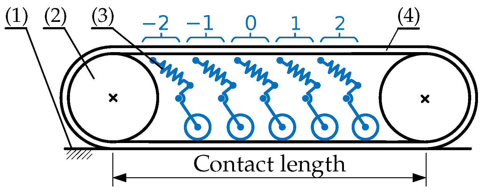
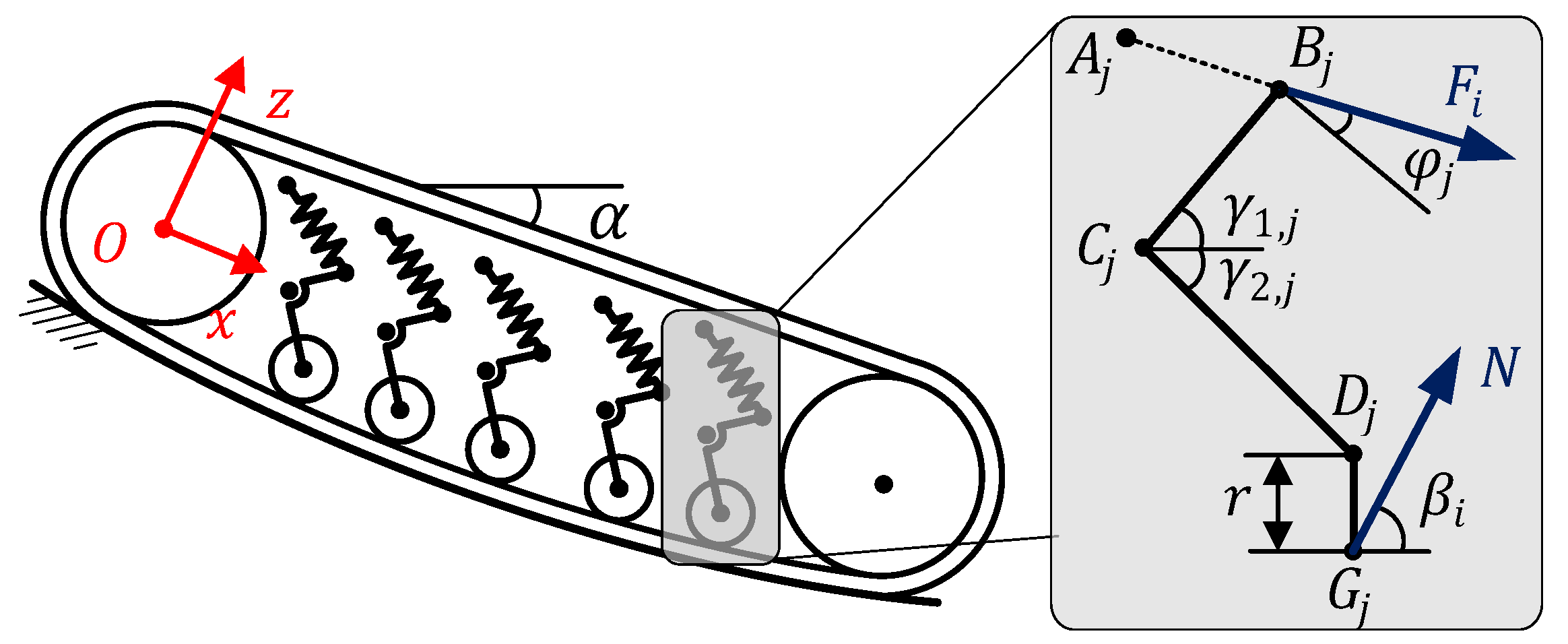
Figure 1 illustrates the kinematic diagram of a track-wheeled system in contact with the surface of a PV panel (1). Let j be the index of the suspension units , with the middle suspension unit corresponding to . The track-wheeled system comprises two timing pulleys (2), a multi-suspension unit (3), and a Polyurethane (PU) endless timing belt (4). The motion is powered by a brushless direct current motor, which drives one timing pulley through the PU timing belt, resulting in the rotation of the other. The contact area between the track-wheeled system and PV panels is defined as the surface area of the PU timing belt limited by the two timing pulleys. The multi-suspension unit is integrated into the track-wheeled system to ensure proper contact between the PU timing belt and the PV panels. Additionally, the multi-suspension unit serves to suppress vibrations induced by the brushing action, as well as vibrations caused by the movement of the SPCRs on the panel support during operation.

Figure 1.
Kinematic diagram of track-wheeled system.
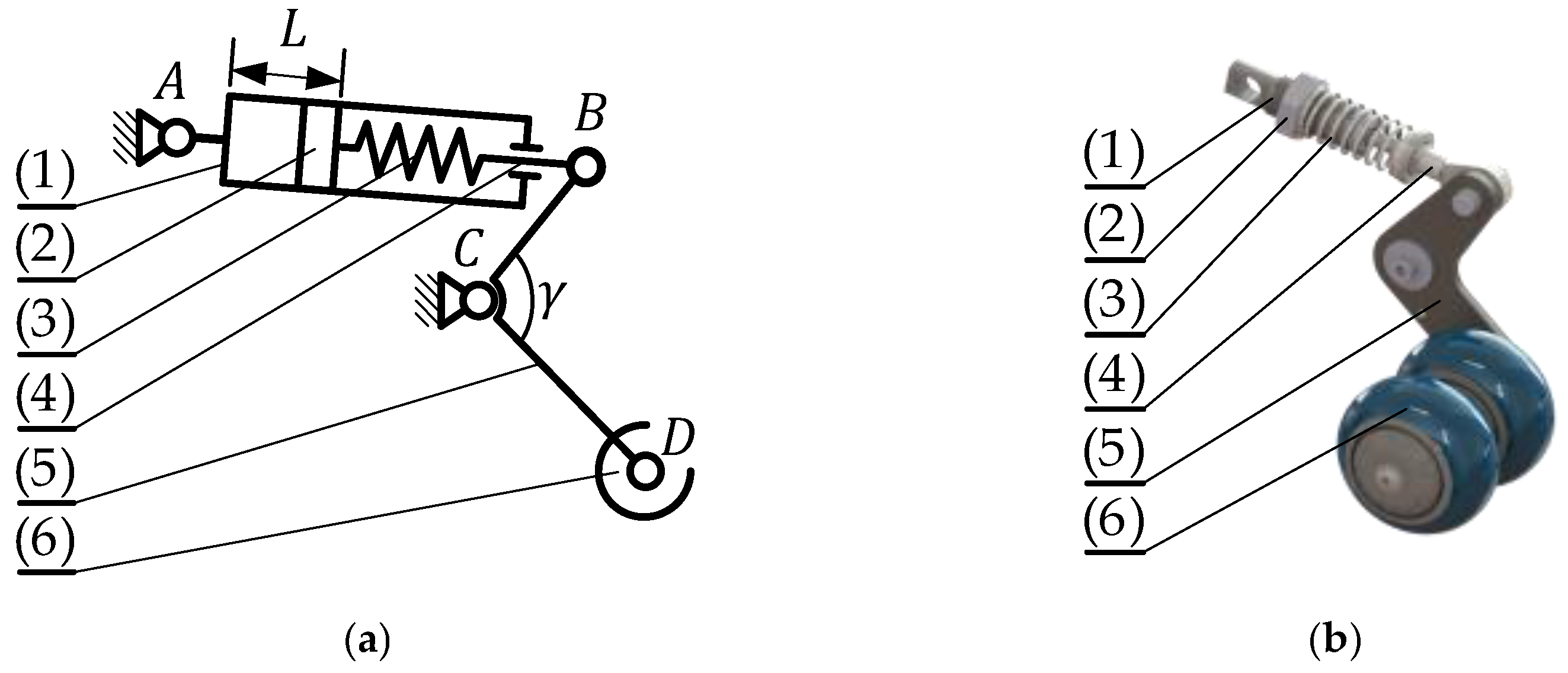
The multi-suspension unit proposed in this paper integrates five suspension units, each with its typical kinematic diagram, as shown in Figure 2a. Each suspension unit comprises an elbow-shaped bogie arm (5) with an angle , a freewheel (6), and a shock absorber. The shock absorber is constructed using a slide tube (1), a bolt nut (2), a compressed spring (3), and a piston rod (4). All five suspension units are mounted to the whole frame at point A, serving as their rotary center. The bogie arm is connected to the shock absorber at point B and the freewheel at point D, allowing it to leverage point C and apply pressure to the freewheels, ensuring proper contact with the PU timing pulley. Considering the potential variations in the altitude of freewheels due to PV panel deformation, the compressed springs can be adjusted using a spring adjuster mechanism inspired by [15]. By sliding the bolt nut along the slide tube, the displacement of the compressed springs can be changed, enabling adjustable spring stiffness. Figure 2b illustrates the 3D CAD design of the suspension, utilizing two freewheels to coincide and spread the entire width of the PU timing belt.
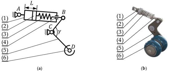
Figure 2.
Kinematic diagram and 3D CAD model of a single suspension unit: (a) kinematic diagram; (b) 3D CAD model.
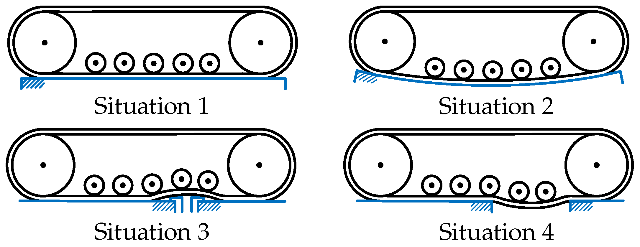
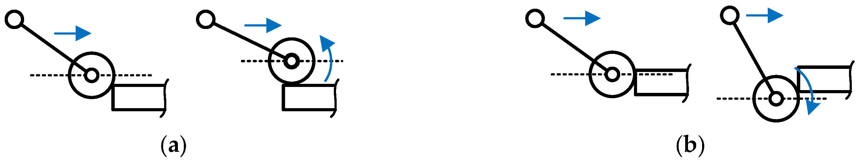
Generally, four situations might occur as SPCRs move on PV panels, as shown in Figure 3. First, the SPCR moves on PV panels with minimal deformation, resulting in the freewheels’ altitude being roughly the same. The second situation defines the largest deformation of PV panels, where the altitude of these wheels is noticeably different. The third situation illustrates the SPCR moving across the mounting clamps or encountering PV panel misalignment, defining the highest travel of the freewheel. In the final situation, the SPCR moves across the gap between two adjacent PV panels, defining the lowest travel of the freewheel.
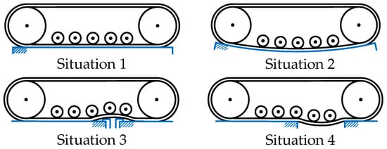
Figure 3.
SPCR movement situations.
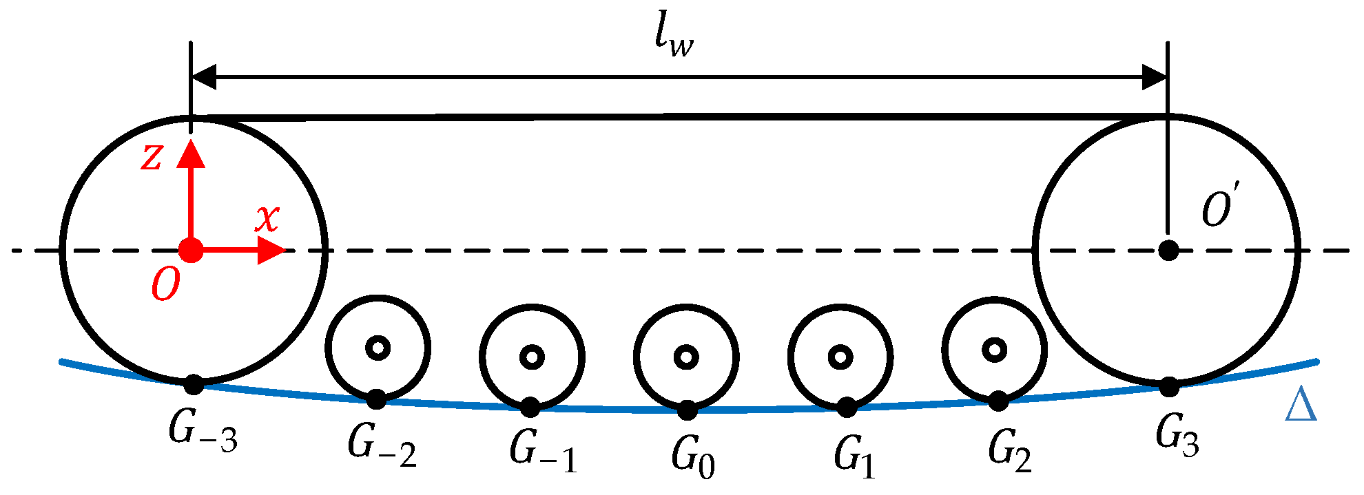
According to [12], situation 2 commonly occurs when the SPCR passes over PV panels along its long edge. For the sake of simplicity, the design process for the multi-suspension unit is implemented by defining multiple contact points between the deformed PV panel and the multi-suspension unit, taking into account the two timing pulleys with the assumption of negligible timing belt thickness, as shown in Figure 4. It is assumed that the track-wheeled system is in contact with the PV panel along the center line. Let (where i is the index ranging from −3 to 3) represent the contact points of the freewheels and the two timing pulleys with the deformed PV panel. Point is the contact point of the middle freewheel, while the other contact points are located on both sides of and spread throughout the contact area. Ideally, these contact points should align on the same line, referred to as basis contact points, when the track-wheeled system is in contact with an undeformed PV panel, and the PU timing belt thickness is uniform.
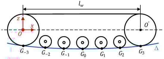
Figure 4.
Multi-contact points between track-wheeled and deformed PV panel.
To describe the altitude of the freewheels, a coordinate system named is assigned at the center of the primary timing pulley. Let the curve represent the deformed profile of PV panels under the weight of SPCRs in the coordinate, defined as a polynomial function with the degree as follows:
where represents the deformation of PV panels, while x denotes the position along the center line of the PV panel in the coordinate. The coefficients of the polynomial, , are determined through least squares interpolation using experimental or simulation data. The degree of the polynomial depends on the level of correlation between the actual data and the fitting curve. Furthermore, it can be seen from Figure 4 that the curve passes through all contact points , disregarding the PU timing belt thickness.
Figure 5 illustrates the altitude of the freewheels corresponding to situations 3 and 4. When the SPCR crosses the gap, the freewheel attains the lowest altitude, corresponding to the natural length of the compressed spring, as shown in Figure 5a. Conversely, when the freewheel passes over a mounting clamp, it reaches the highest altitude, resulting in the shortest length of the compressed spring, as shown in Figure 5b. Let represent the lower maximum displacement of the contact point from its basis position, while represents the upper maximum displacement of the contact point from its basis position. These and values determine the working area of the suspensions, thus influencing the design process of the shock absorber.
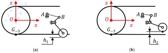
Figure 5.
Displacement of the freewheel in situations: (a) The lowest altitudes; (b) the highest altitudes.
The value is determined to ensure that when the SPCR passes over the gap between two adjacent PV panels the center of the freewheel remains higher than the surface of the next PV panel, allowing for a successful recovery of the freewheel, as shown in Figure 6a. On the contrary, if is inadequate, the freewheel might fail or get damaged during the crossing, as illustrated in Figure 6b. Similarly, determining the value of depends on the installation structure of the PV panel array, as it is directly related to the height of obstacles such as mid-clamps, end-clamps, and end-caps. However, a higher value results in a longer travel distance for the shock absorber.
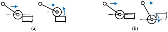
Figure 6.
Displacement of the freewheel in situations: (a) The lowest altitudes; (b) the highest altitudes.
Table 2 presents the parameters of the single suspension unit that have been determined and obtained during the design process. Several factors were considered in this process, including the weight of the SPCR (m), the radius of the freewheel (r), the radius of the timing pulley (R), the distance between the centers of the two timing pulleys (), and the tilt angle of PV panels relative to the ground (). The symbols , , , and represent the connected points of the j-index suspension unit, as described in Figure 2.
Table 2.
Parameters for the design process of single suspension unit.
For the sake of simplicity, the following assumptions are necessary for the design process.
- (1)
- As the SPCR passes over the center point of the PV panels, it induces the largest deflection at this point. Therefore, we assume that the contact point coincides with this point, defined as the lowest altitude of in situation 2, without loss of generality;
- (2)
- The structural parameters of the suspensions are assumed to be the same, so the design process of the middle suspension unit can be applied to the others. The connected points and are initially configured with the same position referring to the z-axis;
- (3)
- The weight of the SPCR is assumed to be evenly distributed on the track-wheeled. Then each track-wheeled is affected by half the weight of the SPCR;
- (4)
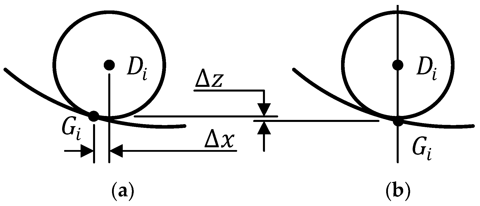
- The contact point is determined as the intersection of the curve and the vertical line passing through the center of the freewheel . The horizontal () and vertical () deviations between the contact point in practice and the equivalent model, as shown in Figure 7, are found to be negligible;
 Figure 7. Comparison of contact points: (a) Practice; (b) equivalent model.
 - (5)
- The magnitude of the reaction force at the contact points of the second situation is equal.
3. Design Process of Single Suspension Unit
3.1. Parameters of the Bogie Arm
As mentioned earlier, the bogie arm features the length of and links, the angle , and the two-dimensional position of the connected point C(), which strongly depends on the working limitations of the contact point. It is essential to first determine the range of the contact point corresponding to the lowest and highest altitudes of the freewheel. It is easy to see that the determination of parameters for the middle suspension unit is the simplest. In fact, it can be seen from Figure 8 that the lowest altitude of is the minimum value of the curve , defined as with . As a result, the value of must satisfy the following condition:
where denotes the first-time derivative of the function along with its variable.
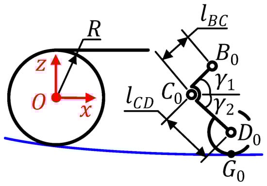
Figure 8.
Design parameters of the bogie arm of the typical suspension unit.
The lowest altitude () and highest altitude () of the center axis of the freewheel are determined as follows:
Let and be the angles formed by the BC and CD links of the suspension unit with the horizontal axis, introducing the constraint , which depends on the position of the freewheel. Referring to [14] about the golden ratio suggested for the design of the tank suspension, denoted as , in this case, the golden ratio defined as the division of the vertical travel of the bogie arm by its length projected to the z-axis. Consequently, the constraint of , , , and is expressed as follows:
It should be noted that the angles and describe the orientation of the middle suspension unit of situation 2. For the preliminary selection of the length and the angle , the coordinates of the connected point are described as follows:
The length of is chosen to ensure that its working area does not extend beyond the mounting space of the track-wheeled. Specifically, the position of the connection point must be ensured not to be higher than the upper side of the timing belt. Considering that the connected point B has the highest position when is 90 degrees, the following inequality should be satisfied:
By substituting the parameters obtained from Equations (3), (5), and (6) into Equation (4), it limits the preliminary selection of parameters , , , and . According to assumption (2), the coordinates of the other rotary joints are determined as follows:
where is the distance between the two adjacent connected points and of the consecutive suspension units.
Figure 9a illustrates the most probable collision scenario for two adjacent suspension units when the freewheels are at their lowest and highest positions, respectively. Applying the theory of plane geometry, the lower limitation of the length must satisfy the condition of Equation (8) to ensure that the collision of two adjacent suspension units does not occur.
where is the largest vertical coordinate of the point . In addition, the length of mounting space of the suspension units (), as shown in Figure 9b, must be less than the free space between the two pulleys (). Consider the case of the freewheels in the highest position, i.e., the extended stroke of the bogie arms exceeds farthest. The upper limitation of the length must then satisfy the following constraint:
where n is the total number of suspension units.
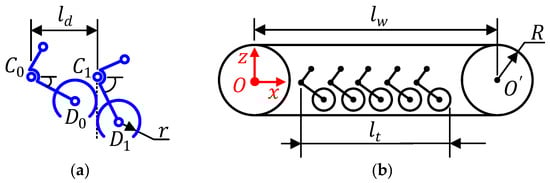
Figure 9.
Design parameters of the bogie arm: (a) the most probable collision scenario for two adjacent suspension units when the freewheels are at their lowest and highest positions; (b) the length of mounting space of the suspension units.
3.2. Coordinate of Connected Point A and Length
Referring to assumption (2), determining the coordinates of connection point A at any suspension unit is sufficient to achieve the coordinates for all other connected points A. Because the parameters of the middle suspension unit are clearly defined in the preceding sections, it is treated as a representative position to design connected point A in this section.
The location of connection point A is determined to satisfy the following two conditions:
- The operation of the bogie arm produces the greatest reaction at the freewheel;
- The coordinates of point A are in the mounting area of the track-wheeled.
In the first condition, the highest reaction force at the freewheel occurs when the moment of the center C is at its maximum. To achieve this, the direction of the spring compression force vector must be perpendicular to the link. Therefore, it is necessary to form the link to be perpendicular to the link within the working area of the bogie arm. Additionally, this ensures that the angle remains at approximately 90 degrees even when the bogie arm is in other positions, thereby maximizing the moment magnitude.
In the second condition, the location of connection point A must be guaranteed to be below the upper branch of the timing belt. Figure 10 illustrates the case where the position of A has satisfied two conditions, i.e., the moment at which the link is perpendicular to the link (1st condition) and A is in the mounting area (2nd condition). Let the length be the distance from the connected point on the whole frame to the connected point on the bogie arm. It is equivalent to the sum of the compression spring length, the length of the slide tube, and the piston rod. Applying the theory of plane geometry to Figure 10, the following inequality must occur:

Figure 10.
Position of connected point A on the track-wheeled.
The angle specifies the position of the bogie arm such that the angle is equal to 90 degrees. The value of is the vertical coordinate of determined through the constraint with the connected point using the following equation with the index ():
Substitute Equation (11) into Equation (10) to specify the preliminary of and . The coordinates of the point are determined as follows:
The coordinates of connected points A belong to the other suspension units are determined as follows:
Determination of the coordinates of the other points A using Equation (13) ensures that the second condition remains satisfied in the remaining suspension units. Furthermore, the first condition is guaranteed due to the bolt–nut adjustment.
The motion of the freewheel represents the working area of the single suspension unit. Therefore, the length was calculated based on the position of the freewheel as follows:
where is length of the suspension unit. The coordinates of are determined by using Equation (11), in which is calculated as follows:
Note that the method for determining the coordinates of points is presented in Section 3.3 (Equations (19) and (20)).
3.3. Determine the Force Exerted by Compressed Spring
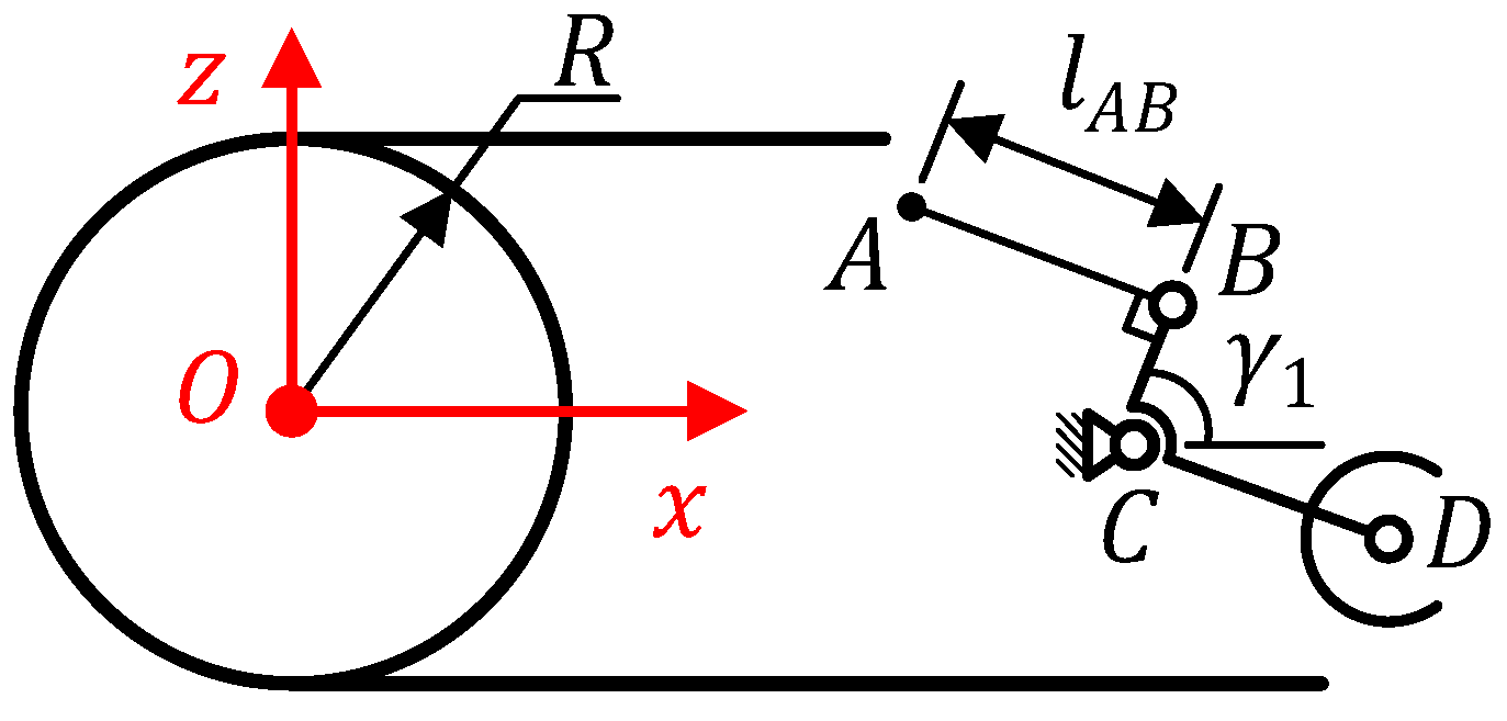
Let be the force exerted by the compressed spring on the bogie arm of the suspension units. Figure 11 illustrates the free-body diagram of the single suspension unit. Note that the reaction at connected point C is not shown because it is not necessary to take it into account. Let be the reaction force exerted by the PV panel on the freewheel at the contact point, and be the angle formed by the reaction and the x-axis at the contact point .
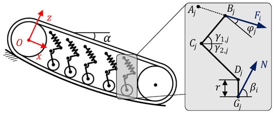
Figure 11.
Free body diagram of the suspension.
The equation to determine the force is described as follows:
According to Newton’s third law, assumptions (3) and (5), the reaction force N is determined as follows:
where g has a value of 9.81 m·s−2, which is the gravitational acceleration.
By considering the dot product between the unit vector of the x-axis (1, 0) and the direction vector of the tangent line equation to at point , the angle is calculated as follows:
On the other hand, the coordinates of the connected point are determined based on the coordinates of the contact point as follows:
Based on the orbital equation of point (circle with center and radius ) combined with Equation (18), the equation to determine is described as follows:
The horizontal coordinate of the contact point is the real solution of Equation (20) and located on the right-hand side of the point in the coordinate system. The vertical coordinates of the contact points are determined by substituting into Equation (1). Based on the coordinates of connected points and calculated at Equations (7) and (19), the angle is determined as follows:
3.4. Parameters of Compressed Spring
The compressed spring is designed for the middle suspension unit; however, the given parameters are still valid for the other suspensions. The spring stiffness, k, is determined based on the spring deflection when the freewheel of the middle suspension is in the contact point (situation 2) relative to the compressed spring at its natural length (situation 4). This deflection is calculated by the change in the length of the link, as follows:
where and are the lengths , with the superscript and respectively stand for situation 4 and situation 2 (shown in Figure 3), of connected point . Specifically, is calculated by substituting and of Equation (3) into Equations (13) and (14). Similarly, also is calculated by substituting and of Equation (2) into Equations (13) and (14).
According to Hooke’s law, the spring stiffness k is calculated as:
where is the elastic force with .
The mean coil diameter is determined as follows:
where d is the wire diameter, Z is the preferred value for the spring index. The values of d and Z are chosen according to [16]. The number of active coils is determined as follows:
where GPa is the shear modulus of steel. The natural length of the spring () is determined by the sum of the spring length at maximum compression and its deflection,
where with . Preliminary selection is the additional value to compensate for the spring gaps when it is maximally compressed; the value is equal to the difference between the length of the middle suspension unit corresponding to situations 3 and 4.
The adjustment range (L), as shown in Figure 1, is calculated as follows:
where is the natural length of the shock absorber. Specifically, the point coordinates of the suspension units are determined by Equations (19) and (20) combined with Equation (15) to determine the angles . The value of angles are substituted into Equation (11) to calculate the coordinates of all connection points in situation (2). Using Equation (14) with the position of to determine the length of links. If this occurs ( or ), the length of the link is necessary to recompute. Finally, the process of designing the multi-suspension unit is summarized into a flow chart and described in Figure 12. It should be noted that the parameters with blue text format are values that need to be determined or preliminarily selected.
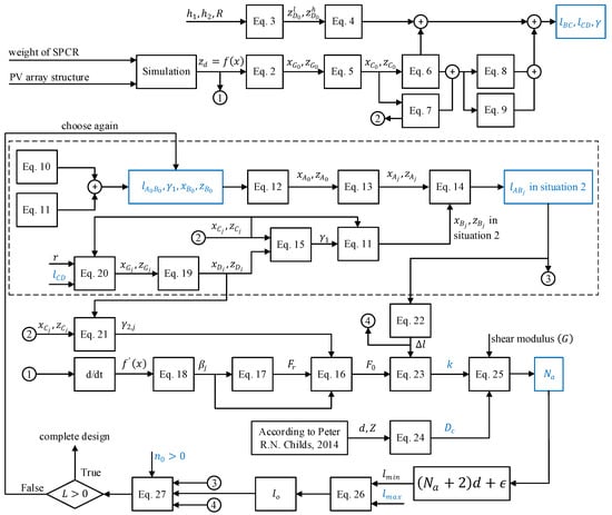
Figure 12.
Flow chart describing the process of designing the multi-suspension unit ([16]).
4. Implementation of Design
4.1. Determine PV Panel Deformation
The coefficients and polynomial order described in Equation (1) are determined through simulations using the Finite Element Method (FEM) in ANSYS. This analysis is conducted with the RD320TU-36MD PV panel, as detailed in Table 3, which incorporates two primary bearing components [17,18,19,20]. Besides, Table 4 describes the necessary settings and limitations of the physical model of the simulation. Based on the simulation data, the curve is estimated using least squared interpolation. The correlation coefficient is employed as a metric to validate the proper degree of the polynomial order.
Table 3.
Material properties of photovoltaic panel components.
Table 4.
Physical model parameters and simulation limitations.
The design of the SPCR is based on the common structure of SPCR [21], with parameters including a timing belt width of 75 mm, timing belt length of 500 mm, and weight of 90 kg. Table 5 describes the interpolation equations and their correlation coefficients () with respect to the simulation results, for which the second orders interpolation equation is used for the design process.
Table 5.
Parameters for design process of single suspension unit.
4.2. Design of Multi-Suspension Unit
In reference to Section 3.1, the values of and are set to 34 mm and 10 mm, respectively. These dimensions are based on the typical PV array installation structure observed in Vietnam. To satisfy Equation (4), angles and were chosen as 55.6 and 44.4 degrees, and corresponding link lengths and are detailed in Table 6. Consequently, the coordinates of the connecting point , as determined by Equation (5), are (257.13, −9.18). In line with Section 3.2, the positioning of to be perpendicular to is selected when the freewheel is in its highest position, taking into consideration the available installation space for the SPCR at the study site.
Table 6.
Parameters of multi-suspension unit after design.
In Section 3.3, the reaction force is determined to have a value of 63.06 N. By substituting Equations (18) to (21) and into Equation (16), the force can be derived. The value of (with ) along with Equation (22) is used in Equation (23) to determine the spring stiffness. The Z value is chosen as 9.5 [16], from which the spring parameters are determined.
Table 6 outlines the parameters of the multi-suspension unit, crafted through the design process. Table 7, on the other hand, delineates the adjustment range, denoted as L, for the shock absorber. The specific value of mm is selected, taking into account the installation space available for the SPCR in the study area. Once the design parameters are established, the model for the multi-suspension unit is fabricated, assembled, and integrated with the track-wheeled SPCR, as depicted in Figure 13.
Table 7.
Adjustment range L of the shock absorber.
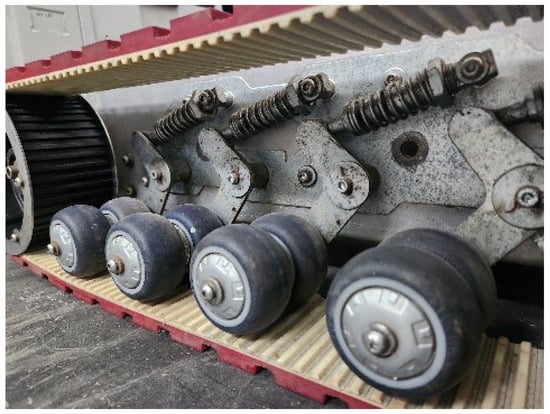
Figure 13.
The multi-damper unit of PV panel cleaning SPCR.
5. Experiment Setup
The tests were carried out using the SPCR with and without the installation of a multi-suspension unit to evaluate the effectiveness of the proposed design. The SPCR, weighing 90 kg, was equipped with two track-wheeled systems, each having a width of 75 mm, and it was observed that the robot can function adequately with or without the multi-suspension unit. The induced vibration is likely caused by mechanical deviations arising from structural misalignment, machining tolerances, and asymmetrical components during the robot assembly process, as well as certain levels of elasticity and flexibility exhibited by PV panels. It is anticipated that the multi-suspension unit may assist in reducing the deflection of PV panels not only during brush rotation but also during the movement of the entire SPCR. Therefore, it is necessary to individually investigate these situations. To validate the effect of solely brush rotation on PV panel vibration, a configurable PV module, as depicted in Figure 14a, with a single PV panel fixed to the rack at a 10 degrees tilt southward along its short edge, was employed. The SPCR was positioned stationary on the PV module while the brush was rotating to observe the effect on PV panel vibration. Furthermore, the vibration caused by the SPCR during full operation, i.e., while passing over PV arrays with the brush rotating, was evaluated for landscape and portrait PV modules. The former, illustrated in Figure 14b, consists of three PV panels arranged in a single row with their short edges aligned, forming a horizontal profile. The latter configuration, shown in Figure 14c, consists of two PV panels connected in a series along their long edges, introducing a vertical profile. All PV module configurations were constructed in accordance with the standard [22] to replicate practical PV modules, aiming to observe their true behavior.

Figure 14.
Configuration of PV module to investigate the effect of the multi-suspension unit: (a) single PV panel to investigate the impact of solely brush rotating; (b) three PV panels constructed into landscape PV module to investigate the impact of multi-damper unit during SPCR operation; (c) two PV panels connected in series to investigate the impact of multi-damper unit during SPCR operation.
The deflection of PV panels was measured using an instrument, as shown in Figure 15. This instrument consists of a Mitutoyo 543-400B round-type dial gauge (DG) with a resolution of 0.01 mm, which is attached to a magnetic base stand. This configuration allows for easy positioning and orientation of the DG perpendicular to the PV panel surface. Care was taken to ensure that the tip of the DG made contact beneath the backside of the PV panels without scratching the module’s back surface. The deflection values were recorded using a computer connected to the DG via a transmission cable.
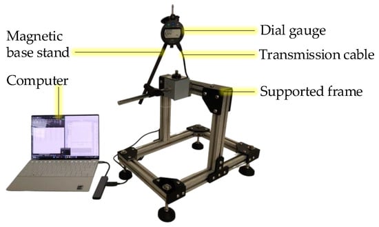
Figure 15.
Dedicated instrument for deflection measurement.
All tests solely focused on the impact of the SPCR being in operation on the vibration of PV panels. Thus, external factors such as windy conditions, earthquakes, or other fluctuations were prevented from influencing the experiments. In addition, the PV panel support frame is designed to be rigid, and its deformation during the experiment is negligible. The speed of the SPCR was controlled to move at approximately 20 m·min−1, and it was recognized that the speed of the brushes could significantly affect the vibration. Therefore, the determination of the brushes’ rotating speed was based on the Nyquist–Shannon sampling theorem. As a result, the sampling frequency () of the logged deflection values had to satisfy the following inequality:
where is the angular velocity of the brushes. For the angular velocity of brushes , the sampling period is defined as should be less than 0.15 s. Therefore, the chosen sampling period is 0.1 s.
To assess the effectiveness of the multi-suspension unit in reducing the vibration amplitude of the PV panel across all experimental data, we introduced a metric called deflection deviation (). This metric quantifies the change in deflection per unit of time. A large value indicates a significant and sudden change in deflection at that moment, while a small value suggests a more stable deflection pattern. The metric is defined as follows:
where and are deflections of the PV panel sampled at the times t and .
6. Results and Discussion
6.1. Impact of Rotating Brushes on Vibration
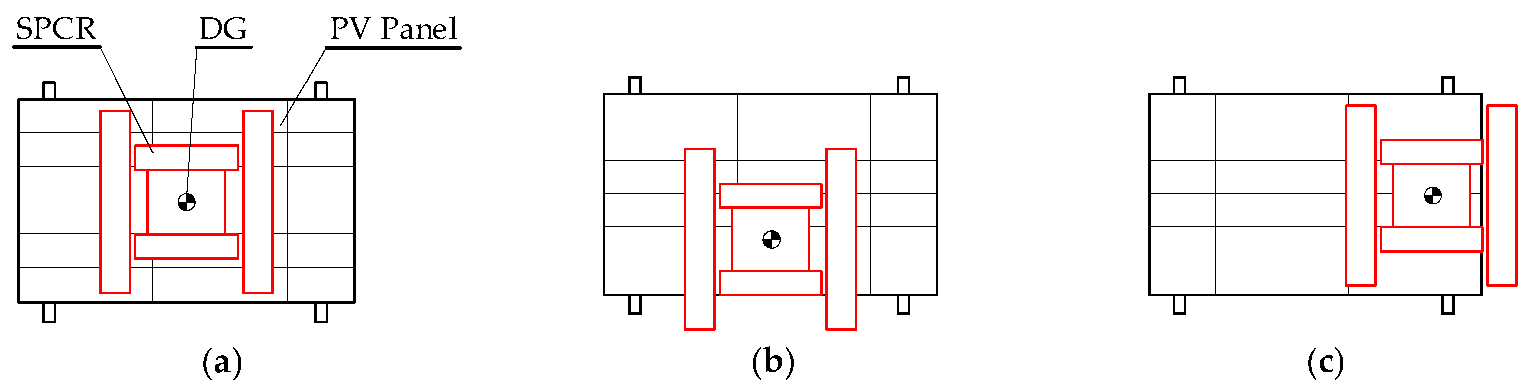
The vibration of the PV panel is affected by its elasticity when subjected to the excitation of rotating brushes. To evaluate the PV panel’s response-induced vibration, the SPCR was intentionally stopped while the brushes continued to rotate. The robot was then placed at various locations on the PV panel, including the center (Figure 16a), along the long edge (Figure 16b), and close to the short edge (Figure 16c).
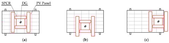
Figure 16.
Placement of SPCR on PV panel to investigate the effect of the multi-suspension unit on vibration with solely rotating brushes: (a) At the middle of PV panel; (b) At the middle of the PV panel’s long edge; (c) At the middle of the PV panel’s short edge.
Deflection measurements were taken using the DG placed beneath the PV panels, aligning with the SPCR’s center. Figure 17 displays the raw data depicting PV panel deflections induced by the SPCR’s rotating brushes, both with and without the multi-suspension unit. When the SPCR was centered (Figure 17a), along the long edge (Figure 17b), and near the short edge (Figure 17c), peak deflection values of the PV panel without the multi-suspension unit were observed to be 1.65 mm, 1.79 mm, and 0.29 mm, respectively. In contrast, with the multi-suspension unit equipped on the SPCR, the corresponding deflection values reduced to 0.55 mm, 0.49 mm, and 0.19 mm. In these experiments, the influence of the SPCR’s mass on the PV panel is not taken into account, as they focus solely on stationary conditions. Therefore, it is essential to note that these deflection values exclude the initial deformation caused by the SPCR’s mass affecting the PV panel. The variation in deflection mainly stems from variations in the strength of the PV panels at different positions. Specifically, the PV panels demonstrate greater resistance to deformation near the strength-supporting bar, such as the short edges. Consequently, deflections are lower when the SPCR is positioned near the short edge of the PV panel. Furthermore, the mass of the SPCR is not evenly distributed across the entire aluminum frame but is concentrated predominantly along the long edge of the PV panel. As a result, significant deformation occurs in the photovoltaic panel when the SPCR approaches its long edge.
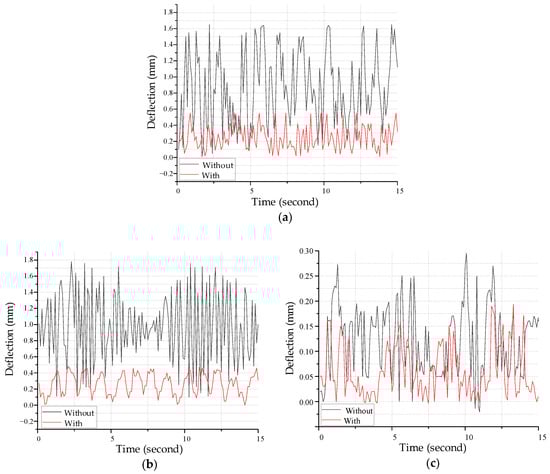
Figure 17.
Raw data of PV panel deflection under rotating brushes: (a) SPCR placed at the center of the PV panel; (b) SPCR placed along the long edge of the PV panel; (c) SPCR placed at the short edge of the PV panel.
The effectiveness of the multi-suspension unit in reducing peak deflection exhibited a significant reduction of 66.67%, 72.63%, and 34.48% compared to the case without using the multi-suspension unit when the SPCR was positioned at the center, along the long edge, and in close proximity to the short edge, respectively. These results reveal a gradual decrease in the multi-suspension unit’s efficacy as the SPCR’s position moves to areas with lower PV panel deformation. This phenomenon can be attributed to the compressed spring experiencing substantial deflection, leading to increased compressive force when the SPCR is located in regions with less PV panel deformation. Moreover, the compressive strain of the rubber tank track pads is directly affected by the reaction force from the freewheels, resulting in greater compression as the SPCR approaches the short edge of the PV panel. Consequently, this reduces the damping ratio [21] of the multi-suspension unit and subsequently diminishes its vibration absorption capability [22]. It is worth noting that the reduction in the effectiveness of the multi-suspension unit when the SPCR is situated at the short edge of the PV panel is relatively minor in the SPCR’s overall operation.
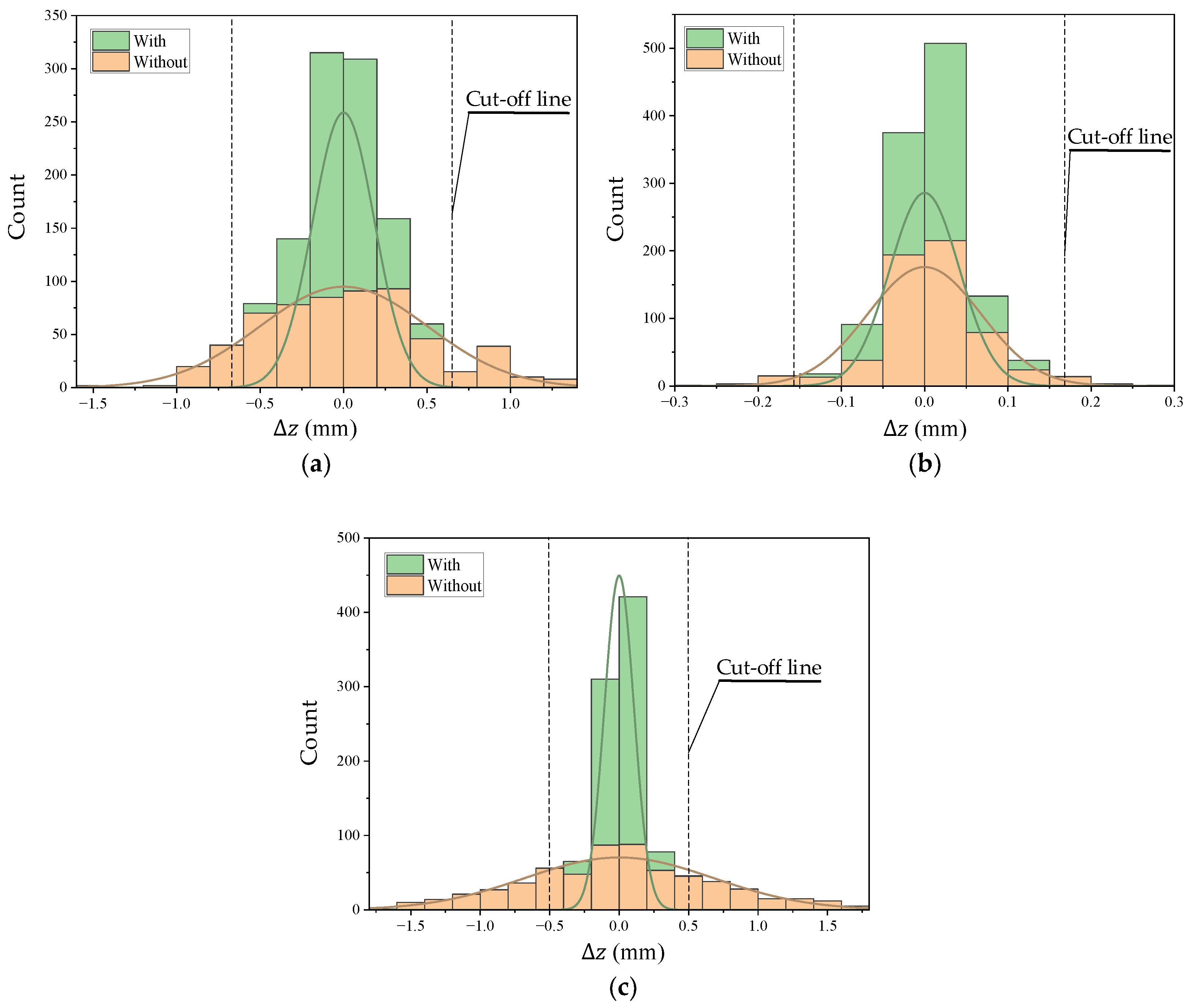
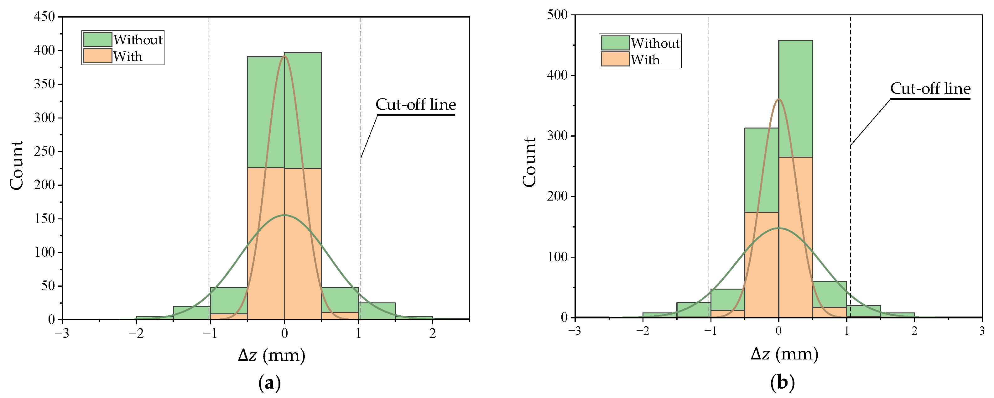
Figure 18 displays the variation in values during a 45-s experimental period, comparing the SPCR with and without the integration of the multi-suspension unit at different positions on the PV panel. The results reveal a substantial reduction or even the absence of many significant values (exceeding 0.5 mm) when the SPCR is equipped with the multi-suspension unit, particularly when positioned at the center (Figure 18a) or the long edge (Figure 18c) of the PV panel. It is noteworthy that the count of smaller values (below 1.0 mm) increases, appearing to the left of the cut-off line. This implies that while the multi-suspension unit does not entirely eliminate vibrations, it effectively reduces their amplitude. Moreover, the placement of the cut-off line significantly determines the extent of vibration reduction. Specifically, the ratio between the distance separating the two cut-off lines and the width of the horizontal axis is inversely related to the level of vibration. Placing the SPCR at the long edge of the PV panel results in the most effective vibration suppression. In contrast, when the SPCR is positioned near the PV panel’s short edge, close to the supporting bar, the difference in the count of significant values between the SPCR with and without the multi-suspension unit becomes negligible, as depicted in Figure 18b. This observation indicates that the multi-suspension unit strongly influences vibrations characterized by larger amplitudes.
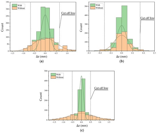
Figure 18.
Variation of deflection deviation with SPCR stopped, yet brushes rotating on different positions of PV panel: (a) at the center of the PV panel; (b) at the short edge of the PV panel; (c) at the long edge of the PV panel.
6.2. Impact of SPCR Operation on Landscape PV Module
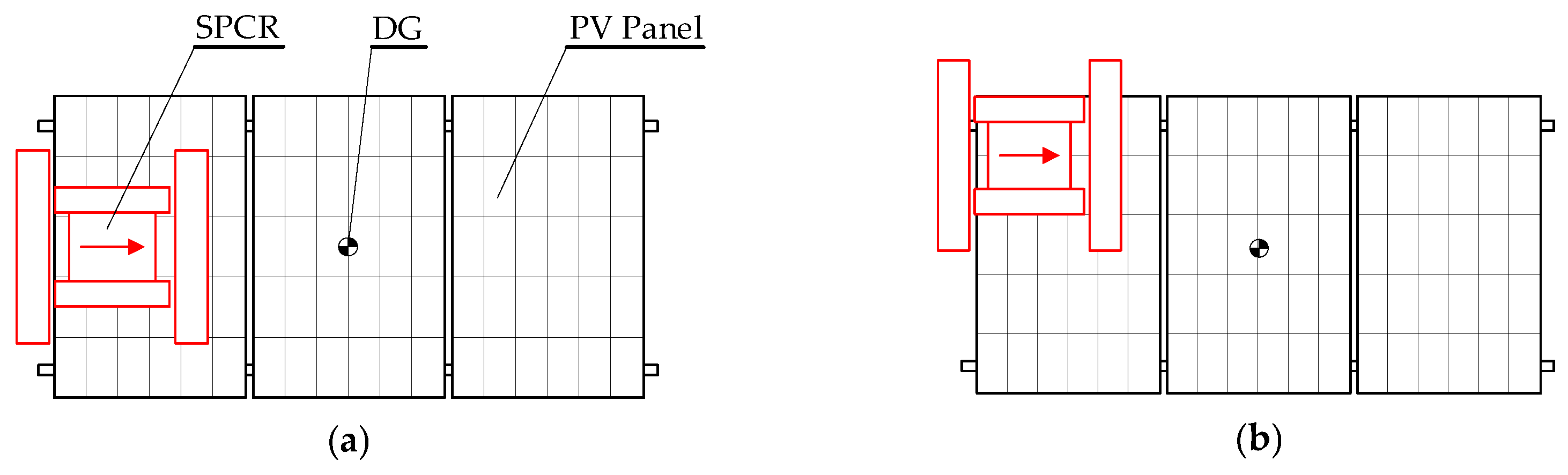
The results above indicate that the vibration degradation varies depending on the placement of the SPCR. To further investigate, the SPCR was planned to pass over the PV module along the center (Figure 19a) and the upper side of the PV panels (Figure 19b). The dial gauge (DG) was positioned to measure the deflection of the middle PV panel, capturing vibrations before the SPCR entered and after leaving the PV panel.
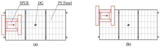
Figure 19.
Investigation of vibration caused by SPCR operation on landscape PV module: (a) SPCR passes over the module along the center of the PV panels; (b) SPCR passes over the module along the side of PV panels.
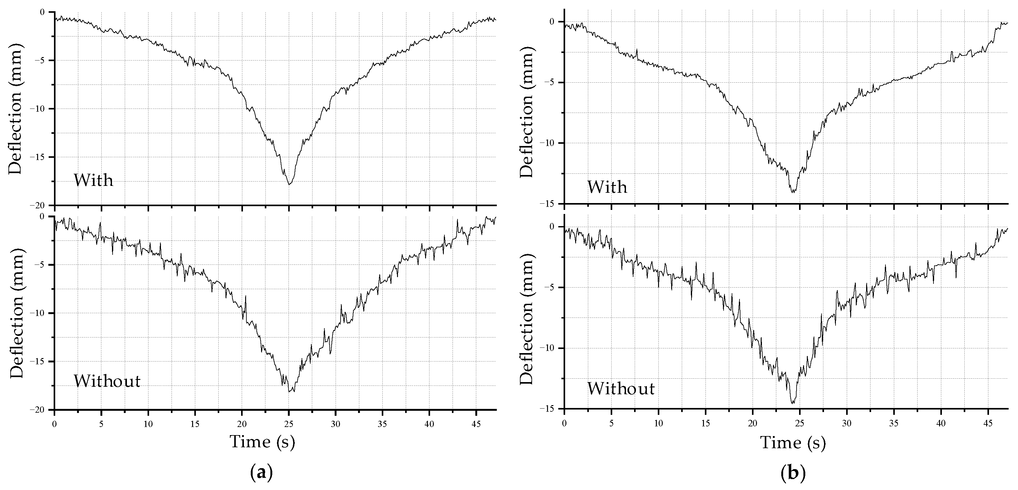
Figure 20 illustrates the deformation of the PV panel under the passage of the SPCR with/without the installation of the multi-suspension unit along the center and upper side of the PV panels. As the SPCR passed over the center of the PV panels, it induced peak deflections of 18.16 mm and 17.86 mm, respectively, for the SPCR equipped with and without the multi-suspension unit. Similarly, when the SPCR passed over the PV panels along their sides, peak deflections of 14.58 mm and 14.08 mm were observed, respectively. It is noted that the impact of SPCR operation is considered, so the experimental results encompass the effects of rotating brushes and the PV panel deformation caused by the mass of the SPCR.
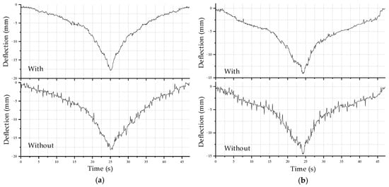
Figure 20.
Raw data of PV panel deflection under SPCR operation on the landscape PV module: (a) SPCR moves in the center of the PV panel; (b) SPCR moves at the edge of the PV panel.
These findings align with the conclusion that the reduction in vibration is less pronounced when the SPCR is positioned closer to the supporting bar. With the inclusion of the multi-suspension unit, the peak deflection decreased by approximately 1.65% (when located along the center) and 3.43% (along the upper side). Figure 20 indicates that the maximum deflection occurs around 25 seconds when the SPCR traverses over the central PV panel. Both before entering and after leaving the central PV panel, the SPCR still induces deformation and deflection on the panel. Moreover, it is evident that the SPCR, equipped with the multi-suspension unit, significantly dampens the vibration amplitude, resulting in the absence of noticeable vibration spikes.
Figure 21 illustrates the variation in values during the 45-s experimental period as the SPCR passes over the landscape PV module. The experiment was conducted both with and without the installation of the multi-suspension unit, considering paths along the center and upper side of the PV panel. Irrespective of the SPCR’s trajectory, the results clearly demonstrate a substantial reduction in significant values (exceeding 1.0 mm) when the multi-suspension unit is employed. For instance, as the SPCR moves along the center of PV panels, values larger than 1.0 mm are completely suppressed. At the same time, the value from 0 to 0.5 mm increases from 172 counts to 223 counts. Referring to the results of the stationary SPCR case, the position of the cut-off line, which signifies the level of vibration suppression, is influenced by the vibration amplitude of the PV panel. Given the relatively consistent vibration amplitudes in both experimental scenarios, the cut-off line position remains roughly similar. A noteworthy observation was the symmetric distribution of deflection deviations around zero. This suggests that deflections occur uniformly and cyclically across the PV panel.
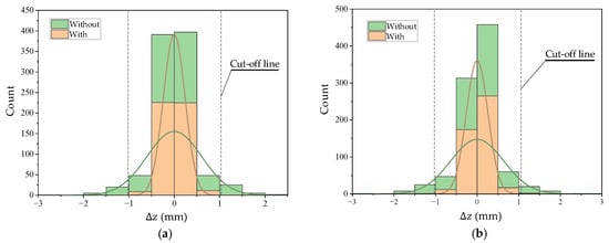
Figure 21.
Variation of deflection deviation under SPCR operation on the landscape PV module: (a) SPCR passes over the module along the center of PV panels; (b) SPCR passes over the module along the side of PV panels.
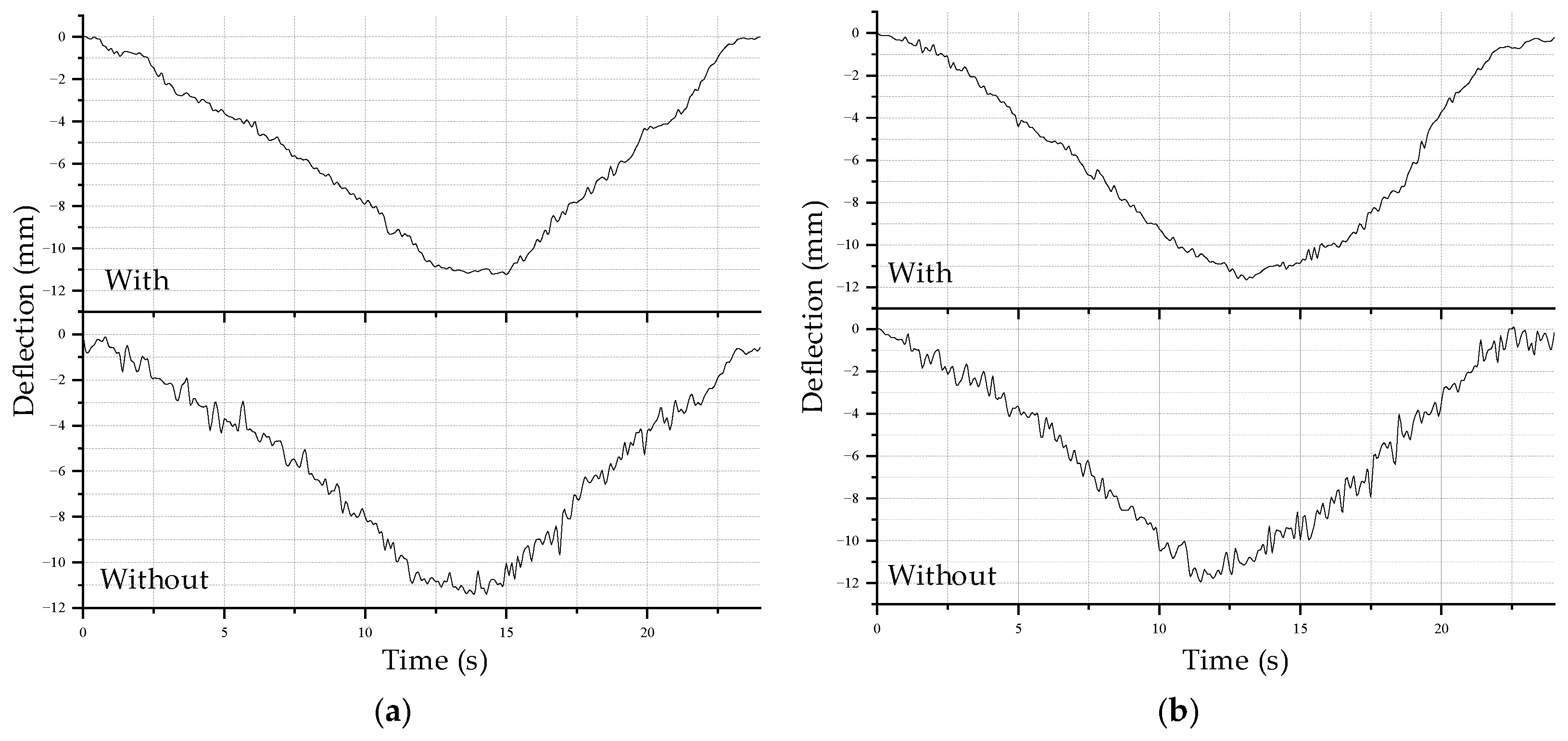
In these scenarios, the SPCR was planned to pass over the portrait PV module along the center (Figure 22a) and the upper side of the PV panels (Figure 22b). The DG was positioned to measure the deflection of the second PV panel. Figure 23 depicts the deflection of the PV panel with and without the installation of the multi-suspension unit as the SPCR passes over the portrait PV module. Without the multi-damper unit, the SPCR caused peak deflections of 11.65 mm (along the center) and 11.88 mm (along the upper side) of the PV panel, whereas, with the presence of the multi-damper unit, these values were reduced to 11.40 mm and 11.23 mm, respectively. These values account for the initial deformation due to the SPCR’s mass acting on the PV panel. The installation of the multi-suspension unit resulted in peak deflections caused by the SPCR being reduced by 2.15% and 5.47%, respectively. Similar to the previous scenario, the effect of the multi-suspension unit in decreasing peak deflections during the operation of the SPCR is negligible. Additionally, the largest deformation occurs when the SPCR moves near the long edge of the PV panel, which is consistent with the tests of the SPCR stoppage.
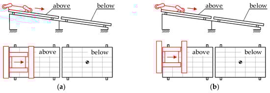
Figure 22.
Variation of deflection deviation under SPCR operation on the portrait PV module: (a) the SPCR passes over the portrait PV module along the center of the PV panels; (b) the SPCR passes over the portrait PV module along the upper side of the PV panels.
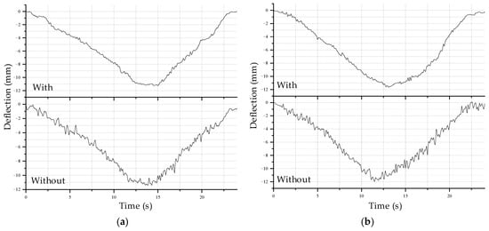
Figure 23.
Experimental results for the dynamic state of SPCR with the PV array installed in landscape orientation: (a) SPCR passes over the module along the center of the PV panels; (b) SPCR passes over the modules along the side of the PV panels.
Furthermore, the distortions occur non-periodically, or the deflection repetition region is very small, and the peak deflection does not occur instantly. This indicates that the deflection occurs more slowly on PV panels compared to other scenarios, resulting in lower fatigue inside the PV glass layer due to the reduced frequency of cyclic loading. The reason for this difference is the distribution of weight force from the SPCR on the PV panels in this scenario, which differs from the previous ones. The SPCR introduces a wheeled track with a smaller width than the timing belt contact length, resulting in a more concentrated force when the SPCR moves along the short edge of the PV panel. Therefore, the PV panels experience minimal deformation in the case of the portrait PV module.
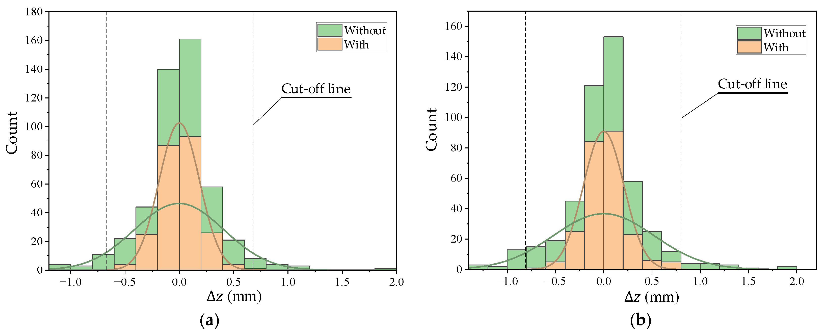
Figure 24 presents a histogram portraying the frequency distribution of values in this experiment. The results reveal a reduction in occurrences of large deflections and a corresponding increase in instances of smaller deflections, highlighting the efficacy of the multi-damper unit, as observed in previous cases. Specifically, as the SPCR moves along the side of the PV panel, has a value of approximately 0.5 mm that decreased from 18 counts to 5 counts. Otherwise, with values around 0 to less than 0.25 mm increased from 61 counts to up to 91 counts. In terms of characteristics, the results demonstrate a general symmetry in both scenarios involving the robot’s exposure to vibrations. However, the values remain relatively modest, spanning from 0.5 mm to 2.0 mm for both cases, with and without the multi-suspension unit. This reinforces the conclusion that the changes in PV panel deflection occur at a slower pace in this specific scenario. Similar to the results for the case in Section 6.2, because vibration amplitudes have approximately equal values in the two experimental scenarios, the location of the cut-off line is almost similar.
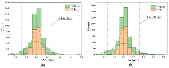
Figure 24.
Variation of deflection deviation under SPCR operation on the portrait PV module: (a) SPCR passes over the module along the center of the PV panels; (b) SPCR passes over the modules along the side of the PV panels.
7. Conclusions
This study presents the design process of a multi-suspension unit equipped with the SPCR to minimize vibrations on PV panels resulting from SPCR oscillations during operation. The proposed approach offers customization, allowing flexibility in design to accommodate different types of PV panels, wheeled track mounting spaces, SPCR weight, and PV array structures. Furthermore, the design’s advantage lies in its compatibility with commercial solar panel cleaning robots, as it can be installed on mobile platforms, facilitating the ease of upgrades and maintenance. The experimental results unequivocally demonstrate the effectiveness of the proposed multi-suspension unit in reducing or eliminating substantial deflections, particularly when dealing with vibrations solely from rotating brushes. However, the proposed design was found to reduce the number of deflection deviations while the vibration frequency remained constant.
For future work, this study will incorporate a mass-spring-damper system, integrating a shock absorber alongside the spring. This enhancement is expected not only to reduce vibration amplitude but to also reduce the vibration frequency of the PV panel. To achieve this, the dynamics based on the Lagrange equation for the multi-suspension unit will be considered to determine the necessary damper coefficient for effective vibration suppression. Alternatively, a novel mechanical design for the shock absorber, capable of regulating the damper coefficient, will be explored to adapt to varying vibrations as the SPCR changes motion. These advancements aim to further enhance the overall vibration mitigation capability of the multi-suspension unit.
Author Contributions
Conceptualization, C.T.T. and N.T.L.; methodology, N.T.L. and V.T.D.; software, N.T.L.; validation, T.D.P., M.D.N. and V.T.D.; formal analysis, T.D.P. and N.T.L.; investigation, H.H.N.; resources, C.T.T.; data curation, T.D.P. and M.D.N.; writing—original draft preparation, N.T.L., T.D.P. and C.T.T.; writing—review and editing, V.T.D.; visualization, M.D.N. and T.D.P.; supervision, H.H.N.; project administration, T.T.N.; funding acquisition, T.T.N. All authors have read and agreed to the published version of the manuscript.
Funding
This research was funded by Vietnam National University Ho Chi Minh City (VNU-HCM) under grant number TX2023-20b-01.
Institutional Review Board Statement
Not applicable.
Informed Consent Statement
Not applicable.
Data Availability Statement
The data presented in this study are available on request from the corresponding author.
Acknowledgments
This research was funded by Vietnam National University Ho Chi Minh City (VNU-HCM) under grant number TX2023-20b-01. We acknowledge the support of time and facilities from National Key Laboratory of Digital Control and System Engineering (DCSELab), Ho Chi Minh City University of Technology (HCMUT), VNU-HCM for this study.
Conflicts of Interest
The authors declare no conflict of interest.
References
- Maka, A.; Alabid, J. Solar energy technology and its roles in sustainable development. Clean Energy 2022, 6, 476–483. [Google Scholar] [CrossRef]
- Sahu, O. Alternative Sources of Energy in Sustainable Development Goals: A Study on Solar Energy. Int. J. Manag. Public Policy Res. 2023, 2, 45–53. [Google Scholar] [CrossRef]
- Jawale, J.; Karra, V.; Patil, B.; Singsh, P.; Singsh, S.; Atre, S. Solar panel cleaning bot for enhancement of efficiency—An innovative approach. In Proceedings of the 3rd International Conference on Devices, Circuits and Systems, Coimbatore, India, 3–5 March 2016. [Google Scholar]
- Saravanan, S.; Darvekar, K. Solar Photovoltaic Panels Cleaning Methods A Review. Int. J. Pure Appl. Math. 2018, 118, 1–17. [Google Scholar]
- Kobrin, B. Self-Cleaning Technologies for Solar Panels. Available online: https://www.ntechresearch.com/wp-content/uploads/2018/05/with-cover-self-cleaning-solar-panels-article-0530.pdf (accessed on 15 September 2023).
- Le, T.; Phan, L.; Nguyen, T. Survey on the Cleaning Method for Solar Photovoltaic Panel. Vietnam Mech. Eng. J. 2023, 299, 45–53. [Google Scholar]
- Gul, R.; Kamran, M.; Zafar, F.; Noman, M. The impact of static wind load on the mechanical integrity of different commercially available mono-crystalline photovoltaic modules. Eng. Rep. 2020, 2, 1–13. [Google Scholar] [CrossRef]
- Papargyri, M.; Theristis, M.; Kubicek, B.; Krametz, T.; Mayr, C.; Papanastasiou, P.; Georghiou, G. Modelling and experimental investigations of microcracks in crystalline silicon photovoltaics: A review. Renew. Energy 2020, 145, 2387–2408. [Google Scholar] [CrossRef]
- Dhimish, M.; Holmes, V.; Dales, M.; Mehrdadi, B. Effect of micro cracks on photovoltaic output power: Case study based on real time long term data measurements. Micro Nano Lett. 2017, 12, 803–807. [Google Scholar] [CrossRef]
- Figgis, B.; Bermudes, V.; Lopez, J. PV module vibration by robotic cleaning. Sol. Energy 2017, 250, 168–172. [Google Scholar] [CrossRef]
- Antonelli, M.; Beomonte, P.; Marcellis, A.; Palange, E. Autonomous robot for cleaning photovoltaic panels in desert zones. Mechatronics 2020, 68, 102372. [Google Scholar] [CrossRef]
- Phan, D.; Nguyen, D.; Auffray, M.; Le, T.; Truong, T.; Duong, T.; Nguyen, H.; Nguyen, T. Research Impact of Solar Panel Cleaning Robot on Photovoltaic Panel’s Deflection. In Proceedings of the 4th International Conference on Applied Convergence Engineering, Ho Chi Minh City, Vietnam, 14–16 August 2023. [Google Scholar]
- Nguyen, T.; Truong, T.; Nguyen, T.; Duong, T.; Nguyen, H.; Nguyen, T. Research on Adhesive Coefficient of Rubber Wheel Crawler on Wet Tilted Photovoltaic Panel. Appl. Sci. 2022, 12, 6605. [Google Scholar] [CrossRef]
- Weeks, J.; Easton, S.; Sword, L. High Travel Suspension for Small Ground Mobile Robots. U.S. Patent 8,875,816, 4 November 2014. [Google Scholar]
- Rau, J. Shock Absorber Spring Adjuster. U.S. Patent 5,044,614, 3 September 1991. [Google Scholar]
- Peter, C. Mechanical Design Engineering Handbook, 1st ed.; Elsivier: Waltham, MA, USA, 2014; pp. 625–675. [Google Scholar]
- Saibabu, P.; Sai, H.; Yadav, S.; Srinivasan, C. Synthesis of model predictive controller for an identified model of MIMO process. Indones. J. Electr. Eng. Comput. Sci. 2019, 17, 941–949. [Google Scholar]
- Srirodpai, O.; Wootthikanokkhan, J.; Nawalertpanya, S.; Yuwawech, K.; Meeyoo, V. Preparation, characterization and thermo-chromic properties of EVA/VO2 laminate films for smart window applications and energy efficiency in building. Materials 2017, 10, 53. [Google Scholar] [CrossRef] [PubMed]
- General Properties of Tedlar PVF Films. Available online: https://www.rowlam.com/documents/DEC_Tedlar_GeneralProperties.pdf (accessed on 15 September 2023).
- Dong, J.; Yang, H.; Lu, X.; Zhang, H.; Peng, J. Comparative Study on Static and Dynamic Analyses of an Ultra-thin Double-Glazing PV Module Based on FEM. Energy Procedia 2015, 75, 343–348. [Google Scholar] [CrossRef]
- Zahedi, R.; Ranjbaran, P.; Gharehpetian, G.; Mohammadi, F.; Ahmadiahangar, R. Cleaning of floating photovoltaic systems: A critical review on approaches from technical and economic perspectives. Energies 2021, 14, 2018. [Google Scholar] [CrossRef]
- Aboagye, B.; Gyamfi, S.; Ofosu, E.; Djordjevic, S. Investigation into the impacts of design, installation, operation and maintenance issues on performance and degradation of installed solar photovoltaic (PV) systems. Energy Sustain. Dev. 2022, 66, 165–176. [Google Scholar] [CrossRef]


Disclaimer/Publisher’s Note: The statements, opinions and data contained in all publications are solely those of the individual author(s) and contributor(s) and not of MDPI and/or the editor(s). MDPI and/or the editor(s) disclaim responsibility for any injury to people or property resulting from any ideas, methods, instructions or products referred to in the content. |
© 2023 by the authors. Licensee MDPI, Basel, Switzerland. This article is an open access article distributed under the terms and conditions of the Creative Commons Attribution (CC BY) license (https://creativecommons.org/licenses/by/4.0/).