Article

The Influence of Supply Channel Design on the Gas-Dynamic Structure of Air Flow in a Vertical Conical Diffuser

by
Leonid Plotnikov
1,* and
Alexander Ryzhkov
2
1
Turbines and Engines Department, Ural Federal University Named after the First President of Russia B. N. Yeltsin, Str. Mira 19, Yekaterinburg 620002, Russia
2
New Energy Technologies Laboratory, Ural Federal University Named after the First President of Russia B. N. Yeltsin, Str. Mira 19, Yekaterinburg 620002, Russia
*
Author to whom correspondence should be addressed.
Appl. Sci. 2023, 13(22), 12141; https://doi.org/10.3390/app132212141
Submission received: 16 October 2023 / Revised: 4 November 2023 / Accepted: 7 November 2023 / Published: 8 November 2023
(This article belongs to the Section Fluid Science and Technology)

Abstract

:
Vertical conical diffusers are used in power engineering, chemical industry, technological processes, and other industries. The efficiency of many machines and pieces of equipment is determined by the gas-dynamic and heat-exchange perfection of processes in diffusers. This study assesses the influence of the air supply method on flow structure in a diffuser. The studies were carried out on a test bench with thermal imaging for air flow rates ranging from 0.018 to 0.057 m3/s (42,500 < Re < 150,000). Two designs were examined: (1) a conventional air supply through one channel from below and (2) a nozzle air supply through four tubes at an angle of 45° to the vertical axis. In addition, the influence of the cross-sectional shape of the supply channels of both designs was studied. It is established that the use of a conventional air supply through one channel leads to the generation of a pronounced central flow along the vertical axis (all configurations of the supply channel) and the creation of stagnant zones in the corners of the diffuser (round and triangular channels; the use of a square supply channel causes the most uniform air distribution throughout the entire volume of the diffuser (while maintaining the central flow). It is found that with nozzle air supply, there are no stagnant zones in the corners and intense air movement generation in the centre of the diffuser (round and triangular tubes) can be observed; the use of square nozzle tubes causes intense flow movement at the base of the diffuser, which quickly collapses upstream, uniformly filling the entire volume of the diffuser’s cylindrical part. The presented data can be useful for designing various machines and pieces of equipment with vertical conical diffusers.

1. Introduction

Conical diffusers (CD) of one design or another are widely used in various technical, technological, chemical, and scientific processes [1]. The gas-dynamic perfection of the flow of air or liquid in a CD largely determines the efficiency of processes in a machine, piece of equipment, or any device [1,2]. Therefore, it is a relevant objective to study the gas dynamics of flows in a conical diffuser and develop methods for controlling the structure of flows in a CD. CDs are exploited in various technical units. Given below are examples of some possible areas of application. Vertical CDs are an integral part of devices for producing synthesis gas from various carbon materials [3,4]. CDs are also used in steam generators to assist in the separation of liquid and air [5]. Conical sections are often found in combustion chamber elements of gas turbines or burners [6]. CDs are exploited to increase the wind speed and efficiency (through energy recovery) of wind turbines [7,8]. CDs are also used in the outlets of organic Rankine-cycle turbines [9]. CDs are widely exploited in hydraulic turbines to increase productivity and efficiency [10,11,12]. There are also other applications where diffusers can be used, namely turbine traction diffusers [13], water pumps [14], and hydrokinetic turbines [15].
Presented below are the results of other authors studying physical processes in diffusers and data on the applied aspects of using CDs in various industries.
Considerable work is being carried out to create models and algorithms for forecasting gas-dynamic characteristics in conical diffusers under various initial conditions [16,17,18,19,20]. For example, A. Ferrari obtained original analytical equations for one-dimensional stationary flows in a conical diffuser [16]. The proposed solutions complement and expand theoretical knowledge about gas dynamics in CDs. D. M. Novković and colleagues, using custom software, developed a mathematical model for forecasting the parameters of gas flows in a conical diffuser with an expansion angle of 8° [17]. The proposed model is highly accurate and is capable of estimating parameters for two-dimensional and three-dimensional flows. E. S. Teshnizi and F. Momeni conducted a focused study on creating a methodology for calculating a turbulent boundary layer in a conical diffuser [18]. Such techniques make it possible to determine with high accuracy the specific characteristics of CDs for specific applications. P. Véras and co-authors created an automated algorithm for forecasting the gas dynamics of swirling flows in a conical diffuser based on machine learning technology [19]. The developed algorithm is capable of determining the flow parameters in CDs for stationary and non-stationary boundary conditions at the inlet.
Studies have been conducted to develop methods for controlling the gas dynamics of flows in conical diffusers [21,22,23]. Thus, C. Tanasa and others proposed a method for smoothing gas-dynamic unsteadiness associated with flow swirl in a conical diffuser by throttling the flow at the CD outlet [21]. An advantage of this method is that hydraulic resistance increases only slightly compared to other similar methods. J. Yang and colleagues developed a method for controlling the flow in a CD with a ring vortex generator [22]. The use of this method made it possible to suppress massive flow separation in the diffuser’s expansion section and in the downstream area, as well as to increase the efficiency of pressure recovery in a CD. There are also studies on the development of various structural elements in a diffuser to ensure a more uniform flow along the entire length of the CD [24,25]. For example, E. S. Shukri installed a screw tape or spiral-screw insert on the inner surface of the conical diffuser to level the velocity field [24,25]. A numerical study showed a significant effect in improving the uniformity of velocity distribution throughout the entire volume of the diffuser compared to CDs without such inserts.
However, methods of the gas-dynamic improvement of processes in conical diffusers can cause an increase in hydraulic losses [1,2]. Therefore, researchers and professionals are continuing to develop new ways to assess changes in the main flow parameters in CDs [26,27]. For example, S. A. Mfon and colleagues proposed an original method for assessing the pressure drop coefficient in a conical diffuser [26]. Yu. A. Gosteev and others have created a new method for calculating the loss coefficient in CDs of various designs [27].
There are comprehensive studies of the gas-dynamic features of complex flows (swirl flows, spiral vortices, vortex cores, etc.) in conical diffusers and their possible application in various fields [28,29,30,31,32,33]. For example, M. Tsoy and colleagues studied in detail the development and destruction of spiral vortices in conical diffusers with different cone expansion angles [28]. Similar studies were carried out by X. Zhou and colleagues in relation to vortex cores and their influence on flow characteristics in CDs. A large number of researchers are focused on studying swirl flows in conical diffusers of various configurations [30,31,32,33]. This can be explained by the fact that swirl flows help intensify heat transfer, improve the mixing of various media, and distribute the flow throughout the entire volume of the diffuser. Therefore, swirl flows in CDs enhance the efficiency of various devices that use conical diffusers in their processes. Thus, Z. Liu and co-authors studied the specific problem of the influence of the expansion angle of the pressure vessel on the vortex core of a swirl flow with a PIV measuring system [30]. D. B. Ilić and colleagues studied the distribution of the average gas-dynamic behaviour of a swirl flow along a diffuser with different expansion angles [31]. Research has confirmed that introducing moderate inlet swirl reduces the likelihood of separation in wide-angle conical diffusers.
Thus, the literature review showed that the following:
-
It remains an urgent task to study gas-dynamic behaviour in a CD for boundary conditions;
-
It is also a critical task for improving technical devices to develop methods for forecasting and controlling the flow structure in a CD;
-
CDs are widely exploited in almost all branches of science and technology.
The key objectives of this study can be formulated as follows:
-
To create a test bench and establish a methodology for conducting experiments to study flow structure in a vertical CD with different air supply methods;
-
To evaluate the influence of conventional air supply through one channel and nozzle supply through four tubes into a vertical diffuser on the flow structure at different flow characteristics;
-
To identify the influence of a cross-sectional shape of a supply channel and nozzle tubes on the gas-dynamic structure of the flow in a vertical diffuser.
This research is part of a larger effort to create a highly efficient plant for producing synthesis gas from sawdust. Accordingly, it is necessary to obtain data on possible gas-dynamic structures in a vertical conical diffuser for different air supply configurations.

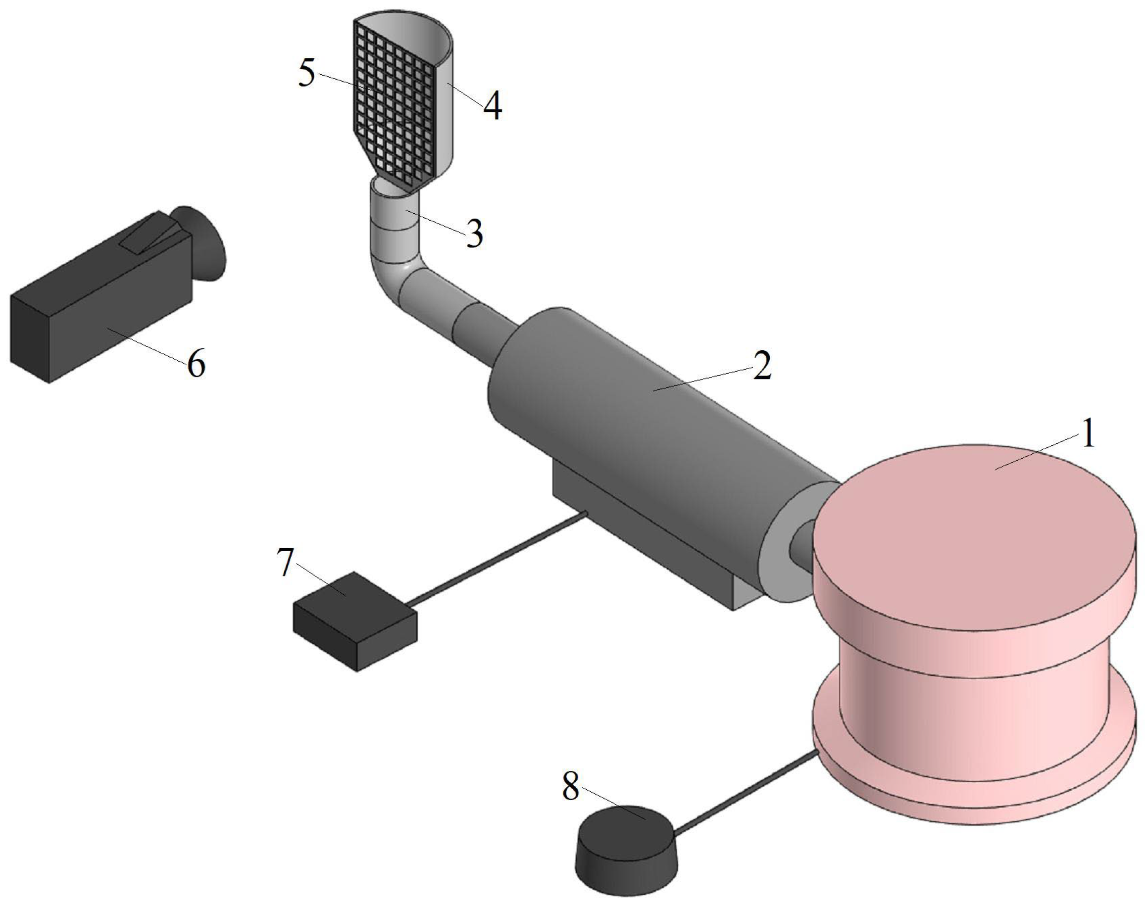
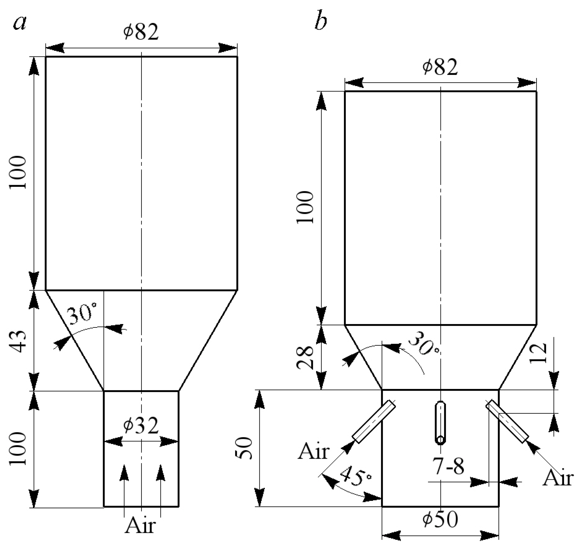
2. Description of the Test Bench, Experimental Methods, and Studied Designs for Supplying Air to a Vertical Diffuser

The flow distribution inside a vertical diffuser when air is supplied with different supply channel designs was studied on the test bench shown in Figure 1. The test bench consisted of a forcing compressor (with the ability to change the air flow q through the system in the range from 0.015 to 0.06 m3/s), a duct air heater (with the ability to control air heating temperature up to 65 ± 1 °C), supply systems of various configurations (the designs are presented below), and a transparent vertical diffuser (geometric dimensions are also given below) with a mesh inside (the mesh cell size was 1 × 1 mm). This mesh served to record the flow structure with thermal imaging. A reservoir with a honeycomb was installed between the compressor and the duct heater to stabilise the flow (not shown in Figure 1).
The experiments were carried out under stationary air flow conditions in the system under consideration for different air flow rates. The Reynolds number Re for the air flow at the outlet of the supply channel ranged from 42,500 to 150,000. The Re calculation was performed for a diffuser configuration with air supplied through a channel with a circular cross-section.
The thermal imaging method used in this study is described in more detail in [34]. This method consists of placing a thermal imaging grid of polymer threads in the flow and is based on the analysis of temperature dispersion fields obtained through a thermal imager. Accordingly, as stated above, it was necessary to preheat the air to a temperature of 65 ± 1 °C to obtain thermograms (temperature dispersion fields). Thus, a qualitative physical picture of the flow structure in a vertical diffuser was obtained using this method. It is necessary to utilise other experimental methods to obtain quantitative characteristics of the flow. When carrying out the experiments, the following equipment provided the measuring base:
-
A thermal imager (model Testo 890-2, Titisee-Neustadt, Germany), with which thermograms of the flow distribution inside the vertical diffuser (measurement error ± 0.2 °C) were obtained (calibration of the device was carried out in a specialised measuring centre);
-
A constant-temperature hot-wire anemometer (model Irvis TA-5.1, Kazan, Russia) through which air flow through the system was determined (the relative standard measurement uncertainty q was 5.1%);
-
Thermocouples for current temperature control in different parts of the system (relative standard measurement uncertainty was 1.5%).
This study studied the following two design methods for supplying air to a vertical diffuser:
(1)
The conventional method for supplying air through a straight channel from below (Figure 2a);
(2)
Nozzle air supply through four tubes at an angle of 45° (Figure 2b).
The main geometric dimensions of the diffuser under study are presented in Figure 2. Figure 2 also shows schematic diagrams of both design methods for supplying air.
This study further examined the influence of the cross-sectional shape of the channel and nozzle tubes on the gas-dynamic flow structure in a vertical diffuser. Stable, longitudinal, and vortex structures arise in square and triangular channels, which have a significant impact on the gas-dynamic behaviour of air flow [35,36].
Consequently, for the traditional air supply method, three cross-sectional shapes were used, namely circle, square, and equilateral triangle, the geometric dimensions of which are shown in Figure 3. The geometric dimensions of the supply channels were determined based on the equality of the equivalent hydraulic diameter for all configurations (circle diameter—32 mm; square side—32 mm; and triangle side—55 mm). Accordingly, the cross-sectional area of the square was 21% larger than the circular cross-section. The area of the triangle was 39.5% larger than the circle. It should be noted that the experiments were performed for the same volume flow through the system for all configurations of the supply channels. The length of the supply channel in all cases was approximately 100 mm. All supply channels had a technically smooth surface (average roughness was 6.3 µm).
Photographs of the supply channels with different cross-sections and vertical diffusers are shown in Figure 4. It should be noted that the visualising grid did not pass through the centre of the triangle (Figure 4c). This is due to the geometric limitations of the vertical diffuser and the dimensions of the triangular cross-section. It can be assumed that the thermograms will show the flow structure in one of the corners of the triangle.
A general view of another method for supplying air to a vertical diffuser with nozzle tubes is shown in Figure 5a. Figure 5b also illustrates the geometric dimensions of nozzle tubes with cross-sections of different shapes.
The geometric dimensions of the nozzle tube cross-sections were also determined based on the equality of the equivalent hydraulic diameter for all configurations (circle diameter—5 mm; square side—5 mm; and triangle side—8.6 mm). The total areas of square and triangular tubes are 21 and 39.5% larger than those for round tubes. The total length of the nozzle tubes in all cases was approximately 100 mm. The length of the tube sections with square and triangular cross-sectional shapes was 60 mm. All nozzle tubes had a technically smooth surface (average roughness was 6.3 μm). It should be noted that the experiments were carried out in modes with the same volumetric air flow through a system with different configurations of supply tubes.
Nozzle tubes (four pieces) were installed symmetrically on a cylindrical base at an angle of 45° relative to the vertical axis. Photographs of air supply nozzles with different tube designs and vertical diffusers are shown in Figure 6.
Therefore, in this research, six air supply designs in a vertical diffuser and their influence on the gas dynamic structure was studied with thermal imaging.
It should be noted that half of the diffuser was manufactured for experimental studies. The use of a half vertical diffuser assumes that the flow in the vertical diffuser is completely symmetrical for a stationary mode of air movement.
This study is aimed at experimentally obtaining a qualitative physical picture of the flow structure in a vertical diffuser for different air supply methods. Quantitative data and more detailed information about the gas dynamics of flows will be obtained using the PIV method in the future.

3. Analysis of the Gas-Dynamic Structure of Flow in a Vertical Diffuser with Different Air Supply Methods

First, experimental data (thermograms) on the flow structure in a vertical diffuser were compared with the results of other authors (Figure 7). This is necessary because half of the diffuser was used to obtain the thermograms in this study.
Thermograms were obtained at a specific time for a stationary flow (output to the mode of about 10 min) in Figure 7 and all subsequent figures. Figure 7 confirms that the thermograms show the main elements of the flow structure in a vertical CD in comparison with the data of other authors. Accordingly, the method of thermal imaging is suitable and reliable for studying the patterns of changes in the gas dynamics of flows in the diffuser for different methods of air supply. At the same time, the use of half a vertical diffuser is acceptable for studying stationary flows.
It has been established that the transverse profiling of the supply channel has significant effects on the flow structure in a CD (Figure 8). Figure 8 shows the flow structure in a vertical diffuser at an air flow rate of q = 0.018 m3/s for channels with different configurations.
Figure 8a demonstrates that the use of a channel with a circular cross-sectional shape leads to the creation of a pronounced central flow (saturated colour on the thermogram) in the vertical diffuser. At the same time, in the corners of the diffuser there is virtually no air flow (white areas on the thermogram), that is, stagnant zones are created. It should be noted that in the upper part of the diffuser, air movement occurs throughout the entire volume.
Figure 8b shows that the use of a channel with a square cross-section causes a significant change in the flow structure compared to a traditional round channel. When using a square channel, there are no stagnant zones in the corners of the diffuser. However, the presence of a pronounced central flow along the diffuser axis (dark orange area on the thermogram) should be noted.
Figure 8c illustrates that the use of a triangular channel to supply air to the diffuser also leads to the formation of stagnant zones in the corners. At the same time, the flow along the height of the diffuser is more uniform (in fact, the colour of the thermogram is uniform) compared to round and square channels.
Such significant changes in the flow structure in a vertical diffuser when using profiled supply channels can be explained by the influence of longitudinal vortex structures in the corners of square and triangular profiles. In this case, these structures contribute to a more uniform distribution of flow throughout the entire volume of the diffuser and prevent the formation of stagnant zones. The use of square and triangular pipelines also has a significant impact in the gas exchange systems of piston engines [38,39].
Figure 9 shows the flow structure in a vertical diffuser for holes with different sides when air flows through the system of q = 0.047 m3/s.
Figure 9a demonstrates that an increase in flow rate (accordingly, the speed of flow) through the system causes a significant reduction in stagnant zones in the corners of the vertical diffuser in the case of air supply through a conventional round channel. At the same time, a pronounced central flow along the diffuser axis is maintained. Figure 9b illustrates that an increase in flow through the system has virtually no effect on the structure of the flow in the diffuser when air is supplied through a square channel; there are no stagnant zones in the diffuser and a central flow can be recorded. Figure 9c shows that an increase in flow characteristics through the system also had virtually no effect on the gas-dynamic structure of the flow in a vertical conical diffuser when air is supplied through a triangular channel, significant stagnant zones can be recorded in the corners of the diffuser, and there is a uniform central flow with complete filling of the volume in the upper part.
The data obtained indicate the stable influence of longitudinal vortex structures in profiled channels, which retain their effect on the distribution of air in a vertical diffuser at various air flow rates (velocities).
Figure 10 demonstrates the flow structure in a vertical diffuser for channels with various configurations at an air flow rate through the system of q = 0.057 m3/s.
Figure 10a illustrates that an additional increase in air flow (velocity) through the system led to a decrease in stagnant zones in the corners of the diffuser. Accordingly, we can conclude that stagnant zones decrease with increasing flow (velocity) through the system under consideration (channel diffuser). Figure 10b shows that an additional increase in flow rate through the square channel did not cause any changes in the air distribution inside the vertical diffuser. Figure 10c demonstrates that an additional increase in flow characteristics through the system did not cause any changes in the flow structure in the diffuser when air was supplied through a triangular channel.
It should be noted that when studying the flow structure with air supply through a triangular channel, the mesh was stretched not through the centre of the triangle but with a significant shift to one of the corners. This is due to limitations in the geometric dimensions of the diffuser and supply channel. Therefore, there are plans to refine the data for this design by using other optical methods (in particular, through a PIV measurement system).
The following presents data on the flow structure in a vertical diffuser with nozzle air supply. For example, Figure 11 illustrates the flow structure in a vertical diffuser for a nozzle air supply through tubes with different cross-sections at a flow rate through the system of q = 0.018 m3/s.
Figure 11a shows that when air is supplied through a nozzle and round tubes, intense air movement can be recorded at the base of the diffuser. At the same time, there are no stagnant zones in the corners of the diffuser. The further distribution of air flow along the height of the diffuser is almost uniform, with some deviation towards the right side.
From Figure 11b it can be seen that with nozzle air supply through square tubes, there is also an intense flow movement at the base of the diffuser, with further uniform distribution of air throughout the entire volume of the diffuser. Thus, it can be concluded that the use of a square nozzle tube did not have a significant effect on flow structure in the vertical conical diffuser.
Figure 11c demonstrates that the use of triangular nozzle tubes causes the most uniform distribution of air throughout the entire volume of the diffuser compared to other nozzle tube configurations. In this case, intense air movement can be seen along the vertical axis over almost the entire height of the diffuser (the shape of this movement resembles a ‘carrot’).
A pronounced central flow in the diffuser is not created when using a nozzle air supply. The jet collapse can be seen at the very beginning of the diffuser (square tubes), in the middle part (round tubes), or in the upper part (triangular tubes).
Figure 12 illustrates the flow structure in a vertical diffuser for nozzle air supply through tubes of different configurations at a flow rate of q = 0.047 m3/s.
Figure 12a shows that an increase in flow rate through the system with a nozzle air supply and round tubes does not lead to a change in the flow structure in the vertical diffuser. There is also intense air movement at the base of the diffuser, which is gradually distributed over the entire volume of the cylindrical part with some displacement to the right side.
Figure 12b demonstrates that an increase in flow characteristics through the system with nozzle air supply and square tubes does not cause changes in the flow structure compared to q = 0.018 m3/s. In this case, there is a small area of intense air movement in the lower part of the diffuser and a nearly uniform distribution of air in the rest of the diffuser volume.
Figure 12c illustrates that an increase in air flow through the triangular nozzle tubes actually led to a central air flow in the vertical diffuser. In this case, the flow structure is the most uniform compared to nozzle tubes with round and square cross-sections.
Based on the presented data, it can be stated that when air is supplied through a nozzle into the diffuser, the influence of transverse profiling of the tubes on the flow structure is not very significant. However, it was previously found that the use of square and triangular tubes increases the intensity of turbulence by up to 30% compared to air supply through round tubes [40]. This can have a positive impact on heat exchange processes in real devices since the higher the intensity of turbulence, the higher the level of heat transfer [41].
Figure 13 shows the flow structure in a vertical diffuser for nozzle air supply through tubes of different configurations at a flow rate of q = 0.057 m3/s.
Figure 13 illustrates that an additional increase in air flow through the system confirms the general patterns of the creation of flow structure in a vertical conical diffuser when air is supplied through nozzle tubes with round, square, and triangular cross-sections.
Thus, the evolution of changes in flow structure in the diffuser with nozzle air supply is shown, as is the influence of cross-sectional shape on the distribution of air flow in the diffuser. By choosing the initial conditions and geometric dimensions of the nozzle tubes, it is possible to control the flow structure in a vertical diffuser. In practical terms, this will allow for the customisation of chemical or technological processes to meet the needs of production.

4. Conclusions

Based on the experimental studies of flow structure in a vertical conical diffuser, the following conclusions can be formulated:
  • An experimental setup was created to study various design methods for supplying air to a vertical diffuser under different initial conditions (flow characteristics).
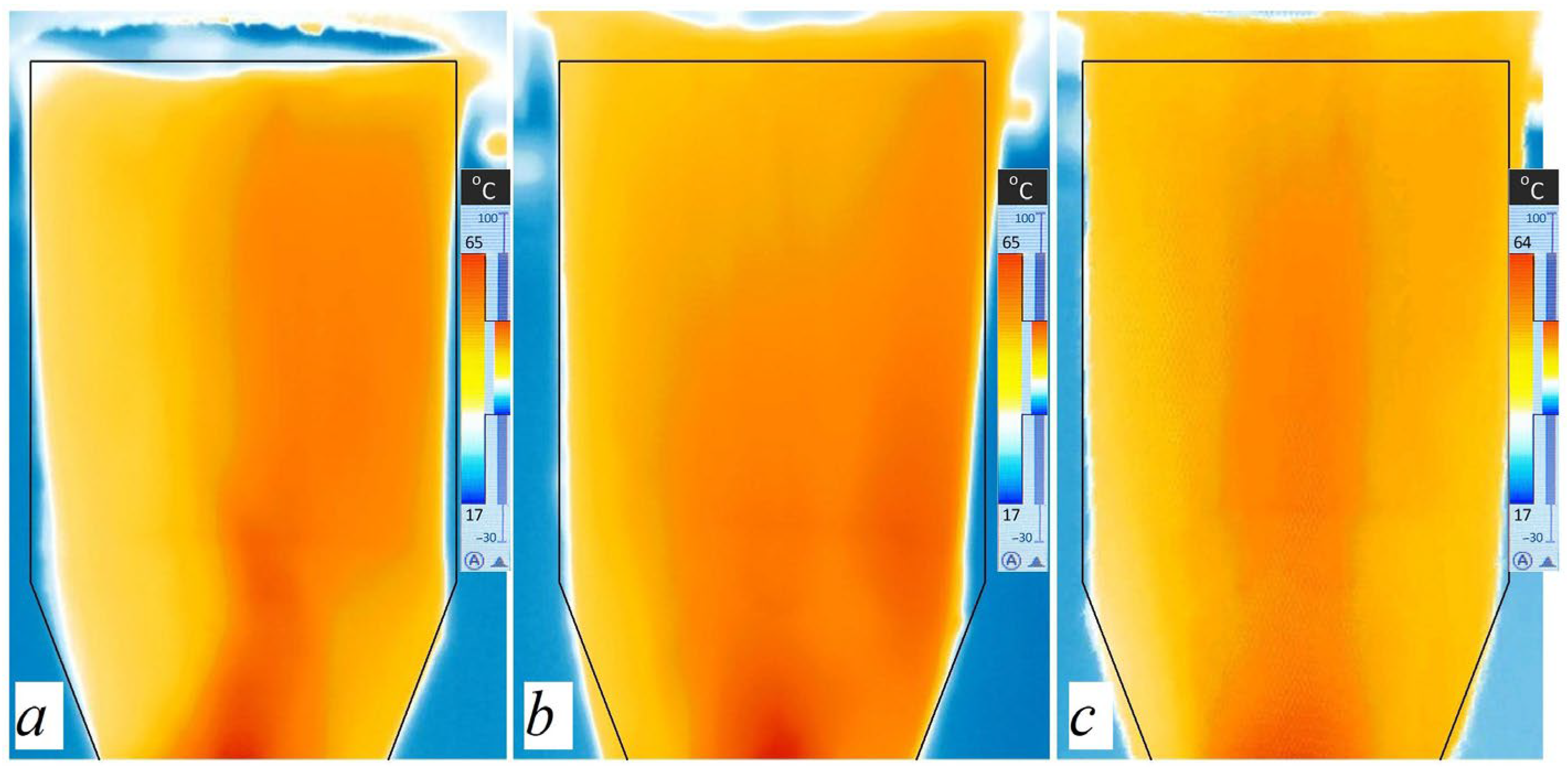
  • Features of the flow structure in a vertical diffuser with a conventional air supply from below through one channel are as follows:
    -
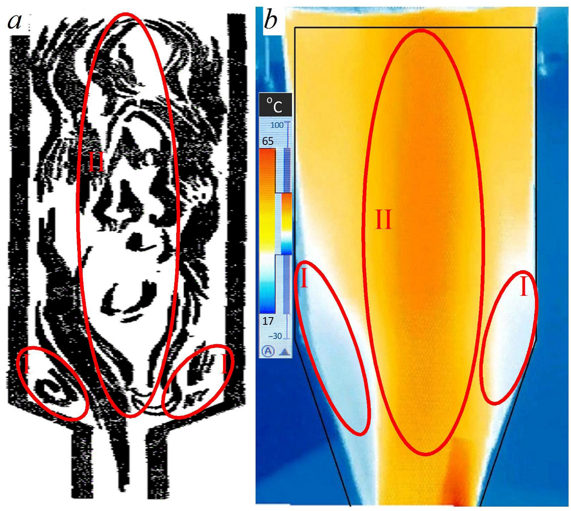
    A pronounced central air flow is created in the diffuser along the vertical axis of the diffuser when using all channel configurations;
    -
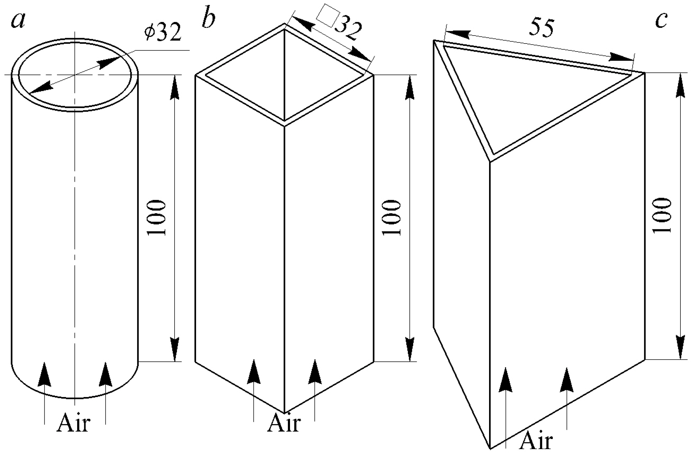
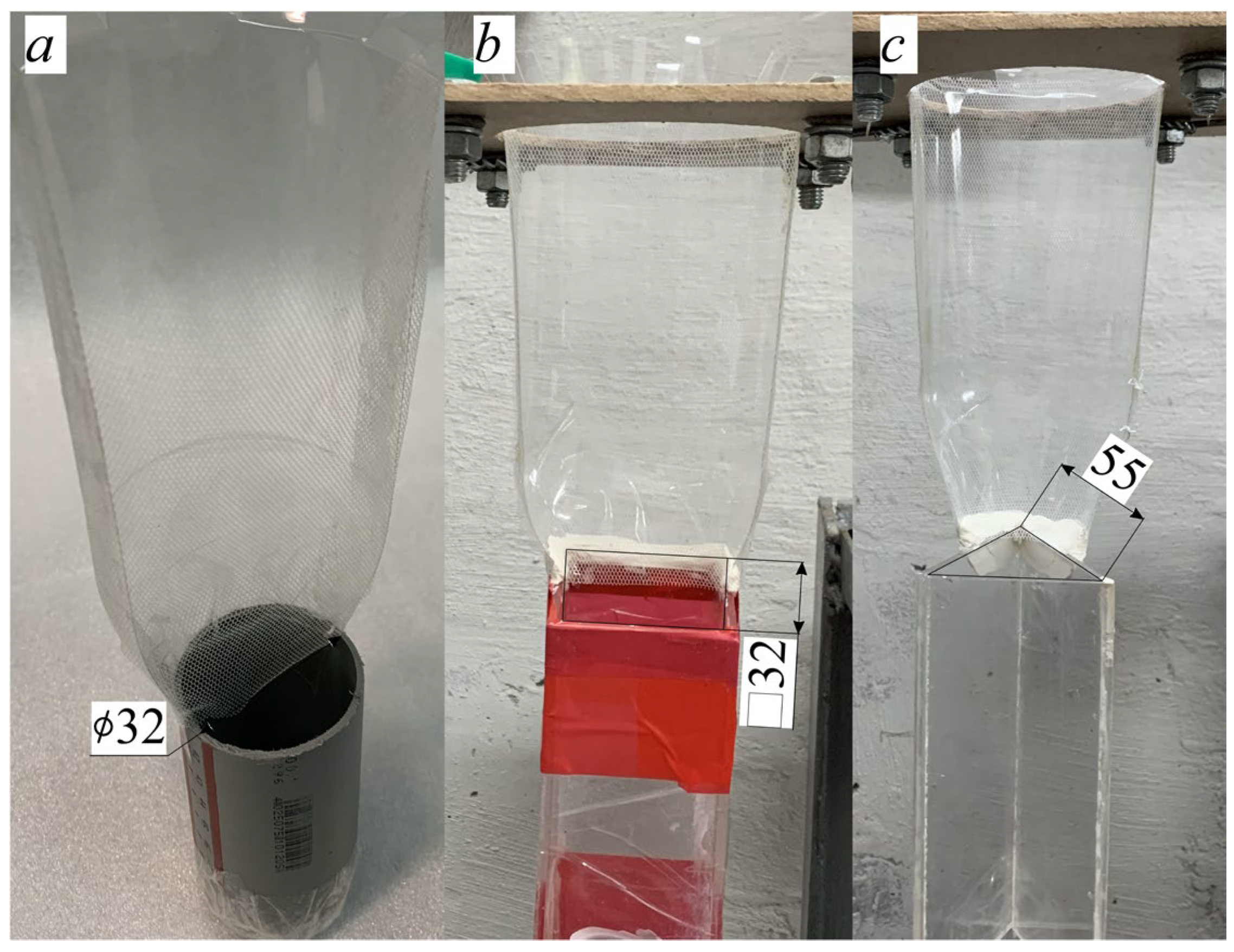
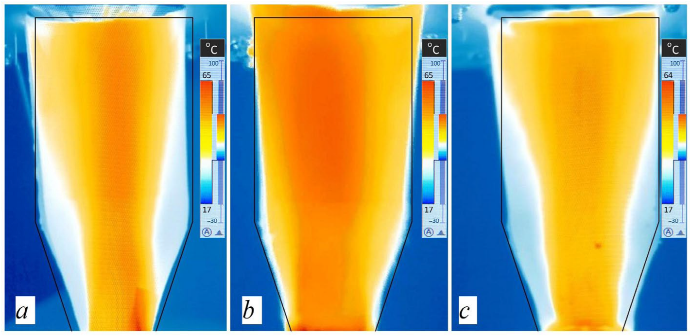
    The shape of the cross-section of the supply channel has a significant impact on flow structure in a CD (round channel—stagnant zones in the corners; square channel—absence of stagnant zones; triangular channel—stagnant zones with a more uniform flow);
    -
    The main patterns of changes in the flow structure are preserved with an increase in air flow through the system from 0.02 to 0.067 m3/s.
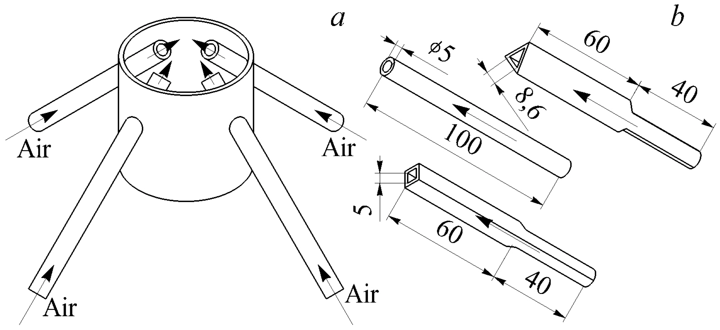
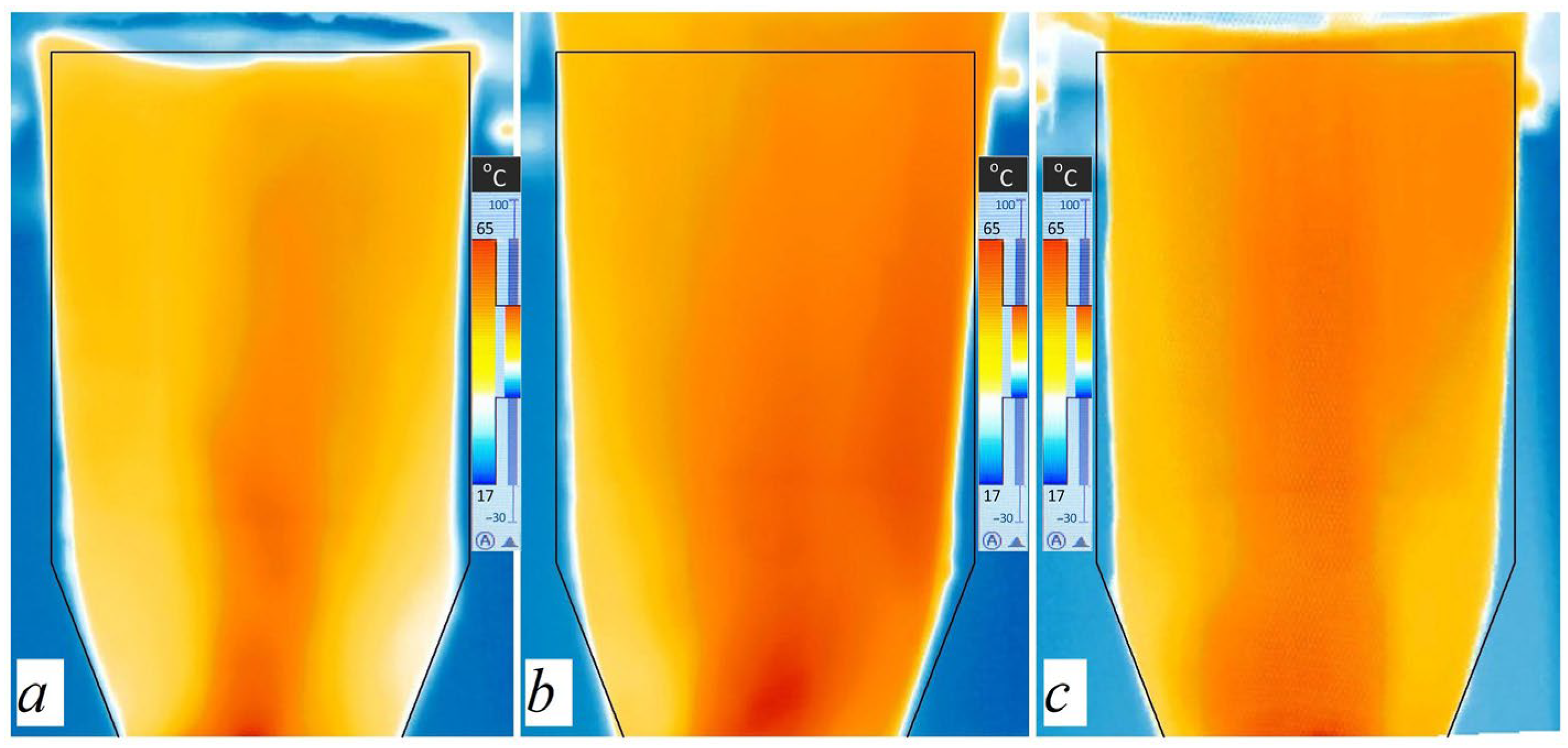
  • Features of the flow structure in a vertical diffuser with nozzle air supply through four tubes at an angle of 45° include the following:
    -
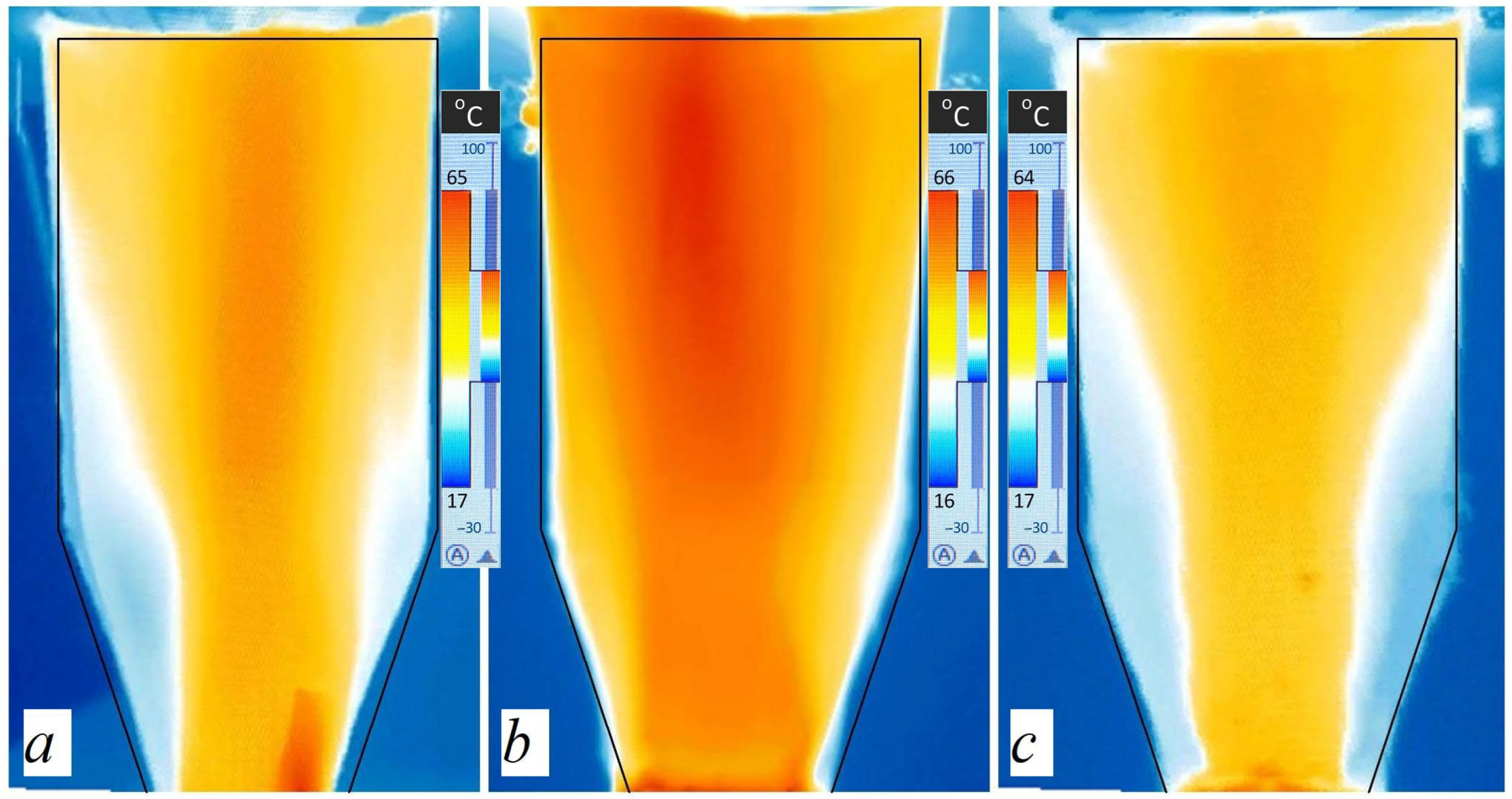
    There are no stagnant zones or central flow in the diffuser;
    -
    The use of square and triangular nozzle tubes leads to a more uniform distribution of air flow throughout the entire volume of the vertical CD;
    -
    An increase in flow characteristics through the system contributes to a more uniform distribution of air flow throughout the entire volume of the diffuser (while the main patterns in the flow structure are preserved).
  • In terms of application, the following recommendations can be formulated:
    -
    The use of conventional air supply through one channel can lead to the creation of stagnant zones in the corners of the diffuser, which is typical of round and triangular cross-sections, and the use of a square supply channel causes a more uniform distribution of air throughout the entire volume of the diffuser;
    -
    Nozzle supply ensures the uniform distribution of air throughout the entire volume of the vertical diffuser with the creation of intense movement in the centre, which is most typical of round and triangular nozzle tubes, and the use of square nozzle tubes causes intense flow movement in the lower part of the diffuser, which quickly collapses upstream, thereby uniformly filling the entire volume of the cylindrical part of the diffuser;
    -
    Conventional air supply through one channel leads to a central flow along the axis of the vertical diffuser with the presence or absence of stagnant zones in the corners of the diffuser, and the nozzle air supply causes uniform distribution of air throughout the entire volume of the diffuser with the creation of an area of intense movement along the vertical axis.
  • According to the authors, the most suitable configurations of air supply to the vertical diffuser are profiled nozzle tubes for the installation for synthesis gas production. In these cases, stagnant zones are not formed in the diffuser, and the main flow has a shape close to the “carrot” (this is the optimal structure for the sawdust floating in the diffuser).
  • Areas for further research are related to obtaining detailed data on the gas dynamics of flow in a vertical diffuser with a hot-wire anemometer and/or PIV system, as well as studying the structure of flow in a two-stage conical diffuser. An additional line of research could be to study the effect of the inclination of the nozzle tubes on the gas dynamics and flow structure in a vertical CD.

Author Contributions

Conceptualisation, L.P.; methodology, L.P. and A.R.; validation, L.P. and A.R.; formal analysis, L.P. and A.R.; investigation, L.P.; resources, L.P.; data curation, L.P.; writing—original draft preparation, L.P. and A.R.; writing—review and editing, L.P.; visualisation, L.P. and A.R.; supervision, L.P.; project administration, L.P. All authors have read and agreed to the published version of the manuscript.

Funding

The research funding from the Ministry of Science and Higher Education of the Russian Federation (Ural Federal University Program of Development within the Priority-2030 Program) is gratefully acknowledged.

Institutional Review Board Statement

Not applicable.

Informed Consent Statement

Not applicable.

Data Availability Statement

The data presented in this study are available on request from the corresponding author. The data are not publicly available due to confidentiality reasons.

Acknowledgments

The authors would like to thank the Ministry of Science and Higher Education of the Russian Federation (Ural Federal University Program of Development within the Priority-2030 Program) for supporting this work.

Conflicts of Interest

The authors declare that this study received funding from the Ministry of Science and Higher Education of the Russian Federation (Ural Federal University Program of Development within the Priority-2030 Program). The funder was not involved in the study design, collection, analysis, interpretation of data, the writing of this article or the decision to submit it for publication.

References

  1. Japikse, D.; Baines, N.C. Diffuser Design Technology; Concepts ETI: Norwich, VT, USA, 1998; 524p. [Google Scholar]
  2. Azad, R.S. Turbulent flow in a conical diffuser: A review. Exp. Therm. Fluid Sci. 1996, 13, 318–337. [Google Scholar] [CrossRef]
  3. Yue, Y.; Shen, Y. CFD-DEM study of spout incoherence phenomena in a conical spouted bed. Powder Technol. 2022, 406, 117529. [Google Scholar] [CrossRef]
  4. Sahu, N.K.; Kumar, M.; Dewan, A. Sophisticated interplay of operating conditions governs flow field transition and optimal conversion inside tangentially fired gasifiers. Energy 2022, 252, 123975. [Google Scholar] [CrossRef]
  5. Wang, K.; Liu, L.; Xu, D.; Gu, H. Simulation and optimization of a conical type swirl-vane separator in nuclear SG. Nucl. Eng. Des. 2023, 408, 112325. [Google Scholar] [CrossRef]
  6. Nazzal, I.T.; Ertunç, Ö. Influence of turbulent flow characteristics on flame behaviour in diffuser combustors. Energy 2019, 170, 652–667. [Google Scholar] [CrossRef]
  7. Masukume, P.-M.; Makaka, G.; Mukumba, P. Optimization of the power output of a bare wind turbine by the use of a plain conical diffuser. Sustainability 2018, 10, 2647. [Google Scholar] [CrossRef]
  8. Mohanan, J.N.; Sundaramoorthy, K.; Sankaran, A. Performance improvement of a low-power wind turbine using conical sections. Energies 2021, 14, 5233. [Google Scholar] [CrossRef]
  9. Zou, A.; Chassaing, J.-C.; Li, W.; Gu, Y.; Sauret, E. Quantified dense gas conical diffuser performance under uncertainties by flow characteristic analysis. Appl. Therm. Eng. 2019, 161, 114158. [Google Scholar] [CrossRef]
  10. Tanasa, C.; Bosioc, A.; Stuparu, A.; Muntean, S.; Susan-Resiga, R. A Perspective Review of Passive Techniques Applied to Control the Swirling Flow Instabilities from the Conical Diffuser of Hydraulic Turbines. Appl. Mech. Rev. 2023, 75, 060801. [Google Scholar] [CrossRef]
  11. Ramesh, B.; Ellappan, S.K.; Nagaraj, S.; Srinivas, G.; Chinthala, S. Modeling and analysis of conical exhaust diffuser. AIP Conf. Proc. 2023, 2492, 040031. [Google Scholar]
  12. Herrera, N.; Galván, S.; Camacho, J.; Solorio, G.; Aguilar, A. Automatic shape optimization of a conical-duct diffuser using a distributed computing algorithm. J. Braz. Soc. Mech. Sci. Eng. 2017, 39, 4367–4378. [Google Scholar] [CrossRef]
  13. Buron, J.-D.; Houde, S.; Deschênes, C. Statistical and spectral analysis of the bulbt conical diffuser flow. Int. J. Fluid Mach. Syst. 2020, 13, 79–89. [Google Scholar] [CrossRef]
  14. Ning, C.; Cao, P.; Gong, X.; Zhu, R. Optimization of Sweep and Blade Lean for Diffuser to Suppress Hub Corner Vortex in Multistage Pump. Machines 2021, 9, 316. [Google Scholar] [CrossRef]
  15. Vaz, J.R.P.; de Lima, A.K.F.; Lins, E.F. Assessment of a Diffuser-Augmented Hydrokinetic Turbine Designed for Harnessing the Flow Energy Downstream of Dams. Sustainability 2023, 15, 7671. [Google Scholar] [CrossRef]
  16. Ferrari, A. Exact solutions for quasi-one-dimensional compressible viscous flows in conical nozzles. J. Fluid Mech. 2021, 915, A1. [Google Scholar] [CrossRef]
  17. Novković, D.M.; Burazer, J.M.; Ćoćić, A.S. Comparison of different CFD software performances in the case of an incompressible air flow through a straight conical diffuser. Therm. Sci. 2017, 21, 863–874. [Google Scholar] [CrossRef]
  18. Teshnizi, E.S.; Momeni, F. Analytical Solutions and Analyses of the Displacement Separating Point in Diffusers. J. Appl. Comput. Mech. 2022, 8, 891–903. [Google Scholar]
  19. Véras, P.; Balarac, G.; Métais, O.; Georges, D.; Bombenger, A.; Ségoufin, C. Reconstruction of numerical inlet boundary conditions using machine learning: Application to the swirling flow inside a conical diffuser. Phys. Fluids 2021, 33, 085132. [Google Scholar] [CrossRef]
  20. Sarukhanyan, A.; Vardanyan, Y.; Vermishyan, G. A study of hydrodynamic viscous fluid flow parameters change regularities in case of a conical diffuser. East.-Eur. J. Enterp. Technol. 2022, 4, 61–71. [Google Scholar] [CrossRef]
  21. Tanasa, C.; Bosioc, A.; Muntean, S.; Susan-Resiga, R. A novel passive method to control the Swirling Flow with Vortex Rope from the conical diffuser of hydraulic turbines with fixed blades. Appl. Sci. 2019, 9, 4910. [Google Scholar] [CrossRef]
  22. Yang, J.; Zhang, Y.; Chen, H.; Fu, S. Flow separation control in a conical diffuser with a Karman-vortex generator. Aerosp. Sci. Technol. 2020, 106, 106076. [Google Scholar] [CrossRef]
  23. Zhou, X.; Wu, H.; Cheng, L.; Huang, Q.; Shi, C. A new draft tube shape optimisation methodology of introducing inclined conical diffuser in hydraulic turbine. Energy 2023, 265, 126374. [Google Scholar] [CrossRef]
  24. Shukri, E.S. Analytical velocity study in a conical diffuser with screw tape inserts. MATEC Web Conf. 2018, 153, 06003. [Google Scholar] [CrossRef]
  25. Shukri Askari, E.S.; Hussein, A.A.; Khudhier, A. Evaluation of velocity distribution utilizing the helically coiled tape in a conical diffuser. IOP Conf. Ser. Mater. Sci. Eng. 2019, 518, 032018. [Google Scholar] [CrossRef]
  26. Mfon, S.A.; Alabi, S.B.; Udoetok, E.S.; Offor, U.; Nsek, E.; Tomas, Z.; Miklík, T. A semi-empirical model for estimation of pressure drop coefficient of a conical diffuser. Chem. Eng. Trans. 2019, 74, 1003–1008. [Google Scholar]
  27. Gosteev, Y.A.; Obukhovskiy, A.D.; Salenko, S.D. On head losses in conical diffusers. AIP Conf. Proc. 2018, 2027, 030048. [Google Scholar]
  28. Tsoy, M.; Skripkin, S.; Litvinov, I. Two spiral vortex breakdowns in confined swirling flow. Phys. Fluids 2023, 35, 061704. [Google Scholar] [CrossRef]
  29. Zhou, X.; Shi, C.; Miyagawa, K.; Wu, H. Effect of modified draft tube with inclined conical diffuser on flow instabilities in Francis turbine. Renew. Energy 2021, 172, 606–617. [Google Scholar] [CrossRef]
  30. Liu, Z.; Favrel, A.; Miyagawa, K. Effect of the conical diffuser angle on the confined swirling flow induced Precessing Vortex Core. Int. J. Heat Fluid Flow 2022, 95, 108968. [Google Scholar] [CrossRef]
  31. Ilić, D.B.; Benišek, M.H.; Čantrak, D.S. Experimental investigations of the turbulent swirl flow in straight conical diffusers with various angles. Therm. Sci. 2017, 21, 725–736. [Google Scholar] [CrossRef]
  32. Hemalatha, A.; Mahalakshmi, N.V. Experimental investigations of flow through wide angle conical diffusers with uniform flow and swirl type velocity distortions at inlet. Therm. Sci. 2018, 22, 2571–2581. [Google Scholar] [CrossRef]
  33. Buron, J.D.; Houde, S.; Deschânes, C. Investigation of the BulbT conical diffuser flow dynamics with TR-PIV and pressure measurements. IOP Conf. Ser. Earth Environ. Sci. 2019, 240, 022037. [Google Scholar] [CrossRef]
  34. Zhilkin, B.P.; Larionov, I.D.; Shuba, A.N. Applications of an infrared imager for determining temperature fields in gas flows. Instrum. Exp. Tech. 2004, 4, 545–546. [Google Scholar] [CrossRef]
  35. Kutateladze, S.S. Fundamentals of the Theory of Heat Transfer; Atomizdat: Moscow, Russia, 1979; 416p. (In Russian) [Google Scholar]
  36. Plotnikov, L.V. Unsteady gas dynamics and local heat transfer of pulsating flows in profiled channels mainly to the intake system of a reciprocating engine. Int. J. Heat Mass Transf. 2022, 195, 123144. [Google Scholar] [CrossRef]
  37. Idelchik, I.E. Aerohydrodynamics of Technological Apparatuses (Supply, Discharge and Flow Distribution along the Section of Apparatuses); Mashinostroenie: Moscow, Russia, 1983; 351p. (In Russian) [Google Scholar]
  38. Plotnikov, L.V.; Zhilkin, B.P.; Brodov, Y.M. The Influence of Piston Internal Combustion Engines Intake and Exhaust Systems Configuration on Local Heat Transfer. Procedia Eng. 2017, 206, 80–85. [Google Scholar] [CrossRef]
  39. Plotnikov, L.V.; Zhilkin, B.P.; Brodov, Y.M. Physical and Numerical Modeling of Thermomechanical Processes in Gas–Air Systems of Piston Engines Under Gasdynamic-Nonstationarity Conditions. J. Eng. Phys. Thermophys. 2020, 93, 594–604. [Google Scholar] [CrossRef]
  40. Plotnikov, L. Mathematical Description of the Aerodynamic Characteristics of Stationary Flows in a Vertical Conical Diffuser When Air Is Supplied through Various Tube Configurations. Axioms 2023, 12, 244. [Google Scholar] [CrossRef]
  41. Terekhov, V.I. Heat Transfer in Highly Turbulent Separated Flows: A Review. Energies 2021, 14, 1005. [Google Scholar] [CrossRef]
Figure 1. Three-dimensional model of a test bench for studying flow structure in a vertical diffuser: 1—compressor; 2—channel heater; 3—supply channel; 4—vertical diffuser; 5—mesh; 6—thermal imager; 7—heating-level control unit; 8—air-flow control unit (note: the three-dimensional solid-state model was created using Russian KOMPAS-3D (v.18) software).
Applsci 13 12141 g001
Figure 2. Geometric dimensions of the vertical diffuser under research and air supply methods: (a) conventional air supply from below through a channel; (b) nozzle air supply at an angle.
Applsci 13 12141 g002
Figure 3. Sketches of the designs of supply channels with different cross-sectional shapes: (a) circle; (b) square; (c) triangle.
Applsci 13 12141 g003
Figure 4. Photographs of the studied vertical diffuser structures with different cross-sectional shapes of the supply channel: (a) circle; (b) square; (c) triangle.
Applsci 13 12141 g004
Figure 5. Overall view of the design for nozzle air supply into a vertical diffuser (a) and geometric dimensions of supply tubes with different cross-sectional shapes (b).
Applsci 13 12141 g005
Figure 6. Photographs of the studied structures of a vertical diffuser with a nozzle air supply through tubes with different cross-sections: (a) circle; (b) square; (c) triangle.
Applsci 13 12141 g006
Figure 7. Comparison of the flow structure in a vertical diffuser for Re ≈ 40,000: (a) data [37]; (b) the author’s thermogram. Note: I—stagnant zone; II—core of the flow.
Applsci 13 12141 g007
Figure 8. Thermograms of the flow structure in a vertical diffuser when air is supplied through channels with different cross-sectional shapes (flow through the system q = 0.018 m3/s): (a) circle; (b) square; (c)—triangle.
Applsci 13 12141 g008
Figure 9. Thermograms of the flow structure in a vertical diffuser when air is supplied through channels with different cross-sectional shapes (flow rate through the system q = 0.047 m3/s): (a) circle; (b) square; (c) triangle.
Applsci 13 12141 g009
Figure 10. Thermograms of the flow structure in a vertical diffuser when air is supplied through channels with different cross-sectional shapes (flow rate through the system q = 0.057 m3/s): (a) circle; (b) square; (c) triangle.
Applsci 13 12141 g010
Figure 11. Thermograms of the flow structure in a vertical diffuser with nozzle air supply through tubes with different cross-sectional shapes (flow through the system q = 0.018 m3/s): (a) round; (b) square; (c) triangular.
Applsci 13 12141 g011
Figure 12. Thermograms of the flow structure in a vertical diffuser with nozzle air supply through tubes with different cross-sectional shapes (flow rate through the system q = 0.047 m3/s): (a) circle; (b) square; (c) triangle.
Applsci 13 12141 g012
Figure 13. Thermograms of the flow structure in a vertical diffuser with nozzle air supply through tubes with different cross-sectional shapes (flow rate through the system q = 0.057 m3/s): (a) circle; (b) square; (c) triangle.
Applsci 13 12141 g013
Disclaimer/Publisher’s Note: The statements, opinions and data contained in all publications are solely those of the individual author(s) and contributor(s) and not of MDPI and/or the editor(s). MDPI and/or the editor(s) disclaim responsibility for any injury to people or property resulting from any ideas, methods, instructions or products referred to in the content.

