Abstract
Dental CBCT and panoramic imaging play a pivotal role in dental diagnosis and treatment planning, alongside the indispensable use of computed tomography (CT) and X-ray imaging in dentistry, particularly for surgical planning. Given the widespread adoption of dental cone beam CT in clinics today, we explore a novel approach in this study—utilizing CT’s three-dimensional (3D) data to reconstruct a two-dimensional (2D) panoramic dental image. This method eliminates the requirement for an extra panoramic scan. In this work, we propose a novel framework to generate an enhanced and extended 2D panoramic view by using the dental arch extracted from 3D CBCT. Our method involves segmenting the patient’s dental arch from their 3D CBCT image by identifying horizontal slices with above-average intensity, followed by morphological operations, including dilation, Gaussian filtering, and skeletonization, to delineate the dental arch line. Additionally, we extend the dental arch beyond the wisdom teeth using quadratic curve fitting. Finally, we employ Maximum Intensity Projection on rotated cubic segments aligned with the dental arch curve to produce captivating panoramic images. The panoramic view produced using our proposed method, when compared to the results obtained from BlueSky and OpenInventor, exhibited superior enhancements and greater accuracy in panoramic visualization.
1. Introduction
In the field of dentistry, various advanced digital technologies, including optical imaging, X-ray imaging, and 3D printing, are utilized for medical image diagnostics and healthcare purposes [1]. In particular, the dental cone beam computed tomography (CBCT) and panoramic imaging are commonly used for diagnosis and treatment planning [2,3]. However, panoramic images generated from dental CBCT data may encounter certain challenges. These challenges encompass issues such as low contrast, irregular unwrapping, and a shortened panoramic view. The challenges stem from the presence of non-relevant tissue and metallic implants within the patient’s jaw section. Such objects within the CBCT data significantly affect the accuracy of diagnostic results [4]. Panoramic radiography is crucial for diagnosing dental issues and planning treatment by offering detailed information. However, excessive exposure to CT radiation increases the cancer risk in patients [5]. Therefore, an algorithmic approach to extract a panoramic view from CBCT data is needed to minimize repeated radiation exposure for patients [6]. Despite the availability of CBCT’s 3D anatomical information, panoramic dental view remains in demand for its ability to display anatomical structures in a single plane with a wide field of view [7]. This need for panoramic imaging persists in clinical settings even after CBCT acquisition. DICOM files collected from patients typically include 2D slices of their CT data. Dental CBCT visualization is commonly achieved through dynamic volume rendering and multiplanar reconstruction (MPR) slices [8]. Nevertheless, the persistent need for a panoramic view persists, driven by the presence of intricate anatomical structures within a single field of view. These structures are of paramount importance for surgical planning.
Two methods are available for capturing comprehensive panoramic images: a hardware-based approach and a software-driven approach. The hardware approach involves the CBCT scanner’s rotating shaft following a predefined trajectory [9]. However, fixed scan trajectories can result in out-of-focus panoramic images when the patient’s dentition significantly deviates from the focal plane, and additional radiation exposure occurs during an extra panoramic scan [10]. In contrast, software approaches create panoramic images from dental CBCT data by extracting image slices at uniform dental arch angles [11]. This process typically involves two steps: first, extracting the dental arch that represents the teeth and jawbone, and second, extracting the maximum intensity projection from the volumetric CT data near the dental arch coordinates and incorporating it into a panoramic image view. This approach allows panoramic image acquisition without requiring hardware modifications to existing dental CBCT equipment [12]. Unlike panoramic scan systems, software-based methods do not suffer from out-of-focus issues because they extract the panoramic image along the dental arch. However, the quality of these methods depends on the CBCT image’s quality and the accuracy of the dental arch. Various algorithms have been developed to automatically extract precise dental arches, but their accuracy diminishes in the presence of missing teeth and metal artifacts in the CBCT image [13]. Severe metal artifacts can persist in the panoramic image despite setting an ideal dental arch, ultimately reducing the panoramic image’s quality [14]. In their work [14], the authors employed a binary thresholding technique followed by morphological operations on the teeth slice section to accurately extract the dental arch curve from the CBCT data. While these methods effectively address the issue of missing teeth sections, they have the limitation of a shortened panoramic view, which not only misses the wisdom teeth but also the TMJ bones in their panoramic view. The TMJ region is crucial for the disease diagnostic procedure from the dental panoramic image of the patient.
Over the past decades, several methods have been developed to generate 2D panoramic images from CT datasets [15]. Some techniques involve the manual definition of dental arch coordinates followed by Maximum Intensity Projection (MIP) over specified angles [16]. Other methods involve automatic segmentation to separate the maxilla and mandible regions, followed by spline-based reconstruction [3]. The accuracy of the dental arch has a crucial impact on the development of panoramic view from the CBCT data [17]. In [3], the author generates separate panoramic views of the upper and lower jaw and subsequently employs a hierarchical multi-step deep learning model for tooth segmentation in 3D CBCT data. In [13], the method determines the occlusal plane, generates intersection points between the teeth and an offset plane from the occlusal plane in CBCT images, and ultimately determines the dental arch form by fitting a curve to the intersection points using cubic B-spline curve approximation. The author in [18] generates a panoramic view by segmenting the bone and teeth and then detects the internal mandible curve in the segmented image, which is used to generate the panoramic image. The method is fast but results in shortened and less precise unwrapping results. The author in [19] uses teeth pulps and the entire mandible to generate a panoramic image by employing thresholding and morphological operations over the dental arches. The panoramic view generated by BlueSkyPlan software (V4.11) shows a shortened view, which skips the TMJ section [20]. These techniques have made substantial contributions to the field, providing both manual and automated methods for reconstructing panoramic images from CT data [21]. Nonetheless, each method is susceptible to various noise and artifacts caused by the presence of metallic structures and non-uniform teeth orientations [22]. The unwanted branching structure of the dental arch, resulting from these techniques, contributes to inaccuracies in panoramic image generation. Furthermore, these methods produce limited-length arches that omit the TMJ bones from the panoramic view [23]. The shortened, less enhanced, non-linear unwrapped dental panoramic view severely impacts medical image diagnostics and planning procedures.
To address the limitations associated with existing software approaches, this research article introduces a novel method for panoramic image generation that leverages CBCT projection data. Given that CBCT scans offer projection data encompassing the full angular range, it is theoretically feasible to selectively extract and reconstruct panoramic projection data from these CBCT projections. In practice, an offset detector geometry is commonly employed to cover a wider field of view (FOV) in dental CBCT, with the flat-panel detector center being horizontally aligned with the system’s principal X-ray. The process of extracting panoramic projection data from CBCT projection data begins by isolating an appropriate dental arch from a CBCT image, determined by slice positions where the moving average intensity exceeds a specific threshold. Subsequently, a top-view image obtained via MIP from the chosen DCM slices undergoes preprocessing involving various morphological and filtering operations to obtain the raw dental arch line. A curve fitting operation is then applied to extend the dental arch and incorporate the temporomandibular joint (TMJ) section into the panoramic image. Finally, the perpendicular angle across each dental arch point is used to rotate and extract the MIP panoramic slice at each position for the small cubic CBCT segment. In comparison to conventional software approaches that rely on dental CBCT images instead of projection data, the proposed method offers advantages, as it is not contingent on the quality of the CBCT image; rather, it directly reconstructs the panoramic image from the extracted projection data.
The main contribution of this work is listed below:
- Dental Arch Detection: The proposed method detects a highly accurate dental arch from the existing dental teen slices only. Teeth localization is achieved by thresholding the moving average intensity values extracted from the front view MIP image. Further enhancement of the dental arch is accomplished through a series of morphological operations, including dilation, filtering, and skeleton detection methods.
- Dental Arch Approximation and Extension: The proposed framework employs the quadratic kernel-based curve fitting to generate a mathematical expression that best fits the dental arch. The extension of the dental arch up to the TMJ locations is then obtained through that quadratic expression.
- Localized Maximum Intensity Project Stitching: Trajectory-based cubic segments are extracted and rotated to an angle perpendicular to the dental arch at that specific coordinate point. The localized MIP obtained from each rotated cubic segment is then cropped and stitched together to obtain the panoramic view of the given CBCT data.
- Contrast Enhancement Operation: The low-contrast raw panoramic image obtained through the proposed framework shows fewer details of the gums, teeth, and TMJ section. It is further enhanced by the post-processing contrast normalization procedure to display a more detailed panoramic image at the output.
The rest of the paper is structured as follows: Section 2 outlines the methodology of the proposed model, offering detailed explanations of each step supported by mathematical models. In Section 3, we analyze the experimental findings and compare them to state-of-the-art models. Lastly, Section 4 wraps up the paper, delving into potential avenues for future research.
2. Proposed Methodology
The proposed framework, as depicted in Figure 1, is designed to convert the input 3D CBCT data into a 2D panoramic image. This framework comprises five key stages: Teeth localization, Dental Arch Detection, Dental Arch Fitting and Extension, MIP Stitching, and Enhancement. The final panoramic image generated using this method not only reveals the dental structures but also provides visualization of the TMJ, empowering medical professionals with comprehensive information for medical investigation and diagnosis. Each stage of the dental panoramic image generation process is discussed in detail below.
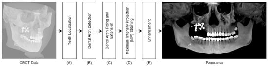
Figure 1.
DeAPIR Framework: Transforming 3D CBCT into 2D Dental Panoramic Image—(A) Teeth Localization (B) Arch Detection (C) Arch Extension (D) MIP Generation and Stitching (E) Image Enhancement.
2.1. Teeth Localization
The section on teeth localization plays a critical role in achieving accurate dental arch estimation and detection. Inaccurate CBCT slices can result in the generation of a false dental arch, ultimately leading to an incorrect panoramic image at the final stage. To address this issue, a meticulous process is employed to identify the dental teeth slices within the input CBCT. This process utilizes a horizontal moving average threshold applied to the MIP view of the CBCT. The complete dental slice detection procedure is illustrated in Figure 2. The MIP is derived from the CBCT data by considering only the maximum intensity value at each position, as defined by the following equation.
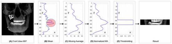
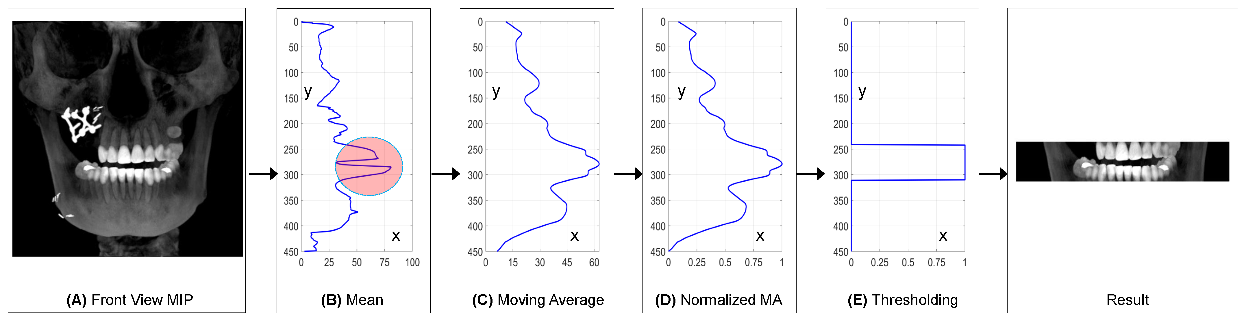
Figure 2.
Teeth localization in CBCT 3D array: (A) CBCT front view MIP generation (B) Mean MIP along Y-axis (C) Moving average of mean vector (D) Normalization of moving average vector (E) Threshold applied to normalized moving average vector.
In Equation (1), represents the front MIP image derived from the input CBCT volume, denoted as . The coordinates x, y, and z are defined within the context of , where the index z varies from 1 to K in the input CBCT. Figure 2A illustrates the distribution of concerning each location defined by x and y. In Equation (2), corresponds to the mean values obtained from the MIP with respect to each index y. Figure 2B provides a visual representation of the values as a function of y. Equation (3) introduces , which represents the moving average of the mean values obtained from Equation (2). The symbol w denotes the window size used for the moving average procedure. Figure 2C displays the values in relation to the index n. Additionally, represents the normalized moving average vector . Figure 2D illustrates the values as a function of n. Figure 2E provides insight into the values, where equals 1 for those CBCT slices containing the dental teeth section as given in Figure 2. Subsequently, the teeth section undergoes further analysis for dental arch detection.
2.2. Dental Arch Detection
The dental arch detection procedure undergoes several morphological operations. The teeth section of the CBCT is utilized in the dental arch detection procedure. The MIP image of the teeth section is binaries, filtered and skeletonized to obtain the dental arch line. The dental arch is derived through the following equations.
where is the binary image obtained from the MIP () and ⊖ denotes the erosion operation while ⊕ denotes the dilation operation. SE represents the structural element, which is a 5 × 5 matrix of ones.
where represents the erosion operation applied k times to while the symbol ⋃ combines the results of erosion at different levels of iteration, effectively building the skeleton. Through the morphological skeleton operation, the obtained dental arch line includes unwanted noises, visible in Figure 3.
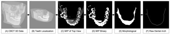
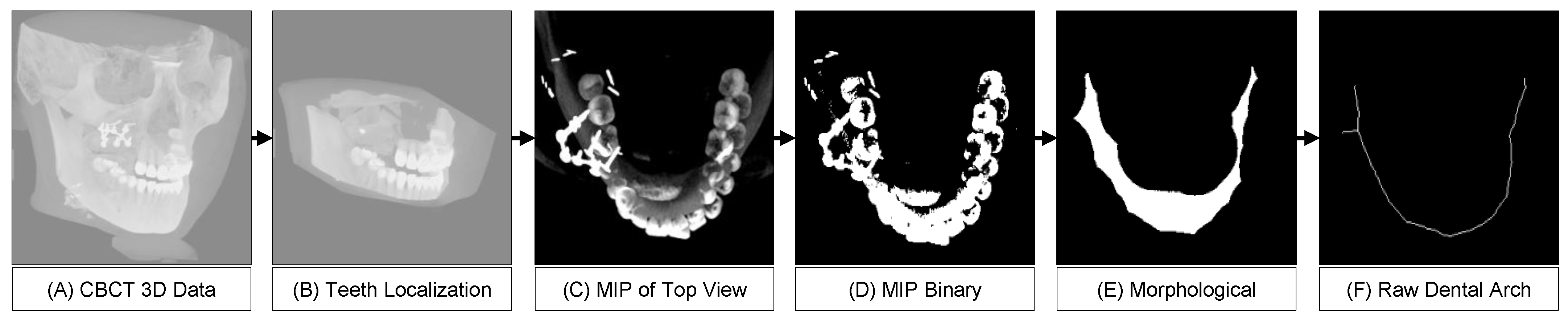
Figure 3.
Dental arch detection: (A) 3D CBCT scan, (B) Cropping teeth section, (C) Top view MIP, (D) Binary conversion, (E) Morphological operations, (F) Final dental arch.
2.3. Dental Arch Post-Processing
The dental arch generated during the dental arch detection process contains a little undesired branch that is shown with a circle annotation in Figure 4a. This branch affects the panoramic image re-construction procedure and is therefore filtered from the raw dental arch through a post-process procedure. The post-processing includes an initial Gaussian filtering process, which results in a blurred image. The blurred image is generated with the following expression:
where the in Equation (12) denotes the binary threshold for the dental arch, and the variable stores the dental arch after the post-processing operation. The variable stores the coordinates of the dental arch. The dental arch plotted on the teeth MIP image in the Figure 4e shows the accuracy of the detected arch curve. The notation in Equation (14) defines a set of x and z coordinates where is equal to value 1. The location coordinates define all (x, z) pairs through which the dental arch passes. The detected dental arch connects the wisdom teeth following the trajectory of the teeth; however, the panoramic image requires the the visibility up to the TMJ joints. Therefore, the detected dental arch fitting to the quadratic curve is performed for dental arch extension.
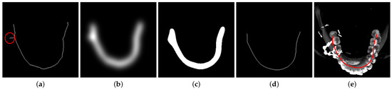
Figure 4.
Post-processing of the raw dental arch to smooth and remove branch structures: (a) Raw dental arch curve, (b) Gaussian filter output, (c) Result after binary thresholding, (d) Morphological skeletonization on the binary image, (e) Detected dental arch annotated on the top-view MIP dental image.
2.4. Dental Arch Fitting and Extension
The dental arch curve is fit to a quadratic curve where the extension is performed by deploying the extended array x, The extended quadratic curve-fitted data are shown in the Figure 5b. The coordinates of the dental arch obtained for fitting and extension are represented with (, ).
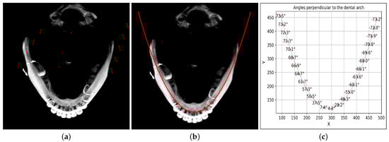
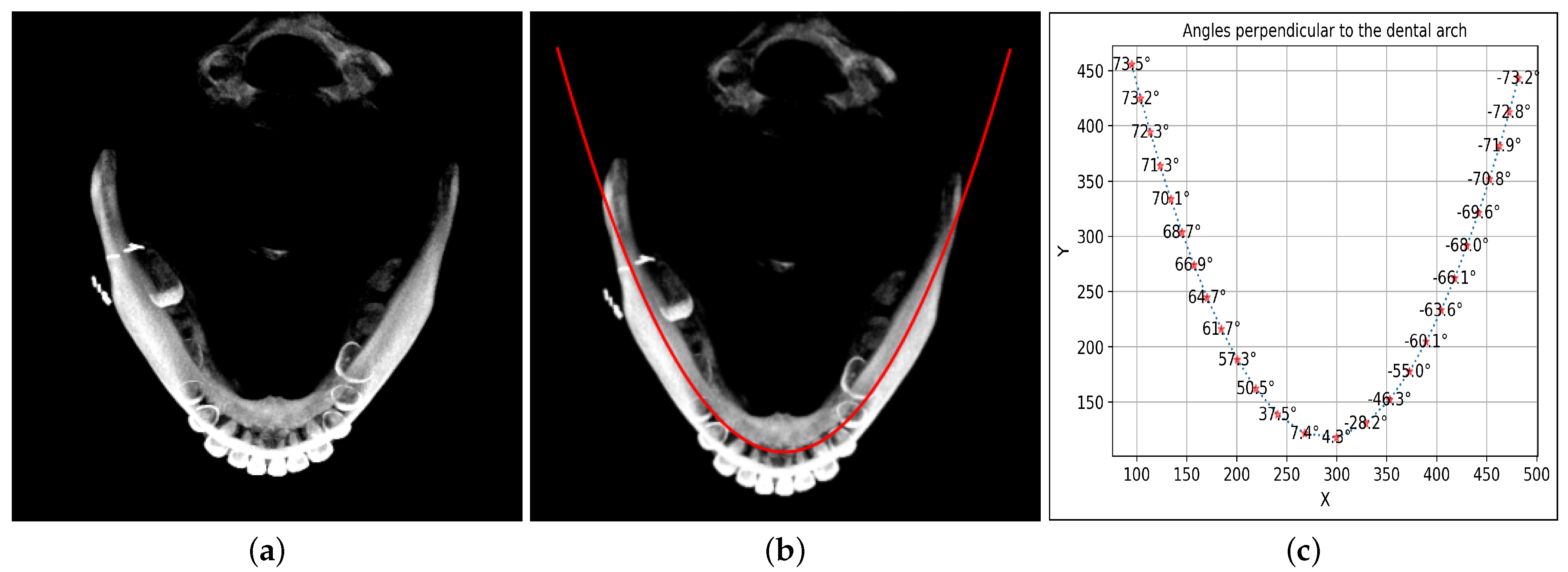
Figure 5.
Quadratic fitting of dental arch extending beyond wisdom teeth, with perpendicular angle calculations: (a) Top view MIP image, (b) Dental arch approximation using quadratic expression and extension, (c) Calculation of perpendicular angles at each extended dental arch point.
2.5. MIP Stitching
To generate the panoramic image, initially, the perpendicular angle to the curve (, ) is identified as given in Figure 5c. The perpendicular angles are calculated through the following equation:
In Equation (15), denotes the ith perpendicular angle obtained from the dental arch coordinate point (, ). In Equation (16), represents the ith CBCT cube corresponding to the dental arch coordinate point (, ) with width . In Equation (17), is the rotation matrix. In Equation (19), represents the ith MIP strip obtained from each CBCT cube segment centered at the coordinate point (, ). In Equation (20), is the panoramic image obtained after stitching or combining all the together.
2.6. Enhancement
The panoramic view obtained by stitching the MIP of localized CBCT cubes centered at dental arch coordinates resulted in a dark, low-contrast image that shows minor details for the patient’s dental treatment and surgical planning. The panoramic image requires contrast enhancement to increase the difference in the image’s low and high intensities. Therefore, contrast normalization is applied to obtain the enhanced version of the same image as shown in first Figure in Section 3. The following mathematical operation is applied for contrast enhancement of the panoramic view.
In Equation (21), represents the enhanced panoramic image obtained after contrast normalization. is the panoramic image, with and denoting the highest and lowest intensity values present in the image , respectively.
3. Results
The research article evaluated the proposed DeAPIR framework on a computer with the following specifications: an Intel(R) Xeon(R) CPU E5-2630 v4 processor running at 2.20 GHz (with two processors), 48 GB of RAM, and Windows 10 as the operating system. Python 3.11 was used for implementing the method. The average time required to obtain panoramic projection data was 48 s. The results obtained using the proposed method were compared to panoramic images generated with Blue Sky and OpenInventor. The CBCT data of fifteen patients have been utilized as part of the standard for developing an orthodontic treatment plan. The CBCT data, consisting of DICOM files with dimensions of 551 × 450 × 551, were collected through 3D scanning devices and used in the research for the development of the proposed surgical planning software.
In the experiment, the input CBCT had dimensions of 559 × 450 × 559, comprising 559 values in the x-direction, 450 in the y-direction, and 559 in the z-direction. A 2D MIP was derived from the CBCT in the xy-plane with dimensions of 559 × 450. The primary dental component, representing the teeth section, was localized using the proposed moving average thresholding method, as depicted in Figure 2. The mean values were initially determined by averaging all pixel intensities along the x-axis corresponding to each y-axis value. This process resulted in a vector that formed a graphical shape with higher values in the bright pixel region along the y-axis. The dimension of the mean vector was thus 450 values along the y-axis, as shown in Figure 2B. The space between the maxilla and mandible in the MIP image created a concave structure in the mean vector, which was annotated with a circle in Figure 2B. This concave structure affected the localization of dental teeth, introducing space between maxilla and mandible slices. To address this issue, a moving average vector was generated with a window size of 30, as depicted in Figure 2C. The moving average vector covered the concave section of the vector and produced a global maximum at the dental teeth position within the vector. Although the moving average results were suitable for teeth localization, determining the threshold value was challenging due to the non-uniform dimensions of the MIP. To address this non-uniformity, the moving average was normalized to a range of 0 to 1, and a threshold value of 0.7 was used to create a unit step vector with an amplitude of 1, representing the set of CBCT slices where the dental teeth section existed.
After identifying the dental teeth slices within the CBCT 3D data, we cropped and utilized the desired slices for detecting the dental arch position, as illustrated in Figure 3B. These dental teeth section slices were then processed to generate MIP top views, showcasing the -plane. These MIP top views reveal the arrangement of teeth while excluding any interference from the skull or other bone structures. Subsequently, we binarized the MIP top view and applied morphological operations to identify the dental arch line. However, due to noise and impairments, the raw dental arch may contain undesired branches, as indicated in Figure 4a with a red circle annotation. To obtain a clean arch curve, we applied a 2D Gaussian filter with a filter size of 23 × 23 and a standard deviation of 2 to remove these unwanted branch structures. The binarized results from the Gaussian filter were then subjected to a skeleton detection process to detect the clean dental arch shown in Figure 4d.
The dental arch is then approximated as a quadratic curve to achieve a smooth and extended dental arch shape. Using the quadratic equation, we extend the dental arch line up to the TMJ joints. We calculate and illustrate the perpendicular angles at each point along the dental arch line in Figure 5c. For each point, we use the calculated perpendicular angle to rotate a cuboid centered at the dental arch point. In the xz-plane, each cuboid has a size of 120 × 120 and extends to the full height in the y-direction. The cuboid is rotated around the y-axis based on the perpendicular angle specific to each dental arch point. These rotated cuboids generate the MIP in the xy-plane, with the center region cropped, as demonstrated in Figure 6a. We stitch together the MIPs associated with all dental arch points to create the panoramic image presented in Figure 6b. To enhance the raw panoramic image, we apply an intensity normalization approach, resulting in the final panoramic image. The final panoramic image, as depicted in Figure 6c, provides a comprehensive view, extending from the TMJ joints to the teeth section.
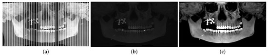
Figure 6.
Reconstruction of Panoramic view from CBCT through dental arch curve coordinates: (a) MIP strips for arch points, (b) stitched MIP strips matching arch points, (c) and enhanced panoramic contrast.
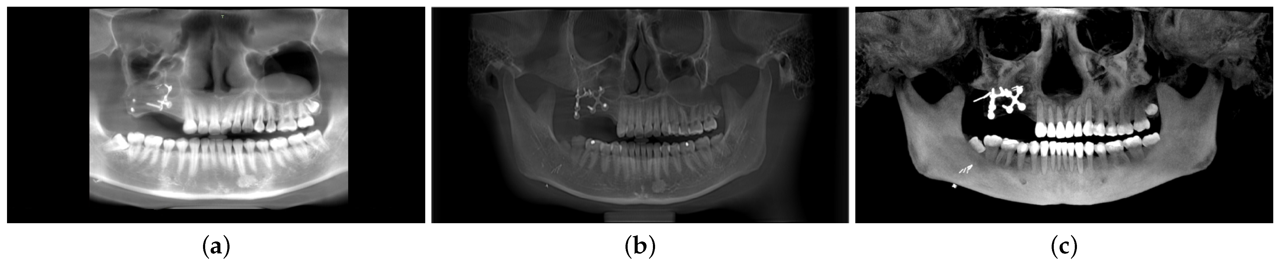
In Figure 7, we present a comparison of our proposed model with two state-of-the-art systems, BlueSky and OpenInventor. The BlueSky results display an incomplete panoramic image, with the TMJ section missing. On the other hand, the OpenInventor result presents a full panoramic image, but the dental teeth contour is not clearly visible. In contrast, our proposed method excels in reconstructing the panoramic view with enhanced details. The proposed model reveals a clear contour for each tooth, enabling a distinct differentiation between the teeth’s root and crown sections. Additionally, our proposed method exhibits significantly reduced computation time compared to OpenInventor. Specifically, OpenInventor requires a total of 634 s for processing a CBCT scan with dimensions of 559 × 450 × 559. In contrast, our proposed model achieves the same task in just 64 s, which is approximately 10 times faster than OpenInventor.
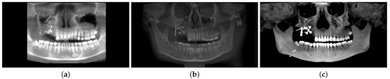
Figure 7.
Performance comparison: DeAPIR vs. state-of-the-art software (a) BlueSkyPlan, (b) OpenInventor, (c) DeAPIR.
The panorama reconstruction methods that exist in the literature have been summarized in Table 1 in terms of the presence of arch detection, fitting operations, morphological operations, intensity projection types, and the enhancement methods. Table 2 compares and summarizes the pros and cons of these methods in comparison to the proposed method to demonstrate the superiority of the proposed approach.

Table 1.
Comparison of proposed methodology with the literature works.
Table 2.
Comparison with the literature in terms of pros and cons.
4. Conclusions
In this article, we address critical issues in surgical planning procedures in dentistry, including frequent patient exposure to radiation, low contrast, and misaligned view angles. We propose a novel method for generating panoramic images from CBCT data. Existing approaches often encounter challenges related to contrast and accuracy in dental arch alignment, especially in the presence of metal artifacts. Our innovative solution utilizes teeth localization, morphological processing, and quadratic approximation to enhance the precision of dental arch extraction, while also incorporating TMJ bones into the panoramic view. Through maximum intensity projections and contrast normalization, we significantly improve image quality. Comparative results with state-of-the-art systems highlight the superiority of our method, offering clearer tooth contours, faster processing times, and a more comprehensive panoramic view. This research lays the foundation for improved diagnostic and treatment planning tools in dental care.
Author Contributions
All authors contributed to the study conception and design. F.: investigation, methodology, validation, visualization, write-up, formal analysis, validation, writing review & editing; S.-Y.M.: conceptualization, writing review & editing, supervision, project administration, funding acquisition. All authors have read and agreed to the published version of the manuscript.
Funding
This research was funded by Chosun University, 2023.
Data Availability Statement
The dataset produced and examined during this research cannot be accessed publicly because of licensing restrictions specific to this study. However, they can be obtained from the corresponding author upon reasonable request.
Conflicts of Interest
The authors declare no conflict of interest.
Abbreviations
| DeAPIR | Dental Arch-Guided Panoramic Image Reconstruction |
| CBCT | Cone Beam Tomography |
| FOV | Field of View |
| MIP | Maximum Intensity Projection |
| TMJ | Temporomandibular Joint |
| MPR | Multiplanar Reconstruction |
| DICOM | Digital Imaging and Communications in Medicine |
References
- Wuersching, S.N.; Hickel, R.; Edelhoff, D.; Kollmuss, M. Initial biocompatibility of novel resins for 3D printed fixed dental prostheses. Dent. Mater. 2022, 38, 1587–1597. [Google Scholar] [CrossRef]
- Fokas, G.; Vaughn, V.M.; Scarfe, W.C.; Bornstein, M.M. Accuracy of linear measurements on CBCT images related to presurgical implant treatment planning: A systematic review. Clin. Oral Implant. Res. 2018, 29, 393–415. [Google Scholar] [CrossRef] [PubMed]
- Jang, T.J.; Kim, K.C.; Cho, H.C.; Seo, J.K. A fully automated method for 3D individual tooth identification and segmentation in dental CBCT. IEEE Trans. Pattern Anal. Mach. Intell. 2021, 44, 6562–6568. [Google Scholar] [CrossRef] [PubMed]
- Zhang, J.; Jiang, Y.; Gao, F.; Zhao, S.; Yang, F.; Song, L. A fast automatic reconstruction method for panoramic images based on cone beam computed tomography. Electronics 2022, 11, 2404. [Google Scholar] [CrossRef]
- Chandrashekar, G.; AlQarni, S.; Bumann, E.E.; Lee, Y. Collaborative deep learning model for tooth segmentation and identification using panoramic radiographs. Comput. Biol. Med. 2022, 148, 105829. [Google Scholar] [CrossRef]
- Stratis, A.; Zhang, G.; Jacobs, R.; Bogaerts, R.; Bosmans, H. The growing concern of radiation dose in paediatric dental and maxillofacial CBCT: An easy guide for daily practice. Eur. Radiol. 2019, 29, 7009–7018. [Google Scholar] [CrossRef]
- Amorim, P.H.; Moraes, T.F.; Silva, J.V.; Pedrini, H.; Ruben, R.B. Reconstruction of panoramic dental images through bézier function optimization. Front. Bioeng. Biotechnol. 2020, 8, 794. [Google Scholar] [CrossRef] [PubMed]
- Steffen, T.; Winklhofer, S.; Starz, F.; Wiedemeier, D.; Ahmadli, U.; Stadlinger, B. Three-dimensional perception of cinematic rendering versus conventional volume rendering using CT and CBCT data of the facial skeleton. Ann. Anat.-Anat. Anz. 2022, 241, 151905. [Google Scholar] [CrossRef]
- Kwon, T.; Choi, D.i.; Hwang, J.; Lee, T.; Lee, I.; Cho, S. Panoramic dental tomosynthesis imaging by use of CBCT projection data. Sci. Rep. 2023, 13, 8817. [Google Scholar] [CrossRef]
- Hodolli, G.; Kadiri, S.; Nafezi, G.; Bahtijari, M.; Syla, N. Diagnostic reference levels at intraoral and dental panoramic examinations. Int. J. Radiat. Res. 2019, 17, 147–150. [Google Scholar]
- Shi, M.; Jiang, B.; Zhang, S.; Shi, H. Radial Based Dental Arch Computing and Optimization. In Proceedings of the 7th International Conference on Computing, Control and Industrial Engineering (CCIE 2023), Hangzhou, China, 25–26 February 2023; Springer: Cham, Switzerland, 2023; pp. 593–601. [Google Scholar]
- Suomalainen, A.; Pakbaznejad Esmaeili, E.; Robinson, S. Dentomaxillofacial imaging with panoramic views and cone beam CT. Insights Imaging 2015, 6, 1–16. [Google Scholar] [CrossRef]
- Bae, M.; Park, J.W.; Kim, N. Semi-automatic and robust determination of dental arch form in dental cone-beam CT with B-spline approximation. Comput. Methods Programs Biomed. 2019, 172, 95–101. [Google Scholar] [CrossRef]
- Zhu, S.; Fang, H.; Zhang, D. An algorithm for automatically extracting dental arch curve. J. Phys. Conf. Ser. 2021, 2082, 012018. [Google Scholar] [CrossRef]
- Kaasalainen, T.; Ekholm, M.; Siiskonen, T.; Kortesniemi, M. Dental cone beam CT: An updated review. Phys. Medica 2021, 88, 193–217. [Google Scholar] [CrossRef] [PubMed]
- Lee, S.; Woo, S.; Lee, C.; Lee, J.; Seo, J. Fully-automatic synthesizing method of dental panoramic radiograph by using internal curve of mandible in dental volumetric CT. Electron. Imaging 2019, 2019, 148-1–148-6. [Google Scholar] [CrossRef]
- Liu, J.; Liu, Y.; Li, S.; Ying, S.; Zheng, L.; Zhao, Z. Artificial intelligence-aided detection of ectopic eruption of maxillary first molars based on panoramic radiographs. J. Dent. 2022, 125, 104239. [Google Scholar] [CrossRef]
- Zhang, J.; Jiang, Y.; Gao, F.; Zhao, S.; Song, L. Research on panoramic image reconstruction based on oral cone beam computed tomography. Sheng Wu Yi Xue Gong Cheng Xue Za Zhi = J. Biomed. Eng. = Shengwu Yixue Gongchengxue Zazhi 2022, 39, 870–875. [Google Scholar]
- Oliveira, L.A.V.; Moran, M.B.H.; Faria, M.D.B.; Bastos, L.F.; Giraldi, G.; da Rosa, L.A.R.; Neto, J.F.N.; Conci, A. Dental arch definition in computed tomographs using two semi-automatic methods. Med. Biol. Eng. Comput. 2022, 60, 3499–3508. [Google Scholar] [CrossRef]
- Asymal, A.; Priaminiarti, M.; Suryonegoro, H.; Kiswanjaya, B.; Bachtiar-Iskandar, H.H. Comparison of Open-Source Software Performance as a Measurement Tool in CBCT: A Literature Review. J. Int. Dent. Med. Res. 2022, 15, 1787–1797. [Google Scholar]
- Stember, J.N.; Moonis, G.; Silva, C. Panoramic Dental Reconstruction for Faster Detection of Dental Pathology on Medical Non-dental CT Scans: A Proof of Concept from CT Neck Soft Tissue. J. Digit. Imaging 2021, 34, 959–966. [Google Scholar] [CrossRef]
- Román, J.C.M.; Fretes, V.R.; Adorno, C.G.; Silva, R.G.; Noguera, J.L.V.; Legal-Ayala, H.; Mello-Román, J.D.; Torres, R.D.E.; Facon, J. Panoramic dental radiography image enhancement using multiscale mathematical morphology. Sensors 2021, 21, 3110. [Google Scholar] [CrossRef] [PubMed]
- Troncoso-Pazos, J.; Matamala, P.; Jusari, M.F.; Risco, K.; Aguilera, F.R.; Aravena, P.C. Position of digitally guided implants in completely edentulous maxillae by using a modified double-scan and overlap of three digital surface protocol. J. Prosthet. Dent. 2023. [Google Scholar] [CrossRef] [PubMed]
- Federici Canova, F.; Oliva, G.; Beretta, M.; Dalessandri, D. Digital (R) Evolution: Open-source softwares for orthodontics. Appl. Sci. 2021, 11, 6033. [Google Scholar] [CrossRef]
- Baan, F.; Sabelis, J.F.; Schreurs, R.; van de Steeg, G.; Xi, T.; van Riet, T.C.; Becking, A.G.; Maal, T.J. Validation of the OrthoGnathicAnalyser 2.0—3D accuracy assessment tool for bimaxillary surgery and genioplasty. PLoS ONE 2021, 16, e0246196. [Google Scholar] [CrossRef] [PubMed]
- Yun, Z.; Yang, S.; Huang, E.; Zhao, L.; Yang, W.; Feng, Q. Automatic reconstruction method for high-contrast panoramic image from dental cone-beam CT data. Comput. Methods Programs Biomed. 2019, 175, 205–214. [Google Scholar] [CrossRef]
- Papakosta, T.K.; Savva, A.D.; Economopoulos, T.L.; Matsopoulos, G.K.; Gröhndal, H. An automatic panoramic image reconstruction scheme from dental computed tomography images. Dentomaxillofac. Radiol. 2017, 46, 20160225. [Google Scholar] [CrossRef]


Disclaimer/Publisher’s Note: The statements, opinions and data contained in all publications are solely those of the individual author(s) and contributor(s) and not of MDPI and/or the editor(s). MDPI and/or the editor(s) disclaim responsibility for any injury to people or property resulting from any ideas, methods, instructions or products referred to in the content. |
© 2023 by the authors. Licensee MDPI, Basel, Switzerland. This article is an open access article distributed under the terms and conditions of the Creative Commons Attribution (CC BY) license (https://creativecommons.org/licenses/by/4.0/).