Article

Sensorless HSPMSM Control of an Improved SMC and EKF Based on Immune PSO

1
College of Energy and Power Engineering, Inner Mongolia University of Technology, Hohhot 010080, China
2
Key Laboratory of Wind Energy and Solar Energy Utilization Technology of Ministry of Education, Hohhot 010051, China
3
Inner Mongolia Autonomous Region Wind Power Technology and Testing Engineering Technology Research Center, Hohhot 010051, China
4
College of Information Engineering, Inner Mongolia University of Technology, Hohhot 010080, China
5
CNNC North Nuclear Fuel Element Co., Ltd., Baotou 014035, China
*
Author to whom correspondence should be addressed.
Appl. Sci. 2023, 13(22), 12407; https://doi.org/10.3390/app132212407
Submission received: 24 October 2023 / Revised: 10 November 2023 / Accepted: 14 November 2023 / Published: 16 November 2023

Abstract

:
Here, for controlling a high-speed flywheel permanent magnet synchronous motor (HSPMSM), a position sensorless control method for estimation of motor rotor position and speed is proposed to address the problems faced by mechanical position sensors of high cost, large size, and poor interference immunity. The extended Kalman filter (EKF) has difficulty obtaining the optimal covariance matrix when performing state estimation. Therefore, the particle swarm algorithm (PSO) with an immune mechanism is used to optimize the covariance matrix of the EKF. However, the EKF algorithm makes the system less robust due to its delay effect. Based on the traditional sliding mode control rate, the exponential convergence law is improved, and the continuous function sat(s) is used instead of the symbolic function sgn(s). This improves the convergence law and proves the asymptotic stability of the designed sliding mode variable structure controller based on Lyapunov’s stability theorem. Then, the novel control law is applied to the sliding mode surface (SMS). An ordinary sliding mode controller (OSMC) using a linear sliding mode controller (LSMC), a global sliding mode controller (GSMC) using a global sliding mode surface (GSMS), and an integral sliding mode controller (ISMC) using an integral sliding mode surface (ISMS) are designed for improving control. Joint simulation in MATLAB and Simulink verifies that the optimized EKF based on the immune PSO can improve precision and accuracy for controlling the electronic rotor position and speed. Comparing the new sliding mode controller with a traditional PI controller reveals that the proposed system has stronger resistance to load disturbance and better robustness.

1. Introduction

Flywheel energy storage involves a high-speed rotation of the flywheel rotor to store mechanical energy, mainly by combining the motor, support bearing, power electronic conversion circuit, and flywheel rotor components (as well as other components). There are many types of flywheel motors, but high-speed permanent magnet synchronous motors (HSPMSMs) are the best choice for many applications due to their fast dynamic response, high working efficiency, small moment of inertia, high power density, wide speed regulation range, stable operation and small loss [1]. With the development of HSPMSMs and the decrease in the price of permanent magnet materials, HSPMSM applications are becoming increasingly popular for use in high-power compressors, blowers, etc. New energy flywheel energy storage can eliminate the need for a mechanical speed-up device and improve system operating efficiency, saving energy and reducing consumption. HSPMSMs generally use mechanical sensors such as photoelectric encoders to accurately monitor rotor position and speed. The integration of mechanical sensors inevitably increases system wiring, which directly affects the overall stability of the flywheel energy storage system (FESS). In addition, high-frequency pulses interfere with the power output signal, exacerbate system instability, and increase system cost. Therefore, sensorless vector control technology in HSPMSMs has become a popular solution [2].
Sensorless technology in HSPMSMs can be divided into two main technical routes [3]. The first is a calculation method based on the current and voltage equation of the motor; i.e., the method is based on the fundamental wave estimation of the counterelectromotive force, which requires high parameter accuracy and performs inadequately at low speeds. The second is a signal injection method based on magnetic circuit asymmetry; i.e., the method involves extracting position and velocity signals after injecting high-frequency signals using the convex pole rate of the motor. The high-frequency signal injection method [4] can achieve favorable estimation results in low- and zero-speed ranges, but it is not directly practical for hidden pole motors with low salient pole rates, and the construction of filters leads to a complicated algorithm [5,6]. Fundamental wave estimation methods based on the inverse electric potential can be categorized as open-loop or closed-loop. The open-loop method uses the voltage, current, and mechanical equations of the motor to find the rotor position directly. This method is fast and simple but offers low stability and poor dynamic responsiveness and lacks an error adjustment mechanism. The closed-loop method uses a state observer to observe the back electromotive force or estimate the position state. This method has an error adjustment mechanism and offers better dynamic performance and stability than the open-loop method [7]. Commonly used closed-loop methods include state observers, EKFs, model-reference adaptive observers, and sliding mode observers (SMOs) [8,9,10,11,12]. Each method has its own advantages and disadvantages. For example, an SMO handles external disturbances and parameter changes well and is simple to compute. However, the output quantity of the SMO contains high-frequency jitter signals, which requires the addition of a low-pass filter to filter out high-frequency clutter, resulting in phase lag and thus requiring additional phase compensation. An EKF performs similarly to a real system model in terms of system and measurement noise and can accurately estimate the rotor position. However, an EKF approximates a linear system after considering the first-order truncation of the nonlinear system model. Neglecting the higher-order terms leads to an increased estimation error and low observer stability when strong noise and nonlinearity are involved.
Traditional EKFs require repeated trial and error to select noise optimal covariance parameters, which is often time-consuming and interferes with achieving favorable results. If the noise covariance is not selected properly, an EKF system may converge too slowly, jitter too much, or even completely diverge. Therefore, there have been many attempts to select optimal EKF noise covariance matrices [13,14,15,16,17].
Zheng et al. [13] used the particle swarm optimization (PSO) algorithm to optimize the covariance matrix of an EKF. The optimized system can adequately suppress noise and shorten the selection time of the covariance matrix, but the basic PSO algorithm has weak searchability and a slow search speed. Wang et al. [14] proposed using the ant colony algorithm (ACA) to optimize covariance matrix parameters, but the initial information used in the ACA is deficient, requiring a long search time. Some efforts have also reported selecting the covariance matrix using the trial method. This method is practical and simple, but it takes a long time, has poor accuracy, and depends on user experience. Yu et al. [15] introduced a real-time coded genetic algorithm to optimize the covariance matrix of an EKF. After optimization, the system could suppress noise well and shorten the covariance matrix selection time. Some efforts [16,17] applied the unscented Kalman filter (UKF) to improve nonlinear calculation accuracy. However, the UKF is easily affected by system noise and measurement noise error, which restricts its application.
When such a system is subjected to external disturbances, the speed variation will be greater than that of a system with sensors because the delay effect of the EKF algorithm makes the system less robust [18,19,20,21,22,23,24,25]. The controller of the motor needs high precision and fast dynamic response, as well as strong robustness to load disturbances and internal system parameter changes. Therefore, it is difficult for a PI controller to meet the requirements of the control system. An SMC is independent of the control object parameters and perturbations. It has a fast response time, insensitivity to external perturbations and parameter changes, and strong robustness, which are suitable characteristics for controlling an HSPMSM [26].
Some efforts have introduced an SMC into a rotational speed outer loop controller. The SMC can quickly track rotational speed and has strong robustness, but it will inevitably cause system chattering. To mitigate this issue, the approach law method has been adopted in SMC design. In the process of quickly approaching the sliding mode surface (SMS), the exponential or power method was adopted to design SMCs for the approach law [27]. A differential state quantity was introduced into the selected SMS, which causes high-frequency noise when obtaining the velocity differential, resulting in a poor control effect. Emre Hasan Dursun proposed a fast terminal sliding mode control (FTSMC)-based MPPT controller and a hybrid MPPT approach that combines chaotic-based particle swarm optimization (PSO) derivatives and the optimal relation-based (ORB) method [28,29]. In [30], a voltage mode second-order sliding mode controller (SO-SMC) was proposed to capture maximum power from WECSs. In reference [31], an integral sliding mode control law was designed to track the optimal turbine rotation speed based on a recurrent neural network (RNN) that is used to identify uncertain wind turbine dynamics. Reference [32] proposed a novel high-order sliding mode (HOSM)-based control methodology for the direct power control (DPC) of a doubly fed induction generator (DFIG) wind turbine operating under unbalanced grid voltage conditions.
To solve the above problems, this investigation uses an improved PSO algorithm, namely IPSO, to select and optimize the noise covariance matrix of the EKF. In addition, an SMC is used to control the speed. Three SMSs—linear SMS, global SMS, and integral SMS—are used to design the ordinary SMC, global SMC, and integral SMC for improving control [33]. Three SMSs are used to improve the approach law, and an optimal controller is selected for subsequent simulation verification via Lyapunov stability proof and characteristic analysis. The simulation results show that the improved algorithm and controller can provide the HSPMSM control system with better control and robustness.
The main contributions of this paper are summarized as follows:
(1)
A traditional 6-dimensional array composed of a noise matrix and measurement matrix requires considerable trial-and-error and computation time for optimization; this paper provides a new particle swarm optimization algorithm for overcoming this limit through optimization. This algorithm is based on the basic particle swarm algorithm and adds the concept of adaptive weighting and immunity. The method can shorten the optimization time and accelerate the convergence speed. Testing in MATLAB assesses the viability of matrix calculation and calculation speed acceleration.
(2)
To optimize the dynamic control performance of an HSPMSM, a novel convergence law is proposed to design a sliding-mode speed controller in terms of the controller, and the continuous function sat(s) is utilized instead of the symbolic function sgn(s), which further attenuates system jitter. This new integral sliding mode controller can reach the sliding mode surface quickly to optimize static and dynamic performance.
The remainder of this article is organized as follows. Section 2 and Section 3 describe the theoretical principles and methods used in the flywheel control system. Section 4 outlines the design of the simulation experiments and the compilation and analysis of the experimental results. Section 5 provides conclusions.

2. Methodology

This section includes the mathematical model of the HSPMSM system, the estimation and optimization of the EKF rotor angular velocity and rotor position, and the design and characterization of the SMC.

2.1. Mathematical Model of a Flywheel Motor

The α-β coordinate system is chosen for the HSPMSM, which saves computation time, shortens the sampling period, and improves estimation accuracy compared to the d-q coordinate system. The voltage equation of the table-attached three-phase HSPMSM in the α-β coordinate system is as follows [28]:
u α = ω e φ f sin θ e + L s d i α / d t + R i α u β = ω e φ f cos θ e + L s d i β / d t + R i β
where φf, Ls, and R are the motor rotor shaft flux linkage, phase inductance, and phase resistance, respectively; ωe is the motor speed; θe is the angle of the motor; and iα, iβ, Uα, and Uβ are the current components and voltage components in the α-β coordinate system, respectively.
By converting Equation (1) into the current equation and considering e/dt = 0 and dθe/dt = ωe, the following equation is obtained:
d x / d t = f ( x ) + B u y = C x
x = i α i β ω e θ e ,   y = i α i β ,   u = u α u β ,   f ( x ) = ( ω e φ f sin θ e R i α ) / L s ( ω e φ f cos θ e R i β ) / L s 0 ω e ,   B = 1 / L s 0 0 0 0 1 / L s 0 0 ,   C = 1 0 0 0 0 1 0 0

2.2. Estimation and Optimization of the EKF Rotor Angular Velocity and Rotor Position

2.2.1. EKF Design

The Kalman filter (KF) is an optimal prediction estimation in terms of minimum variance. It is easy to design this filter in the time domain using the state space method and describe the dynamic characteristics of any complex multidimensional signal by using the state equation. In nonlinear systems, the EKF can be used to estimate unmeasurable states (such as rotational speed and rotor position) using a dynamic system model, measurable states (such as stator voltage and current), and system and measurement noise [34].
Because the flywheel motor Formula (2) is nonlinear, the EKF algorithm must be used for Equation (2). The discrete form of this algorithm is as follows:
x ( k + 1 ) = f [ x ( k ) ] + B ( k ) u ( k ) + W ( k ) y ( k ) = C ( k ) x ( k ) + V ( k ) cos ( W ) = E { W W T } = Q cos ( V ) = E { V V T } = R
where V(k) and W(k) are the measurement and system noise, respectively; Q and R are the covariance matrices of V and W, respectively; and E{} denotes the expected value.
The state estimation of the EKF is divided into two phases, prediction and correction, and the algorithmic procedure is as follows:
x ˜ ( k + 1 ) = T s [ B ( k ) u ( k ) + f ( x ^ ( k ) ) ] + x ^ ( k ) y ˜ ( k + 1 ) = C x ˜ ( k + 1 ) p ˜ ( k + 1 ) = T s [ p ^ ( k ) F T ( k ) + F ( k ) p ^ ( k ) ] + p ^ ( k ) + Q K ( k + 1 ) = p ˜ ( k + 1 ) C T [ R + C p ˜ ( k + 1 ) C T ] 1 x ^ ( k + 1 ) = K ( k + 1 ) [ y ( k + 1 ) y ˜ ( k + 1 ) ] + x ˜ ( k + 1 ) p ^ ( k + 1 ) = K ( k + 1 ) C p ˜ ( k + 1 ) = p ˜ ( k + 1 )
where u(k) and y(k) are the input and output quantities predicted for the state vector, f[x(k),u(k)] is the motor model, Ts is the sampling period, p(k) is the error covariance matrix, K(k) is the gain matrix, k is the current moment, k + 1 is the next moment, and “~” and “^” represent the state predicted and estimated values, respectively.
F ( k ) = f ( x ) x x = x ^ ( k ) = R / L s 0 φ f sin θ ^ e ( k ) / L s φ f ω ^ e ( k ) cos θ ^ e ( k ) / L s 0 R / L s φ f cos θ ^ e ( k ) / L s φ f ω ^ e ( k ) sin θ ^ e ( k ) / L s 0 0 0 0 0 0 1 0
EKF uses a recursive method; if the system is uniformly and completely randomly controllable and uniformly, completely randomly observable, then the EKF must be uniformly asymptotically stable. As the number of filtering steps increases, the effect of arbitrarily chosen initial values x0 and p0 on the filter values x ^ ( k + 1 ) and p ^ ( k + 1 ) decreases. In practice, although the EKF design is based on a deterministic mathematical model, the selection of Q and R greatly impacts the convergence and estimation accuracy of the EKF because the statistical properties and measurement noise are usually unknown. Therefore, the selection of Q and R is crucial.

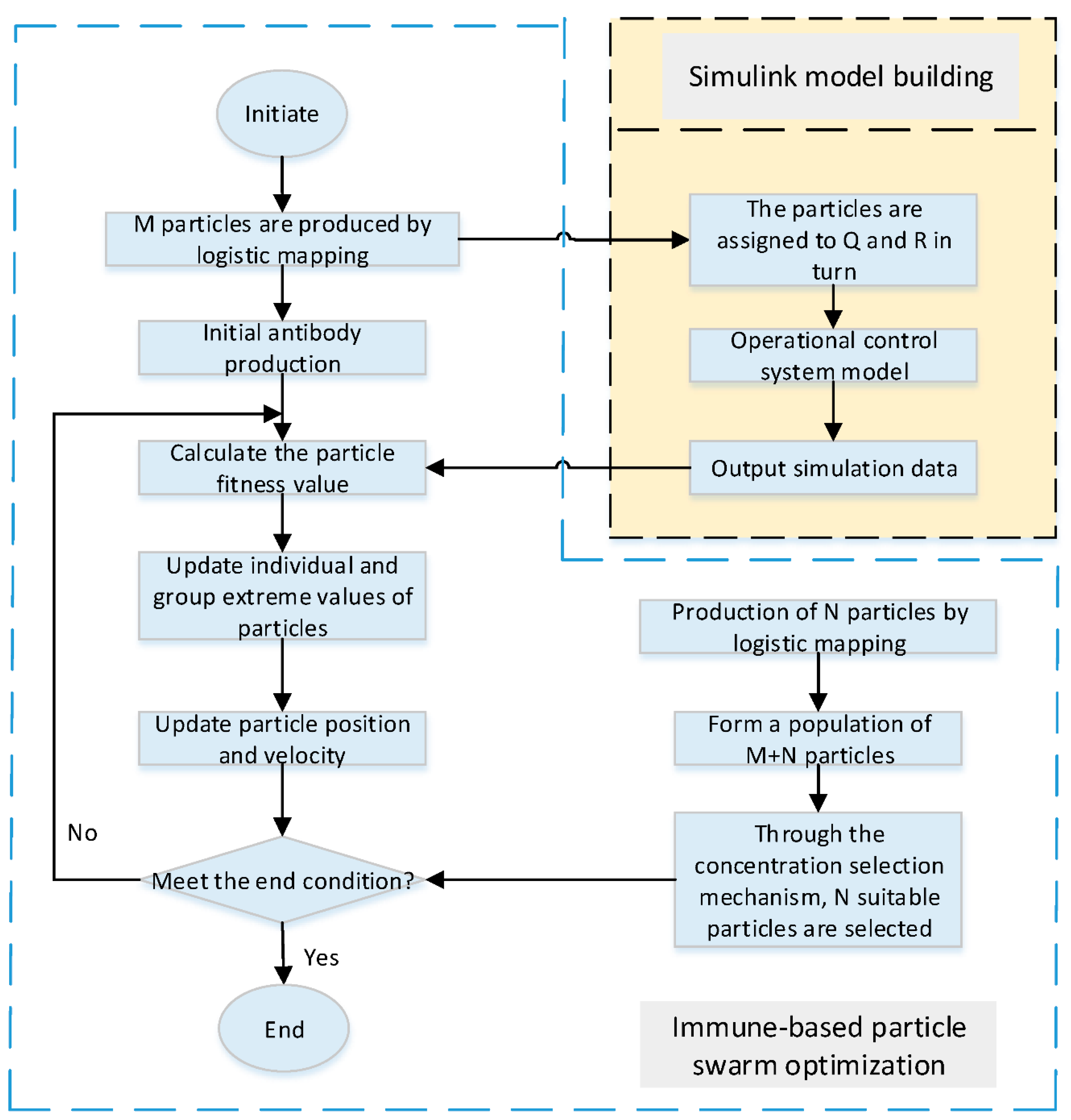
2.2.2. Optimizing the EKF Noise Covariance Matrix Using Immune-Based PSO

(a)
Elementary PSO:
PSO is a new type of evolutionary algorithm (EA) for solving optimization problems. Random particles search and follow the current optimal particle in the solution space and find the optimal solution through repeated iterations. In each iteration, the particles update themselves by tracking the individual extremum pbest and the global extremum gbest, and the particles always follow these two extremes to change their position and velocity until they find the optimal solution. PSO includes simpler rules than the genetic algorithm because it does not have the “crossover” and “variation” operations of the genetic algorithm, and it evaluates solution quality by the fitness of the solution [35]. When the two optimal values are found, the particle updates its velocity and position according to the following equation:
v i d = c 2 r 2 ( p g d x i d ) + c 1 r 1 ( p i d x i d ) + ω v i d x i d = v i d + x i d
where ω is the inertia weight, r2 and r1 are uniform random numbers in the range of [0, 1], c2 and c1 are learning factors, and Vid and Xid are the velocity and displacement numbers of the particles, respectively.
(b)
PSO based on adaptive weights of immunity:
Adaptive weights refer to the fact that ω changes dynamically depending on the position of the particle [35], with the inertia weight being related to the distance of the particle from the global optimum. Thus, the inertia weight of each different particle increases not only with the number of iterations but also with the distance from the global optimum, as follows:
ω = ω min ( f f min ) ( ω max ω min ) f a v g f min , f f a v g ω max , f > f a v g
where f, fmin, and favg denote the real-time objective function value of particles, the minimum objective value, and the average value of all particles, respectively. ω changes with f. When f is consistent, ω increases; when f is dispersed, ω decreases.
Immune-based PSO is used to update the antibody population on the basis of the immune algorithm, which can address the slow convergence of the immune algorithm. The steps of the immune-based hybrid PSO algorithm are as follows [35].
(1) Determine c2 and c1 (the learning factors) and M (the number of antibody populations).
(2) Map the initial antibody population P0 by logistic regression analysis to produce M antibodies of xi and vi where i = 1, 2, …, M.
(3) Produce immune antibodies. Calculate the adaptation value of the antibody in the current P. Determine whether the algorithm meets the end condition and output the result if yes; otherwise, continue to run.
(4) Update pbest and gbest, and update vi,j and xi,j according to the following equations:
v i , j ( t + 1 ) = c 2 r 2 [ p g , j x i , j ( t ) ] + c 1 r 1 [ p i , j x i , j ( t ) ] + ω v i , j ( t ) x i , j ( t + 1 ) = v i , j ( t + 1 ) + x i , j ( t ) , j = 1 , 2 , , D
(5) Generate N new antibodies by logistic mapping.
(6) Select concentration-based antibodies. The probability of producing N + M new antibodies is calculated using the percentage of similar antibodies in the population. N antibodies are selected according to their probability of forming antibody cluster P. Then, return to step (3).
(c)
PSO based on adaptive weights of immunity optimization of the EKF covariance matrix by a novel particle swarm:
The selection of system matrices Q and R is crucial for the convergence and stability of the EKF system. The noise covariance optimization adjusts the parameters within the Q and R matrices in each simulation cycle. Each particle corresponds to a set of parameters, and the system is iterated several times. In each iteration, the system simulation results are calculated to obtain the fitness values of the particles, and the individual global optimal positions are obtained according to the fitness values. At the end of the iteration, the global optimal particles are obtained as the parameters of the noise covariance matrix [36]. The immune-based PSO algorithm optimizes the parameters of the EKF. The flow chart of this algorithm is shown in Figure 1.
In this paper, root mean square error (RMSE) is used to evaluate the performance index of the control system, and the fitness function is selected as:
f u n = { [ i = 1 n ( ω r e f ω i ) ] / n } 1 / 2
where ωref and ωi are the actual and estimated rotational speeds, respectively, and n is the simulation time divided by the sampling period and is the number of samples.
For the Q and R matrix settings, there are a total of six parameters to consider, each of which is set in the range of [10−10, 200]. Because of the large selection range of each parameter, assembly is slow and includes determining an optimal value for each parameter (within the applied range) such that the overall control effect is optimized. The immune-based adaptive weight method is thus adopted for particle swarm optimization of these six parameters so that the composition of matrices Q and R leads to obtaining the optimal matrix and finally derive the optimal control parameter through convergence.
The specific implementation process initializes the population of 30 groups as a 6-dimensional parameter matrix, and this initialization of the array for each parameter value range is [10−10, 200], randomly selected to constitute a 6-dimensional matrix through the particle swarm algorithm. The algorithm calculates the optimal value of the fitness function (i.e., the average of the error between the actual rotational speed and the set rotational speed of the smallest value) and records the position of its particle and speed. After the calculation is run for a certain time, it selects 30 population groups and then restarts the search for the optimum values. The optimal data are saved to be immune to recording, and the adaptive weights are ultimately found for the optimal value of the 6-dimensional array.

2.2.3. Optimizing the EKF Noise Covariance Matrix using Immune-Based PSO Convergence Analysis of the Novel PSO Algorithm

To verify the feasibility and rationality of the improved novel PSO algorithm, this paper uses PSO and the novel PSO algorithm to optimize the EKF and simulate and verify it in MATLAB. The parameters are set as shown in Table 1 below.
Under the parameter settings in the table, by comparing the convergence curves of the fitness function of the PSO algorithm with basic adaptive weights and adaptive weights combined with immune algorithms under the PI and SMC, the EKF is shown to have a delay effect. This indicates that the estimated speed lags behind the actual speed during the rise of the actual motor speed. Therefore, the final convergence value is close to 0 but does not completely reach 0. Figure 2 shows the convergence curves of the fitness function under various algorithms, where the vertical axis is the convergence process, and the horizontal axis represents the number of iterations.
Table 2 and Table 3 show a few randomly selected data from several simulation experiments for comparison. The data show that SMC-w-IPSO has a stronger searching ability and can improve the accuracy of the search optimization. The SMC-w-PSO can maintain a higher speed of searching optimization.

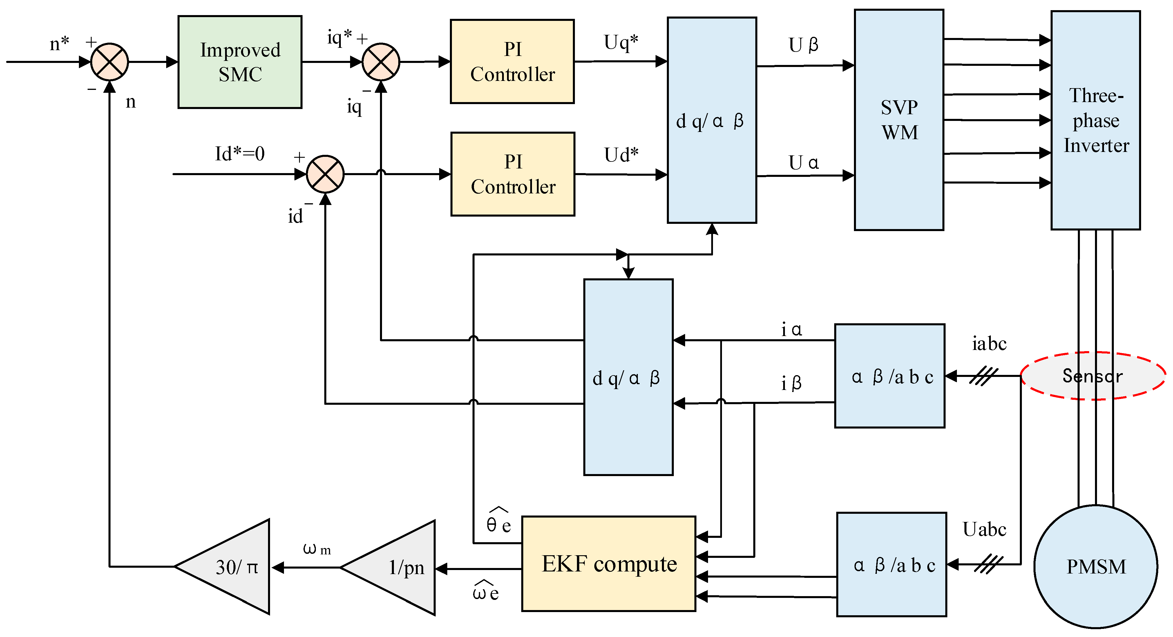
3. Design of the Speed Controller Based on Improved SMC

This section introduces the design of the SMC-based speed controller, including the design of the traditional speed SMC, the improvement in the velocity SMC, the stability proof of the controller, and the analysis of the new approach law.

3.1. Design of Traditional-Speed SMC

The mathematical model of the HSPMSM in the d-q coordinate system is as follows [37]:
u d = R i d + L s d i d / d t p n ω e L s i q u q = R i q + L s d i q / d t + p n ω e L s i d + p n ω e φ f J d ω e / d t = 1.5 p n φ f i q T L
where id, iq, and Ud, Uq are the current components and voltage components in the d-q coordinate system, respectively, pn is the polar logarithm, and the other characters are used as in Equation (1).
The HSPMSM uses rotor magnetic field orientation control with id = 0, defines x 1 = ω r e f ω e , x 2 = x 1 · = ω e · as the system state variables and uses u = i q · , D = 3 p n φ f / 2 J to obtain the system state equation as:
x 1 · x 2 · = 0 1 0 0 x 1 x 2 + 0 D u
The SMSs—the LSMS, GSMS, and ISMS—are used to design the normal SMC, global SMC, and integral SMC for control. Because the GSMC is robust in both converging and sliding modes, it has better robustness than the normal SMC. The integral SMC, which is obtained by introducing an integral term in the SMS, can suppress the steady-state error of the system and enhance the robustness of the system. In this paper, three types of SMSs are applied separately for convergence law improvement. An optimal controller is selected by Lyapunov stability proof and characteristic analysis for subsequent simulation verification [27].
The linear SMS function is defined as:
s = c x 1 + x 2
where c indicates the parameter to be designed, and c > 0.
To ensure that the HSPMSM has favorable dynamic quality, the exponential convergence law method is normally adopted, where the exponential convergence law function is Formula (14), and the obtained controller expression is Formula (15):
s · = ε sgn ( s ) q s
u = [ c x 2 + ε sgn ( s ) + q s ] / D
The global SMC function is defined as:
s 1 = x 2 + c 1 x 1 h ( 0 ) exp ( λ t )
where h ( 0 ) = x 2 ( 0 ) + c 1 x 1 ( 0 ) , c 1 > 0 , λ > 0 . The SMC using the global SMS and exponential convergence law is as follows:
u 1 = [ c 1 x 2 + λ h ( 0 ) exp ( λ t ) + ε sgn ( s 1 ) + q s 1 ] / D
The integral SMS function is defined as:
s 2 = x 2 + c 2 x 1 + c 3 0 t x 1 d t
where c 2 > 0 , c 3 > 0 . The SMC using the integral SMS and exponential convergence law is as follows:
u 2 = [ c 2 x 2 + c 3 x 1 + ε sgn ( s 2 ) + q s 2 ] / D

3.2. Improvement of Speed SMC

The exponential convergence law is improved to further reduce the convergence time to the SMS and to increase the convergence speed, which causes jitter in the system due to overly fast convergence [37]:
s · = [ ξ arctan x 1 ] s a t ( s ) / [ η exp ( δ s ) ] q s
where η, δ, ε, and q are constants greater than 0.
The exponential term e δ s is thus introduced into the system. When s is large, that is, when the system state is far from the SMS, the exponential term approaches 0, the isokinetic term εsgn(s) is amplified, and the system accelerates to approach the SMS under εsgn(s) and qs. When s approaches 0, the exponential term approaches 1 and gradually fails. η can adjust the distance from the sliding mode to the system state whose denominator is near 0. Furthermore, the boundedness of the range of the inverse tangent function ensures that the speed is not overly large and avoids system chattering. In addition, sat(s) is used instead of sgn(s) to further weaken the chattering phenomenon of the system.
s a t ( s ) = 1 k s 1 s < s s > k = 1 /
The improved asymptotic LSMC, GSMC, and ISMC are obtained from the above as follows:
u = { c x 2 + [ ε arctan x 1 s a t ( s ) ] / [ η exp ( δ s ) ] + q s } / D
u 1 = { c 1 x 2 + λ h ( 0 ) exp ( λ t ) + [ ε arctan x 1 s a t ( s 1 ) ] / [ η exp ( δ s 1 ) ] + q s 1 } / D
u 2 = { c 2 x 2 + c 3 x 1 + [ ε arctan x 1 s a t ( s 2 ) ] / [ η exp ( δ s 2 ) ] + q s 2 ] } / D

3.3. Controller Stability Proof

The stability proof of the novel convergence law is performed using a Lyapunov function. The Lyapunov function is obtained as follows [38]:
V = s 2 / 2
When the Lyapunov stability theorem, V · = s s · 0 , is satisfied, the system is stable. In this system, the following holds true:
V · = s s · = [ ε arctan x 1 s a t ( s ) · s ] / [ η exp ( δ s ) ] q s 2
In the formula, ε and η are constants greater than 0, and sat(s) has the same sign as s, so V · = s s · 0 is valid. This improved convergence law satisfies the Lyapunov stability theorem and the sliding mode arrival condition, which enables the system to arrive near the origin from any position in the phase space in finite time, i.e., convergence is always achieved.

3.4. Controller Stability Proof Analysis of New Approach Law Characteristics

The common second-order system is considered as an example in MATLAB to conduct simulation verification and analysis on the traditional and new improved convergence laws. The controlled object is set as [37]:
θ · · = f ( θ , t ) + b u ( t )
where f ( θ , t ) = 25 θ · ; b = 133; and u(t) is the controller. The sliding form surface is as follows:
s = 15 e + e ·
After taking the two convergence laws u and u 2 separately, we obtain:
u 3 ( t ) = [ ξ sgn ( s ) + q s + 15 e · + θ * · · + f ( θ , t ) ] / b
u 4 ( t ) = { [ ξ arctan x 1 s a t ( s ) ] / [ η exp ( δ s ) ] + q s + 15 e · + θ * · · + f ( θ , t ) } / b
First, the simulation verifies the influence of q in the exponential convergence law, taking q = 0, q = 10, q = 20, and q = 30. As shown in Figure 3, the larger the value of q is, the earlier the convergence.
Second, in Formulas (27)–(30), the initial state is [−0.15–0.15], θ* = cos(t), η = 0.001, δ = 0.015, ε = 5, ∆ = 0.2, and q = 10. The simulations of u3(t) and u4(t) are shown in Figure 4 and Figure 5, respectively.
The results show that there is minimal difference between the controllers of the convergence law design in terms of the tracking angle and angular velocity by comparing and analyzing Figure 4a,b and Figure 5a,b. The controller control inputs in Figure 4c and Figure 5c clearly show that the controller with the improved convergence law design is much better. Simultaneously, according to the phase trajectory comparisons in Figure 4d and Figure 5d, we determine that the improved exponential convergence law greatly reduces the convergence time, can converge to the slip surface quickly, and converge to the equilibrium point. Therefore, according to the simulation verification of the improved convergence law of the SMC compared with the traditional SMC output chattering reduction, chattering is significantly reduced.

4. Case Study

Reports should discuss not only their results but also how they can be interpreted from the perspective of previous studies and their own working hypotheses. These findings and their implications should be discussed in the broadest possible context possible, and future research directions may also be highlighted.
To verify the feasibility and effectiveness of the optimization scheme here, as well as the superiority of the improved SMC and EKF based on the immune PSO algorithm, a simulation model of the flywheel HSPMSM system based on the EKF is built using MATLAB and Simulink.
The model consists of the HSPMSM, SVPWM converter, and controller. The improved SMC replaces the PI controller and is obtained by the EKF based on the immune PSO. The id = 0 vector control strategy is adopted, and the immune particle swarm algorithm optimizes the six-dimensional array synthesized using the EKF covariance matrices Q and R, namely, the optimal values of 6 parameters. Then, the estimated rotational speed and rotor angle position are calculated using the EKF. The selected flywheel motor parameters are shown in Table 4. Figure 6 shows the improved sensorless vector control block diagram of the HSPMSM based on the EKF. The traditional control strategy uses a PI controller for both the outer loop of speed and the inner loop of current, whereas in this thesis, a new SMC controller with an improved convergence law is used to replace the outer loop PI controller to control the speed, after which all the comparison graphs of the simulation results refer to the comparison of the control results under the two control strategies of the outer loop PI controller and the outer loop of the improved SMC controller.
Two experiments are conducted here. The system speed is set at 1000 rpm and 8000 rpm, PI and SMC control are improved, and then comparative analysis is performed after improving the optimization algorithm.

4.1. Simulation Experimental Design

We adopt the dual closed-loop control strategy with a current inner loop and a speed outer loop. The outer-loop controller adopts the improved SMC. The four inputs of the EKF depicted in Figure 6 are iα, iβ, uα* and uβ*. The EKF algorithm is used for the online state estimation of angular velocity ωe and position angle θe. The whole system is optimized by iterative operations using the IPSO algorithm, and the appropriate noise covariance matrix is selected to achieve the optimal EKF estimation [37].

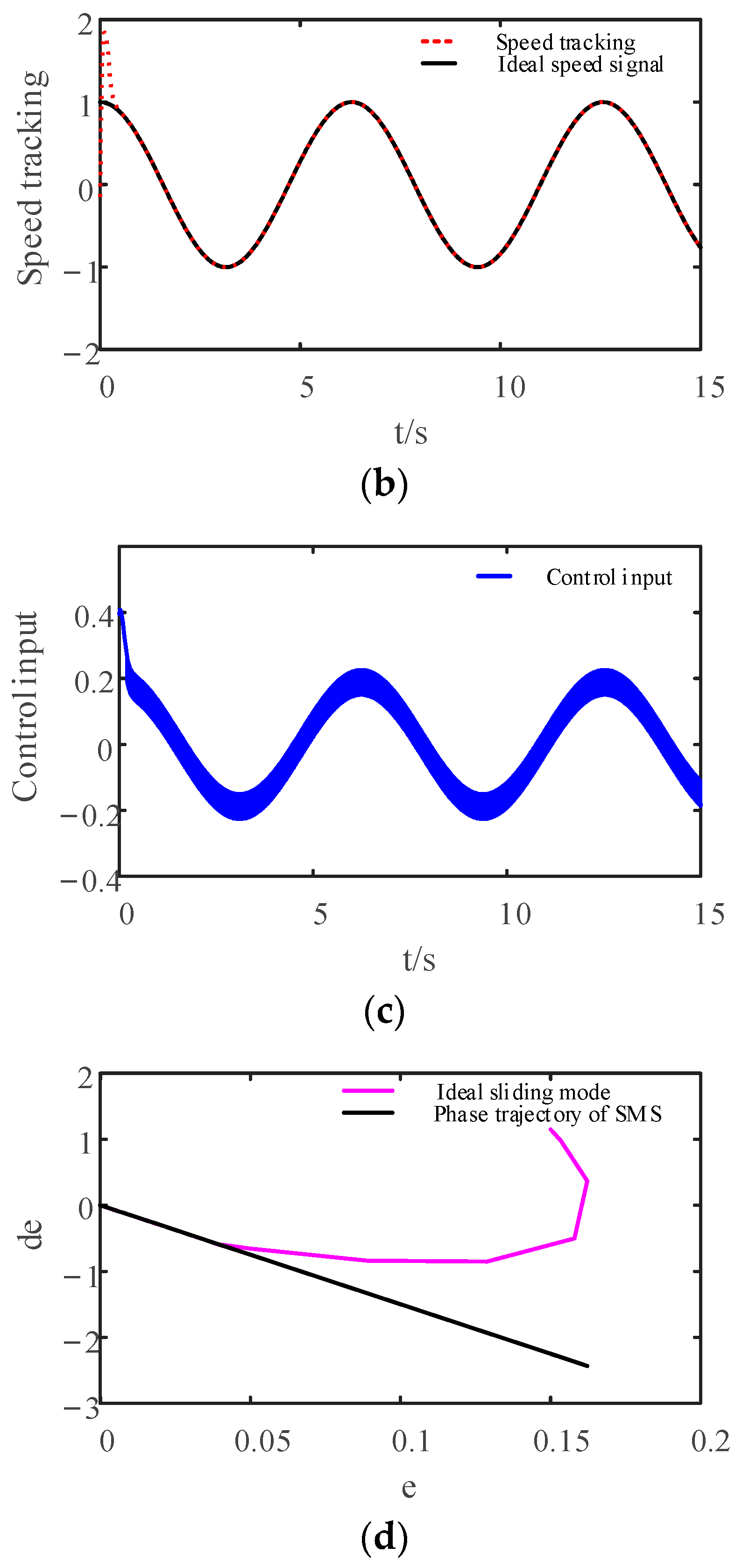
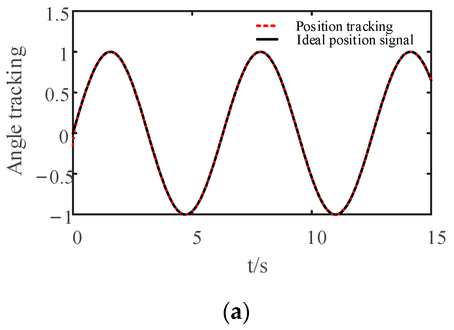
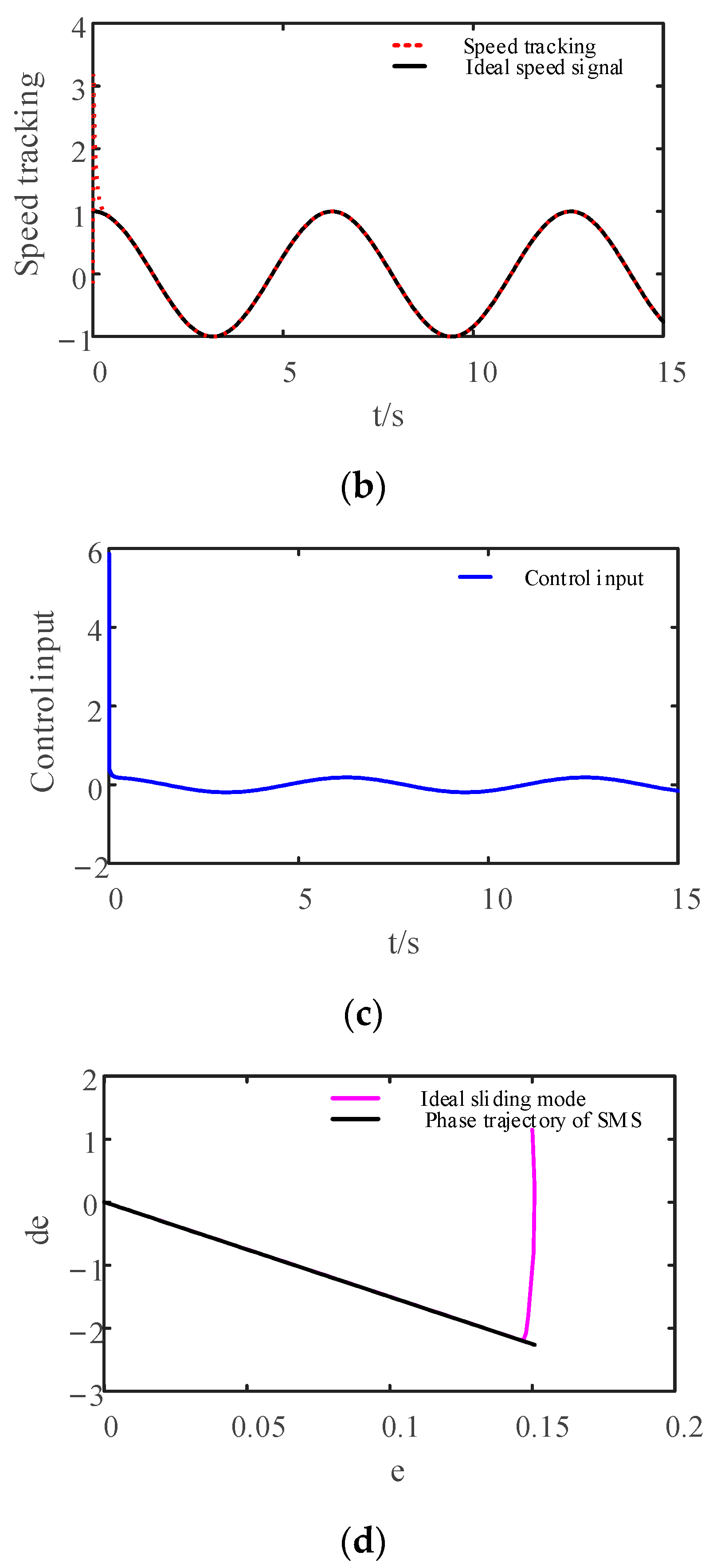
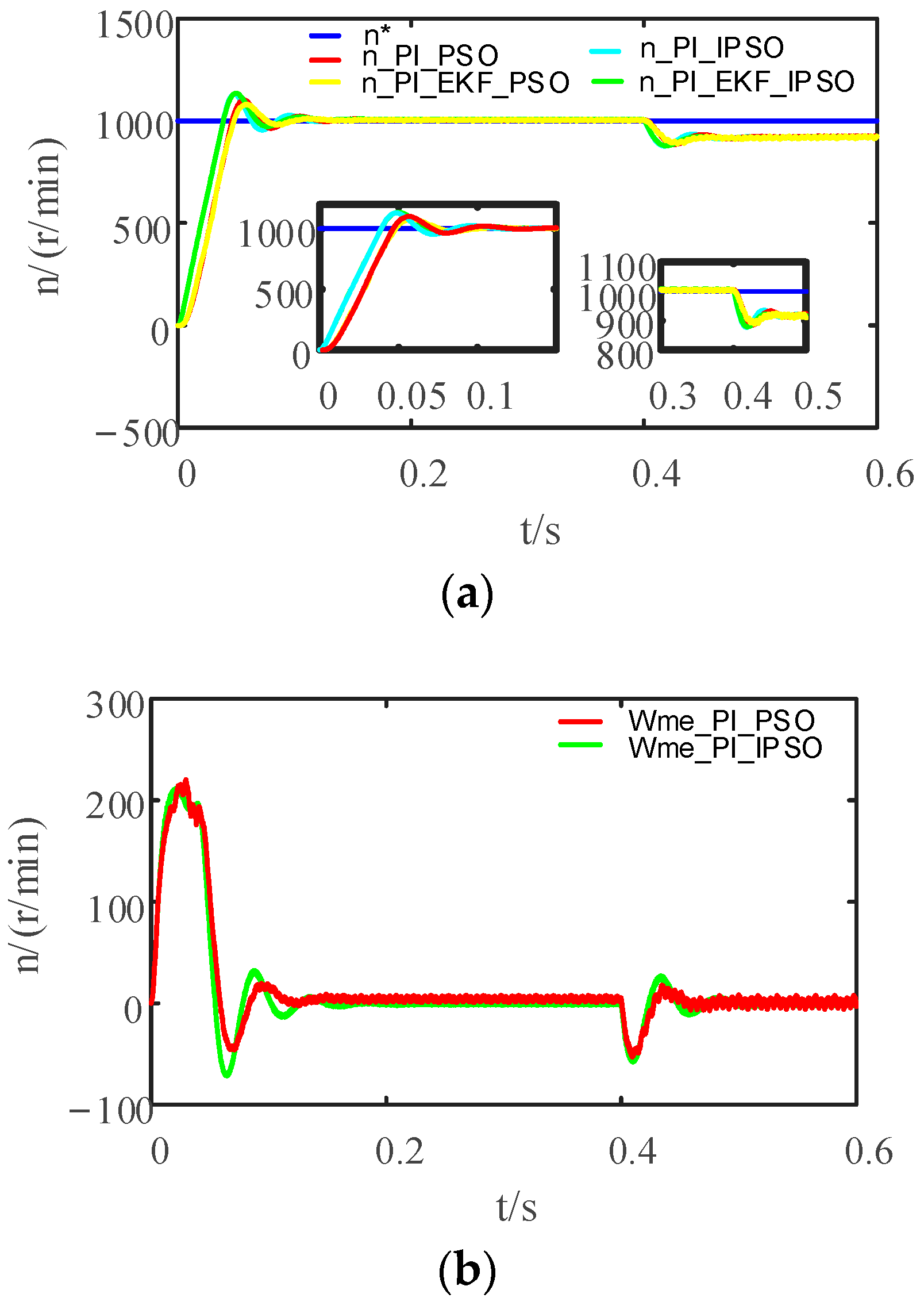
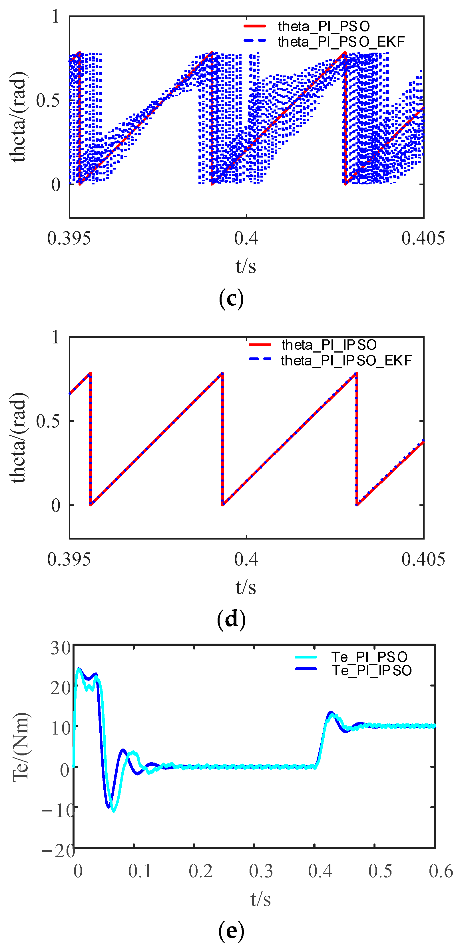
4.2. Simulation Experiment I

In the first experiment, the reference speed is first set as n* = 1000 rpm with a no-load startup condition. The total simulation duration is 0.6 s, and the disturbance load Tm = 10 is suddenly added at 0.4 s. Figure 7 shows the speed comparison diagram, speed error diagram, rotor position angle diagram, and electromagnetic torque diagram of the motor under the EKF matrix parameter control strategy optimized using the basic PSO algorithm and the immune PSO algorithm under the PI controller. Figure 8 shows the speed comparison diagram, speed error diagram, rotor position angle diagram, and electromagnetic torque diagram of the motor under the EKF matrix parameter control strategy optimized using the basic PSO algorithm and immune PSO algorithm under the improved SMC controller.
According to the rotational speed curves in Figure 7a and Figure 8a, Table 5 lists the dynamic performance indexes from 0 to 1000 rpm, including the static performance indexes when stabilized at 1000 rpm and the comparison of the dynamic and static indexes after 0.4 s and application of the load.
Table 5 and Figure 7a and Figure 8a show that the estimated rotational speed value of the EKF based on the elementary PSO algorithm under either the PI controller or improved SMC controller fluctuates within a range after sudden load addition, oscillates and does not stabilize at a fixed value, while the estimated rotational speed value of the EKF based on the immune PSO algorithm can stabilize at 923.1 rpm and 1001 rpm. Therefore, the data show that the parameters of the EKF covariance matrix obtained using the optimization of the immune PSO algorithm are better than those obtained using the optimization of the elementary PSO algorithm. The rise time, peak time, and regulation time under both the PI and SMC controllers are all within 0.2 without much difference, but the overshoot magnitude using the improved SMC control is significantly less than that of the PI controller. The improved SMC controller is also shown to be more resistant to disturbances and more stable by comparing the steady state error and load recovery time after sudden load application. A comparison of the speed difference between Figure 7b and Figure 8b shows that the value of the SMC speed error is very small and almost negligible, but the control under the PI controller is clearly affected. The parameters of the particle swarm search with the same controller improved using the immune algorithm are significantly better than those optimized by the basic particle swarm algorithm in terms of steady-state performance, and the degree of curve smoothing is shown to be superior. The electromagnetic torque comparison diagram of the motor shows that the control strategy after immune PSO under the control of the improved SMC controller is the best. There is no significant difference between the rotor position angle PI and SMC control effect, both of which are optimized using the immune particle swarm optimization algorithm.

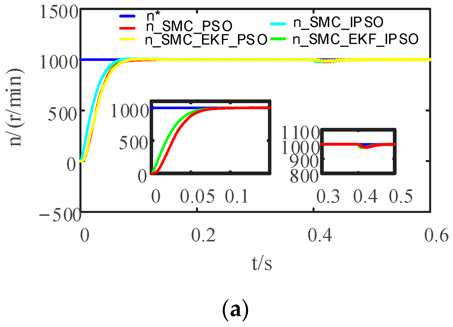
4.3. Simulation Experiment II

In the second experiment, the flywheel motor speed is set to n* = 8000 rpm with a no-load startup. The total simulation duration is 1 s, and the disturbance load Tm = 10 is suddenly added at 0.4 s. Figure 9 shows the speed comparison diagram, speed error diagram, rotor position angle diagram, and electromagnetic torque diagram of the motor using the EKF matrix parameter control strategy optimized by the immune PSO algorithm under the PI controller. Figure 10 shows the speed comparison diagram, speed error diagram, rotor position angle diagram, and electromagnetic torque diagram of the motor under the EKF matrix parameter control strategy optimized by the immune PSO algorithm using the improved SMC controller.
Comparing the speed tracking and speed error graphs in Figure 9 and Figure 10 shows that the PI controller’s system response time under the immune PSO optimization algorithm is within 0.3 s. Under the improved PSO optimization algorithm, EKF matrices R and Q obviously perform poorly. Speed is not completely tracked after it reaches 8000 rpm, and the speed error fluctuates greatly. The fluctuation of electromagnetic torque is also relatively large. However, although the system response time of the improved SMC controller under the immune PSO optimization algorithm is slow, reaching 8000 rpm when it is close to 0.7 s, the tracking effect under load is still very favorable. Basically, the motor speed observed using the EKF algorithm can fully track the actual measured value of the HSPMSM, and the control effect is relatively favorable. Under both control strategies, the load starts at 0.4 s and does not have a large impact on the system. The accuracy of motor speed estimation is greatly improved by the improved control system, and the error between the estimated and actual values of motor speed is greatly reduced.
According to the rotational speed curves in Figure 9a and Figure 10a, Table 6 lists the dynamic performance indexes from 0 to 8000 rpm, the static performance indexes when stabilized at 8000 rpm, and the comparison of the dynamic and static indexes with the load applied after 0.4 s.
Table 6 shows that the rotational speed under the PI controller fluctuates within a range of 7817~8242 and 7932~8107 for both the actual measured value and the estimated value of EKF optimized using IPSO, and the measured and estimated values cannot be kept at a fixed value. The sudden loading of the system causes poor system stability performance and poor tracking ability. The improved SMC controller speed measurement is fixed at 8120, and the estimated value is between 8109 and 8126, with a speed difference of −11 to 6 rpm. After improvements to the controller, the accuracy of the system’s estimation of the motor speed is greatly improved, and the error between the estimated and actual values of the motor speed is greatly reduced.
In summary, the improved control system has a small drop in speed during sudden load addition and can quickly recover to the original state, which proves that this control system has favorable robustness and anti-load disturbance capability.

5. Conclusions

In this paper, a new type of control law SMC and an immune PSO algorithm are used to optimize the control system of an HSPMSM. The improved SMC adopts a new nonlinear function with better smoothness at the origin, which can weaken the chattering phenomenon. The system response time is 0.7 s, the overshoot is approximately 1.5, there is no oscillation, and the rotation speed error is 6 rpm. The system response time under the control of the PI controller is 0.3 s, and the overshoot is approximately 10, but the oscillation is obvious; it cannot keep tracking the actual speed completely, and the range of the speed error is [−300 300], the rotor position of the HSPMSM is extremely poorly tracked during the speed increase of 7500~8000 rpm, and the electromagnetic torque is also not 0. In conclusion, the control performance of the PI controller is not as favorable as that of the SMC in a high-speed steady state, while the dynamic response of the HSPMSM is faster at zero speed as well as in the middle and low speeds.
An improved EKF based on an immune algorithm is used to observe the motor speed. The control effect of the EKF algorithm based on immune-type PSO optimization is better than that of the EKF algorithm based on basic PSO optimization, and it is shown in the figure that the curves are smoother and do not jitter. The two simulation experiments consider operation at 0.4 s after the load is suddenly increased. The simulation results show that the improved control system can improve the interference immunity of the system and can effectively suppress the influence of sudden load changes on the speed. Simultaneously, the estimation accuracy of the speed and rotor position angle is high; thus, the system has strong robustness.
This study applies to the field of sensorless control of PMSMs at medium and high speeds. The new controller design and the new EKF sensorless position estimator algorithm can make the motor control system more accurate and precise in estimating the position state of the motor under the premise of stabilization.

Author Contributions

Conceptualization, K.M. and Q.L.; methodology, Q.L.; software, Z.Z.; validation, K.M., Q.L. and H.W.; formal analysis, H.F.; investigation, T.K.; resources, K.M.; data curation, Q.L.; writing—original draft preparation, Q.L.; writing—review and editing, K.M., Z.Z. and H.W.; visualization, H.F.; supervision, T.K.; project administration, K.M.; funding acquisition, K.M. All authors have read and agreed to the published version of the manuscript.

Funding

This research was funded by the Inner Mongolia Science and Technology Major Project, grant numbers 2020ZD0016 and 2021ZD0032. This research was funded by the Key Technology Research Project in Inner Mongolia under Grant 2020GG0281. This work was funded by the Basic Research Funds for Universities directly under the Inner Mongolia Autonomous Region under Grant ZTY2023033.

Institutional Review Board Statement

Not applicable.

Informed Consent Statement

Not applicable.

Data Availability Statement

The data supporting the findings of this study are available from the corresponding author upon reasonable request. The data are not publicly available due to privacy.

Conflicts of Interest

Author Haining Feng was employed by the company CNNC North Nuclear Fuel Element Co., Ltd. The remaining authors declare that the research was conducted in the absence of any commercial or financial relationships that could be construed as a potential conflict of interest.

References

  1. Alessandro, S.; Federico, D.; Gianluca, G.; Ignazio, M. Performance Analysis of PMSM for High-Speed Flywheel Energy Storage Systems in Electric and Hybrid Electric Vehicles. In Proceedings of the 2014 IEEE International Electric Vehicle Conference, Florence, Italy, 17–19 December 2014. [Google Scholar]
  2. Zhang, X.; Yang, J. An Improved Discharge Control Strategy with Load Current and Rotor Speed Compensation for High-Speed Flywheel Energy Storage System. In Proceedings of the IEEE Transactions on Industrial Electronics, Hangzhou, China, 22–25 October 2014. [Google Scholar]
  3. Liu, J.; Xiao, F.; Shen, Y.; Mai, Z.; Li, C. Position-Sensorless Control Technology of Permanent-Magnet Permanent-Magnet Synchronous Motor—A Review. Trans. China Electrotech. Soc. 2017, 32, 76–88. [Google Scholar]
  4. Hofer, M.; Nikowitz, M.; Schroedl, M. Sensorless Control of a Reluctance Synchronous Machine in the Whole Speed Range without Voltage Pulse Injections. In Proceedings of the 2017 IEEE 3rd International Future Energy Electronics Conference and ECCE Asia (IFEEC 2017-ECCE ASIA), Kaohsiung, Taiwan, 3–7 June 2017. [Google Scholar]
  5. Bolognani, S.; Zigliotto, M.; Zordan, M. Extended-Range PMSM Sensorless Speed Drive Based on Stochastic Filtering. IEEE Trans. Power Electron. 2001, 16, 110–117. [Google Scholar] [CrossRef]
  6. Favata, A.; Toso, F.; Torchio, R.; Bolognani, S. Integral Model Predictive Current Control for Synchronous Motor Drives. IEEE Tranactions Power Electron. 2021, 36, 13293–13303. [Google Scholar] [CrossRef]
  7. Wang, G.; Valla, M.; Solsona, J. Position Sensorless Permanent Magnet Synchronous Machine Drives—A Review. IEEE Trans. Ind. Electron. 2019, 67, 5830–5842. [Google Scholar] [CrossRef]
  8. Lee, Y.; Sul, S.K. Model-based Sensorless Control of an IPMSM with Enhanced Robustness against Load Disturbances based on Position and Speed Estimator using a Speed Error. IEEE Trans. Ind. Electron. 2017, 24, 1448–1459. [Google Scholar] [CrossRef]
  9. Andersson, A.; Thiringer, T. Motion Sensorless IPMSM Control Using Linear Moving Horizon Estimation with Luenberger Observer State Feedback. IEEE Trans. Transp. Electrif. 2018, 4, 464–473. [Google Scholar] [CrossRef]
  10. Bao, D.; Pan, X.; Wang, X. Adaptive Synchronous-Frequency Tracking-Mode Observer for the Sensorless Control of a Surface PMSM. IEEE Trans. Ind. Appl. 2017, 54, 6460–6471. [Google Scholar] [CrossRef]
  11. Xue, S.; Wei, L.; Ling, Y. Sensorless Vector Control of Permanent Magnet Synchronous Motor Based on Extended Kalman Filter. Electr. Control Appl. 2011, 38, 15–18. [Google Scholar]
  12. Li, Y.; Xie, L.; Qi, R.; Lin, H. Design of PMSM sensorless speed regulating system. Electr. Mach. Control 2003, 7, 307–309. [Google Scholar]
  13. Zheng, S.; Meng, K.; Hai, R.; Wang, T. Sensorless DPMSM sliding Mode on Particle Swarm Optimization EKF. Modul. Mach. Tool Autom. Manuf. Technol. 2022, 7, 66–70. [Google Scholar]
  14. Wang, A.; Wang, Q.; Hu, C.; Qian, Z.; Ju, L.; Liu, J. An EKF for PMSM Sensorless Control Based on Noise Model Identification Using Ant Colony Algorithm. In Proceedings of the 2009 International Conference on Electrical Machines and Systems, Tokyo, Japan, 15–18 November 2009. [Google Scholar]
  15. Ding, H.; Qin, X.; Wei, L. Extended Kalman filters combined with feed-forward compensation for permanent magnet synchronous motor position estimation. Control Theory Appl. 2016, 33, 1312–1318. [Google Scholar]
  16. Ding, H.; Qin, X.; Wei, L. Sensorless Control of Surface-Mounted Permanent Magnet Synchronous Motor Using Adaptive Robust UKF. J. Electr. Eng. Technol. 2022, 17, 2995–3013. [Google Scholar] [CrossRef]
  17. Janiszewski, D. Load Torque estimation in sensorless PMSM drive using Unscented Kalmana Filter. In Proceedings of the 2014 IEEE Interantional Symposium on Industrial Electronics, Gdansk, Poland, 27–30 June 2011. [Google Scholar]
  18. Aydogmus, O.; Sunter, S. Implementation of EKF based sensorless drive system using vector controlled PMSM fed by a matrix converter. Electr. Power Energy Syst. 2012, 43, 736–743. [Google Scholar] [CrossRef]
  19. Bolognani, S.; Oboe, R.; Zigliotto, M. Sensorless Full-Digital PMSM Drive with EKF Estimation of Speed and Rotor Position. IEEE Tranactions Power Electron. 2021, 46, 184–191. [Google Scholar] [CrossRef]
  20. Park, J.B.; Wang, X. Sensorless Direct Torque Control of Surface-Mounted Permanent Magnet Synchronous Motors with Nonlinear Kalman Filtering. Energies 2018, 11, 969. [Google Scholar] [CrossRef]
  21. Wang, X.; Cao, B.; Mahfuz Alam, S.M. Sensorless Direct Torque Control of Surface Permanent Magnet Synchronous Motors with Resilient Extended Kalman Filtering. In Proceedings of the 2017 IEEE Transportation Electrification Conference and Expo(ITEC), Chicago, IL, USA, 22–24 June 2017; pp. 714–719. [Google Scholar]
  22. Yi, B.; Kang, L.; Tao, S.; Zhao, X.; Jing, Z. Adaptive Two-stage Extended Kalman Filter Theory in Application of Sensorless Control for Permanent Magnet Synchronous Motor. Math. Probl. Eng. 2013, 2013, 974974. [Google Scholar] [CrossRef]
  23. Quang, N.K.; Ha, Q.P.; Hieu, N.T. FPGA Sensorless PMSM Drive with Adaptive Fading Extended Kalman Filtering. In Proceedings of the 2014 13th International Conference on Control Automation Robotics and Vision (ICARCV), Singapore, 10–12 December 2017. [Google Scholar]
  24. Khan, N.; Jabbar, A.; Bilal, H.; Gul, U. Compensated Closed-loop Kalman Filtering for nonlinear systems. Measurement 2020, 151, 1–11. [Google Scholar] [CrossRef]
  25. Park, J.B.; Wang, X. Nonlinear Filtering Based Sensorless Direct Torque Control of Surface-Mounted Permanent Synchronous Motors. Energies 2018, 11, 448–453. [Google Scholar]
  26. Xue, S.; Wei, L.; Ling, Y. Sensorless Vector Control of Permanent Magnet Synchronous Motors Based on EKF and SMC. Inf. Control 2012, 41, 267–272. [Google Scholar]
  27. Zhang, P.; Shi, Z.; Lin, J.; Yu, B.; Sun, Y.; Ding, H. Improved Sensorless Vector Control System for Permanent Magnet Synchronous Motors Based on Hyperbolic Tangent Functions. J. Harbin Eng. Univ. 2021, 42, 710–718. [Google Scholar]
  28. Hasan, D.E.; Hasan, K.; Afsin, K.A. A novel unified maximum power extraction framework for PMSG based WECS using chaotic particle swarm optimization derivatives. Eng. Sci. Technol.-Int. J.-Jestech 2021, 24, 158–170. [Google Scholar]
  29. Hasan, K. GM-CPSO A new viewpoint to chaotic particle swarm optimization via Gauss map. Neural Process. Lett. 2020, 52, 241–266. [Google Scholar]
  30. Hasan, D.E.; Afsin, K.A. Second-order sliding mode voltage-regulator for improving MPPT efficiency of PMSG-based WECS. Int. J. Electr. Power Energy Syst. 2020, 121, 106149. [Google Scholar]
  31. Xiuxing, Y.; Zhansi, J.; Li, P. Recurrent neural network based adaptive integral sliding mode power maximization control for wind power systems. Renew. Energy 2020, 145, 1149–1157. [Google Scholar]
  32. Xiong, L.; Li, P.; Wang, J. High-order sliding mode control of DFIG under unbalanced grid voltage conditions. Int. J. Electr. Power Energy Syst. 2020, 117, 105608. [Google Scholar] [CrossRef]
  33. Yu, Q.; Yan, S.; Zhao, H. Simulation Experiment of Sliding Mode Control Based on Simulink. Sci. Technol. Innov. Her. 2018, 35, 97–98. [Google Scholar]
  34. Yuan, L.; Hu, B.X.; Wei, K.Y.; Chen, S. Modern Permanent Magnet Synchronous Motor Control Principle and MATLAB Simulation; Beijing University of Aeronautics and Astronautics Press: Beijing, China, 2016; pp. 151–165. [Google Scholar]
  35. Wen, Z.; Sun, H. MATLAB Intelligent Algorithm; Tsinghua University Press: Beijing, China, 2017; pp. 108–144. [Google Scholar]
  36. Xing, Y.; Wang, X.; Yang, D.; Zhang, Z. Novel Stator flux linkage estimator and choice of its parameters. Electr. Mach. Control 2016, 20, 29–35. [Google Scholar]
  37. Liu, J. Sliding Mode Control Design and MATLAB Simulation the Basic Theory and Design Method, 4th ed.; Tsinghua University Press: Beijing, China, 2012; pp. 38–55. [Google Scholar]
  38. Yu, L. Modern Control Theory, 3rd ed.; Tsinghua University Press: Beijing, China, 2007; pp. 100–104. [Google Scholar]
Figure 1. PSO of the EKF process based on immune adaptive weights.
Applsci 13 12407 g001
Figure 2. Convergence curve of the algorithm fitness function.
Applsci 13 12407 g002
Figure 3. The approach process of the phase trajectory of the exponential approach law under different q values.
Applsci 13 12407 g003
Figure 4. Characteristic curve under the u3(t) control law. (a) Angle tracking. (b) Angular velocity tracking. (c) Control input. (d) Phase trajectory.
Applsci 13 12407 g004aApplsci 13 12407 g004b
Figure 5. Characteristic curve under the u4(t) control law. (a) Angle tracking. (b) Angular velocity tracking. (c) Control input. (d) Phase trajectory.
Applsci 13 12407 g005aApplsci 13 12407 g005b
Figure 6. An improved sensorless vector control block diagram for an HSPMSM based on an EKF.
Applsci 13 12407 g006
Figure 7. Comparison diagram of the EKF matrix parameter control strategy optimized using the basic PSO and immune PSO algorithms under the PI controller: (a) speed comparison diagram; (b) speed error diagram; (c) PSO rotor position angle diagram; (d) IPSO rotor position angle diagram; (e) motor electromagnetic torque diagram.
Applsci 13 12407 g007aApplsci 13 12407 g007b
Figure 8. Comparison diagram of the EKF matrix parameter control strategy optimized using the basic PSO and immune PSO algorithms under the improved SMC: (a) speed comparison diagram; (b) speed error diagram; (c) PSO rotor position angle diagram; (d) IPSO rotor position angle diagram; (e) motor electromagnetic torque diagram.
Applsci 13 12407 g008aApplsci 13 12407 g008b
Figure 9. Comparison diagram after optimizing the EKF using the immune PSO algorithm under the PI controller. (a) Speed comparison diagram; (b) speed error diagram; (c) rotor position angle diagram; (d) electromagnetic torque diagram of the motor.
Applsci 13 12407 g009
Figure 10. Comparison diagram after optimizing the EKF using the immune PSO algorithm under the SMC controller. (a) Speed comparison diagram; (b) speed error diagram; (c) rotor position angle diagram; (d) electromagnetic torque diagram of the motor.
Applsci 13 12407 g010
Table 1. Basic PSO and novel PSO algorithm parameters.
ParametersValue
Learning factor c12
Learning factor c22
Minimum weight wmin0.4
Maximum weight wmax0.9
Inertia weight w0.6
Initialized population number30
Maximum number of iterations50
Search space dimension D6
Table 2. Performance analysis of multiple optimization strategies.
ArithmeticIterationsValueIterationsOptimal Fitness Value
PI-PSO1271.28783209182684826.7295406097632
SMC-PSO1229.10135431767954726.8191574261835
SMC-w-PSO1231.24745903278854525.9442102638115
SMC-w-IPSO1225.34971599980084617.3148124002699
Table 3. Performance analysis of multiple optimization strategies.
ArithmeticIterationsValueIterationsOptimal Fitness Value
PI-PSO1767.08647120521342952.057357828006
SMC-PSO629.10135431767954726.8191574261835
SMC-w-PSO426.6556819783912426.6556819783912
SMC-w-IPSO1724.2722685955334917.0101770076945
Table 4. Parameters of the HSPMSM.
ParametersValue
Stator Inductance/μH91.3
Stator Resistance/mΩ8.17
Rated Voltage/V690
Number of Motor Poles2
Rated Power/kW75
Friction Coefficient/Nms/rad0
Flywheel Moment of Inertia/kgm20.115
Busbar Capacitance/mF3
Bus Voltage Rating/mF1100
Minimum Speed/rpm10,000
Maximum Speed/rpm20,000
Table 5. Comparison of dynamic and static performance at 1000 rpm under PI and SMC controllers.
ParametersPI_PSOPI_EKF_PSOPI_IPSOPI_EKF_IPSOSMC_PSOSMC_EKF_PSOSMC_IPSOSMC_EKF_IPSO
rising time(tr)/s0.04650.04810.03890.03900.08450.12920.06990.1378
peak time(tp)/s0.05660.05850.04850.05020.10010.15420.08470.1684
Adjusting time(ts)/s0.07990.08490.07530.07630.12930.10470.06980.1396
overtone(σ)/%7.3569.53312.63712.5870.40.81.10.2
steady-state error/rpm765947−3.51
0.4 s after load recovery time/s0.04630.04630.04670.04630.0590.0560.07690.0729
0.4 s after load recovery value/rpm928.4919.9932.5923.1100110009961001
0.4 s after load recovery value fluctuation range/rpm928.4912~925932.5923.1990~1005991~1007996~9971001
Table 6. Comparison of dynamic and static performance at 8000 rpm under PI and SMC controllers.
ParametersPI_IPSOPI_EKF_IPSOSMC_IPSOSMC_EKF_IPSO
rising time(tr)/s0.28620.24530.76910.7666
peak time(tp)/s0.44760.24670.99360.9979
Adjusting time(ts)/s0.48860.250.99490.9989
overtone(σ)/%2.840.9751.51.575
steady-state error/rpm242107120126
0.4 s after load recovery value/rpm8242810781208126
0.4 s after load recovery value fluctuation range/rpm7817~82427932~810781208109~8126
Disclaimer/Publisher’s Note: The statements, opinions and data contained in all publications are solely those of the individual author(s) and contributor(s) and not of MDPI and/or the editor(s). MDPI and/or the editor(s) disclaim responsibility for any injury to people or property resulting from any ideas, methods, instructions or products referred to in the content.

