1. Introduction
Hand injuries are the most common type of injury we experience during our professional work. Their percentage, compared to all injuries, is 20–65%. Hand injuries sustained at work are much more severe compared to injuries sustained in other circumstances and require an extended period of treatment. It is impossible to completely avoid hand injuries during professional work because, in 90% of cases, injuries occur because of unpredictable and accidental human error [
1,
2]. Gloves protecting against hot thermal factors are defined as gloves that protect the user’s hands against heat from flames and hot surfaces of solids (e.g., metallurgical and blacksmith tools), hot liquids (e.g., molten metals), and gases (e.g., air heated by fire). Hot factors may occur in the form of radiant heat, convection heat, contact heat, flame, molten metal, or small splashes of molten metal. The possibility of protection against hot factors in industries such as metallurgy, welding, or foundry is a complex issue that requires a comprehensive approach and providing the employee with appropriate personal protective equipment [
2]. Gloves intended to protect hands against hot factors, like other parts of protective clothing (firefighter garments [
3,
4,
5], sleeping bags for newborns [
6,
7], civilian clothing [
8,
9,
10,
11,
12,
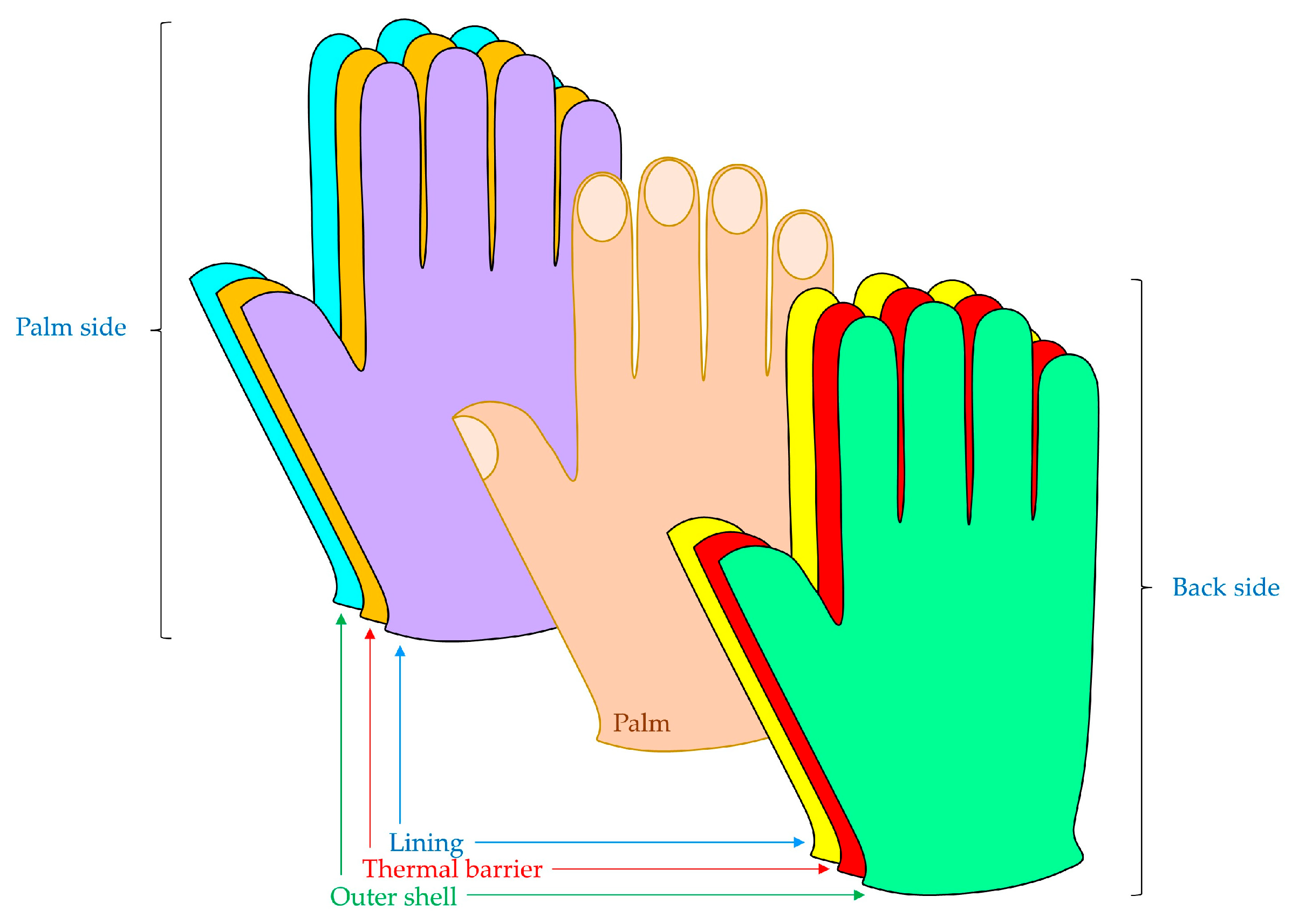
13]), are usually made of various materials or multilayer material systems (
Figure 1).
Due to their functions, the palm side and back side of the protective glove may differ in geometry and raw material composition, but both sides must be made of flame-retardant materials and meet appropriate thermal insulation standards. To produce this type of glove, mainly knitted fabrics or non-woven fabrics are used from yarn derived from Twaron, Kevlar, Basalt, Basofil, Nomex, and Preox fibers, flame-retardant impregnated wool yarn, cotton yarn, animal skins subjected to heat-resistant tanning, and aluminized fabrics made of Kevlar, Basalt, Nomex, and Twaron fibers [
14].
An example of gloves protecting against hot factors are gloves intended for workers in the metallurgical industry and for steel workers. In this type of glove, the back side, along with the cuff, is made of aluminized fabrics made of aramid fibers or glass fibers. In addition, a lining made of flame-retardant, impregnated cotton fabric is also used. The palm side of the glove is made mainly of fabric obtained from yarn made of non-flammable fibers or heat-resistant leather. In the glove, thermal insulation inserts, available in various non-woven fabrics, are placed between the lining and the outer fabric.
In the case of protective gloves, it is very difficult to achieve a balance between appropriate functional properties (physiological and sensory comfort) and ensuring appropriate protective properties. Protective gloves with a higher level of protection in terms of thermal insulation are usually made of several layers of various materials, which leads to a significant limitation of manual skills [
14].
Basalt fibers are used in personal protective equipment because the products made of them are characterized by low moisture absorption, low thermal conductivity, and good thermal insulation in the temperature range from −260 °C to +800 °C [
15,
16]. Additionally, basalt fibers are characterized by good resistance to chemicals, including alkalis and acids [
15]. Due to the non-flammable properties of basalt fibers, materials made of them are resistant to flames for a long time [
17,
18]. Moreover, they are resistant to microorganisms, UV radiation, and corrosion. They are characterized by a Limited Oxygen Index (LOI > 70%). This indicator is defined as the minimum concentration of oxygen contained in the mixture of oxygen and nitrogen necessary to maintain the combustion process. Basalt fabrics used without any coating may cause irritation to the skin, respiratory tract, and eyes [
19].
Products made of basalt fibers do not emit toxic products in reaction with air or water. Currently, basalt fibers are produced in the form of filaments that are not harmful to humans and do not cause carcinogenic effects, due to the fact that only filaments with thicknesses greater than 5 µm are subjected to the spinning process [
2,
15].
The modification of basalt fabrics for use in protective gloves was conducted by the Central Institute for Labor Protection—National Research Institute in cooperation with the Lodz University of Technology. A project called “Baglo” was conducted, which involved developing and finding a new solution for protective gloves made of basalt fibers intended for use in hot workplaces. The developed protective gloves were made of basalt fabric and were intended for protection in a hot work environment. As a result of the tests, only one fabric was resistant to contact heat at a contact temperature of 250 °C. It was a fabric made of basalt fibers and aluminized on one side, with a thickness of 2.13 mm and a mass per unit area of 1307 g·m
−2. This fabric was too thick for use in the palm part of the protective glove. In addition, the aluminum layer abraded and cracked at the seams during the fabrication process [
2,
16].
The subject and goal of the research presented in the current article were two composites with potential use in metallurgical gloves, which were developed on the basis of basalt fabric covered with two previously unused types of coatings (parylene C, TiO
2-ZrO
2-Al) in order to increase the insulation of the palm part of the gloves against contact heat at a contact temperature of 250 °C while maintaining high insulation against radiant heat. The first of the composites produced contained a coating of parylene C, the mer of which is shown in
Figure 2.
Parylene is the name used for the xylylene polymer family. These are polymers formed on the surface of the substrate by vacuum deposition polymerization. The advantages of parylene layers are low solubility, very good mechanical properties, high chemical resistance, and low permeability to gases and ions [
20]. Parylene coatings provide maximum barrier protection due to their high cohesion [
21]. The parylene coating reproduces the surface texture of the base material very well [
22]. Moreover, the polymer based on poly-para-xylylene has a very low thermal conductivity [
23]. Due to its availability and physicochemical properties, parylene C is the most frequently used (over 80%) type of parylene [
24,
25,
26,
27,
28]. Parylene C is an organic coating without plasticizers, solvents, or catalysts with a controlled deposition layer thickness [
20]. Additionally, it is characterized by specific properties for medical applications, e.g., low water absorption, low friction coefficient, high dielectric constant, and moderate elongation at break [
21]. The variety of parylene C coatings makes them suitable for a wide range of applications. Parylene C also shows high biocompatibility, biostability, and the ability to produce a thin, continuous, and inert coating [
22,
29]. In order to produce a second composite with ZrO
2-TiO
2-Al coatings deposited on its selected components using the physical vapor deposition (PVD) process, a mixture of zirconium dioxide (ZrO
2), titanium dioxide (TiO
2), and Al was used. ZrO
2 and TiO
2 were used because both ceramic materials belong to the group of thermal insulating coatings. Such coatings are primarily characterized by low thermal conductivity, a lack of transformation phase between the working temperature and room temperature, as well as good adhesion to the metallic substrate and chemical inertia. Titanium dioxide is mainly used in optics but also in cosmetics in the form of a mineral sunscreen filter, reflecting UV radiation, and in tissue engineering. Titanium dioxide was used in the deposited coating because it stabilizes the properties that zirconium dioxide loses due to aging in ambient conditions, and it also has good insulating properties. The aluminum coating was embedded in the outer part of the composite because it reflects thermal radiation very well [
2,
29,
30,
31].
2. Materials and Methods
2.1. Materials
The subjects of the studies were two multilayer composites (A and B) of similar geometry and composition with potential use in thermal protective gloves (palm side). Both tested composites are based on basalt fabric connected with Mylar® foil using silicone. The choice of these three base components of both tested composites resulted from their favorable properties from the point of view of their potential application.
Basalt fabric has a mass per unit area of 398 g·m
−2, a thickness of 0.55 mm, and a 2/2 twill weave. Basalt fibers are characterized by their high resistance to extreme temperatures. They can be successfully used in the temperature range of −260 °C to +800 °C. Their thermal conductivity ranges from 0.031 W·m
−2·K
−1 to 0.038 W·m
−2·K
−1, while the thermal expansion coefficient is 8.0 ppm·°C
−1. Basalt fibers are also characterized by high mechanical strength. They have a density of approximately 2.75 g·cm
−3, a tensile strength of 4840 MPa, the Young’s modulus of elasticity is 89 GPa, and the elongation at break is 3.15%. [
15,
19].
Mylar® polyester foil from Du Pont [
32] is a flexible, strong, and durable foil that has many applications in industry. The film is obtained by condensation occurring between ethylene glycol and terephthalic acid. Mylar
® foil has very good insulating properties. Mylar
® Type A is a durable, general-purpose film. Mylar
® type A foil is available on the market in the thickness range of 12 µm–100 µm and 140 µm–500 µm. Moreover, it has an average tensile strength of 190 MPa, has high resistance to moisture and most chemicals, and is resistant to temperatures up to 150 °C. Mylar
® foil does not contain plasticizers and does not become brittle after prolonged use under normal conditions. A 140 µm thick foil was used in the tests carried out.
HT sealant silicone (Technicqll, Trzebinia, Poland) [
33] is a one-component silicone adhesive. Silicone forms a layer that is flexible throughout use at temperatures ranging from −60 °C to +300 °C. It perfectly bonds smooth surfaces in all metals, their alloys, and castings, as well as glass, ceramics, and plastics. It is used primarily for sealing engine components and connectors in construction and industry, where resistance to elevated temperatures is necessary.
In the case of composite A, a 30 μm-thick ZrO2-TiO2-Al coating was applied to the inner side of the basalt fabric in the PVD process using magnetron sputtering (equipment). Its inner ZrO2 layer and middle TiO2 layer were 7.5 μm thick each, while the outer Al layer was 15 μm thick. The same coating was additionally applied to the outside of the Mylar® foil in both composites.
In the case of composite B, a 15 µm thick coating of parylene C was applied to the basalt fabric on both sides in the CVD process using the PDS 2010 LabcoaterTM 2 reactor from Specialty Coating Systems (Indianapolis, IN, USA).
Due to the potential use of the tested composites in thermal protective gloves, all layers are resistant to high temperatures. The lining fabric, made of basalt fibers, is additionally mechanically durable. The use of a parylene C layer in composite B was intended to improve the sensory comfort of the glove user by reducing contact between the stiff, sharp basalt fibers and the user’s skin. Moreover, parylene C, due to the low value of the thermal conductivity coefficient (0.08 W·m−1·K−1), was to act as an additional insulating layer and improve the adhesion between the basalt fabric and silicone. The ZrO2-TiO2-Al coating deposited on the basalt fabric in composite A was intended, similarly to the parylene C coating in composite B, to improve the adhesion between the basalt fabric and silicone. Moreover, due to the relatively low values of the thermal conductivity coefficients of ZrO2 (2.7 W·m−1·K−1) and TiO2 (4.8 W·m−1·K−1), this layer was to serve as an additional thermal barrier. The silicone layer used in both composites acted as a connector between the coated basalt fabric and the Mylar® foil. Moreover, due to its geometry (the silicone layer constituted almost 50% of the composite thickness) and the low value of the thermal conductivity coefficient (0.14 W·m−1·K−1), this layer played an important thermal insulation role. The Mylar® foil acted as a smooth and stiff substrate for the ZrO2-TiO2-Al coating applied on its outer side. The outermost component of the coating (the Al layer) acted as a mirror reflecting infrared radiation and protected both composites against the penetration of radiant heat into their interiors.
The spatial geometry of both tested composites was calculated using micro-computed tomography—micro-CT (SkyScan 1272; Bruker, Kontich, Belgium). High-resolution scans were performed using the following parameters: X-ray source voltage 90 kV, X-ray source current 111 µA, pixel size 3.5 µm, a rotation step of 0.2°, frame averaging: 5, Al 0.5 + Cu 0.038 filter. The geometric parameters of the investigated composites were calculated using CTAn 1.17.7.2+ software (made by Bruker, Kontich, Belgium) and presented in
Table 1.
Three-dimensional micro-CT visualizations of the tested composites (shown in
Figure 3) were obtained using NRecon 1.7.4.2 and CTvox 3.3.0 r1403 software (made by Bruker, Kontich, Belgium). Both visualizations include the same surface area of both composites, limited to the size of the basalt fabric repeat.
All layers of the tested composites were identified and marked in different colors in the visualizations. Due to the too small relative difference in the absorption of X-rays by ZrO2, TiO2, and Al, it was not possible to visualize the components of the ZrO2-TiO2-Al coating.
An additional difficulty in distinguishing the component layers of the coating was their thickness, which was close to the size of a voxel in 3D visualization. It can be observed that in composite
A, there is a ZrO
2-TiO
2-Al coating. (marked in yellow) deposited on the inner side of the basalt fabric (marked in blue) did not penetrate between the fibers into the yarn and did not penetrate the outer side of the fabric. In composite
B, it is clearly visible that the coating of parylene C (marked in red) deposited on both sides of the basalt fabric did not penetrate between the fibers into the yarn. Moreover, it can be observed that this coating was not deposited evenly on the surface of the basalt fabric, which resulted primarily from the very complicated spatial geometry of the fabric. In both composites, it is also clearly visible that a certain amount of silicone (marked in green) in the process of joining with the fabric, as a result of the applied mechanical load, penetrated to the other side of the fabric through the free spaces between the weft and warp yarns. This effect is even more clearly visible in the photos of the inner side of both composites (
Figure 4), where the silicone is marked in orange.
2.2. Methods
2.2.1. Contact Heat
Testing insulation against contact heat involves exposing the tested sample, placed on a calorimeter, to contact with a heating cylinder heated to a temperature ranging from 100 to 500 °C. During research, the threshold time (t
t) is measured. Threshold time is the time from the moment of first contact with the heating cylinder until the calorimeter temperature increases by 10 °C compared to the initial value. For protective gloves, the test is carried out on three samples. Then, the arithmetic mean is determined from the three obtained threshold time values, which is the test result. Research on insulation against contact heat is carried out on an OTI-type thermal insulation testing device (OTI Greentech AG, Berlin, Germany). The insulation against contact heat research was performed for contact temperatures of 100 and 250 °C according to EN ISO 12127-1 [
34,
35].
Based on laboratory tests of insulation against contact heat, protective gloves are classified into one of four levels of protection effectiveness. The first level of protection effectiveness is achieved at a contact temperature of 100 °C when the threshold time is ≥15 s. The second level is obtained for a contact temperature of 250 °C when the threshold time is ≥15, the third for a contact temperature of 300 °C also when the threshold time is ≥15, and the fourth for a contact temperature of 500 °C when the threshold time is ≥15 [
35,
36].
Figure 5 shows a scheme for testing the composite’s insulation against contact heat.
The composite is placed on the substrate and then brought into contact with a heating cylinder heated to a contact temperature of
Tc (100 °C or 250 °C). In the first stage of the test, the substrate temperature
Ts is equal to the ambient temperature
Tn (
Figure 5a). As a result of heat transfer from the cylinder through the composite, the substrate temperature
Ts increases (
Figure 5b). The aim of the experiment is to determine the threshold time
tt, which is measured from the first contact with the heating cylinder until the calorimeter temperature increases by 10 °C from the initial value
Ts =
Tn + 10 °C (
Figure 5c).
2.2.2. Radiant Heat
The manufactured composites were tested for resistance to radiation heat in accordance with EN ISO 6942 [
35,
37], taking into account the guidelines contained in the standard EN 407 [
36].
Figure 6 shows a scheme for the radiant heat method.
During the experiment, the composite is placed on the calorimeter. The composite lining adheres directly to the calorimeter, while the outer layer of the composite (made of Al) is directed towards thermal radiation with a thermal flux density of 20 kW m
−2. As a result of the thermal radiation falling on the outer layer of the composite, the remaining layers, up to the lining, heat up. During the test, the time (
RHTI24 coefficient) after which the lining temperature increased by 24 °C was recorded. Gloves should be classified into one of four levels of protective performance (
Table 2).
2.2.3. Thermal Imaging
Both techniques presented above (contact heat and radiant heat) were used to test the use of both composites in thermal gloves in terms of user safety in hot environments. The evaluation of both composites was based on functional parameters (
tt and
RHTI24). However, both techniques did not allow for a more accurate analysis of the process of gradual heating of both composites over time due to the heat supplied by the environment. For this purpose, a third technique was used in which the heat transfer through the composites placed on a hot plate at a constant temperature was investigated using thermal imaging. The scheme of the experiment is shown in
Figure 7.
The thermal imaging was performed at a constant ambient temperature of
Ta = 25 °C. Both tested composites were placed on a flat hot plate (e-G51HP07C Guardian 5000 model, OHAUS Europe GmbH, Nänikon, Switzerland) with a constant temperature of
Tp = 60 °C with the outer layer (ZrO
2-TiO
2-Al coating on Mylar
® foil) facing downwards. The temperature difference of 35 °C between the hot plate and the environment resulted in a heat transfer (mainly vertical) from the hot plate to the surroundings through the composite layers, starting from the ZrO
2-TiO
2-Al coating and ending at the basalt fabric (in composite
B basalt fabric with parylene C coating). During the experiment, the increasing temperature of the top surface of the composites, which in both composites was a basalt fabric (in composite
B with a coating of parylene C), was recorded using a thermal imaging camera (FLIR SC 5000 model made in Wilsonville, OR, USA) placed over the hot plate. The temperature range of 25–60 °C selected in the measurement included the temperature of 55 °C, above which, according to general medical knowledge, human skin feels discomfort or pain, and after a few minutes it is damaged. According to the standards (EN 563 [
38], EN ISO 13732-1 [
39]) for thermal hazards in various environments (at work, at home), the minimum temperature for burns that occur when a person’s skin meets a hot, smooth metal surface is set at about 60 °C. The thermal imaging was performed until a steady state was reached by both composites when the temperature of the top composite layer,
Ttop, reached the maximum possible and constant value over time.
2.2.4. Heat Transfer Simulations
To more precisely examine the impact of the morphology of individual layers on their contribution to the thermal insulation of tested composites made of them, three-dimensional models of both tested materials were designed, taking into account their geometry and raw material composition. Then, simulations of heat transport through the composites were performed in conditions identical to those of the experiment involving a hot plate and a thermal imaging camera. Based on the simulations performed, the kinetics of the heating process of both composites were examined, and heat losses in the composite layers were calculated.
Model Designing
The geometric parameters of all components making up both tested composites
A and
B, determined by micro-CT, were used to design their 3D models (presented in
Figure 8) using the SolidWorks 2014 (SP 3.0) CAD software (Dassault Systèmes, Waltham, MA, USA) [
40]. The design method used was described in more detail in the authors’ previous works on heat and mass transfer through clothing [
41,
42,
43].
In the case of mapping the basalt fabric, the following geometric parameters were taken into account: (1) layer thickness; (2) weave; (3) warp density; (4) weft density; (5) yarn thickness; and (6) elliptic shape of the cross-section of warp and weft yarns. The yarns in the basalt fabric 3D model were mapped as monofilaments (the fibers in the yarn and the spaces between them have not been designed). The ZrO2-TiO2-Al coating model on the basalt fabric in composite A was designed as a layer covering the fabric model on one side. The parylene C coating model on the basalt fabric in composite B was designed as a layer covering the fabric model on both sides. Models of the Silicone layer, Mylar® foil, and the ZrO2-TiO2-Al coating on Mylar® foil in both tested composites were mapped as cuboidal objects.
In the designed 3D models of components in both composites, the following additional simplifications were applied. In the basalt fabric model, layer thickness, weave, warp density, weft density, and yarn thickness are assumed to be constant. In real basalt fabric, the yarn thickness and the shape of the cross-section of the yarn are variable parameters because, as a result of the friction of adjacent yarns, their shape changes. Moreover, the ZrO
2-TiO
2-Al coating model on the basalt fabric (in composite
A). The ZrO
2-TiO
2-Al coating model on Mylar
® foil (in both composites) and the parylene C coating model on the basalt fabric (in composite
B) were designed as a layer covering the fabric model on both sides. In the 3D models of these coatings, it was assumed that their thickness was constant throughout the composite. The same assumption was applied to the Silicone and Mylar
® layer 3D models. In the models of both tested composites, a significant problem was porosity. It was assumed that in Silicone and Mylar
® foil and in basalt fabric yarn, their average porosity is uniform throughout the volume of these materials, although micro-CT examinations showed uneven porosity throughout the entire volume of silicone, Mylar
® foil, and basalt fabric yarn. Therefore, air homogenization with the raw material was used in mutual proportions as a result of the calculated mean porosity of silicone, foil, and yarn in basalt fabric (
Table 1). Similarly, in basalt fabric, air homogenization with the raw material consisting of fibers was used with mutual proportions as a result of the calculated average porosity of fabric yarns (
Table 1). The use of homogenization for the yarn in the basalt fabric made it possible to take into account the presence of air in the spaces between the fibers without having to design them in the model and to take into account the role of the porous yarn in the thermal insulation properties of both composites in the heat transfer simulations. An additional simplification of the 3D geometry of the models of both composites was the lack of taking into account a certain amount of silicone that penetrated to the other side of the basalt fabric (through the pores between the yarns) during the forming process shown in
Figure 2 and
Figure 3.
Conditions of Simulations
The direct purpose of simulating heat transfer through the tested composites was to compute the mean temperature of the lining (
TL) of both composite 3D models in the same conditions under which the thermal imaging experiment was performed on actual composites. For this purpose, 3D models of both composites were located on a hot plate model (cuboid of the same area) at a temperature
Tp = 60 °C analogously to their real counterparts during thermal imaging. The composite model and hot plate model were situated on the bottom of the cuboidal computational domain (4.8 mm × 4.4 mm × 6.0 mm) and filled by air at a temperature of
Tair = 25 °C (
Figure 9). To get rid of the negative impact of boundary conditions on the precision of heat transfer calculations, periodic boundary conditions were used to simulate the continuation of the composite model outside the computational domain. During heat transfer simulations, the space bounded by the computational domain was divided into three types of finite volumes, i.e., (1)
solid (containing the composite model and the hot plate model), (2)
gaseous (containing air), and (3)
partial (containing the composite model or the hot plate model and air). The number of volumes was different for each 3D composite model as a result of the different spatial geometry of the layer models forming the composite model (
Table 3).
Based on micro-CT calculations of composite layer porosity, homogenization of the raw material from which these layers were made (shown in
Table 4 [
35,
44,
45]) with air was applied to 3D layer models with mutual proportions resulting from the calculated porosity of these layers (
Table 1).
3. Results and Discussion
3.1. Contact Heat
For both composites
A and
B, results of insulation against contact heat were achieved for both contact temperatures of 100 °C and 250 °C and are presented in
Figure 10.
The longer threshold time tt obtained for composite B (by 9 s for Tc = 100 °C and by 7 s for Tc = 250 °C) may be due to the fact that parylene C is characterized by the lowest thermal conductivity coefficient (0.08 W·m−1·K−1) among all the components that make up composite A and B. Moreover, in the case of composite B, the tt obtained for both contact temperatures is higher compared to composite A, which may be caused by the double-sided deposition (as opposed to the PVD coating) of the parylene-C coating deposited on the surface of the basalt fabric. The deposition of the parylene C coating on both sides of the fabric provided it with a larger cooling surface compared to the ZrO2-TiO2-Al coating of the same thickness but deposited on one side.
3.2. Radiant Heat
Based on the results presented in
Figure 11, it can be observed that both tested composites achieved the fourth highest level of protection against thermal radiation (
RHTI24 ≥ 95 s).
The aluminum layer in the Al-ZrO2-TiO2 coating used in the outer layer of both composites (on Mylar® foil) efficiently reflects thermal radiation, which resulted in the highest protection level against thermal radiation. However, higher insulation against thermal radiation with a thermal flux density of 20 kW m−2 was obtained for composite B, which is probably due to the difference in thermal conductivity of the coatings deposited on the surface of the basalt fabric. In composite A, an Al-ZrO2-TiO2 coating was deposited on the fabric surface. In the case of composite B, a coating of parylene C was deposited on both sides of the basalt fabric surface, which is characterized by a lower thermal conductivity coefficient (0.08 W·m−1·K−1) than the ceramic-metallic coating.
3.3. Thermal Imaging and Heat Transfer Simulations
In
Figure 12, the temperature of the tested composite lining depends on the exposure time of the outer layer to hot plate heat. The solid line indicates the experimental results, and the dashed line indicates the simulation results.
The results presented in
Figure 11 show the correlation between the actual and simulated heating processes of both composites. Both the thermal imaging results and the simulation results showed that a more effective heat barrier was composite
B, which heated up significantly slower compared to composite
A. Moreover, the results obtained show that both tested composites are characterized by lower thermal insulation than their three-dimensional models. Moreover, the differences in the heating rate of both composites are greater than the differences in the heating rate of both models. Based on the obtained experimental and modeled
TL =
TL(t) relationship curves, they were calculated and presented on a graph of the rate of increase in the lining temperature in the first two seconds of the composites heating process (
RT exp0−2;
RT sym0−2) and between the first and second minute (
RT exp1−2,
RT sym1−2). In the first two seconds of the experiment, composite
A heated up at a rate of
RT exp0−2 = 11.46 °C·min
−1, while composite
B heated up at a rate of
RT exp0−2 = 10.32 °C·min
−1. The heating rates calculated based on the simulation were
RT sim0−2 = 9.54 °C (composite
A) and
RT sim0−2 = 8.96 °C·min
−1 (composite
B). The percentage differences between the experimental and simulated values of this coefficient were: (Δ
RT 0−2 = 9.94% for composite
A) and (Δ
RT 0−2 = 6.07% for composite
B). A clearly greater agreement between the experimental and simulated
TL =
TL(
t) relationship was obtained between the first and second minutes of the composites heating process. At this stage of the experiment, composite
A heated up at a rate of
RT exp1−2 = 13.55 °C·min
−1, while composite
B heated up at a rate of
RT exp1−2 = 13.16 °C·min
−1. The modeled heating rates were
RT sim1−2 = 13.55 °C·min
−1 for both composites.
The percentage differences between the experimental and simulated values of this coefficient were: (Δ
RT 1−2 = 0.02% for composite
A) and (Δ
RT 1−2 = 2.89% for composite
B). Differences between (Δ
RT 0−2) and (Δ
RT 1−2) may result from the too-simplified structure of the designed three-dimensional models of both composites. The most likely reason for the discrepancy in the experimental and simulated results is the failure to take into account in both composite models the presence of a certain amount of silicone between the weft and warp yarns (shown in
Figure 2 and
Figure 3) created in the composite forming process as a result of the applied mechanical load. The silicone present between the weft and the warp reduced the porosity of the basalt fabric and thus contributed to reducing the thermal insulation properties of the entire composite. The consequence of this may be a faster heating rate for both composites compared to their models. The discrepancy in the heating kinetics of both tested composites between the experimental and simulation results could also be influenced by the heterogeneity of the morphology of the layers from which they were built. This hypothesis may be confirmed (in addition to micro-CT tests) by thermograms (shown in
Figure 13) illustrating the temperature of the lining in the next five minutes of the heating process of both composites.
To reduce the negative influence of boundary conditions on temperature measurement using a thermal imaging camera, the measurement area was limited to a square with a side of 2 cm. However, even within this area, the temperature distribution is not uniform. In the process of designing the models, it was assumed that all layers constituting both composites have a homogeneous structure throughout their entire volume (constant average density, constant average porosity). Moreover, it was assumed that these layers are perfectly flat and adjacent layers connect with each other over their entire surface. One of the effects of this assumption in the design of models of both composites are the temperature distributions of the models in the next five minutes of the heating process of both composites obtained during the simulation of the experiment (
Figure 14).
The assumption of uniformity in the spatial geometry of the layers resulted in flat temperature distributions on the vertical walls of the composite models. The most effective heat transfer (mainly by conduction) from the hot plate (through subsequent layers to the cooler environment) took place along these walls. The radar chart (
Figure 15) presents the percentage differences between the experimental and modeled lining temperature values (Δ
TL) obtained in subsequent minutes of the heating process of the tested composites.
The largest differences were obtained in the first minute (11.5% for composite
A and 10.8% for composite
B), which decreased over time to reach the lowest values in the fifth minute (5.7% for composite
A and 6.1% for composite
B). Based on the temperature distribution over the thickness of each composite model (
Figure 13), the heat losses in each layer of the composite were computed and shown in
Figure 16. Analogous computations were not possible in the case of thermal imaging data due to the lack of spatial resolution of the thermogram; however, a close correlation of
TL occurred between the simulations and the experiment, and it can be supposed that the simulated heat losses are not much different from the corresponding experimental values.
The pie charts present that in both tested composites, the most effective thermal barrier was the second thickest (37% of the composite thickness) and the most porous (57%) layer, which was the basalt fabric. In the case of composite A, it retained 69% of the heat, and in the case of composite B, it retained 68% of the heat.
An important thermal insulation role in both composites was played by the thickest layer (48.2% of the composite thickness) and the almost non-porous (0.2%) silicone layer, which retained 21% of heat in composite A and 16% of heat in composite B. The third thickest layer of the composite (10.4%)—the slightly porous (2%) Mylar® foil retained 6% of heat in composite A and 4% of heat in composite B.
The observed differences between both tested composites in terms of heat losses in the three layers mentioned above (basalt fabric, silicone, and Mylar® foil) were influenced by the use of different coatings in them.
In the case of composite A, the ZrO2-TiO2-Al coating applied twice (on the basalt fabric and on the Mylar® foil) constituted a barrier that retained 4% of the heat. However, a coating of parylene C applied to both sides of the basalt fabric retained 10% of the heat. Many factors contribute to such a significant difference in the ability to retain heat. First of all, the metallic-ceramic coating (ZrO2-TiO2-Al) is characterized by a much higher thermal conductivity coefficient (λZrO2 = 2.7 W·m−1·K−1; λTiO2 = 11.8 W·m−1·K−1; λAl = 213 W·m−1·K−1) compared to parylene C (0.08 W·m−1·K−1). The parylene C layer was applied on both sides to the basalt fabric and thus had a much larger active surface and was therefore cooled more effectively by the ambient air. However, the ZrO2-TiO2-Al coating was deposited only on the side of the fabric adjacent to the silicone and on the side of the Mylar® foil directly adjacent to the hot plate, and therefore the heat dissipation to the environment in the case of the metal-ceramic coating was less effective.


