1. Introduction
Cogeneration systems based on the production of heat and electricity are standard equipment in biogas installations where, in addition to the production of electricity from biomass, there is also a demand for process heat [
1]. In the case of conventional systems producing only electricity, it is only possible to obtain 30–35% of the energy supplied in the fuel. In the case of conventional systems producing only electricity, it is only possible to obtain 30–35% of the energy supplied in the fuel. The Brayton Cycle, also known as the Joule Cycle, was first developed for use in the fuel-injected piston engine around 1870. However, it is currently only widely used in open-cycle and closed-cycle turbine engines. Turbine gas typically operates on an open cycle with fresh air at atmospheric temperatures under the suction condition of the compressor. However, exhaust gases leave (rather than return to) the gas turbine and enter the atmosphere. The open cycle of a gas turbine can be modeled as a closed cycle for a gas turbine, in which the working substance is air sucked into the compressor. The exhaust gases leaving the gas turbine heat the exchanger, where they release heat into the atmospheric air, reach the initial conditions and are reintroduced into circulation in the next cycle. Such an ideal cycle in which the working substance (air) passes in a closed loop is called the ideal Brayton Cycle. Hence, the Brayton Cycle is an ideal power cycle consisting of a gas turbine consisting of two isentropic and two isobaric processes. The Rankine Cycle, on the other hand, is an ideal power cycle consisting of a steam turbine—commonly used in all steam power plants. The cycle uses water as a working substance, changing its phase from liquid to vapor and steam to liquid during the cycle. Therefore, this cycle is also known as the steam feed cycle. The ideal Rankine Cycle system consists of four basic elements (devices): boiler, steam turbine, condenser and pump. The ideal Rankine Cycle consists of four different processes, namely two isentropic processes and two isobaric processes [
2,
3,
4,
5].
Heat recovery means that the potential of the system allows for the recovery of 80% of the energy contained in the fuel, 30–35% of electrical energy and 45–50% of thermal energy. Energy losses, in this case, are limited to 15–20%. Electrical efficiency is defined as the quotient of the generated electricity divided by the amount of energy contained in the fuel. In turn, the energy efficiency of a cogeneration system is the quotient of the sum of the amount of electricity and heat produced to the energy contained in the fuel [
6].
The heat obtained from the cogeneration installation of the biogas plant is used to maintain the process temperature of the fermenter, but its excess can be used for other processes, such as heating buildings. Another method is to transmit or store heat and produce cold. The new cooling space initiative for useful energy produced by connected energy systems is called Buildings Cooling, Heating and Power (BCHP) [
7].
Due to their high efficiency, cogeneration systems play an important role in reducing greenhouse gas emissions, reducing costs and reducing environmental pollution while increasing system reliability and energy quality, reducing network overload and avoiding distribution losses [
8].
The cogeneration system primarily consists of an internal combustion engine connected to a generator and a system for receiving heat from the cooling system. Increasingly, cogeneration systems also have heat exchangers used to recover heat from the exhaust system and the oil cooler. In such a case, the maximum heat loss may be 20% [
9].
Abbas et al. [
10] conducted simulations and research on the use of biomass in various types of cogeneration solutions. They considered the following cases: the steam cycle, the Organic Rankine Cycle (ORC) and the use of heat engines such as the Stirling and Ericsson engines.
The steam cycle involves generating steam by burning biomass in a boiler and then using the steam to drive a steam turbine. The steam used to drive the turbine condenses and is directed back to the heat exchanger located in the boiler.
The ORC has two cycles: one for the thermal oil and the other for the organic fluid. The heat released during biomass combustion is transferred through the oil circuit via an exchanger to an organic fluid that evaporates at high temperatures and pressures. The ORC system consists of four main components, namely the pump, evaporator, turbine and condenser. The superheated organic vapor is expanded in the turbine, then condensed in the condenser and returned to the circulation pump to start a new cycle. The condenser can function as a heat exchanger or for remote heat transfer at low temperatures. The condensed organic liquid is pumped through the regenerator to the evaporator. Heat in such installations is usually supplied at a temperature of about 300 °C, and condensation occurs at a temperature of about 90 °C.
Stirling and Ericsson engines are heat engines. They differ primarily in their working fluids. In the Stirling engine, it is a liquid, and in the Ericsson engine, it is air.
Over the course of the analyses carried out by Abbas et al. [
10], information was obtained that, among the mentioned technical solutions, the steam cycle using a steam turbine is particularly suitable for use in high-power installations, preferably above 2000 kW. In turn, ORC systems are most recommended, according to the authors, for systems with medium power, i.e., from 200 to 2000 kW. The reason is the significant cost of this type of installation and the degree of expansion and current technological maturity of these systems, which were usually not designed above a power of 2000 kW. In turn, solutions based on heat engines (Stirling, Ericsson) are recommended by the authors for micro-cogeneration. The reason is the simplicity and familiarity of these systems. In the case of microgeneration, ease of servicing and low installation costs are crucial [
10].
The agricultural industry’s interest in small-scale biogas production allowed design companies to develop concepts for mobile installations, often with a simple container structure, that are ready to be utilized in the economic infrastructure. Micro-biogas plants most often include the following elements [
11]:
- (a)
Point of acceptance of solid and liquid substrates;
- (b)
A set of pumps mixing and dosing substrates;
- (c)
Fermentation chambers equipped with a heating system, mixing and removing post-fermentation waste;
- (d)
Biogas tank;
- (e)
Desulphurizer;
- (f)
Instrumentation for controlling the process and the control system;
- (g)
Pipe and cable installations;
- (h)
Cogeneration engine;
- (i)
A torch burning excess biogas;
- (j)
Technical building.
Designing a specific micro-biogas plant is basically carried out individually for each farm. According to one of the variants, meeting the demand for substrates for a 50 kW micro-biogas plant requires sowing approximately 30 ha of land with plants intended for biogas production. The use of waste substrates reduces the required area accordingly. The post-fermentation residue is used to fertilize land on one’s own farm. The biogas plants implemented so far are characterized by great diversity, both in terms of the devices installed, the amount of biogas produced and the energy obtained from it. The very principle and method of obtaining agricultural biogas allow for such differentiation.
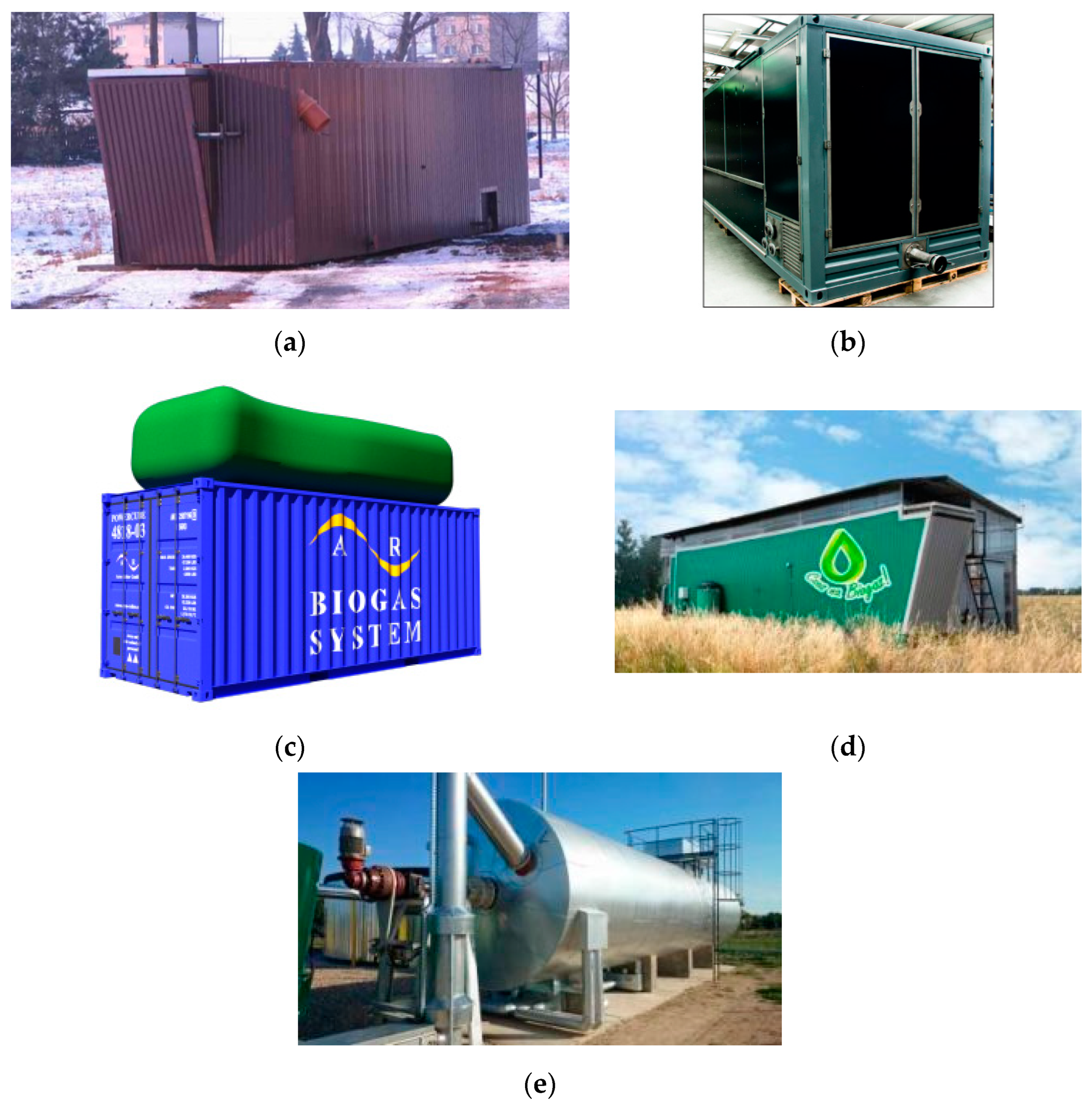
The main idea behind the creators of the agricultural micro-biogas plant container, version number 7 (KMR 7) (
Figure 1a), was to adapt its structure to the realities of Polish agriculture [
12]. The micro-biogas plant has been adapted to handle residues from agricultural and livestock production, as well as silage from energy crops grown for specific purposes. The expected production volume of biogas with a content of approximately 55% methane (CH
4) in the digester is 0.97∙10
−3 to 13.8∙10
−3 m
3∙s
−1. Corresponding to this amount of biogas, the electrical power of the micro-biogas plant is approximately 7–10 kW
el (reference value). The designed fermentation chamber with insulation and external cover in the form of trapezoidal sheets does not generally exceed the dimensions of a 40-foot elevated shipping container. The total capacity is approx. 70 m
3, and the capacity of the filling with substrates is approx. 60 m
3. A biogas buffer store with a capacity of approximately 15 m
3, covered with a roof made of trapezoidal sheet metal, is planned to be placed on top of the container. The chamber is fed with substrates through a covered injection channel in the upper part of the container. The substrates delivered through the injection channel fall down the inclined plate into the interior of the chamber. The chamber does not have a mixer, and periodic spraying with percolate (fermented slurry) is used. The produced biogas, collected in the biogas buffer storage, is directed to the engine of the cogeneration unit, where the biogas energy is converted into electricity and heat. The cogeneration system is located on the KMR7 service platform, in a separate soundproofed container or in designated rooms of the farm. KMR7 is equipped with a standard connection system to the low-voltage network, including a switch, a connection cabinet with control and protection equipment, and the required telemechanics installation (telesignaling and telemeasurements). One of the main advantages of the structure is the possibility of transporting it without the need to obtain special permits, including construction [
12].
It was assumed that in order to meet the demand of investors of pico-installations and biogas micro-installations, the basic element should be an agricultural micro-biogas plant container from the company Mega Sp. z o. o. [
13] (
Figure 1b), retrofitted with devices for initial hydrolysis of the feedstock and with devices used to improve the electrical efficiency of the power generator.
The purpose of the AB Biogas System micro-biogas plant (
Figure 1c) is to feed organic waste to the biological fermentation plant and make the resulting biogas available for further use [
14]. The resulting fermentation residue can be used as a liquid soil improver (e.g., fertilizer). In this case, organic waste in the amount of 1.15∙10
−3–11.57∙10
−3 kg∙s
−1 can be recycled and obtain biogas 1.38∙10
−3 m
3∙s
−1. For logistical reasons, the entire micro-biogas plant is mounted in a 20-foot cargo container. Upon delivery, the gas storage facility is mounted on the roof of the container. Any number of micro-biogas plants that can operate in parallel to each other is possible. The introduction of organic waste takes place using a shredding unit. The shredder is mounted at the front and (like all other controls) accessible by opening the container door. Further feeding of shredded waste into the digestion space takes place automatically using a pumping system. The fermenter is equipped with a heater and a paddle mixer. The heating must be externally powered to maintain a constant temperature in the digester, especially during the colder months. The demand for thermal energy depends on the ambient temperature. The paddle mixer is driven by an electric motor via a flange gear and operates at a constant speed. The engine is controlled via an integrated control. The actual fermentation is fully automatic. The produced biogas is collected in a gas tank (mounted on top of the container and protected against wind). The entire gas system operates at a maximum pressure of 5 mbar and is equipped with mechanical overpressure protection. In case of overpressure, biogas is released into the atmosphere. The quantity and quality of the produced biogas are directly dependent on the type and freshness of the organic waste introduced. The fermentation residue is drained and can be used as a liquid soil improver (e.g., fertilizer). The composition of the digestate is directly dependent on the materials introduced. Optionally, a separation unit can be provided to separate the solid and liquid components of the digestate immediately after disposal [
14].
The most popular model of micro-biogas plants from eGmina, Infrastruktura, Energetyka Sp. z o. o., is MB-30 (
Figure 1d). A micro-biogas plant is ideal for smaller livestock or agricultural farms [
15]. Taking into account the specifications of the micro-biogas plant, the following can be achieved:
- -
Year-round electricity production, i.e., 30 kW;
- -
Year-round heat production, i.e., 40 kW;
- -
The production of high-quality and natural fertilizer with any input of several tons per day (feces, silage, etc.);
- -
A simple and maintenance-free system, with supervision via the Internet.
However, the MB-50 agricultural micro-biogas plant (
Figure 1e) is a larger model for medium-sized farms that are able to supply several tons of input per day, reaching 50 kW of electricity and 70 kW of heat per year [
15].
The cogeneration system (CHP) is one of the methods of obtaining heat and electricity with a wide range of applications regarding the fuels that can be used. A cogeneration system can use gaseous, liquid or even solid fuel in systems based, for example, on the production of steam. Compared to the separate production of heat and electricity, cogeneration saves energy. In advanced systems, the amount of waste heat can be at most 20%. When it comes to sustainable development, one of the fundamental issues is energy efficiency.
Anaerobic digestion (AD) consists of many biochemical reactions during which bacteria decompose the organic matter of any substrate into gases such as methane (CH4), carbon dioxide (CO2), hydrogen (H2), hydrogen sulfide (H2S), etc. This process occurs in the absence of free oxygen. The raw materials that can be processed in AD include a wide range of organic residues, but there are certain requirements that make it useful or not. Co-fermentation of different feedstocks or their pretreatment can improve biogas production by balancing the concentration of different nutrients present in different feedstocks, which are crucial for efficient AD.
The interaction between different types of microorganisms involved in the AD process allows for the degradation of complex biomass polymers reacting at different stages of the process. Different groups of bacteria lead at different stages, and the products of one reaction are used as a substrate for subsequent stages.
During hydrolysis, water and extracellular enzymes break down the structure of compounds such as proteins, cellulose or starch, transforming them into monomers and oligomers such as glucose, fatty acids and amino acids. Hydrolytic bacteria multiply very quickly, and this stage occurs at high speed. However, for lignin-rich feedstocks, the degradation of lignin-based polymers becomes the rate-limiting step. At this point in the AD process, some compounds are already suitable for conversion into biogas, but most components still require further conversion steps. The next stage is acidogenesis, in which the leading bacteria are acid-forming. Hydrolysis products are mainly converted into short-chain volatile fatty acids (VFA), alcohol (ethanol or methanol), glycerol and acetone. During this process, by-products are produced, such as CO2, H2, NH3, alcohols and trace amounts of other compounds. Rapid VFA production, if not properly managed, can lead to accumulation in the AD reactor and digestate toxicity. Acetogenic bacteria are responsible for the next stage, called acetogenesis. In this step, acetate, CO2 and H2 are generated from the products from the previous step and some of the long-chain fatty acids from the first step. In this process, excessive H2 concentration can slow down the AD process, but methanogenic bacteria consume the hydrogen produced. This is an example of the need for cooperation between various types of microorganisms needed for the effectiveness of the AD process, activating at various operational stages. The final stage is called methanogenesis, where methane is produced from all the intermediate products present in the digester. Acetate and hydrogen are converted to CO2 and CH4. This process is strictly anaerobic because the acetophilic and hydrogenophilic bacteria responsible for this reaction cannot survive in the presence of oxygen.
For an efficient AD process, it is crucial to optimize several process conditions because AD bacteria are sensitive to any changes occurring in them. Some critical parameters are temperature, pH, organic loading ratio (OLR), hydraulic retention time (HRT) or carbon-to-nitrogen ratio.
OLR is a parameter that refers to the input rate of organic raw material per unit volume of the digester. It varies depending on the type of substrate used for biogas production and is determined experimentally.
HRT refers to the average time that the raw material remains in the digester. Optimally, the substrates should remain in the digester for a long enough time to allow for the greatest possible breakdown of organic matter into biogas. Another parameter that strongly influences the AD process is the carbon-to-nitrogen ratio in the substrate. Microorganisms use carbon as an energy source, and nitrogen is necessary for their growth and metabolism. A low C/N ratio can lead to overproduction of ammonia, which inhibits the process and thus reduces the efficiency of biogas production. On the other hand, too high a C/N ratio may result in insufficient nitrogen concentration for bacterial metabolism and growth. A very difficult parameter to define is pH because different types of bacteria present in the digester require or prefer different pH for optimal performance. Maintaining the optimal pH for all microorganisms present in the same reactor is a difficult task and even more complicated if the substrate has a different nutrient composition [
16].
Without a doubt, the outstanding leader in terms of biogas production and the number of biogas plants in Europe is Germany, which already had over 10,000 functioning biogas plants in 2020. In Germany, 52,158 GWh of energy was produced annually, and in 2018, almost 13% of renewable electricity was produced from biogas and was mainly used to produce electricity and heat. The German model is based on corn silage as the main substrate for biogas production. There is significant potential for the use of small AD plants fed mainly with slurry; however, plants using energy plants as a substrate have a higher electrical potential [
17].
There are over 600 biogas plants in operation in Great Britain, Switzerland and France [
18,
19,
20]. In the UK, most of the substrate used in biogas plants is sewage due to regulations, and according to these regulations, no more than 50% of the raw materials used can be energy-producing plants. There are also significant limitations regarding the type of installation that can be used to produce biogas and the place where it is produced [
19]. In Switzerland, the substrates are similar, and although the number of operating power plants is similar, the reported energy production was almost 3 times lower [
20] compared to the energy generated in France. In France, for several years now, there has been a strong development of biogas plants on farms and centralized ones, the purpose of which is to recover biogas to produce electricity for self-service. For example, in 2017, 113 out of 240 landfills used biogas. It was found that approximately 47% of the recovered energy is converted into electricity, 43% into heat and almost 10% into biomethane. The raw materials used to produce biogas in France are residues from sewage treatment plants, bio-waste, agricultural and industrial waste and landfills [
18].
In Austria and Sweden, almost 300 biogas plants operated in 2020 [
21,
22]. While in Austria, most of the raw material used consists of manure and organic waste, in Sweden, the focus is on the utilization of sewage sludge, which constitutes almost 50% of the substrate used. Additionally, bio-waste, agricultural and industrial waste and landfills are used [
22]. Comparing the amount of energy produced annually, in Sweden, the production efficiency was 3.4 times higher than in Austria. Austrian regulations require that at least 30% of the substrate used for biogas production be manure in order to obtain the feed-in tariff. If organic waste is used, this tariff may be reduced by 20% [
21].
In 2018, the Netherlands had 250 reported biogas plants. Although this number remained almost the same (252) until 2019, the energy efficiency of this installation was truly impressive. There were only 95 co-substrate installations registered in the report dated 2018, while the annual energy production amounted to 3720.83 GWh/year [
23], which is a number similar to the result achieved by over 600 French biogas plants. Most Dutch digesters use local agricultural and animal waste as raw material for biogas production. Many facilities are technologically adapted to refine biogas into biomethane, which can be used as a substitute for natural gas and can be directly injected into the natural gas network.
In Denmark, the number of biogas plants (which in 2020 was 166) is over 100 fewer than in Sweden and Austria, and the amount of energy produced is very comparable to that achieved by its Scandinavian neighbor and much higher than in Austria. There is a strong initiative to fully utilize digestate from agricultural plants, which is further used as fertilizer for crops. In Denmark, by 2020, the use of no more than 12% of energy crops for the production of biogas as an AD raw material is also limited. The new regulation was intended to further reduce this limit [
24].
There were 116 biogas plants operating in Poland in 2020 [
25], which is a significant increase since 2014 when there were 45 operating installations [
26]. The raw materials used for production are mainly agricultural waste, manure and energy plants. In recent years, there has been a systematic increase in the consumption of waste raw materials used for the production of agricultural biogas. The percentage of substrates such as corn silage, cereals or fruit and vegetables used in Polish biogas plants in 2019 was only 10.6%, which is the lowest result since the beginning of the development of biogas plants in this country. The energy generated this year from biogas plants amounted to 306,396 million m
3.
The lowest number of biogas plants are located in Norway. In this Scandinavian country, there were 46 biogas plants operating in 2020, of which 6 are farm-scale, 13 are modernized to produce transport gas and 2 are connected to the local gas network. About 40% of the extracted gas is used for transport purposes, and the total production in 2019 was 922 GWh. The dominant substrate used for the operation of biogas plants in Norway is sewage sludge and food waste [
27].
The development of the biogas industry in Europe is visible, although the dynamics differ depending on the country. Various models were presented, which are based on different types of raw materials used for biogas production and the proportions of substrates used in co-fermenters. Of course, Germany is the undisputed pioneer in the field of this renewable energy source. However, the effort put into improving energy independence and environmental impact is reflected in the growing number of operating biogas plants in other European countries, which gives hope for rapid progress towards the complete abolition of conventional exploitation of fossil fuels. This work highlights the environmental benefits and aspects of sustainable development of cogeneration systems and the importance of these systems for the use of renewable energy. Pointing to the research gap—regarding the adaptation of a cogenerator to the conditions existing on a farm, which should meet the technical and technological expectations for the process of managing the produced methane worth 80% in agricultural biogas—it was proposed to present the current situation, problems and prospects for the optimization and operation of a biogas cogeneration unit, using the example of an agricultural farm. Using their knowledge and industrial capabilities, the components necessary for optimization were used by Woodward Inc., Woodward Poland, Karl Dungs GmbH & Co. KG, and WOMIX.
The research goal was to adapt the cogenerator to the conditions existing on a farm, which should meet the technical and technological expectations for the process of managing the produced methane with a value of 80% in agricultural biogas. The scope of work included making an attempt to determine the operating conditions of the cogenerator and developing the optimization of a biogas cogeneration unit producing electricity and heat in a micro-installation for the needs of an individual farm. A characteristic farm was selected, which has a substrate necessary in the process of methane fermentation of slurry from pig farming. The analysis involved a cogenerator, which constitutes a potential energy demand from the point of view of Polish energy and agriculture in the context of renewable energy production. What is new is the use of a cogeneration unit, which has been adapted to its functionality, taking into account the assessment of the prospects for optimizing the cogeneration system in the context of the use of renewable energy sources as agricultural biogas. The best method was to attempt to determine the operating conditions of the cogenerator to develop the optimization of a biogas cogeneration unit producing electricity and heat in a micro-installation for the needs of an individual farm. This problem was addressed by the Institute of Technology and Life Sciences, National Research Institute in Falenty, and the University of Life Sciences in Lublin as part of the project (project durability period) BIOGAS & EE financed by the National Center for Research and Development and implemented as part of the BIOSTRATEG 1 program.
2. Materials and Methods
At the Institute of Technology and Life Sciences (National Research Institute, Poznań Branch), an installation system with a power of (3–40) kW was developed. This is a pilot installation (
Figure 2) with an active fermenter capacity of 15 m
3 [
28] located on a farm [
29] with 1100 fattened pigs kept in a slatted system [
30].
The raw biogas production node (
Figure 3) is a system for transporting biogas produced in the fermentation tank together with the equipment, enabling the fermentation process to be carried out, controlled and regulated. The fermentation tank is the main and key element of the installation to achieve max. efficiency of fermentation technology. The fermenter, the cylindrical part of which is located vertically, contains a filling in the form of vertical pipes with a rough surface made of plastic, constituting an adhesive bed. In the upper part of the fermenter, there is a common connector through which fresh substrate in the form of slurry and fermenting mass are supplied. Next to it, there is a biogas outlet connector, which is connected to a pipe via a blower, a biogas drainage valve and a biogas inlet connector with a bubbler. The barbotka is located horizontally near the bottom of the fermenter. Vertical pipes, which increase the active surface for the fermentation bacteria flora, are located inside the heating spiral. The heating spiral is connected to a water pump and a heat exchanger, creating a closed water circuit periodically supplied from the outside. In the lower part of the fermenter, there is an outlet port for the fermenting mass, which is connected via the fermenting mass pump to a common port supplying fresh substrate in the form of slurry and fermenting mass to the fermenter. The outer walls of the fermenter are covered with a layer of thermal insulation. The digester has a safety valve, a main digestate outlet connector connected to the digestate pump and a biogas outlet connector through which biogas is discharged for further use. The fermenter is filled with slurry through a connector, preferably in an automatic cycle, ensuring vertical movement of the bio-ferment fraction through the entire tank. The digestate mixed with slurry also flows periodically through this connector. Part of the biogas contained in the gas space of the fermenter is moved to the bubbler and then travels upwards in the form of bubbles, mixing the suspension. The fermenter operates at a temperature of (35–40) °C. The heating medium is warm water flowing through the heating coil. The digestate is drained (2–3) times a day through the main digestate outlet port. When emptying, the fermenter is not filled. Then, the digester is filled with slurry in the same volume as the digestate was removed. The filling level of the fermenter is controlled in an automatic cycle. During filling, the pressure equalizes after the biogas spontaneously flows through the outlet port to the next part of the installation.
Cogeneration node: Technically, this node is a set of a cogenerator, heat exchanger and heat transport system to the operating conditions of the installation. The cogeneration system consists of the following node elements:
- -
Cogenerator;
- -
Elements for installing a cogeneration unit in a biogas plant (installation elements):
Circulation pump for central heating,
Electrically operated valves,
Exhaust gas cooler adapted to a cogeneration engine,
Automatically controlled throttle,
Coolant buffer tank.
- -
A heat exchanger adapted to a multi-fuel generator, which is basically powered by biogas for research purposes; the working medium of the exchanger is water, which will enter the exchanger with max. temp. 38 °C, and the water heated on the exchanger to max. temp. 65 °C; the cogenerator has an exhaust gas cooler with a heat output of 8–10 kW and an exhaust gas temperature of 550 °C;
- -
Heating spiral in the form of a pipe with an internal diameter of dw = 1.25″ = DN32, which is mounted inside the fermenter;
- -
Water pump pumping the heating medium (water) in the system;
- -
Control and control devices: A temperature sensor that indicates the temperature of the water entering the heating spiral and sends a signal to the gate valves; the temperature sensor is helpful in determining the heat balance. Temperature sensors are helpful in determining the temperature distribution in the tank, and a temperature sensor is used to control the operation of the pump;
- -
Air vent is located behind the valve.
The cogeneration node includes the following:
- (1)
Heat transport system—description of the system operation (automatic cycle).
The fermenter’s heating system is designed to maintain the required temperature of the ferment in the process tank. The heating medium at a specified temperature of 65 °C flows between the heat exchanger and the heating spiral in the fermenter until the specified substrate temperature t = (35–40) °C is reached—this is important due to maintaining the heat balance to keep microorganisms alive. Then, when this temperature is exceeded, the sensor sends a signal to the pump control element and turns it off. The temperature of the heating liquid should not exceed 65 °C; it is controlled by a temperature sensor which, when this value is exceeded, sends a signal to the controller on the valves. The temperature of water taken from the exchanger’s exhaust gas chamber should not exceed 95 °C—the value of this temperature is controlled by the temperature sensor, and, if necessary, it will send a control signal disconnecting the flow of exhaust gases through the exchanger, through the gate valve. The heating system should only operate when the fermenter is filled.
- (2)
Power distribution system.
The cogeneration system is equipped with an inverter that synchronizes the frequency of the produced electricity with the power grid. During operation of the generator, energy is fed into the network via a power socket. In the event of a failure and disconnection of the generator or farm from the power grid, the engine will turn off and stop generating electricity.
The tests were carried out on a two-cylinder diesel engine (
Table 1) intended to drive a power generator, which was not designed to burn gaseous fuels. The engine modifications introduced by placing two gas injectors in the intake manifold allowed the engine to also be powered by biogas. Such actions correspond to the situation when an entity producing biogas (biogas plant) attempts to use the obtained biogas on its own to produce electricity using a power generator. In this type of activity, taking into account the economic aspect, the enterprise (biogas plant) usually purchases a diesel engine (higher efficiency than spark ignition engines) or modifies the existing one and adapts it to its own needs without interfering with the system regulating the engine’s operation. In most cases, these are older generation engines/drive units, usually controlled by a mechanical speed controller.
The experimental engine used an electronic control system for the biogas injection system fed to the intake manifold, which, depending on the assumed biogas share and engine operating parameters, regulated the injector opening time. Changing the biogas injector opening time resulted in automatic correction of the liquid fuel dose by the injection pump regulator.
The methodology of the work is to develop an optimization to improve the operational functionality of a biogas cogeneration unit generating electricity and heat in a micro-installation, with a view to ensuring its use for the needs of an individual farm.
3. Results and Discussion
The research biogas installation implemented by the Institute of Technology and Life Sciences in Falenty, Poznań Branch, generates electricity for the needs of an individual farm and thermal energy to heat the fermentation tank in the installation. The combined production of electricity and heat takes place in a cogeneration unit burning biogas produced in a research biogas installation in the process of methane fermentation of slurry from pig farms.
3.1. Experimental Biogas Diesel Engine—Tests
The measurements performed were preliminary tests, the aim of which was to ensure no interference in the systems regulating the operation of the engine driving the generator. It should be emphasized that in the studies of many actors [
32,
33,
34,
35,
36], the total amount of nitrogen oxides (NO
x) was examined regardless of the fuels and combustion systems tested. However, the work carried out measurements of the two most dangerous nitrogen oxides, which often occur together, i.e., NO and NO
2, of which nitrogen dioxide (NO
2) is considered the most dangerous due to its impact on the health of humans and other living organisms. Raw biogas (BG) was used as the reference fuel for the tests. The assessment of the impact of the amount of biogas on the level of CO, NO, NO
2 and particulate matter (PM) emissions was carried out at a constant engine speed for various load levels; the percentage of biogas was changed from 40 to approximately 70–80%, i.e., until significant knocking combustion was detected in the tested engines. The biogas for testing was taken directly from the production installation and injected using a compressor into a cylinder under a pressure of 100 bar, from which a sample was taken for analysis. The composition of BG was determined using a GA2000 gas composition analyzer (
Table 2), and the density and calorific value were calculated based on the biogas composition, the molar mass of the methane and carbon dioxide mixture and the calorific value of methane (
Table 3).
The test stand consisted of a two-cylinder diesel engine with a pre-chamber, 9 kW, liquid-cooled (
Figure 4). The engine is equipped with a fuel supply system with indirect injection with a sectional injection pump. The engine is permanently connected via a PTO (power take-off) shaft to an asynchronous motor controlled by an automatic control and measurement system. The electricity generated by the asynchronous motor was directed directly to the power grid. The experimental station constitutes a compact whole and is used for simulation tests [
31].
The tested combustion engine operated at a constant rotational speed of 2000 rpm ± 30 rpm, which was regulated by the injection pump settings and adjusted using the injection pump regulator depending on the engine load generated by the asynchronous engine control and measurement system. The tests began after warming up the engine so that the engine oil temperature exceeded 70 °C. The measurement was performed at six measurement points for which the torque load value was 0, 4.5, 8, 12, 16 and 20 Nm. After each change of parameter configuration, the engine operated for 0.5 h to stabilize the operating parameters. The operating parameters of the measurement system that were recorded automatically were gas fuel consumption and the composition, temperature and flow level of exhaust gases. The tested gas fuel was introduced into the engine at an ambient temperature of 20 ± 2 °C while maintaining air parameters, i.e., humidity of 46 ± 10% and a pressure of 995 hPa ± 2 hPa.
The share of gases, i.e., NO, NO
2, PM and CO, was measured quantitatively in relation to the mass of exhaust gases. Some simplification has been introduced to express mass exhaust emissions. The exhaust gas was a model of an ideal gas and consisted of a mixture of oxygen, nitrogen and dioxide, excluding traces of other gases. The Clapeyron Equation (1) was used to determine the mass amount of gases:
where
V* denotes the exhaust gases flow m
3 in normal conditions per hour [m
3·h
−1],
p denotes the pressure in the exhaust manifold [Pa],
T denotes exhaust gases temperature [K], and
R denotes the universal gas constant [J·kg
−1·K
−1].
The quantitative exhaust gas stream was converted into a mass based on the molar mass of the O
2, N
2 and CO
2 gas mixture. The proportion of gases was measured using an exhaust gas analyzer, except for nitrogen. Relative to the exhaust gas mass, the mass flow
x for NO, NO
2, PM and CO was calculated according to Formula (2):
where
M denotes the molar mass of the
i-th gas [kg·kmol
−1];
y denotes the quantitative share of the
i-th gas [-];
B denotes the share of
x-th gas (CO, NO, NO
2) in the exhaust [mg·kg
−1]; and
i denotes O
2, CO
2 and N
2.
As the share of BG in the engine fuel increases, the amount of carbon oxides increases significantly. This is caused by a change in the engine power supply parameters while operating parameters remain unchanged. Changing the injection angle can reduce CO emissions, but only slightly compared to engine emissions. The place and method of BG injection, i.e., injection into the intake manifold, are also important. The use of multi-point or even direct injection could significantly reduce CO emissions.
The presence of BG supplying the engine significantly reduces NOx. However, if we analyze NO and NO
2 emissions separately, we can see a clear increase in the emissions of toxic NO
2 particles. It follows that the presence of BG has a negative impact on the qualitative and quantitative composition of nitrogen oxides emitted in exhaust gases [
31].
3.2. Operation of a Biogas Cogeneration Unit
The experience gathered by Professor Wałowski’s research team confirmed the effectiveness of biogas production while also demonstrating certain technical limitations and difficulties in operating the research installation by an individual farm. This issue concerns the production of electricity and heat in micro-installations for the individual needs of an agricultural and breeding farm that is a prosumer in accordance with the Act on Renewable Energy Sources (RES).
The existing control and monitoring system for the operation of the cogeneration unit (
Figure 5) does not meet the amended requirements of the Distribution Network Operation and Operation Instructions (IRiESD) of national distribution network operators (DSOs), including the IRiESD applicable at ENEA Operator, i.e., the DSO responsible for the recipients in Ocieszyn [
38].
It does not ensure automatic synchronization (data confirmed by the manufacturer) of the cogeneration unit with the public network but only allows the unit to operate in island mode on a separate energy network of the biogas plant with variable rotational speed (i.e., with variable frequency of the generated electricity) and has serious difficulties in synchronization with the public network via using an existing frequency converter.
It does not have automatic protections required by the IRiESD of national DSO, usually defined as tg φ = 0.4 (power factor required by the DSO).
It does not ensure operation with the power factor required by the territorially appropriate DSO.
As a result, the existing control and control system for the operation of the cogeneration unit prevents the most effective mode of operation of the research installation as a prosumer micro-installation in accordance with the Act on RES along with the “storage” of temporary surpluses of electricity in the network.
The internally inconsistent control system, consisting of many systems and modules, requires constant supervision by the operator, and at the same time, its complicated operation still causes many errors and alarms.
It practically excludes the autonomous operation of a cogeneration unit without constant supervision by the end user, i.e., an individual farm.
It makes it impossible to remotely monitor the operation of the biogas cogeneration unit.
It enables the local archiving of parameters and operating states of the cogeneration unit, which is very useful for the end user.
A high-pressure biogas supply system for the cogeneration unit engine (typical for vehicles powered by compressed natural gas (CNG) (up to a pressure of 20–25 MPa) used to drive motor vehicles, but not for stationary devices) requires feeding the unit with high-pressure biogas, causing significant operational difficulties.
A high-pressure reducer with low durability and expensive regeneration additionally requires heating with fluid from the combustion engine cooling system.
The necessity to use energy-intensive biogas compressors feeding the unit.
Compressing biogas and storing it in cylinders poses additional risks and the need for high-pressure cylinders to be supervised by the Office of Technical Inspection (UDT).
The simplified mixer for preparing the air–gas mixture creates significant difficulties in starting and subsequent unstable operation of the cogeneration unit with changing parameters of the biogas produced in the installation.
The installation for receiving thermal energy (produced by the cogeneration unit) does not ensure the possibility of long-term operation of the cogeneration unit in the summer season in the absence of demand for thermal energy.
Too much consumption of electricity and heat generated for the installation’s own needs unnecessarily reduces its energy efficiency:
- -
High electricity consumption by the variable speed control system of the cogeneration unit and the operation control systems of the biogas plant;
- -
Large losses of electrical energy through the frequency converter;
- -
Large losses of thermal energy through the heating system with direct heat collection from cooling the engine of the cogeneration unit without a plate exchanger;
- -
Large losses of electricity due to the need to power biogas compressors;
- -
Thermal energy losses from cooling the engine of the cogeneration unit when heating the reducer expand the biogas in the unit.
The existing control and control system for the operation of the cogeneration unit, its biogas supply system and the system for receiving the produced thermal energy significantly reduce the energy efficiency of the research installation while also indicating directions for optimizing the cogeneration unit before proceeding to the implementation phase of a research micro-biogas plant on an individual farm.
Before continuous operation of the cogeneration unit (AG20P—
Figure 6) powered by biogas from a research agricultural biogas plant, the necessary works were carried out, which included the following:
- -
Installation of an AVR Marelli Mark V regulator in the generator set, adapted to work in parallel with the network and cooperate with the easYgen 2500 controller;
- -
Connection of the generator with the generator’s electrical cabinet and connection of the generator’s electrical cabinet with the biogas plant’s electrical installation; installation of a test orifice for the engine’s air intake on the generator’s air filter; checking the correctness of the connection of the exhaust gas outlet from the generator to the biogas plant’s exhaust gas cooling system and the facility’s chimney installation;
- -
Installation of a biogas pressure transducer at the inlet to the pipe connecting the biogas plant with the unit and increasing the volume and pressure of the biogas cushion in the fermentation tank.
Calibration of the AG20P generator at idle speed consisted of programming the settings of the Woodward easYgen 2500 controller, updating the controller software and tuning the Woodward easYgen 2500 controller of the generator and the AVR Marelli Mark V controller of the generator. Synchronization of the generator with the network (as agreed upon by the ENEA Operator Power Station in Oborniki) and initial calibration of the operation took place under load in parallel mode with the network. Preparation of the unit for parallel operation with the network with an active load of 10 kW and test work were carried out until the biogas in the fermentation tank was exhausted.
As a result of the commissioning and operational operation of the AG20P cogeneration unit in a research agricultural biogas plant, it was confirmed that the unit operated correctly when powered by biogas produced during the fermentation of slurry from an agricultural farm. The operational start-up, synchronization and operation of the AG20P biogas unit in parallel mode with the ENEA Operator network were correct when powered by biogas with typical parameters of a biogas plant (methane content ≥ 60%, biogas pressure at the unit connection ≥ 2 kPa). When the AG20P biogas unit operated in parallel with the grid with an active power of up to 11.7 kW, the electricity produced by the unit met the adopted assumptions and requirements:
- -
It was fully used (without the supply of surpluses to the ENEA Operator network) by the agricultural farm where the research biogas plant is installed (the electricity meter on the farm did not show the supply of surpluses to the ENEA Operator network);
- -
The voltage values applicable to the ENEA Operator were not exceeded.
As a result of the commissioning and operational operation of the AG20P cogeneration unit in the agricultural research biogas plant, it is recommended to make additional changes to enable better adaptation of the research biogas plant to operation on an agricultural farm:
- -
Installation of an automatic start and synchronization button for the AG20P unit on the automation cabinet door (the controller has already been programmed to operate the above-mentioned button), simplifying the operation of the unit by farm personnel;
- -
Making and connecting the pin connection system (which will be delivered by Woodward Poland) of the lambda probe heating harness (the controller has already been programmed to operate the above-mentioned button) allows for better control of the air–gas mixture composition by the AFR system in the unit;
- -
Woodward Poland configured the AFR throttle of the unit to work with the Woodward lambda probe P/N 1689-1249 (transducer LSF 4.2, Bosch heated exhaust gas, oxygen, 460 MM);
- -
Installation of the target engine air intake flange on the unit’s air filter;
- -
Moving the biogas pressure gauge to the Dungs cut-off solenoid valve;
- -
Woodward Poland provides a table of protections and their programmed settings, as well as a certificate confirming that the programmed Woodward easYgen 2500 controller meets the requirements:
- (a)
NC RfG Network Code (including General Application Requirements according to URE decision no. DRE.7128.550.2.2018.ZJ);
- (b)
ENEA Operator set of requirements for type A energy generation modules (including micro-installations);
- -
Allowing for formal notification to the ENEA Operator of a micro-installation in Ocieszyn with the AG20P unit as a generation source/energy generation module;
- -
Installation of a biogas buffer tank, allowing for the extension of the daily operating cycle of the unit at a biogas pressure at the unit connection ≥ 2 kPa;
- -
Regeneration of desulphurizers enabling the unit to be powered by biogas that meets the purity requirements (including the permissible content of sulfur and H2S in the biogas and the permissible moisture content of the biogas);
- -
Providing an Internet connection to the Woodward easYgen 2500 controller of the unit, allowing remote access to the controller for Woodward Poland (remote adjustment of settings, remote diagnostics).
3.3. Optimization of a Biogas Cogeneration Unit
During the optimization in accordance with
Table 4, the existing biogas cogeneration unit was thoroughly reconfigured.
The existing ineffective components of the control and monitoring system of the cogeneration unit and the high-pressure biogas supply system of the cogeneration unit engine were replaced with appropriately selected modern, high-efficiency components, which will also ensure the required improvement in functionality.
An advanced Woodward easYgen 2500 controller was installed (providing automatic synchronization of the cogeneration unit with the public network), which will take over control of the operation of the cogeneration unit and eliminate the need to use a frequency converter (the previous simple easYgen 1000 controller for island operation was dismantled).
As a result of using a control system with automatic synchronization of the cogeneration unit with the public grid, it will not be necessary to use a frequency converter.
A low-pressure biogas engine supply system was installed (biogas filter, double shut-off solenoid valve and zero-pressure regulator). The existing high-pressure biogas engine supply system with a “car” high-pressure reducer and its heating system with engine coolant were dismantled.
A low-pressure engine gas installation was installed (a modern throttle integrated with a mixer and an electronic actuator—an actuator in the engine speed control system, which, based on the control signal from the engine controller, determines the angular position of the throttle flap). However, the existing “car” high-pressure mixer with a throttle and actuator was dismantled. As a result of dismantling the high-pressure biogas supply system of the engine, it will not be necessary to use energy-consuming biogas compressors and biogas pressure cylinders requiring UDT supervision.
For the existing components of the air–gas mixture control system (appropriately selected for the biogas plant), the generator engine controller and components of the installation for receiving thermal energy from the running engine were installed:
- -
Integrated throttle with electronic mixture actuator;
- -
Engine controller module operating in a closed loop (with the possibility of operating in an open loop) with an integrated absolute pressure and temperature sensor in the engine intake manifold;
- -
High-efficiency plate heat exchanger (with thermal insulation);
- -
Three-way valve switching the flow of engine coolant (exchanger–emergency cooler).
In the next stage of optimization (during the ongoing implementation of the unit on an individual farm), the latest types of components were also installed (exhaust thermocouple, main controller, ignition system controller) and installation and launch of software for remote monitoring of the operation of the biogas cogeneration unit and local archiving of parameters and operating states of the cogeneration unit by the end user, i.e., by an individual farm.
Using their knowledge and industrial capabilities, the components necessary for optimization were used by Woodward Inc. (Fort Collins, CO, USA), Woodward Poland (Niepołomice, Poland), Karl Dungs GmbH & Co. KG (Urbach, Germany), and WOMIX (Szubin, Poland).
Woodward Poland (part of the global concern Woodward, Inc.), a manufacturer of automation systems (including advanced controllers, dampers with electronic actuators, mixers and engine controllers) for gas power and cogeneration units, has made the following available for testing:
- -
easYgen 2500 unit controller (with the possibility of later replacing it with the more advanced easYgen 2800 controller, which is currently in the certification phase), along with installation and commissioning at the biogas plant;
- -
PG+ gas engine controller with built-in SECM70 module along with cables, plugs and sensors;
- -
Integrated L-series throttle with electronic actuator, mixer and mixture controller.
Karl Dungs GmbH & Co. KG, a manufacturer of high-quality gas fittings (including filters, reducers, zero-pressure regulators and integrated solenoid valves with leakage control systems), made available for testing:
- -
GF 510/1 biogas filter;
- -
Double solenoid valve DMV-D 507/11 12VDC (including two connection flanges and an electric plug);
- -
FRNG 508 zero pressure regulator.
WOMIX is a Polish manufacturer and distributor of energy-saving heating fittings for central heating and domestic hot water (including mixing valves with actuators, complete pump group systems and automation of heating installations). They have made the following available for testing:
- -
SWEP B12MTx70 plate heat exchanger;
- -
Thermal insulation of the SWEP EPP/HVAC plate exchanger.
3.4. Operational Functionality of Micro-Installations
Improving the operational functionality as a result of optimizing the biogas cogeneration unit eliminates significant technical limitations and difficulties in operating the research installation by an individual farm and improves its energy efficiency [
39].
Automatic synchronization of the cogeneration unit (
Figure 7) with the public network and operation as a prosumer micro-installation in accordance with the Act on RES demonstrates the “storage” of temporary surpluses of electricity in the network. Before optimization, the control system of the cogeneration unit only enabled its operation in island mode on a separate energy network of the biogas plant with variable rotational speed (i.e., frequency of the generated electricity) and possible synchronization with the public network using a troublesome frequency converter. Moreover, such a mode of cooperation with the network is not permitted by the IRiESD of national DSO for recipients with micro-installations generating electricity, including the ENEA Operator, which is responsible for recipients in Ocieszyn.
Optimization of the biogas cogeneration unit using the advanced Woodward controller of the easYgen 2500/easYgen 2800 series (made available for testing, installed and commissioned by Woodward Poland) enables automatic synchronization of the cogeneration unit with the public network (with the power factor required by the OSD usually as tgφ = 0.4) ENEA Operator and operation of the biogas installation as a prosumer micro-installation in accordance with the Act on RES of 20 February 2015 (Journal of Laws of 2015, item 478 as amended).
In addition to eliminating the need to use a troublesome frequency converter and the parameters of cooperation of the cogeneration unit with the network of national with the IRiESD, the optimization made enables the use of all benefits for an individual farm as a prosumer in accordance with the Act on RES. This includes, among other benefits, ensuring the “storage” of temporary surpluses of electricity in the network and their collection during periods of increased demand for electricity on the farm:
- -
For micro-installations with an electrical power of up to 10 kW, 80% of the surplus electricity supplied to the network can be downloaded free of charge (including the costs of electricity distribution) during the period of increased demand for electricity on the farm;
- -
For micro-installations with an electrical power of up to 50 kW, 70% of the surplus electricity supplied to the network can be downloaded free of charge (including the costs of electricity distribution) during the period of increased demand for electricity on the farm.
For the research biogas installation in Ocieszyn with a cogeneration unit with a maximum electrical power of approx. 16 kWe, due to the current average daily biogas production capacity of the fermentation tank and the average daily demand of the farm for electrical power of approx. 4–6 kW, the appropriate setting is registration as a micro-installation with an active electrical power of 9.9 kW in parallel operation with the public network.
There is no need to compress biogas to power the cogeneration unit. Simplified high-pressure biogas supply system for a cogeneration unit engine (with a high-pressure reducer typical for applications in non-stationary engines—with low durability and expensive regeneration, additionally requiring heating with fluid from the combustion engine cooling system—i.e., for vehicles powered by compressed gas natural CNG) before optimization, required powering the unit with high-pressure biogas and the need to use energy-intensive biogas compressors feeding the unit. The biogas was compressed (and stored in cylinders), creating additional threats, only to be expanded in a reducer at the entrance of the generator to a pressure of approximately 1 bar, feeding a simplified mixer for preparing the air–gas mixture to power the engine of the cogeneration unit.
Optimization of the biogas supply system for the cogeneration unit engine using a low-pressure power supply system (including a zero-pressure reducer and a low-voltage cut-off solenoid valve available for testing) allows the cogeneration unit engine to be powered with biogas at a low pressure of at least 20 mbar (i.e., 2 kPa), which prevails at the outlet of the fermentation tank of the biogas plant. As a result, after optimization, the need to use the following in the biogas plant was eliminated:
- -
Energy-consuming biogas compressors feeding the unit;
- -
Cylinders supervised by the Office of Technical Inspection;
- -
Heating the high-pressure reducer.
Increasing the energy efficiency of a micro-installation by reducing its own needs for the generated electricity. The energy system of the research biogas plant before the optimization of the cogeneration unit is characterized by the significant demand of the biogas plant for the electricity generated by the cogeneration unit:
- -
High electricity consumption before optimization by the variable speed control system of the cogeneration unit and the biogas plant operation control systems;
- -
Large losses of electrical energy through the frequency converter;
- -
Large losses of thermal energy before optimization by the heating system with direct heat collection from cooling the engine of the cogeneration unit without a plate exchanger;
- -
Large losses of electrical energy before optimization by biogas compressors and losses of thermal energy from cooling the engine of the cogeneration unit when heating the reducer and expanding the biogas in the unit.
Optimization of a biogas cogeneration unit using an advanced Woodward controller of the easYgen 2500/easYgen 2800 series with automatic synchronization of the cogeneration unit with the ENEA Operator public network (eliminating the need to use an energy-intensive frequency converter and a serious loss of efficiency when the cogeneration unit engine operates at variable speed rotation) allows for a significant reduction in the biogas plant’s own demand for electricity generated by the cogeneration unit.
Optimization of the biogas supply system of the cogeneration unit engine using a low-pressure system (with a zero-pressure reducer and a low-voltage cut-off solenoid valve) instead of the high-pressure system used before optimization allows for the elimination of the need to use energy-intensive compressors of biogas supplying the unit and to heat the reducer expanding the biogas in the unit, thus resulting in a significant reduction in the biogas plant’s own demand for electricity generated by the cogeneration unit and thermal energy losses from the cogeneration unit engine when heating the reducer.
Optimization of the heating system of a cogeneration unit using a separation plate heat exchanger (provided for testing by the manufacturer of heating equipment WOMIX) allows for avoiding heat energy losses from the unit engine caused before optimization by the heating system with direct heat collection from cooling the engine of the cogeneration unit without an exchanger plate-wise.
The above-described significant reduction in the biogas plant’s own demand for electricity generated by the cogeneration unit and the reduction of heat energy losses from the cogeneration unit engine makes it possible to significantly improve the energy efficiency of the research biogas plant:
- -
Increase the amount of electricity supplied to an individual farm;
- -
Increase the amount of thermal energy supplied in the winter and transitional seasons to heat the fermentation tank, increasing the efficiency of biogas production and, as a result, increasing the power of the cogeneration unit powered by it.
Possibility of long-term operation of the cogeneration unit in the summer season with no demand for heat energy. Heating installation of a research biogas plant before optimization in the summer season with a significant reduction in the demand for thermal energy from the fermentation tank required a troublesome change of settings to ensure continuous cooling of the cogeneration unit engine.
After optimization, the fan cooler system, separation plate heat exchanger and three-way control ball valve built into the cogeneration unit ensure easy switching of the unit between operation in the winter and transitional season (with full heat reception to heat the fermentation tank) and the summer season (significant reduction or no demand for thermal energy by the fermentation tank) and its continuous long-term operation regardless of the season.
Possibility of operation of the cogeneration unit with changing parameters of the produced biogas. The simplified high-pressure biogas supply system for the cogeneration unit engine before optimization was very sensitive to changes in the CH4 content in the biogas produced in the fermentation tank, causing disturbances in the operation of the unit, unstable operation or even the inability to work regardless of attempts to change the settings by user.
Optimization of the biogas cogeneration unit using an advanced Woodward controller of the easYgen 2500/easYgen 2800 series and a throttle integrated with an electronic actuator and a mixer and regulation of the air–gas mixture composition (also made available for testing by Woodward Poland) allows for the stable operation of the cogeneration unit after a change in CH4 content in the biogas produced in the fermentation tank.
An advanced Woodward controller of the easYgen 2500/easYgen 2800 series with a throttle integrated with an electronic actuator and a mixer and regulation of the air–gas mixture composition after additional use of a gas engine operation controller with a built-in Woodward PG+ module (also made available for testing by Woodward Poland) operating in a closed loop ensures autonomous regulation of the air–gas mixture composition and continuity of operation of the cogeneration unit, regardless of fluctuations in the CH4 content in the biogas produced in the fermentation tank without requiring any adjustments to the settings by the user.
The Woodward easYgen 2500/easYgen 2800 series controller system, together with a throttle integrated with an electronic actuator and mixer, regulation of the air–gas mixture composition and a gas engine operation controller with a built-in Woodward PG+ module also ensures safe automatic stopping of the cogeneration unit after the biogas pressure drops below the one set by the user pressure without requiring any intervention by the user.
Possibility of remote monitoring of the operation of a biogas cogeneration unit. The advanced Woodward easYgen 2500/easYgen 2800 series controller and gas engine operation controller with a built-in Woodward PG+ module, after the additional use of an RS-485/LAN interface and a bridge, enable remote monitoring and visualization of the cogeneration unit’s operating parameters on a selected PC computer (together with software) in the local LAN/WiFi network of an individual farm and/or via a secured Internet connection.
Autonomous operation of the cogeneration unit without constant user supervision. Before optimization, the control system of the research biogas plant and its heating installation and biogas supply installation was characterized by the need for constant supervision of the operating biogas plant and the introduction of adjustments to parameter settings, causing significant difficulties for the individual farm as a user.
The optimization concerned a biogas cogeneration unit using the following:
- (a)
Advanced Woodward controller of the easYgen 2500/easYgen 2800 series (with automatic synchronization of the cogeneration unit with the public network);
- (b)
Low-pressure biogas supply system (with a zero-pressure reducer and a low-voltage shut-off solenoid valve);
- (c)
A throttle integrated with an electronic actuator and a mixer and air–gas mixture regulation;
- (d)
Gas engine controller with built-in Woodward PG+ module;
- (e)
Heating system with a separation plate heat exchanger and a 3-way control ball valve;
- (f)
Remote monitoring and visualization of the operating parameters of the cogeneration unit in the local LAN/WiFi network.
Optimization ensured the autonomous operation of the cogeneration unit without constant supervision of adjustments to parameter settings by the individual agricultural and breeding farm as the user.
Local archiving of parameters and operating states of the cogeneration unit. After using the RS-485/LAN interface and bridge, the advanced Woodward easYgen 2500/easYgen 2800 series controller and gas engine operation controller with a built-in Woodward PG+ module enable local archiving of parameters and operating states of the cogeneration unit on a selected PC computer (including software) and/or NAS server in the local LAN/WiFi network of an individual farm; the demand for thermal energy from the fermentation tank required a troublesome change of settings to ensure continuous cooling of the cogeneration unit engine.
3.5. The Topicality of the Problem and the Scope of Possible Solutions
Biogas is a renewable fuel with favorable properties and parameters, enabling its wide use in virtually every economic area. Biogas is a fuel produced locally, most often from raw materials obtained nearby, and is an energy carrier that leaves a relatively small carbon footprint [
28].
The agricultural industry’s interest in small-scale biogas production allowed design companies to develop a prosumer concept for mobile installations, often with a simple container structure, ready to be placed in the economic infrastructure. Designing a specific micro-biogas plant is basically carried out individually for each farm. The biogas plants implemented so far are characterized by great diversity—both in terms of the equipment installed, the amount of biogas produced and the energy obtained from it.
The main idea of the circular economy is to separate economic growth from resource consumption and environmental impact. The characteristic circular economy approach assumes minimization of the amount of waste generated at the project level and normally includes innovations throughout the entire value chain. Adequate waste management is essential not only to ensure healthy living conditions but also to mitigate climate change. Accordingly, the research on developing strategies to boost the circularity of waste management systems is ongoing. In this context, two waste streams are concurrently managed to recover energy and materials in the present study. Specifically, real leachate collected from a full-scale mature landfill site was preliminarily treated through active filtration to remove inhibitory substances partially and then tested, at the laboratory scale, as a nutrient solution for semi-continuous anaerobic digestion of a carbonaceous substrate represented by market waste. The results demonstrate that, at an organic loading rate of 1.0 gVS∙L
−1∙d
−1, the process was impossible without using the nutrient solution, while the nitrogen present in the pretreated leachate could balance the carbon content of the market waste and provide the system with the necessary buffering capacity, ensuring process stability. The average methane yield (approximately 0.29 NL∙gVS
−1) was satisfactory and consistent with the literature. Despite the increases in both the organic loading rate (up to 1.5 gVS∙L
−1∙d
−1) and volume of added pretreated leachate (up to 100% of the dilution medium), the process remained stable with a slightly lower methane yield of 0.21 NL∙gVS
−1, thanks to nitrogen supplementation. The potential use of produced methane as a renewable energy source and residual digestate as fertilizer would close the loop of managing these waste streams [
40].
From an agricultural point of view, agricultural biogas plants are particularly important because they enable the management of all waste biomass and its conversion into useful energy and agricultural fertilizer. Target group, i.e., a group with access to the substrate (pig slurry) and possibly problems with its disposal for an optimal amount of livestock of 1100–2400 piglets or fattening pigs for one farm. Of course, the technology can be adapted to an inventory of less than 1100 piglets or pigs for one farm.
The required technical and technological criteria for the production and processing of biogas were indicated. An example of pilot production of biogas for mesophilic fermentation using pig slurry is presented. The technology and a pilot installation adapted to a farm were presented. The course of changes in the volume flow of biogas for the average daily production of agricultural biogas and the qualitative composition of agricultural biogas produced from pig slurry indicated 80% CH4.
In this research, direct measurements were taken, and for this purpose, instruments for measuring gas flow, pressure (pressure difference) and temperature were used. These instruments were properly calibrated, which resulted in the relation to the gas flow meters used, which are given in
Table 5.
The analysis of the measurement error was also a subject of our consideration. It was found that with respect to the measured values, this analysis did not bring any significant improvement to the estimation of the measurement error. In this regard, the detailed description of the measurement error analysis was omitted.
By way of an example, the algorithm for calculating the error and the uncertainty of air volume flow measurement, which results from the analysis of measurement errors, is presented. The calculation results according to the algorithm are presented in
Table 6.
As can be seen from
Table 6, the expected (average) value for the adopted measurement is 3.74 × 10
−4 m
3∙s
−1, and at the result (at the confidence level 0.99), it is 3.74 × 10
−4 ± 3.29 × 10
−5 m
3∙s
−1, which gives an average measurement error for the analyzed series of 8.7%. The average relative mistake for the entire scope of the flow of gas amounted to ±5.3%.
Also noteworthy are publications pointing to the thermodynamic model of the microbial hydrolysis process [
41], proposed biological strategies that can be divided into three groups, i.e., “upstream”, “mainstream” and “downstream” approaches [
42], and techniques for biological removal of pollutants from biogas [
43]. Certainly, future research will focus on sustainability features when assessing bioenergy and bioproduct systems [
44].

 ,
, 


