Article

Development and Investigation of the Hysteretic Behavior of an X-Shaped Metal Damper with an Oblique Angle

1
Architects & Engineers Co., Ltd. of Southeast University, Nanjing 210096, China
2
School of Civil Engineering, Henan University of Technology, Zhengzhou 450001, China
3
School of Civil Engineering, Southeast University, Nanjing 211189, China
4
School of Urban Construction, Hubei Business College, Wuhan 430079, China
*
Author to whom correspondence should be addressed.
Appl. Sci. 2023, 13(22), 12464; https://doi.org/10.3390/app132212464
Submission received: 9 October 2023 / Revised: 3 November 2023 / Accepted: 6 November 2023 / Published: 17 November 2023

Abstract

:
To investigate the hysteretic behavior of an X-shaped metal damper (XMD) with an oblique angle, cyclic loading tests were carried out on nine specimens, including two XMDs without buckling-restrained devices, four XMDs with stiffening ribs, and three XMDs with cover plates as references. The test results showed that the oblique angle could effectively increase the stiffness, strength, and energy dissipation of the XMD. When the oblique angle of an XMD with stiffening ribs increased from 0° to 30° at the applied displacement of 8.4 mm, the mean strengths and cumulative energy dissipation of specimens increased by about 80.77% and 80.57%, respectively. Although asymmetric hysteretic loops were also observed in specimens with an oblique angle and buckling-restrained devices, stable hysteretic curves were obtained. This indicated that the stiffening ribs and cover plates can effectively constrain the buckling behavior of XMDs. Additionally, the mean strengths of specimens with stiffening ribs were a little higher than those of specimens with cover plates. Subsequently, the finite element analysis models of the XMDs were proposed, in which the metal plasticity model considering isotropic and kinematical hardening was used to model the material properties of steel, and the simulation results matched well with the test results. Finally, the theoretical calculation method was proposed to predict the elastic stiffness of specimens, and the theoretical elastic stiffness matched well with the test results.

1. Introduction

With the continuous development of construction technology and construction methods, the traditional reinforced concrete (RC) frame–shear wall structure system has gradually controlled building collapse and personnel casualties. However, the economic losses and social impacts caused by earthquakes are still significant [1,2]. Therefore, a precast RC structure with the goal of achieving rapid functional recovery after earthquakes may become a key technology in the field of seismic engineering [3,4].
To meet the functional requirements of buildings and structural seismic resistance requirements, precast RC frame–shear wall structural systems are commonly used in schools, office buildings, hotels, and medical facilities [5]. As the main lateral force-resisting component for the precast RC frame–shear wall structure, the shear wall has a significant effect on the seismic responses for this structural system. At present, the concept based on equivalent cast-in-place is often adopted in the design of a precast shear wall, which features the same seismic performance as the traditional shear wall that can be found in the precast shear wall with wet joints.
Sleeve grouting connections [6], pore-forming grouted connections [7], post-pouring belt connections [8], etc., are the main wet joints, which have the disadvantages of more wet work, difficulty in positioning steel bars, and quality assurance for construction. In addition, shear walls are difficult to repair and reinforce after earthquakes due to the higher stress concentration. The above problems can be found in the 2010 Chile earthquake [9], 2011 New Zealand Christchurch earthquake [10], and 2023 Turkey earthquake [11]. However, in New Zealand, the Southern Cross Hospital Endoscopy Building was subject to the design concept of resilient structures after being damaged slightly, and those structures meant the building remained in working order after the 2011 Christchurch earthquake [12].
Among the efforts to improve the repairability of a shear wall, the vertical seams of the shear wall connected by dampers have been proven as an effective method. In comparison to the traditional shear wall, the flexural failure mode has been an improvement and now constitutes the main failure mode for this shear wall system because the dampers can serve as the first seismic fortification line for protecting the shear wall.
According to the energy-dissipating principle, the dampers adopted in engineering structures are mainly divided into metal dampers, friction dampers [13], and viscoelastic dampers [14,15,16]. Additionally, metal dampers with the benefits of low cost, convenience to obtain, and excellent energy dissipation are the most widely used, which can be divided into flexural-yield-type, shear-yield-type, and tension-yield-type metal dampers. Owing to the simple design and excellent energy-dissipating capacity of the ADAS [17] and U-shaped dampers [18], the flexural-yield-type metal dampers [19,20,21,22,23] developed lately are mostly derivatives of the aforementioned dampers and are often designed with new metal materials [24]. These have mainly been successfully applied in the frame structure [19,20], shear wall structure [21,22], self-centering concrete wall structure [23], and base-isolated structure [24,25] to improve the seismic resilience of a structure. Although the stable energy dissipation can be found in the flexural-yield-type metal dampers, the stiffness and bearing capacity of this metal damper are relatively lower considering the obvious out-of-plane deformation behavior. Compared with the flexural-type metal dampers, the shear-type metal dampers have higher stiffness and bearing capacity due to in-plane deformation behavior. To effectively make full use of the steel materials, the yield energy dissipation segment of steel plates is often induced directionally by means of a weakening section, resulting in the development of an X-shaped metal damper [25,26,27,28,29,30,31]. X-shaped metal dampers were used in combination with the stiffening ribs to restrict the out-of-plane deformation of steel plates, such as the channel-like section steel in precast steel–concrete frame structures [27,28], shape-optimized composite metallic yielding dampers in frame-bracing structures [29], steel panel dampers in precast rocking wall structures [30], etc. For the tension–yield-type metal damper, round steel has been successfully used in the wall toe of the unbonded post-tensioned precast concrete walls [30,32]. Similarly, round steel was also used in combination with a circular steel tube to restrict the buckling deformation of the round steel. In addition, the angle steel machined by the shape memory alloy material has been proven to be an effective damper used in the wall toes of shear walls [33].
As expected, the material properties of steel can be fully utilized when the metal dampers are in tension. Based on the above analysis, the metal dampers were often used by weakening the steel section, such as the X-shaped metal damper (XMD), which was mainly used in the energy-dissipating devices in the beam–column joints and additional dampers of frame structures, vertical seams of precast shear wall structures, and self-centering wall structures by utilizing the flexural and shear properties of steel. However, there are few studies on the application of tension–yield-type XMDs in the vertical seams of precast shear walls. When lateral loads were applied on the above shear walls, relative displacement between wall panels could be found in the vertical seams of shear walls, as shown in Figure 1. It can be seen from Figure 1 that the failure mode of a precast shear wall with vertical seams can be changed from a shear failure to flexural–shear or flexural failure mode, resulting in significant improvement of the plastic deformation capacity of the shear wall. If the XMD is designed with an oblique angle, the metal damper will be in tension and shear, and the material properties of steel can be put to full use to better make up for the loss of strength and energy dissipation of a precast shear wall due to the installation of vertical seams. Except for the application of the XMD with an oblique angle on the precast monolithic shear wall [34], the above metal dampers were successfully used on the unbonded post-tensioned concrete wall [35].
In this study, cyclic loading tests were conducted on six specimens to study the effect of the oblique angle on the hysteretic performance of XMDs, and three specimens with cover plates served as the references for assessing the influence of stiffening ribs on the hysteretic performance of XMD. Additionally, an elastic stiffness calculation method for an XMD with an oblique angle was proposed. Finally, finite element analysis models were also proposed for simulating the hysteretic behavior of an XMD.

2. Damper Shape Selection

The rectangular metal damper adopted at the vertical seams of a shear wall can be assumed as a beam with fixed supported ends. The simplified calculation model is shown in Figure 2 for when a unit displacement (Δ) was applied in a rectangular metal damper, in which point O represents the centroid of the rectangular cross-section of the metal damper, l represents the length of the rectangular metal damper, w represents the width of the rectangular metal damper, and the length and width of the rectangular cross-section are defined as the x-axis and y-axis, respectively.
For a rectangular metal damper with flexural deformation, the maximum normal stress (σmax) of a cross-section along the length direction can be obtained based on the following elastic flexural formulas [36], as shown in Equations (1)–(3).
σ max = M ( x ) y max I z
M ( x ) = M z x 0.5 l
I z = 1 12 t h 3 ( x )
where M(x) represents the bending moment at a random position x; Mz represents the maximum bending moment; h(x) represents the cross-section height; ymax represents the position at the edge of the rectangular cross-section and can be expressed by h(x); Iz represents the cross-sectional moment of inertia of the neutral axis Z; and t represents the thickness of the rectangular metal damper.
Based on Equations (1)–(3), the maximum normal stress of the cross-section for the rectangular metal damper can be expressed as follows:
σ max = 24 M z t l x h 2 ( x )
As expected, when the maximum normal stresses of each cross-section are equal and reach yield stress simultaneously, the material properties of steel can fully used for a rectangular metal damper. Therefore, it can be seen from Equation (4) that x / h 2 ( x ) must be a constant value. In other words, h(x) can be expressed as follows:
h ( x ) = c x
where c represents a constant value.
According to the above analysis, the metal dampers can make full use of the steel material properties when metal plates are machined to a parabolic-shaped curve. However, parabolic-shaped curves can be replaced by a straight line due to machining difficulties, forming the X-shaped metal damper, as shown in Figure 1a.

3. Cyclic Loading Tests

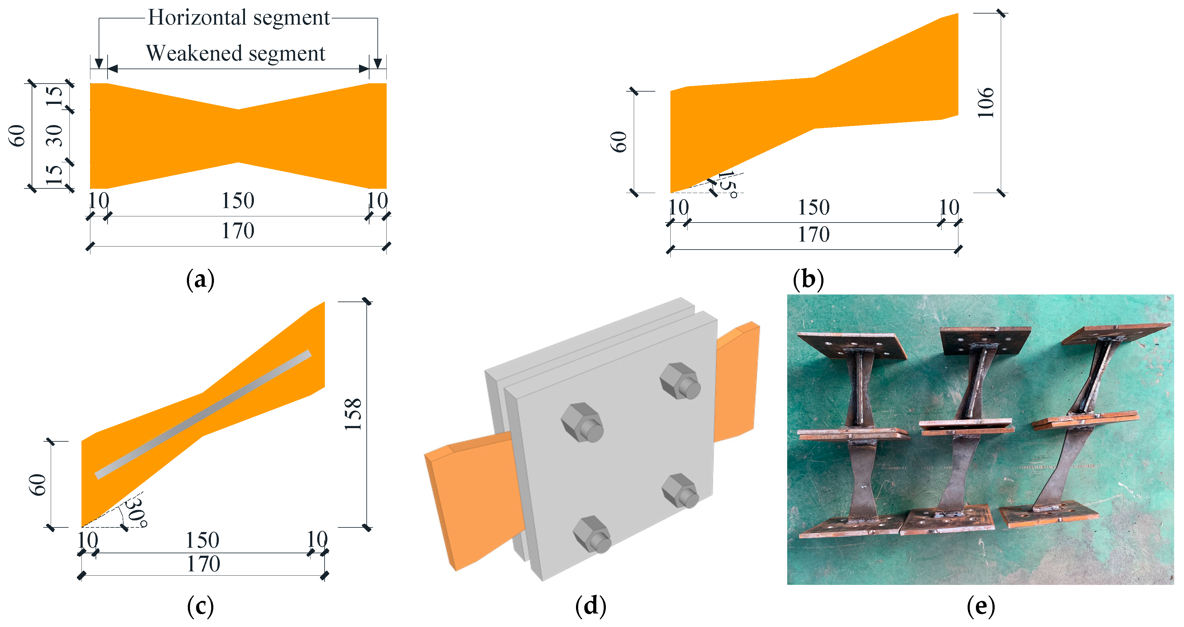
3.1. Specimen Design

Based on the above theoretical analysis results, the oblique angle and buckling-restrained devices were selected as parameters to investigate the hysteretic behavior of an XMD. The design details of the specimens are illustrated in Table 1 and Figure 3. Nine specimens with different parameters were tested while subjected to cyclic loadings. All specimens were machined using a 6 mm thick steel plate and consisted of horizontal and weakened segments, as shown in Figure 3a. The horizontal and weakened segments were 150 mm and 20 mm, respectively. The oblique angle of 15° and 30° were selected as the analysis parameters of our tests. It should be noted that two stiffening ribs with a width of 6 mm, height of 10 mm, and length of 155 mm were welded with steel plates to restrict the buckling behavior. In addition, the XMDs with cover plates were selected as reference specimens for investigating the influence of stiffening ribs on the hysteretic performance of X-shaped steel plates.

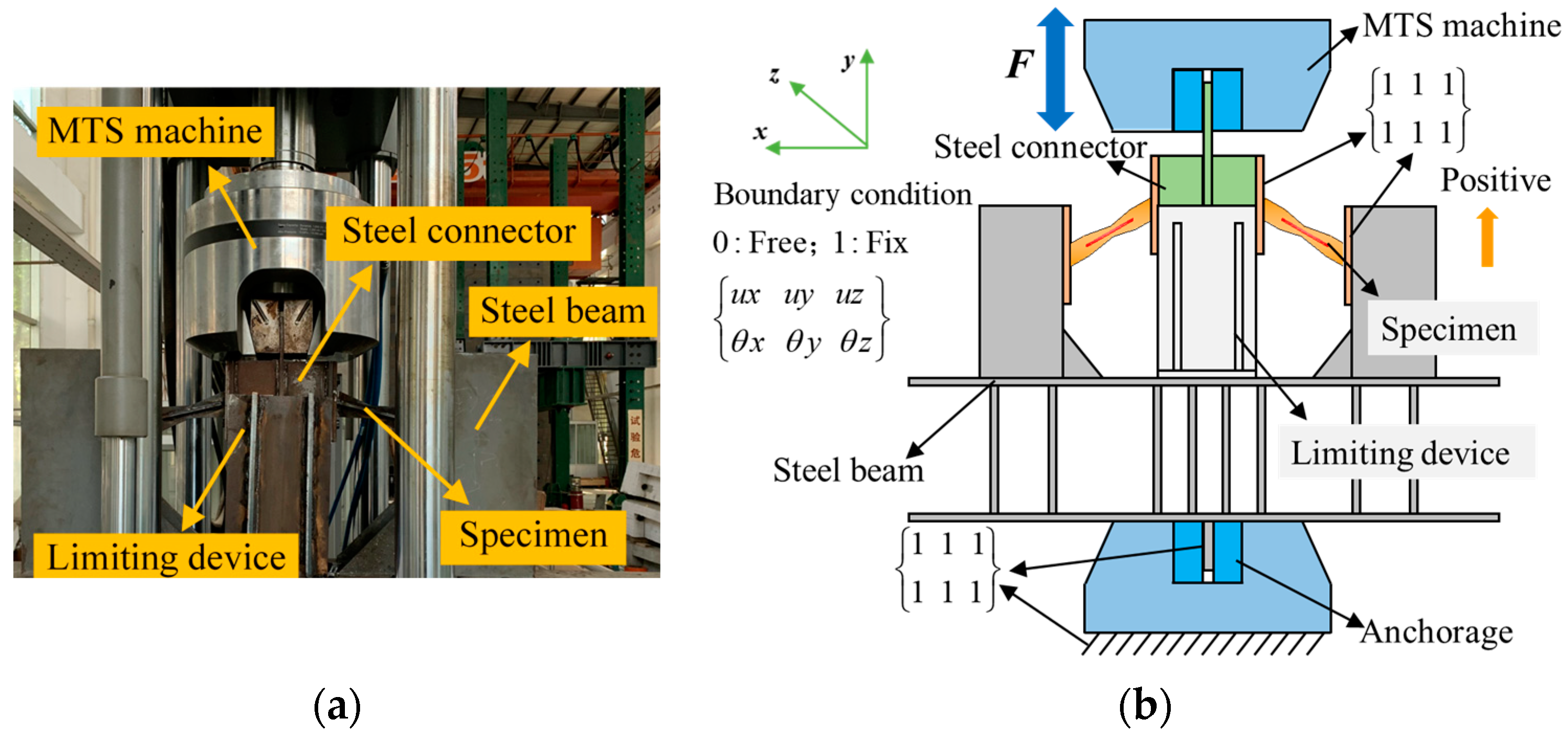
3.2. Test Setup and Procedure

The sketch map and photograph of the test setup for the dampers are illustrated in Figure 4. A 500 kN mechanical testing and simulation (MTS) machine was used to simulate the cyclic loads applied to the tested specimens.
For the convenience of conducting tests and obtaining test data accurately, two specimens with same design details were connected with a special steel beam and steel connector by bolts to test the hysteretic performance of X-shaped metal dampers, as shown in Figure 4. Additionally, the bottom of the special steel beam was anchored with the clamp of the MTS machine to simulate a rigid connection. The special steel beam was anchored with the top clamp of the MTS machine to apply cyclic loads. To reduce the deviation of test results, limiting devices were machined and arranged at the steel beam to constrain the out-of-plane behavior of the MTS machine with a spherical hinge connection.
A displacement-controlled protocol was adopted in the tests, and each applied displacement was equal to the multiples of the yield displacement of the XMDs in accordance with ANSI/AISC 360-16 [37], as shown in Figure 5. Yield displacements could be approximately obtained based on theoretical analysis and numerical analysis, and the initial displacements for all specimens were approximately equal to 0.3 mm.

4. Results and Discussions
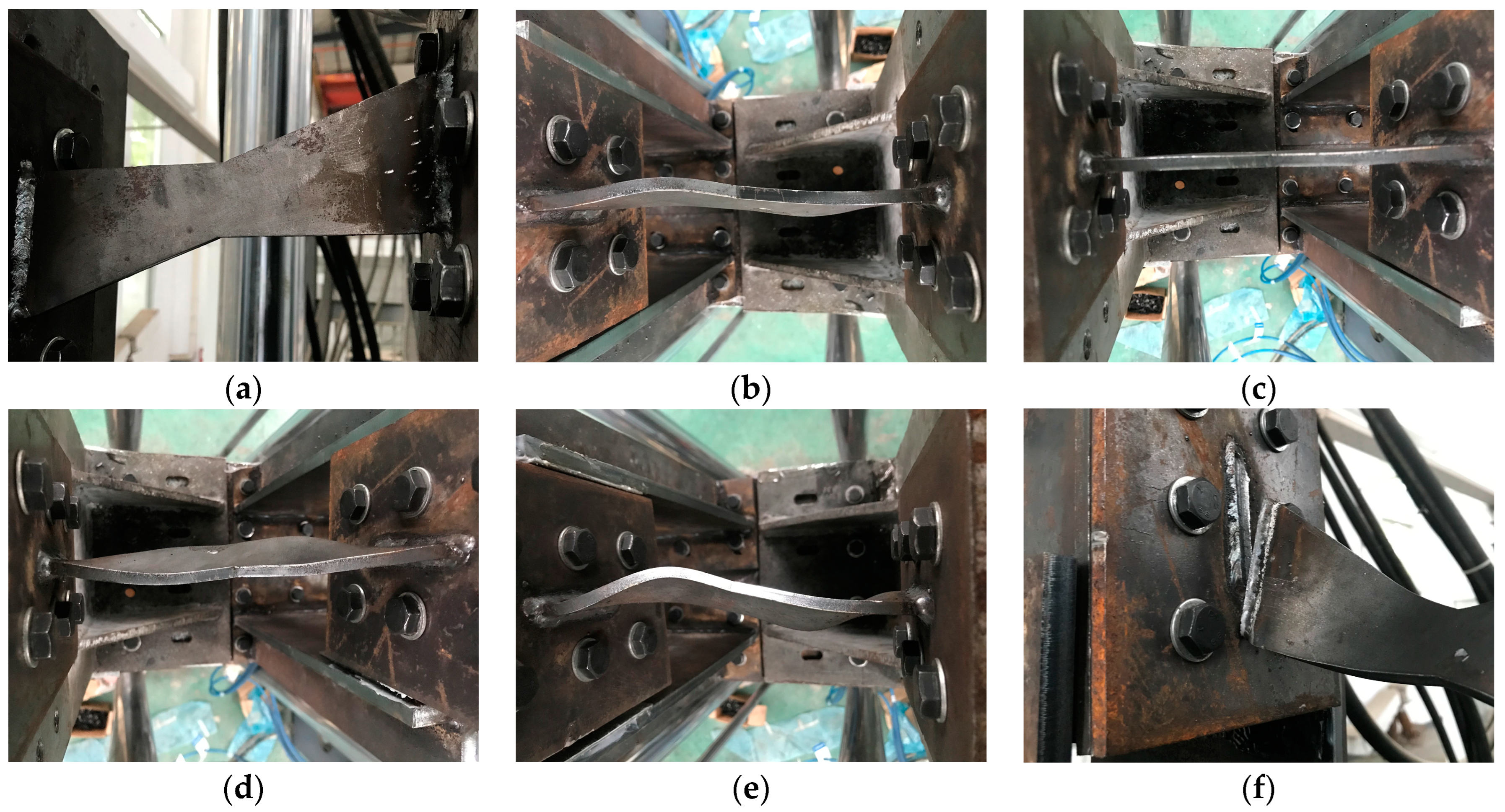
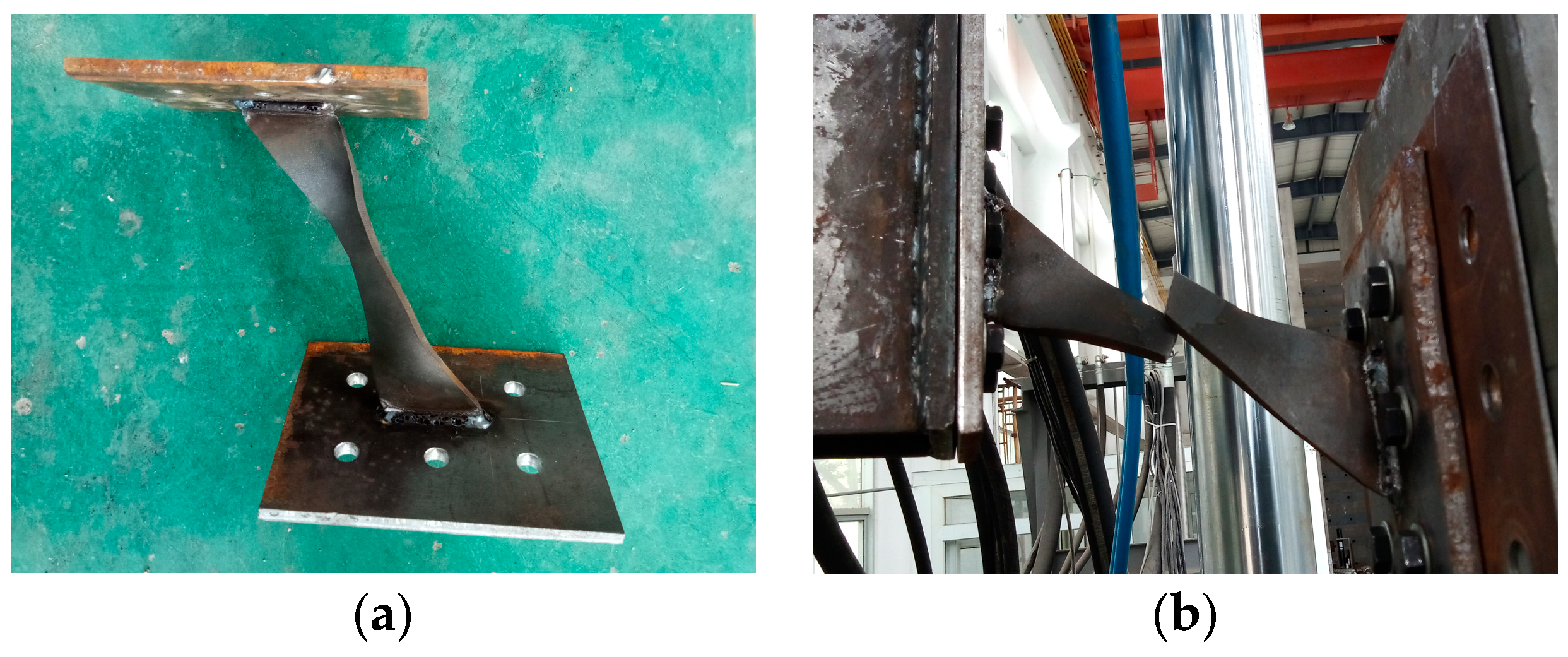
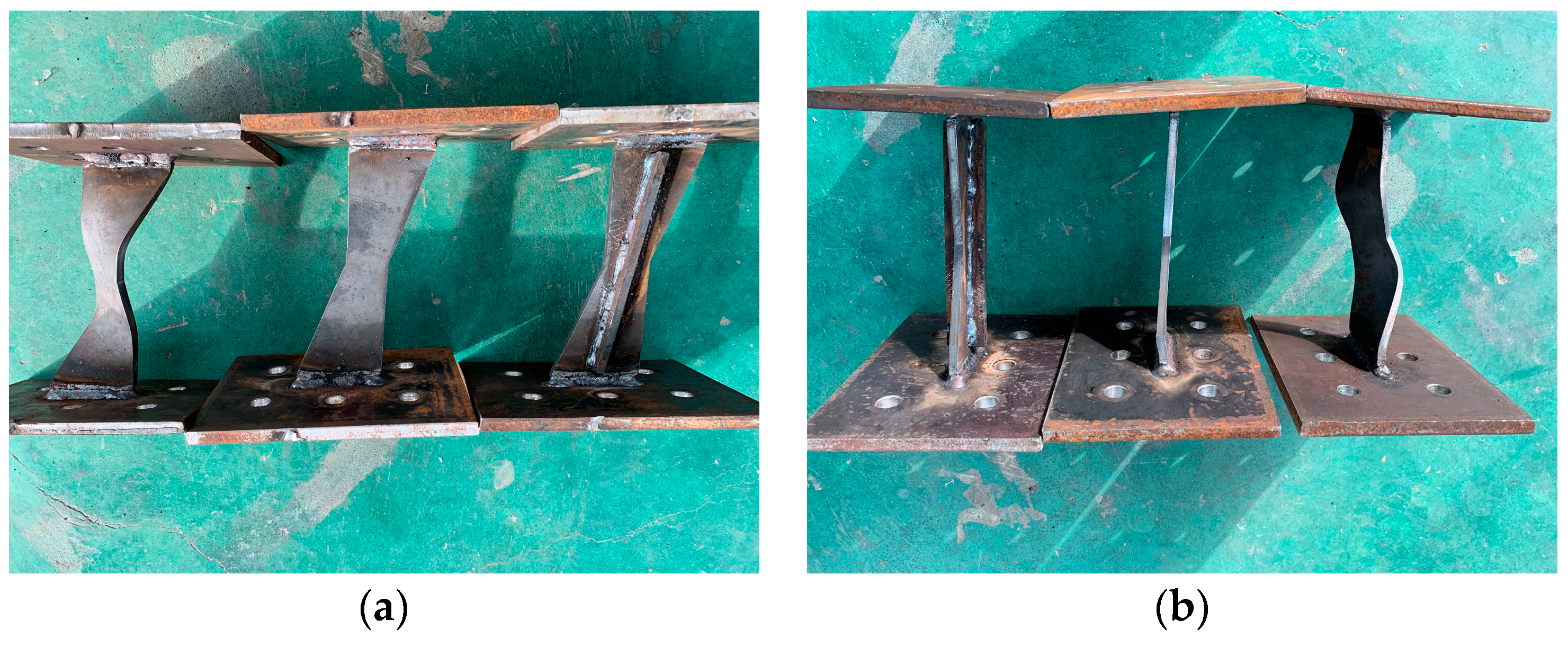
4.1. Failure Modes

For ease of description, the hydraulic actuator pushing the tested specimen is defined as the positive direction, as shown in Figure 4b. Based on the observed phenomena of the test results, two types of deformation characteristics could be found in the tested specimens, that is, out-of-plane buckling deformation and in-plane deformation behaviors. Additionally, a steel plate fracture and weld fracture were the main failure modes of X-shaped metal dampers.
Specimen W30-O15° was taken as an example to analyze the failure processes of X-shaped metal dampers without buckling-restrained devices. Before the applied displacement reached 4.8 mm, the deformation characteristics of specimen W30-O15° were in-plane deformation behavior, as shown in Figure 6a. When the applied displacement was 6.0 mm in the negative direction, the X-shaped metal damper was mainly in compression and shear, resulting in obvious buckling deformation, as shown in Figure 6b. At the applied displacement of 7.2 mm in the positive direction, the buckling deformations of steel plates were eliminated due to the shear and tensile behavior of specimen W30-O15°, as shown in Figure 6c. With an increase in the applied displacement, the out-of-plane and in-plane deformation behaviors of X-shaped metal dampers alternated repeatedly. When the applied displacement was 14.4 mm in the positive direction, the buckling deformation of steel plates could not be recovered, as shown in Figure 6d. In addition, the out-of-plane deformations of steel plates in the negative direction were much larger than those of steel plates in the positive direction, as shown in Figure 6e. Finally, a weld fracture was found in specimen W30-O15° due to enormous buckling deformation, as shown in Figure 6f. For specimen W30-O30°, third-order buckling behavior was also observed in the entire loading process, and a steel fracture at the center of the weakened segment was found in another specimen, as shown in Figure 7.
Specimen W20-O0°-LS was taken as an example to analyze the failure processes of X-shaped metal dampers with stiffening ribs. In the early loading process, there was no out-of-plane deformation or obvious in-plane deformation observed in specimen W20-O0°-LS, as shown in Figure 8a. With the increase in applied displacement, in-plane deformation was gradually observed due to higher shear and tensile force. When the applied displacement reached 10.2 mm, S-shaped deformation behavior could be found in the stiffening ribs, as shown in Figure 8b. When the applied displacement increased continuously, in-plane deformation was obviously seen in the stiffening ribs, as shown in Figure 8c. The welding seams fractured and the test stopped when the applied displacement was 19.2 mm, as shown in Figure 8d. For the other specimens with stiffening ribs, welding fractures were the main failure modes due to higher in-plane stiffness.
Specimens with an oblique angle of 15° were taken as examples to compare the influence of buckling-restrained devices on the hysteretic performance of X-shaped metal dampers. Figure 9 shows the final deformation characteristics of specimens W30-O15°, W30-O15°-LP, and W30-O15°-LS. According to the test results, there was no obvious buckling behavior observed in specimen W30-O15°-LP, indicating that cover plates can effectively restrict the out-of-plane deformation of X-shaped metal dampers. However, because the length of cover plates was smaller than that of the X-shaped steel plates, out-of-plane deformations at the end of X-shaped metal dampers were observed in the late plastic stage. The elastic stiffness of specimens with cover plates would not change in the above situation, but the plastic strengths decreased due to local buckling behavior. Similarly, the main failure modes of specimens with cover plates were welding fractures due to the out-of-plane restrictive effect of cover plates.
Based on the above analysis, it can be concluded that stiffening ribs and cover plates could effectively restrict the buckling deformation of X-shaped steel plates. Compared with cover plates, stiffening ribs with simple design details were more suitable for application in engineering structures.

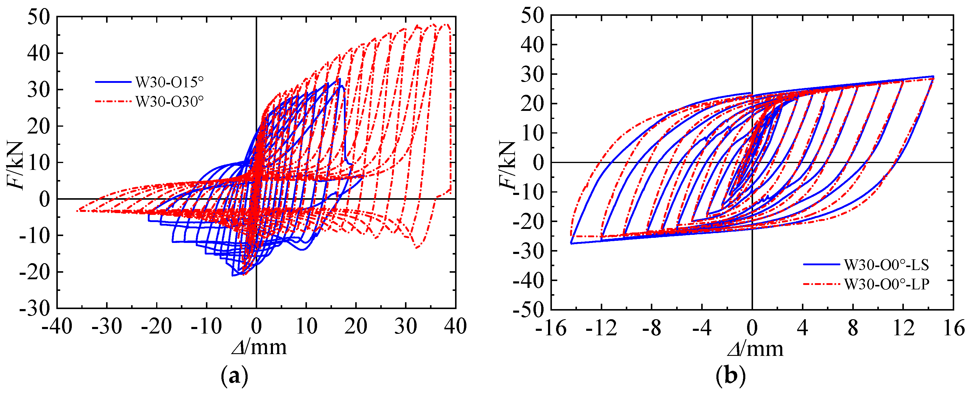
4.2. Hysteretic Behavior

Figure 10 shows the test load–displacement curves of the specimens. It can be seen from Figure 10 that specimens W30-O15° and W30-O30° showed quite different deformation characteristics, which demonstrated that stiffness and strength in the positive direction were significantly larger than those of specimens in the negative direction, indicating the bucking behaviors of specimens W30-O15° and W30-O30° in comparison to other specimens. These were because when the applied loads were in the positive direction, X-shaped metal plates with an oblique angle were mainly in tension and shear, as shown in Figure 4b. In the negative direction, X-shaped metal plates were mainly in compression, resulting in the occurrence of out-of-plane deformation. Subsequently, the tensile and shear behaviors of X-shaped metal plates eliminated the out-of-plane deformation. Therefore, the hysteretic curves of specimens W30-O15° and W30-O30° were obviously asymmetric. Additionally, the above buckling behaviors of specimens W30-O15° and W30-O30° could also be found in the obtained test results, as shown in Figure 7.
In Section 5.1, an elastic stiffness calculation method for X-shaped metal dampers with an oblique angle is proposed. Additionally, Euler’s critical stress for specimens in the negative position can be determined based on the following equation [38]: P cr = π 2 E I ( μ L ) 2 , where Pcr represents the critical buckling load of compressive components, EI represents the elastic stiffness of compressive components, μ represents the length coefficient of compressive components, and L represents the length of compressive components. Therefore, the buckling behavior in the hysteretic curves for specimen W30-O30° was more obvious compared with that of specimen W30-O15° due to lesser Euler’s stress. In addition, when the applied displacement was lower than 3.6 mm, the corresponding loads were lower than the critical buckling load; therefore, parallelogram hysteretic loops were observed in specimens W30-O15° and W30-O30°, as shown in Figure 10a. After that, the hysteretic loops of specimens W30-O15° and W30-O30° showed obvious buckling characteristics.
It can be seen from Figure 10b–e that relatively stable load–displacement curves were obtained in the other specimens, which indicated that cover plates and stiffening ribs can effectively restrict the buckling behavior of X-shaped metal dampers. Asymmetric hysteretic loops were also observed in specimens with an oblique angle of 15° or 30°, as shown in Figure 10c,d. The hysteretic loops of specimens with stiffening ribs were slightly fatter than those of specimens with cover plates due to the contribution of stiffening ribs, as shown in Figure 10b–d. This implied that specimens with stiffening ribs can be used as an energy-dissipating device for shear walls with vertical joints. Additionally, the hysteretic curves of specimens W20-O0°-LS and W30-O0°-LS were asymmetric and specimen W30-O0°-LS showed fatter hysteretic loops, as shown in Figure 10e.

4.3. Skeleton Curves

For the convenience of comparison, for specimens with different parameters, the strength and energy dissipation were selected when the applied displacement was 8.4 mm. The main test results are shown in Table 2, in which Fm represents the mean value of strength for a specimen. The skeleton curves of specimens are illustrated in Figure 11.
Figure 11a shows the force–displacement responses for specimens without buckling-restrained devices. In the negative direction, the strengths of specimens W30-O15° and W30-O30° increased with the increased displacement before the buckling behavior was noted. After that, the strengths decreased rapidly and kept a lower value. The buckling behavior of specimen W30-O30° occurred earlier than that of specimen W30-O15° due to the larger oblique angle. However, the strength of specimen W30-O30° was close to that of specimen W30-O15° in the case of buckling failure. In the positive direction, specimens W30-O15° and W30-O30° showed obvious elastic, elastic–plastic, and plastic behaviors of steel plates. At the applied displacement of 17.4 mm, the strength of specimen W30-O15° was approximately 32.95 kN, which was 16.83% smaller than that of specimen W30-O30°. Additionally, the max strength of specimen W30-O30° reached 47.95 kN.
Figure 11b,c show the force–displacement responses for specimens with different oblique angles. It can be seen that the strength increased with the increase in oblique angles. At the applied displacement of 8.4 mm, the mean strengths of specimens W30-O15°-LS and W30-O30°-LS were approximately 33.62 kN and 45.97 kN, which were 32.21% and 80.77% higher than that of specimen W30-O0°-LS, respectively. For specimens with cover plates, the mean strengths of specimens W30-O15°-LP and W30-O30°-LP were 15.02% and 63.64% higher than that of specimen W30-O0°-LP, respectively. In addition, the mean strengths of specimens W30-O0°-LS, W30-O15°-LS, and W30-O30°-LS were a little higher than those of specimens W30-O0°-LP, W30-O15°-LP, and W30-O30°-LP, respectively. This indicated that stiffening ribs could not only restrict the buckling behavior of X-shaped metal plates but also slightly increase the strengths.
Figure 11d shows the force–displacement responses for specimens with different weakened segment widths. At the applied displacement of 8.4 mm, the mean strength of specimen W20-O0°-LS was approximately 23.25 kN. When the weakened segment width increased from 20 mm to 30 mm, the mean strength of specimen W30-O0°-LS increased by about 9.38% compared with that of specimen W20-O0°-LS.

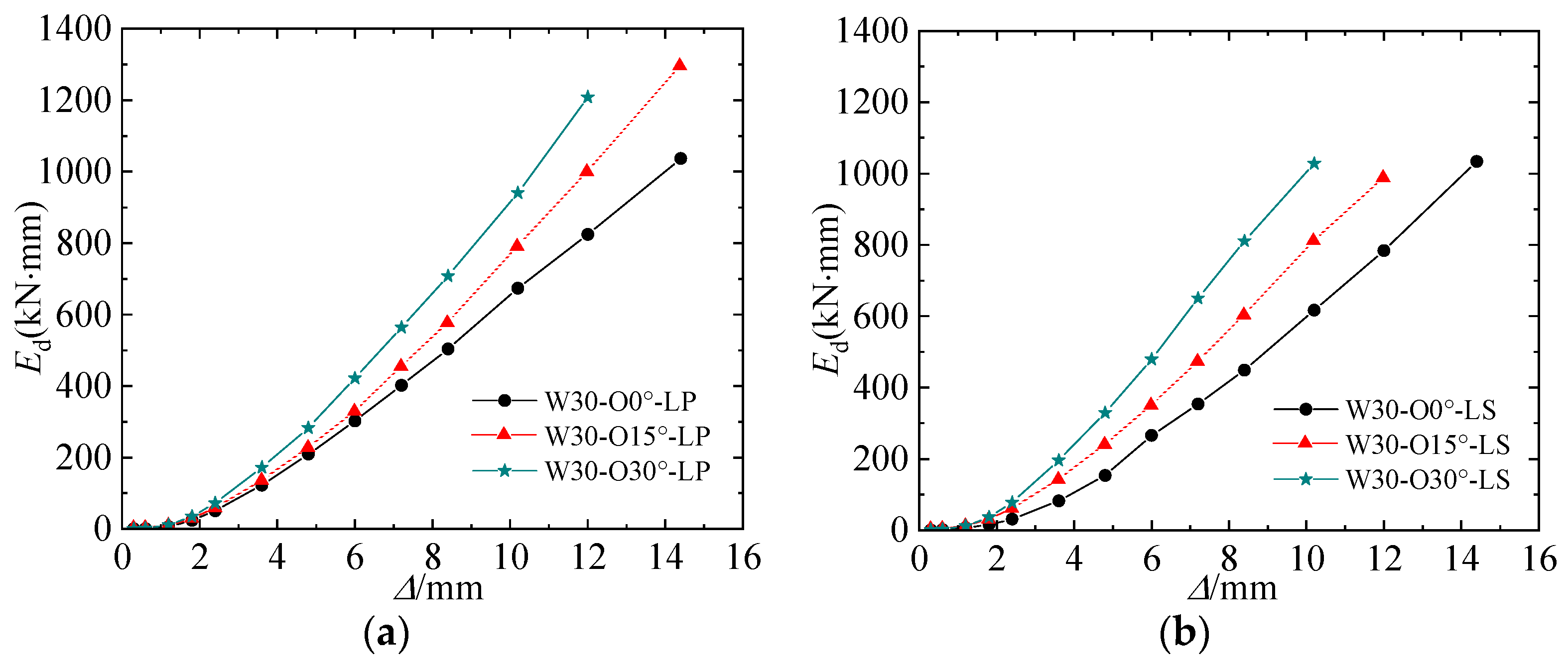
4.4. Energy Dissipation

Cumulative energy dissipation (Ed) and the equivalent viscous damping coefficient(he) are often used to assess the energy dissipating capacity. Ed is defined as the accumulated area under hysteretic curves, and he can be calculated using Equation (6). To comprehensively evaluate the energy dissipation capacity, Ed and he of specimens are calculated and compared.
h e = S ABCD 2 π ( S OBF + S ODE )
where SABCD is the area of ABCD, and SOBF and SODE represent the areas of triangles OBF and ODE, respectively, as shown in Figure 12.
Figure 13 and Figure 14 show Ed and he of each specimen. It can be seen that Ed and he increased with an increase in the applied displacement, indicating the better energy dissipation ability of the XMD. Note that the cumulative energy dissipation of specimens appears as linear growth due to the stable plastic stiffness.
Specimens with cover plates are taken as examples to investigate the influence of oblique angles and weakened segment widths on the energy-dissipating ability of specimens. As shown in Figure 13a and Figure 14a, the Ed of specimens W30-O15°-LP and W30-O30°-LP were 575.71 kN·m and 708.30 kN·m at the applied displacement of 8.4 mm, which were about 14.28% and 40.60% higher than those of specimen W30-O0°-LP, respectively. On the contrary, the equivalent viscous damping coefficients of specimens W30-O15°-LP and W30-O30°-LP were 0.67% and 11.52% lower than those of specimen W30-O0°-LP, respectively.
As shown in Table 2, it can be noted from the test results that stiffening ribs and cover plates can effectively restrict the out-of-plane deformation of X-shaped metal plates. Therefore, the Ed and he of specimens with different buckling-restrained devices were greatly similar. However, there were some certain differences between specimens with stiffening ribs and cover plates due to welding quality.

5. Theoretical Analysis

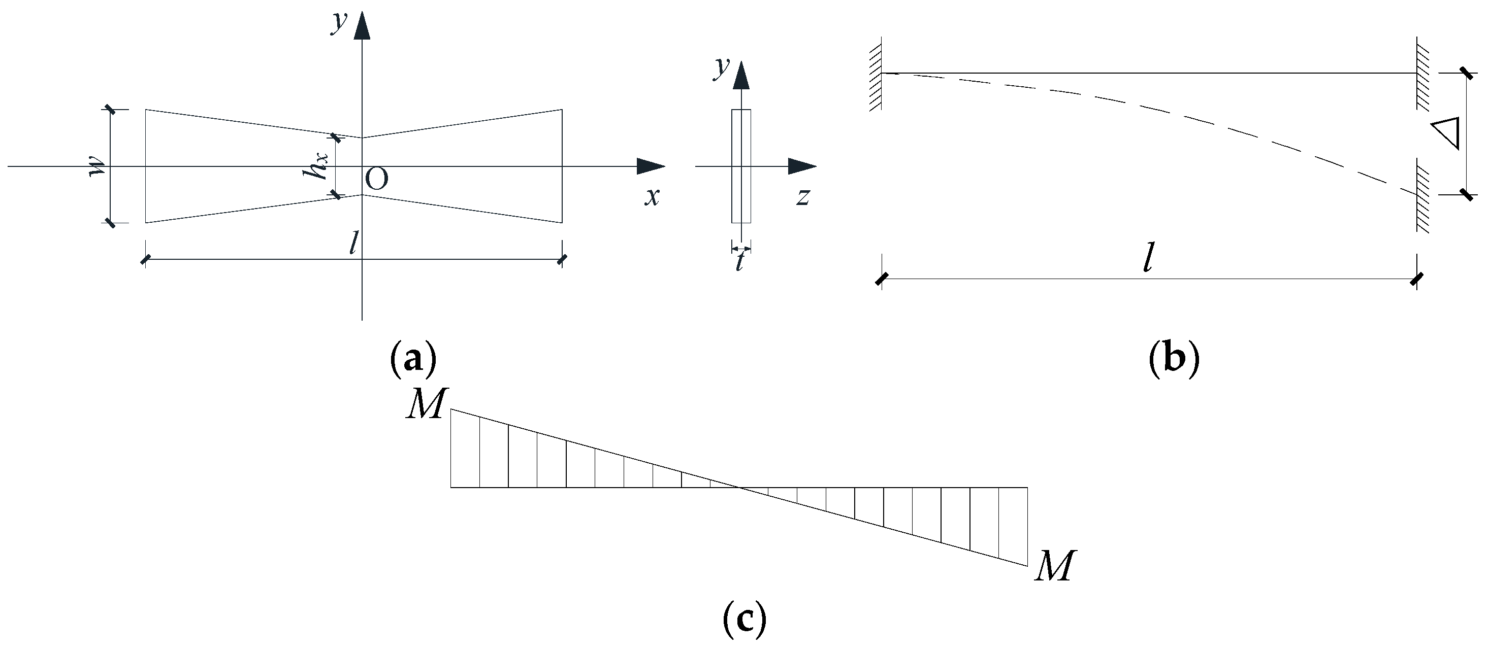
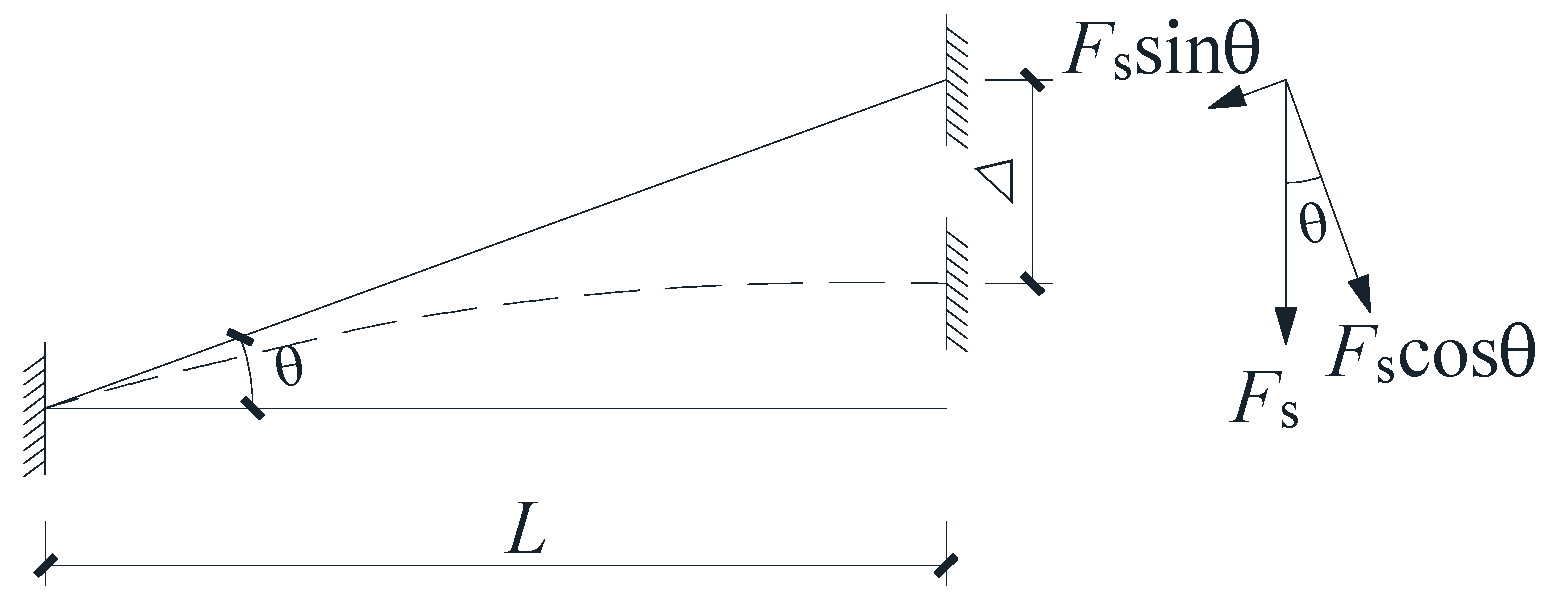
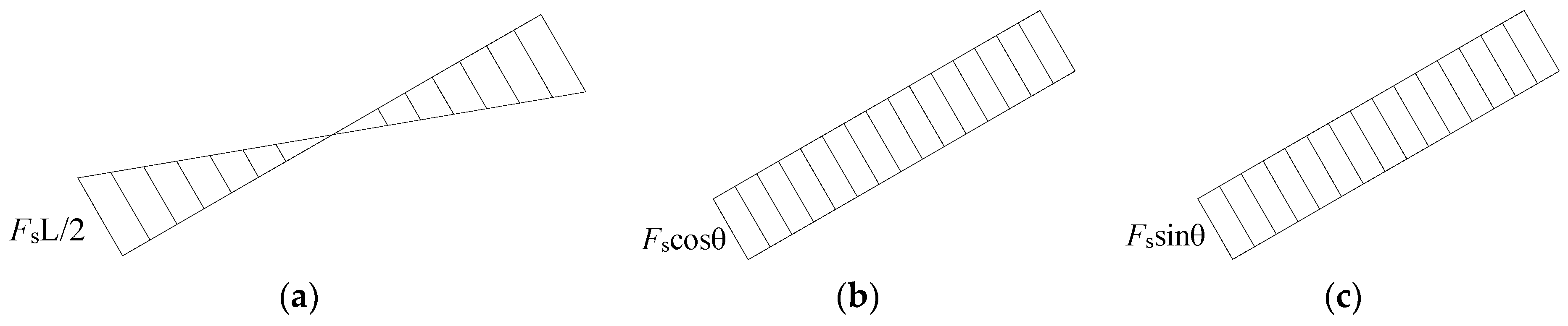
5.1. Elastic Stiffness Calculation Method

The calculating diagram and internal force distribution of an X-shaped metal damper with an oblique angle (θ) are shown in Figure 15 and Figure 16.
When a unit displacement (Δ) was applied at the end of the dampers, the deflection of the dampers was composed of the vertical displacement from the bending moment (ΔM), shear force (ΔV), and axial force (ΔN), which could be obtained according to the graph multiplication method [38]:
Δ M + Δ V + Δ N = Δ
Δ M = M p x ¯ M p x E I eq d x = F s L 3 12 E I eq cos 2 θ
Δ V = f s V p x ¯ V p x G A eq d x = f s F s L cos θ G A eq
Δ N = N p x ¯ N p x E A eq d x = F s L sin 2 θ E A eq cos θ
where Fs represents the shear force; E and G represent the elastic and shear modulus, respectively; M p x , V p x , and N p x represent the bending moment, shear force, and axial force caused by a unit of displacement, respectively; Ieq represents the equivalent moment of inertia of the neutral axis Z; Aeq represents the equivalent cross-section area of the damper; and fs represents the shear deformation coefficient of the section. For a rectangular section, fs is equal to 1.2 [39].
Based on Equations (7)–(10), the unit displacement can be obtained:
F s L 3 12 E I eq cos 2 θ + f s F s L cos θ G A eq + F s L sin 2 θ E A eq cos θ = Δ
Therefore, the elastic stiffness of rectangular metal dampers can be expressed by Equation (12).
K = F s Δ = 12 E G I eq A eq cos 2 θ G A eq L 3 + 12 f s L E I eq cos 3 θ + 12 L G I eq sin 2 θ cos θ
It can be seen that the equivalent moment of inertia and cross-section area need to be calculated to obtain the elastic stiffness of the XMD. In addition, two stiffening ribs were welded with the surface of the X-shaped steel plate to restrict the out-of-plane deformation of dampers. For ease of simplification, X-shaped metal dampers without an oblique angle were selected to calculate the equivalent moment of inertia and cross-section area, which were approximately equal to those of the dampers with an oblique angle. The calculating diagram of an X-shaped metal damper is shown in Figure 17.
In Figure 17, H and h0 represent the maximum and minimum widths of XMD; l0 represents the length of a weakened segment; and a and b represent the width and height of stiffening ribs.
The weakened coefficient was introduced [40] and can be expressed as follows:
λ = ( H h 0 ) l 0
As shown in Figure 17, the cross-section width (h(x)) of dampers at position x can be obtained according to the geometry relation.
h ( x ) = h 0 + 2 λ x ,    0 < x l 0 2 H ,       l 0 2 < x L 2
The length of stiffening ribs was equal to that of the XMD. Therefore, the moment of inertia I(x) at position x was expressed as follows:
I ( x ) = 1 12 t ( h 0 + 2 λ x ) 3 + 2 a b 3 , 0 < x l 0 2 1 12 ( t H 3 + 2 a b 3 ) ,     l 0 2 < x L 2
The cross-sectional area (A(x)) at position x can be also obtained according to the geometry relation.
A ( x ) = t ( h 0 + 2 λ x ) + 2 a b , 0 < x l 0 2 H t + 2 a b ,     l 0 2 < x L 2
Therefore, the equivalent moment of inertia of the neutral axis Z and equivalent cross-sectional area of dampers can be obtained.
I eq = 0 l 0 2 1 12 t ( h 0 + 2 λ x ) 3 + 2 a b 3 d x + l 0 2 L 2 1 12 ( t H 3 + 2 a b 3 ) d x 0.5 L = t l 0 6 L ( h 0 3 2 + 3 λ l 0 h 0 2 4 + λ 2 l 0 2 h 0 2 + λ 3 l 0 3 8 ) + t l 0 12 L ( t H 3 L t H 3 l 0 ) + a b 3 6
A eq = 0 l 0 2 t ( h 0 + 2 λ x ) + 2 a b d x + l 0 2 L 2 ( H t + 2 a b ) d x 0.5 L = t l 0 L ( h 0 + 1 2 λ l 0 ) + H t L ( L l 0 ) + 2 a b
Based on Equation (12) and Equations (17)–(18), the elastic stiffness of X-shaped metal dampers with an oblique angle can be obtained.

5.2. Comparison of Test and Theoretical Results

The theoretical elastic stiffnesses of X-shaped metal dampers according to the proposed method are shown in Table 3, in which Ke and Kt represent the elastic stiffnesses according to experimental and theoretical results for the specimens. The slopes of the skeleton curves at the displacement of 0.3mm were used as the elastic stiffnesses of test specimens. It can be seen from Table 3 that the theoretical elastic stiffness matched well with the tests results. However, due to the gap between specimens and the MTS machine, the theoretical results of specimens W30-O30°-LP, W30-O15°-LS, and W30-O30°-LS were smaller than those of the test results. Additionally, the relative deviation for all specimens was approximately 3%, indicating that the proposed method can effectively predict the elastic stiffness of X-shaped metal dampers with an oblique angle.

6. The Finite Element Analysis of Specimens
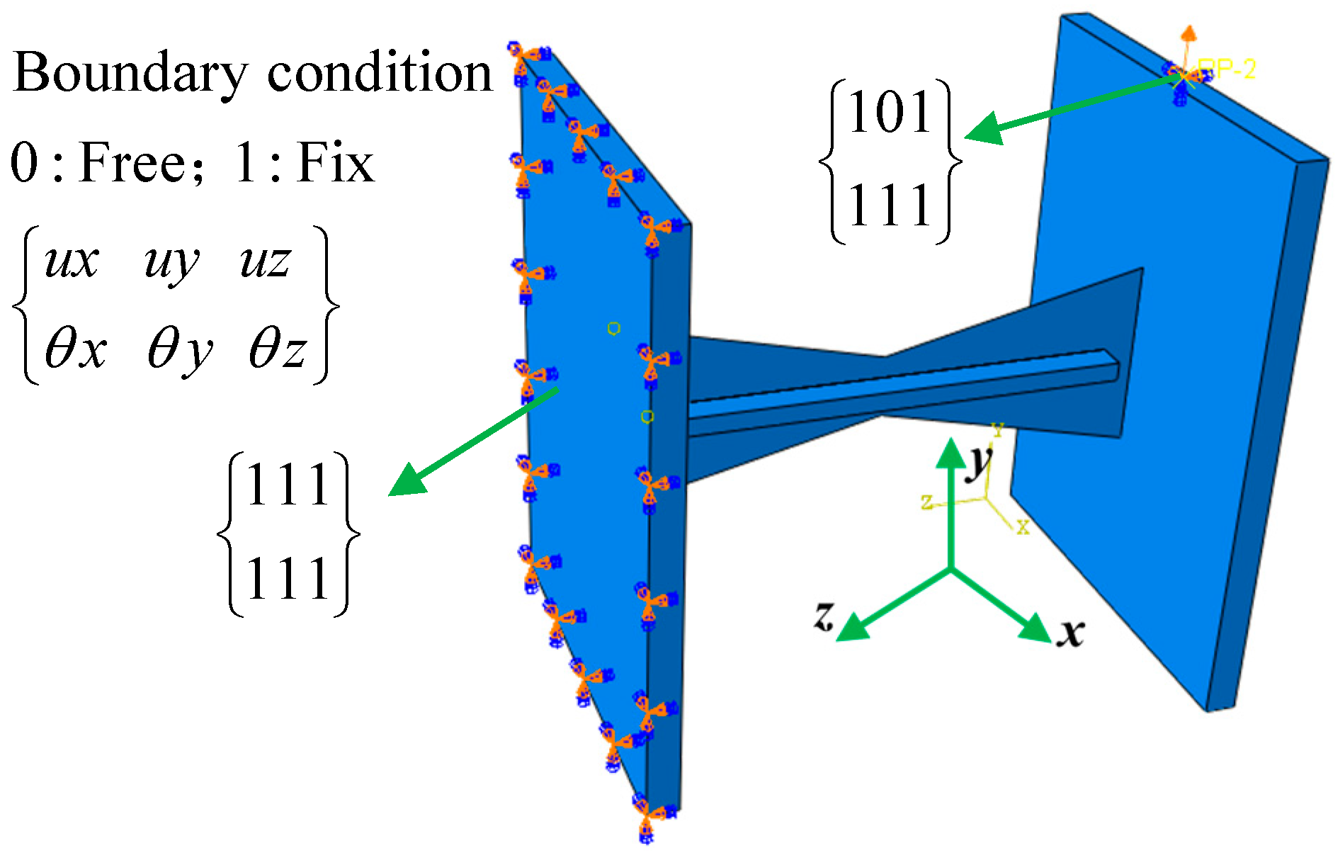
6.1. FEA Model

To further study the hysteretic performance of XMD, a finite element analysis (FEA) model in the commonly used program ABAQUS was established, as shown in Figure 18. An eight-node linear brick 3D element with reduced integration was used to model the connected steel plates and stiffening ribs in this FEA model. When the scale of a component in one direction is much smaller than that in other directions and the stress along the thickness direction is ignored, the mechanical behavior of a component can be modelled by the shell element [41]. Therefore, the X-shaped metal plates were simulated by a four-node quadrilateral shell element. Additionally, the geometric nonlinearity of X-shaped metal plates was taken into account in the FEA model. All freedoms of the left surface of a connected steel plate were fully fixed to simulate the rigid joint. The translational degree of freedom along the y-axis was free to apply the displacement. For specimens with stiffening ribs, the contact surface of stiffening ribs and X-shaped metal plates adopted the surface-to-surface tie constraint to model the welding joints. For specimens with cover plates, the translational degree of freedom along the x-axis was fixed to model the cover plates. However, it can be noted from the test results that the cover plates could not fully constrain the out-of-plane deformation of steel plates. Therefore, the simulated results of specimens were larger than those of the test results for specimens with cover plates. When we applied comprehensive consideration of time cost and computational accuracy, the grid edge lengths of X-shaped metal plates and other components in this FEA model were 5 mm and 6 mm, respectively.

6.2. Material Properties of Steel

To accurately simulate the hysteretic behavior of XMD subjected to cyclic loadings, the metal plasticity model adopting the Von Mises yield criterion, taking into account isotropic and kinematic hardening simultaneously, was used to simulate the steel properties of the XMD [42]. In this metal plasticity model, kinematic hardening behavior is determined via the method of multiple back-stress superposition, which can improve the accuracy of fitting. The isotropic hardening stress and back stress imply the movement of the yield surface and increase in radius of the yield surface, and can be expressed with Equations (19) and (20):
σ 0 = σ 0 + Q ( 1 e b ε p l )
α = k = 1 n C k γ k ( 1 e γ k ε p l )
In the above equations, Ck and γk represent the coefficients of the model. ε p l represents the equivalent plastic strain. Q represents the limit of the isotropic hardening stress. σ|0 represents the initial yield stress. b represents the speed of steel hardening. Additionally, the elastic module (E) and Poisson’s ratio of steel are 200 GPa and 0.3, respectively. According to the method proposed in the ABAQUS user’s manual [41] and by K.H. Nip [43], the above critical parameters can be obtained; the main material properties of the FEM model are listed in Table 4.
Additionally, the previous research results have found that there are inevitable initial defects in real steel structures, resulting in significant differences between theoretical and experimental values of the stable load-bearing capacity of structures. However, the initial defects of structures characterized through the first-order buckling mode have been proven to be an effective method in the simulation of steel structures or components [44]. Therefore, the hysteretic behaviors of XMDs were simulated considering the initial imperfections of steel.

6.3. Comparison of Test and Numerical Results

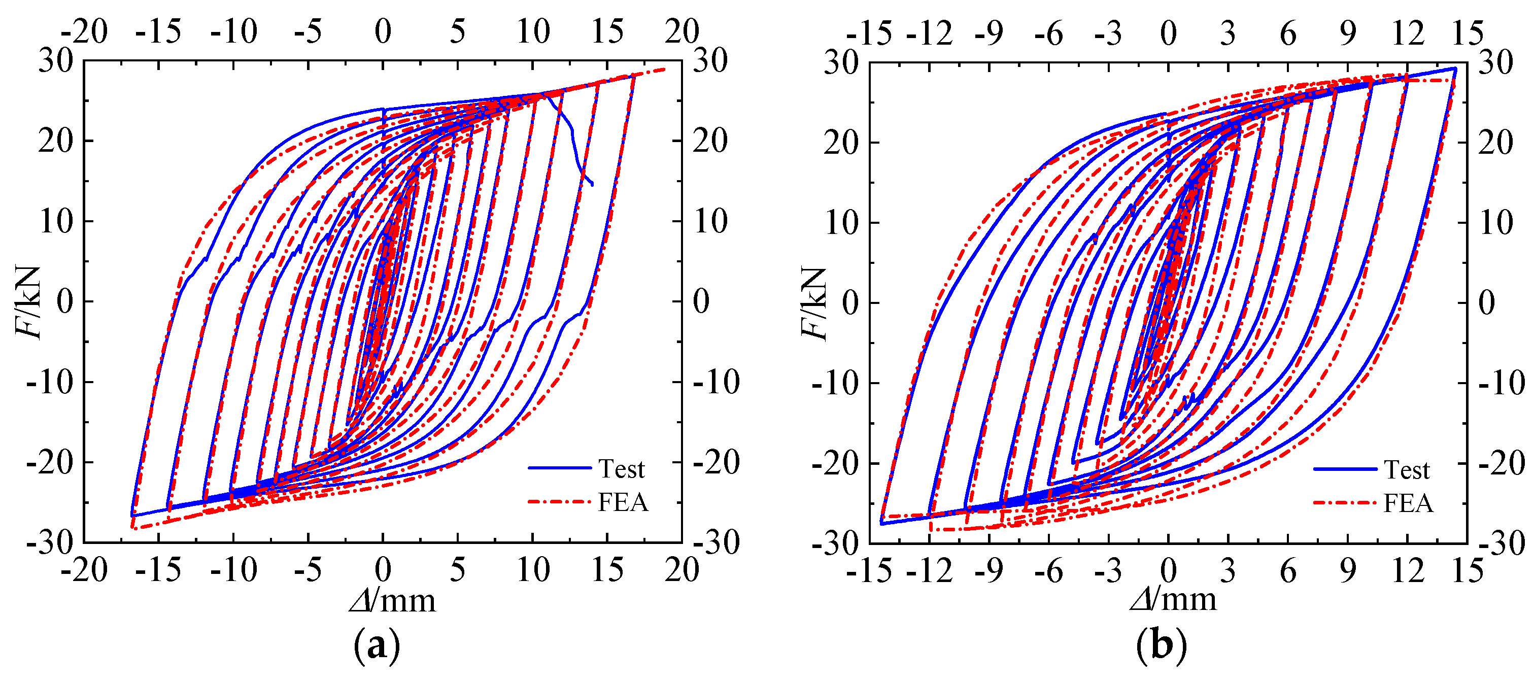
6.3.1. Specimens with Stiffening Ribs

Specimen W20-O0°-LS was taken as an example for the comparison of deformation characteristics of the test and simulation results. It can be noted from Figure 19a,b that specimen W20-O0°-LS showed S-shaped deformation characteristics, consistent with the test results. As shown in Figure 19c, although the buckling behavior of X-shaped metal plates can be restricted by stiffening ribs, slight out-of-plane deformation was observed in specimen W20-O0°-LS. In addition, the simulation results showed that the maximum stress in the region was mainly distributed in the outer edge of the weakened segment of the X-shaped metal plates, which matched well with the theoretical results.
Figure 20 shows the comparison of the hysteretic curves of the test and simulation results. The simulation results matched well with the test results in terms of the hysteretic performance, bearing capacity, and energy dissipation, except for specimen W30-O30°-LS. In comparison to the test hysteretic curves for specimen W30-O30°-LS, the simulation results showed fatter hysteretic loops due to the effect of eccentricity forces resulting from the loading devices.

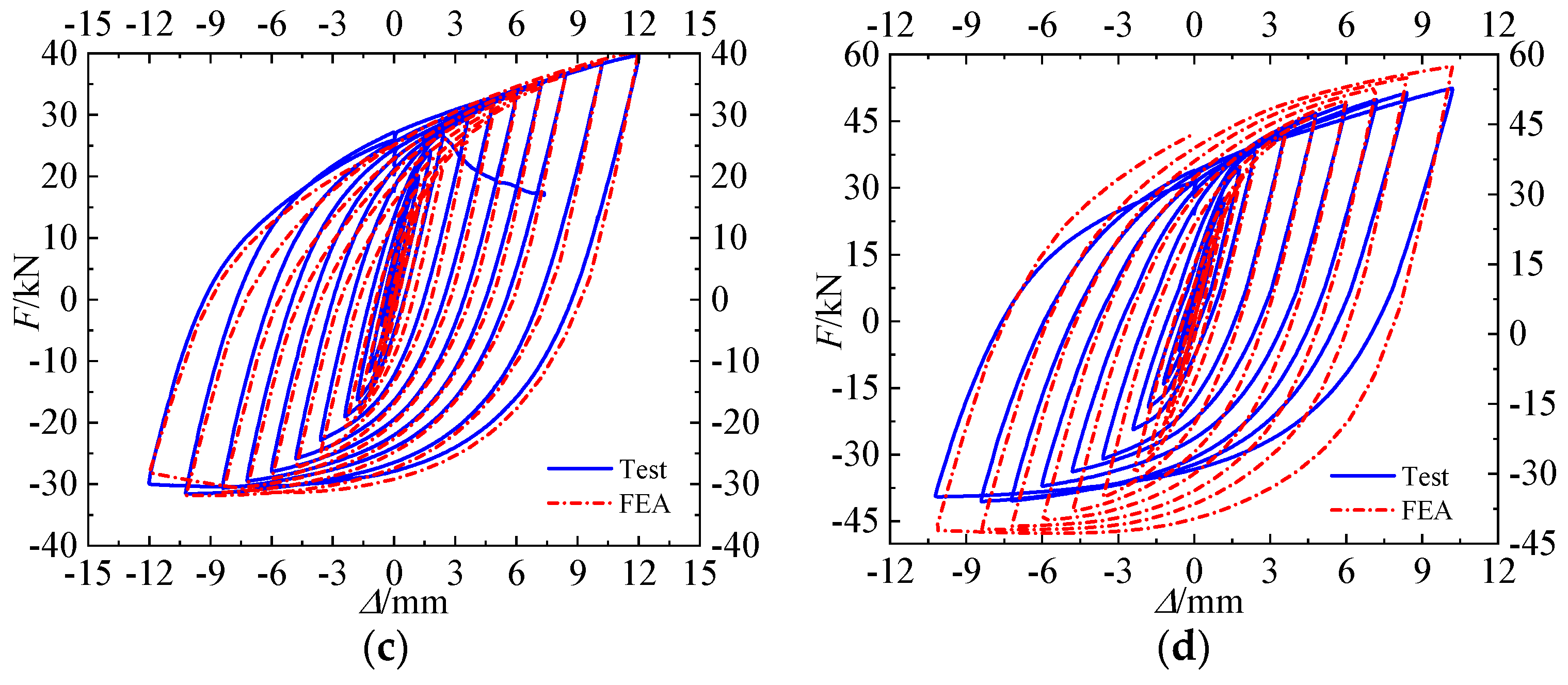
6.3.2. Specimens with Cover Plates

According to the above-proposed FEA model, the cover plates were simulated to restrict the out-of-plane freedom of steel plates. Figure 21 shows the comparison of the hysteretic curves of test and simulation results for specimens with cover plates. As expected, the hysteretic loops of the proposed FEA model were fatter than those of test specimens due to the gap between X-shaped metal plates and cover plates. However, when taking into account the strength and energy dissipation, this proposed FEA model can approximately predict the hysteretic behavior when subjected to cyclic loadings.

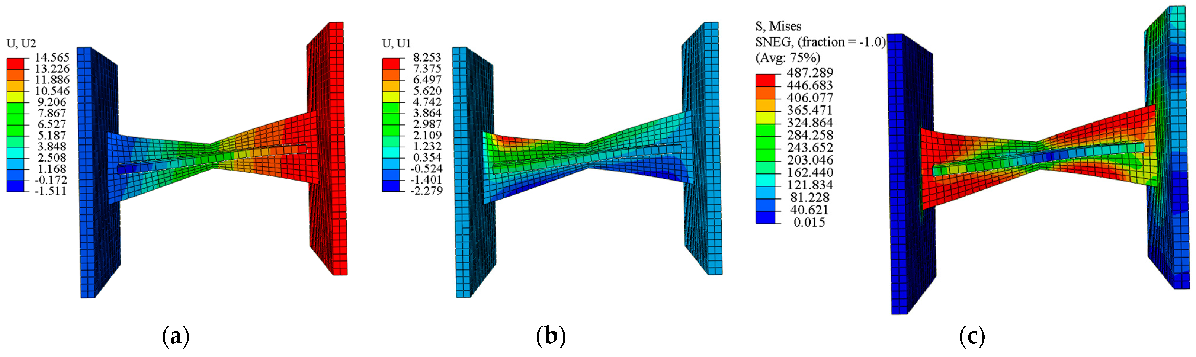
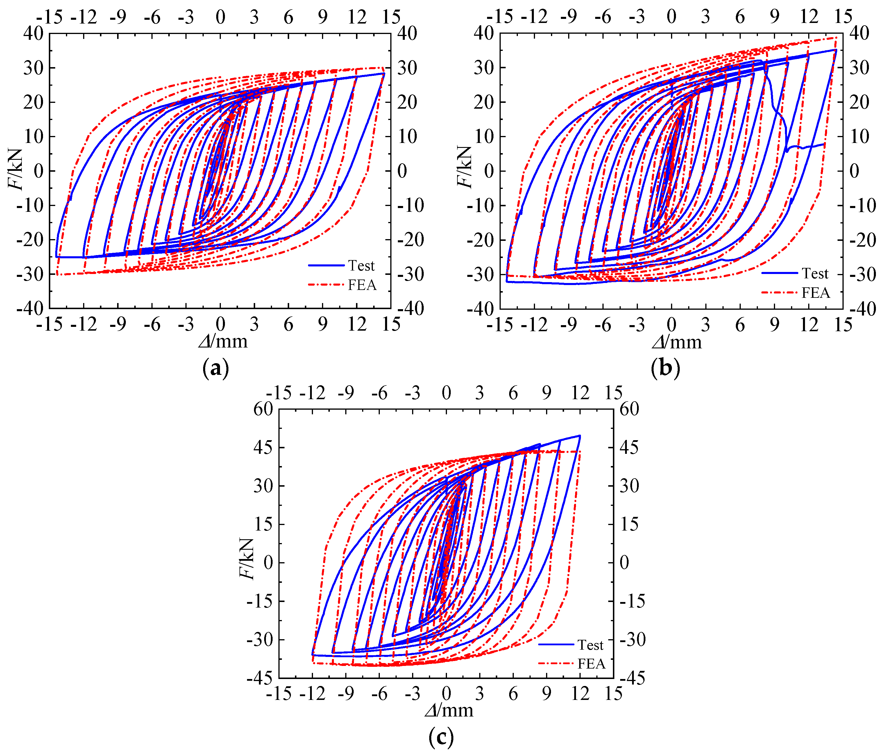
6.3.3. Specimens without Buckling-Restrained Devices

The three-order characteristics of buckling behavior were observed in specimens W30-O15° and W30-O30° without buckling-restrained devices subjected to cyclic loading, as shown in Figure 6 and Figure 7. Just like the simulation method for specimens with buckling-restrained devices, when the first buckling mode was introduced to denote the initial imperfections of the XMD and the modal scaling factor was 0.001, first-order buckling deformation was found in the FEA model, as shown in Figure 22a. When the third-order buckling mode was introduced to denote the initial imperfections of the XMD and the modal scaling factor was 0.001, the deformation characteristics of the simulation results were in accordance with the test results, as shown in Figure 22b. Therefore, the third-order buckling mode was introduced to model the hysteretic behavior of dampers without buckling-restrained devices.
Figure 23 shows the comparison of the hysteretic curves of the test and simulation results for specimens W30-O15° and W30-O30°. As shown in Figure 23, the simulation results of specimens W30-O15° and W30-O30° matched well with the test results. For specimen W30-O30°, the strengths of the FEA model in the initial loading stage were slightly higher than those of the test specimens.
The comparison of experimental and numerical strength at the applied displacement of 12 mm (Δp) based on the proposed FEA model is shown in Table 5, in which Fe and Fn represent the mean strengths of the experimental and numerical results for all specimens. It should be mentioned that the mean strength of specimen W30-O30°-LS at the applied displacement of 10.2 mm was selected for comparison due to welding failure. As shown in Figure 5, the deviation between the mean strengths of experimental and numerical results was about 7–18%, implying better accuracy of the proposed FEA model.

6.4. Potential Improvements

With the development of construction technologies and people’s high demands, resilient precast RC structures may become a key technology in the field of seismic engineering, with the goal of achieving rapid functional recovery after earthquakes. In recent research, X-shaped metal dampers with an oblique angle have been successfully used in the vertical seams of precast monolithic shear walls and self-centering concrete walls to provide additional stiffness, strength, and energy dissipation [34,35]. However, the effect of these metal dampers on reducing the residual displacement of shear walls needs be improved.
As the first seismic fortification line in shear walls with vertical seams, the following potential improvements in X-shaped metal dampers with an oblique angle are proposed, to improve the recoverability of shear walls: 1. X-shaped metal dampers with reasonable design parameters can be machined from shape memory alloy materials. 2. X-shaped metal dampers can be designed with prestressed tendons or disc springs, forming self-centering metal dampers.

7. Conclusions

In this paper, the hysteretic behaviors of X-shaped metal dampers with an oblique angle were investigated experimentally through a series of cyclic loading tests. Additionally, a theoretical method and finite element analysis model were also proposed to predict the elastic stiffness and hysteretic behavior of dampers, respectively. The main conclusions are drawn as follows:
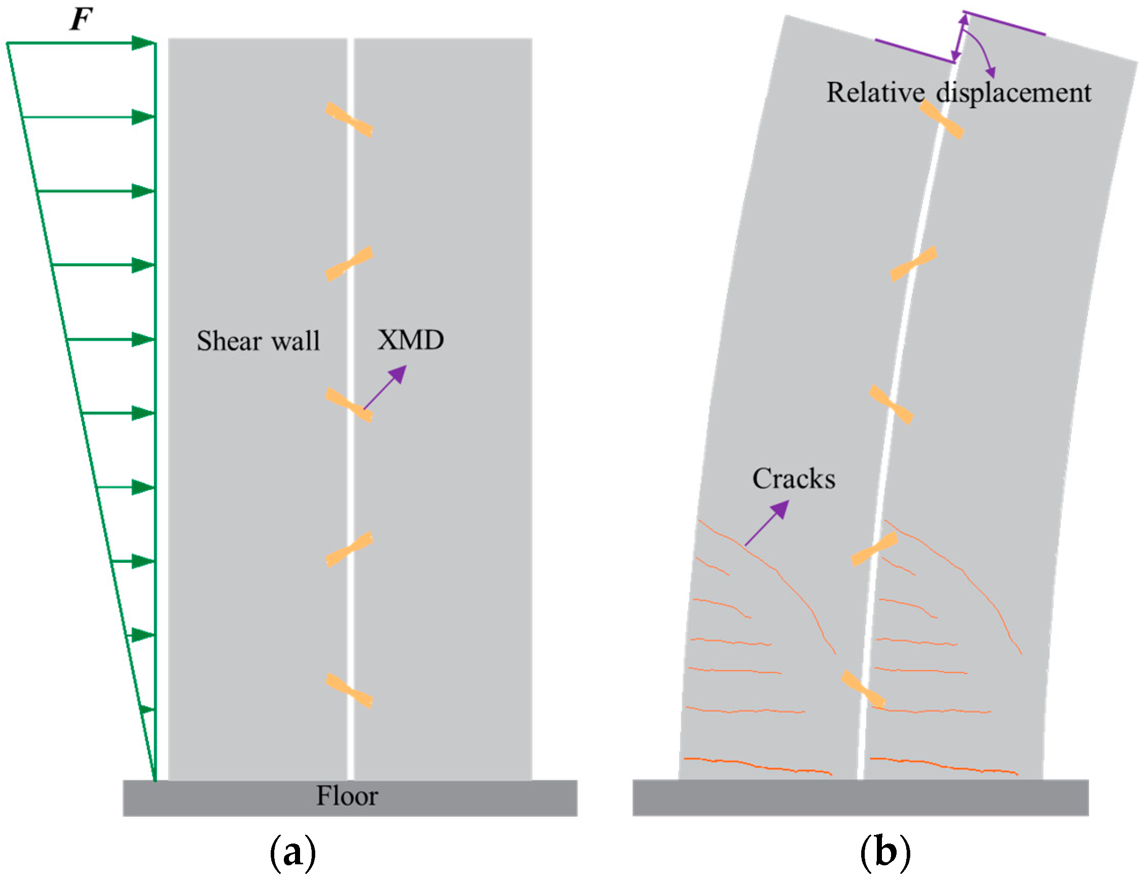
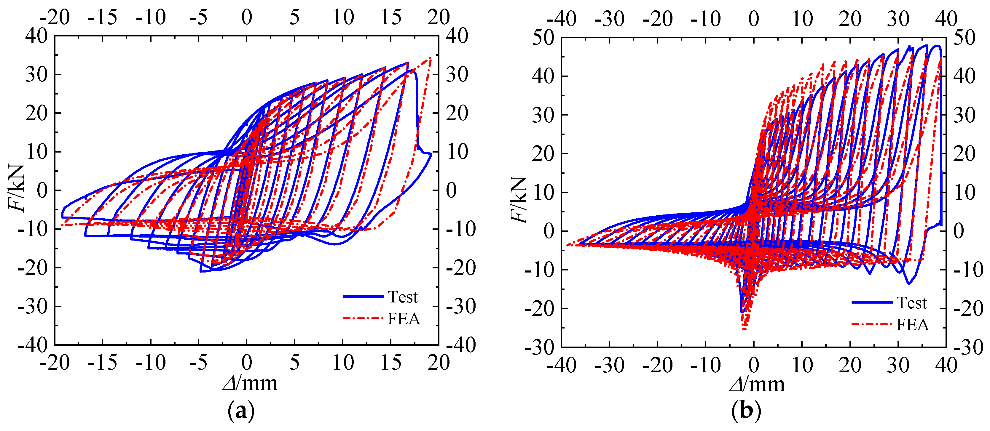
  • In the initial loading stage, parallelogram hysteretic loops were observed in specimens W30-O15° and W30-O30° before reaching the critical buckling load of X-shaped metal plates. After that, obvious buckling behavior was found as specimens were mainly in compression and shear in the negative direction. On the contrary, the tensile behavior of X-shaped metal plates would eliminate the out-of-plane deformation.
  • The stiffening ribs and cover plates can effectively constrain the out-of-plane deformation of X-shaped steel plates. However, due to the tensile and shear behavior of specimens in the positive direction, asymmetric hysteretic loops were also observed in specimens with oblique angles and buckling-restrained devices.
  • The oblique angle could effectively improve the stiffness, strength, and energy dissipation of the XMD. When the oblique angle of the XMD with stiffening ribs increased from 0° to 30° at the applied displacement of 8.4 mm, the mean strengths and cumulative energy dissipation of specimens increased by about 80.77% and 80.57%, respectively. In addition, stiffening ribs with simple design details and higher strength were more suitable for application in engineering structures.
  • A theoretical calculation method was proposed to predict the elastic stiffness of specimens with an oblique angle, and the theoretical elastic stiffness matched well with the tests results. Additionally, the relative deviation for all specimens was approximately 6%, indicating that the proposed method can effectively predict the elastic stiffness of the XMD with an oblique angle.
  • The hysteretic behaviors of specimens with an oblique angle were predicted well using the proposed FEA model. For specimens with cover plates, the hysteretic loops of the proposed FEA model were fatter than those of test specimens due to the gap between X-shaped metal plates and cover plates.

Author Contributions

Conceptualization, X.Z. and L.D.; methodology, S.L.; software, M.Z.; validation, L.D., M.Z., and J.Y.; formal analysis, M.Z and L.D.; investigation, X.Z.; resources, S.L.; data curation, M.Z.; writing—original draft preparation, X.Z. and L.D.; writing—review and editing, J.Y. and X.D.; visualization, L.D. and X.D.; supervision, X.Z. and S.L.; project administration, X.Z.; funding acquisition, X.Z., S.L., and L.D. All authors have read and agreed to the published version of the manuscript.

Funding

This research was funded by the National Natural Science Foundation of China (Grant No. 52308167), Open Research Subject of Architectural Design and Research Institute Ltd., Southeast University (2020-12), China Postdoctoral Science Foundation (Grant No. 2022M723003), Science and Technology Research Project of Henan Province (Grant Nos. 232102321075, 222102320015), and Open Research Subject of Henan Key Laboratory of Grain and Oil Storage Facility & Safety (Grant No. 2022KF07).

Institutional Review Board Statement

Not applicable.

Informed Consent Statement

Not applicable.

Data Availability Statement

The data used to support the finding of this study are included within the article.

Conflicts of Interest

Author Xiaojun Zhu was employed by the company Architects & Engineers Co., Ltd. of Southeast University. The remaining authors declare that the research was conducted in the absence of any commercial or financial relationships that could be construed as a potential conflict of interest. The authors declare that this study received funding from Architectural Design and Research Institute Ltd. The funder was not involved in the study design, collection, analysis, interpretation of data, the writing of this article or the decision to submit it for publication.

References

  1. Zhao, B.; Taucer, F.; Rossetto, T. Field investigation on the performance of building structures during the 12 May 2008 Wenchuan earthquake in China. Eng. Struct. 2009, 31, 1707–1723. [Google Scholar] [CrossRef]
  2. Weng, Y.K.; Pampanin, S. The seismic performance of RC buildings in the 22 February 2011 Christchurch earthquake. Struct. Concr. 2011, 12, 223–233. [Google Scholar]
  3. Xu, G.; Guo, T.; Li, A.Q.; Zhang, H.Y. Self-centering beam-column joints with variable stiffness for steel moment resisting frame. Eng. Struct. 2023, 278, 115526. [Google Scholar] [CrossRef]
  4. Xu, G.; Guo, T.; Li, A.Q. Self-centering rotational joints for seismic resilient steel moment resisting frame. J. Struct. Eng. 2023, 149, 04022245. [Google Scholar] [CrossRef]
  5. Xie, L.L.; Fan, Z.M.; Wang, X.Y.; Zeng, D.M.; Yang, C.T. Investigation on the resilience-based seismic design of isolated RC frame-shear wall structures. Eng. Mech. 2023, 40, 47–57. (In Chinese) [Google Scholar]
  6. Wu, M.; Liu, X.; Liu, H.T.; Du, X.L. Seismic performance of precast short-leg shear wall using a grouting sleeve connection. Eng. Struct. 2020, 208, 110338. [Google Scholar] [CrossRef]
  7. Dang, L.J.; Liang, S.T.; Zhu, X.J.; Zhang, M.; Song, Y.M. Seismic performance of precast concrete wall with vertical energy-dissipating connection. Struct. Des. Tall Spec. Build. 2021, 30, e1820. [Google Scholar] [CrossRef]
  8. Qian, J.R.; Peng, Y.Y.; Zhang, J.M.; Qin, H.; Li, J.S.; Liu, G.Q.; Zhao, F.D.; Li, L.R. Tests on seismic behavior of pre-cast shear walls with vertical reinforcements spliced by grout sleeves. Build. Struct. 2011, 41, 1–6. (In Chinese) [Google Scholar]
  9. Lew, M.; Naeim, F.; Carpenter, L.D.; Youssef, N.F.; Rojas, F.; Saragoni, G.R.; Adaros, M.S. The significance of the 27 February 2010 offshore maule, chile earthquake. Struct. Design Tall Spec. Build. 2010, 19, 826–837. [Google Scholar] [CrossRef]
  10. Kam, W.Y.; Pampanin, S.; Elwood, K. Seismic performance of reinforced concrete buildings in the 22 February Christchurch (Lyttleton) earthquake. New Zealand Soc. Earthq. Eng. 2011, 44, 239–279. [Google Scholar] [CrossRef]
  11. Pampanin, S. Reality-check and renewed challenges in earthquake engineering: Implementing low-damage structural systems- From theory to practice. J. Wuhan Inst. Phys. Educ. 2012, 45, 137–160. [Google Scholar]
  12. Jiang, X.Y.; Song, X.D.; Li, T.; Wu, K.X. Moment magnitudes of two large Turkish earthquakes on February 6, 2023 from long-period coda. Earthq. Sci. 2023, 36, 169–174. [Google Scholar] [CrossRef]
  13. Xu, G.; Li, A.Q. Seismic performance and design approach of unbonded post-tensioned precast sandwich wall structures with friction devices. Eng. Struct. 2020, 204, 110037. [Google Scholar] [CrossRef]
  14. Zhou, Y.; Deng, X.S.; Huang, W.H. Study on seismic control of structure with mixed lead rubber damper. Earthq. Eng. Eng. Vib. 1998, 18, 103–110. (In Chinese) [Google Scholar]
  15. Zhou, Y.; Li, D.B.; Shi, F.; Luo, W.L.; Deng, X.S. Experimental study on mechanical properties of the hybrid lead viscoelastic damper. Eng. Struct. 2021, 246, 113073. [Google Scholar] [CrossRef]
  16. Fang, X.J.; Zhou, Y.; Bi, K.M.; Hao, H.; Wang, T.Y. Experimental study on the cyclic behaviors of an innovative lead-viscoelastic coupling beam damper (LVCBD). J. Build. Eng. 2023, 64, 105596. [Google Scholar] [CrossRef]
  17. Bergman, D.M.; Goel, S.C. Evaluation of Cyclic Testing of Steel Plate Devices for Added Damping and Stiffness; Report No. UMCE87-10; The University of Michigan: Ann Arbor, MI, USA, 1987. [Google Scholar]
  18. Priestley, M.J.N. The PRESSS program-current status and proposed plans for Phase 3. PCI J. 1996, 41, 22–40. [Google Scholar] [CrossRef]
  19. Chen, Y.; Yu, W.H.; Zhang, M.; Li, Y.J. A novel energy dissipation damper for multi-level earthquakes. J. Constr. Steel Res. 2022, 192, 107214. [Google Scholar] [CrossRef]
  20. Youssef, A.A.; Esfahani, M.R.; Zareian, M.S. Experimental evaluation of post-tensioned hybrid coupled shear wall system with TADAS steel dampers at the beam-wall interface. Structures 2023, 53, 1283–1299. [Google Scholar] [CrossRef]
  21. Yang, J.; Liang, S.T.; Zhu, X.J.; Dang, L.J.; Wang, W.K.; Zhou, S.Y. Development and performance research of an Xadas damper with a double-phased yield mechanism. Structures 2023, 24, 1420–1439. [Google Scholar] [CrossRef]
  22. Yang, J.; Liang, S.T.; Zhu, X.J.; Dang, L.J.; Shen, T.H.; Zhou, S.Y. Experimental and theoretical research on a shear-bending-metallic-damper with a double-phased yield mechanism. J. Constr. Steel Res. 2023, 203, 107839. [Google Scholar] [CrossRef]
  23. Kishiki, S.; Zheng, H.W.; Ishida, T.; Tatsumi, N.; Watanabe, A. Inspection of U-shaped steel dampers based on residual plastic deformation. Eng. Struct. 2021, 245, 112915. [Google Scholar] [CrossRef]
  24. Wang, B.; Zhu, S.Y. Superelastic SMA U-shaped Dampers with Self-centering Functions. Smart Mater. Struct. 2018, 27, 055003. [Google Scholar] [CrossRef]
  25. Shen, S.D.; Pan, P.; Miao, Q.S.; Li, W.F.; Gong, R.H. Test and analysis of reinforced concrete (RC) precast shear wall assembled using steel shear key (SSK). Earthq. Eng. Struct. Dyn. 2019, 48, 1595–1612. [Google Scholar] [CrossRef]
  26. Park, J.W.; Yoon, J.H.; Yoon, G.H.; Lim, Y.M. Effect of Dynamic Loading Conditions on Maximizing Energy Dissipation of Metallic Dampers. Appl. Sci. 2022, 12, 3086. [Google Scholar] [CrossRef]
  27. Lin, Y.; Yang, S.; Guan, D.Z.; Guo, Z.X. Modified strip model for indirect buckling restrained shear panel dampers. J. Constr. Steel Res. 2020, 175, 106371. [Google Scholar] [CrossRef]
  28. Lin, Y.; Wang, Y.F.; Wu, W.H.; Yang, S.; Guo, Z.X.; Guan, D.Z.; Li, G.J. Experimental study on PSPC beam–Concrete encased CFST column frame installed with novel steel panel dampers. Eng. Struct. 2023, 288, 116211. [Google Scholar] [CrossRef]
  29. Wang, J.C.; Men, J.J.; Zhang, Q.; Fan, D.X.; Zhang, Z.Y.; Huang, C.H. Seismic performance evaluation of a novel shape-optimized composite metallic yielding damper. Eng. Struct. 2022, 268, 114714. [Google Scholar] [CrossRef]
  30. Guo, L.; Wang, J.F.; Wang, H.L. Seismic design and hybrid simulation test of existing concrete frames upgraded by metallic damper. Eng. Struct. 2023, 291, 116337. [Google Scholar] [CrossRef]
  31. Guan, D.Z.; Peng, Z.H.; Lin, Y.; Liu, J.B.; Zhang, L. Development and seismic performance of precast rocking walls with multiple steel energy dissipaters. Case Stud. Constr. Mater. 2023, 19, e02304. [Google Scholar] [CrossRef]
  32. Bedriñana, L.A.; Tani, M.; Kono, S.; Nishiyama, M. Seismic behavior of unbonded post-tensioned precast concrete walls with internal and external dampers. In Proceedings of the 17th World Conference on Earthquake Engineering, Sendai, Japan, 13–18 September 2020. [Google Scholar]
  33. Wang, B.; Zhu, S.Y.; Zhao, J.X.; Jiang, H.J. Earthquake resilient RC walls using shape memory alloy bars and replaceable energy dissipating devices. Smart Mater. Struct. 2019, 28, 065021. [Google Scholar] [CrossRef]
  34. Dang, L.J.; Liang, S.T.; Zhu, X.J.; Wang, Z.L.; Pang, R.; Yang, J. Development and seismic performance of precast concrete shear wall with vertical connectors subjected to cyclic loading. J. Earthq. Eng. 2023, 27, 2887–2918. [Google Scholar] [CrossRef]
  35. Dang, L.J.; Liang, S.T.; Zhu, X.J.; Pang, R.; Yang, J. Research on seismic behavior of unbonded post-tensioned concrete wall with vertical energy-dissipating connections. J. Build. Eng. 2021, 45, 103478. [Google Scholar] [CrossRef]
  36. Xu, Y.H.; Li, A.Q.; Zhen, H. Experimental study of mild steel dampers with parabolic shape. J. Build. Struct. 2011, 32, 202–209. (In Chinese) [Google Scholar]
  37. AISC Committee on Specifications. Specification for Structural Steel Buildings: ANSI/AISC 360-16; American Institute of Steel Construction: Chicago, IL, USA, 2016. [Google Scholar]
  38. Kenneth, M.L.; Chia, M.U.; Joel, T.L.; Anne, M.G. Fundamentals of Structural Analysis; McGraw-Hill Education: New York, NY, USA, 2018. [Google Scholar]
  39. GB 50010–2010; Code for Design of Concrete Structures. China Architecture & Building Press: Beijing, China, 2010. (In Chinese)
  40. Huo, L.F. Study on Seismic Performance of Slit Shear Wall Based on Metallic Damper. Master Thesis, School of Civil Engineering, Harbin Institute of Technology, Harbin, China, 2015. [Google Scholar]
  41. ABAQUS. ABAQUS Standard User’s Manual, Version 6.13; Dassault Systèmes Corp.: Providence, RI, USA, 2013. [Google Scholar]
  42. Yang, Y.F.; Hou, C.; Liu, M. Experimental study and numerical analysis of CFSST columns subjected to lateral cyclic loading. J. Struct. Eng. 2018, 144, 04018219. [Google Scholar] [CrossRef]
  43. Nip, K.H.; Gardner, L.; Davies, C.M.; Elghazouli, A.Y. Extremely low cycle fatigue tests on structural carbon steel and stainless steel. J. Constr. Steel Res. 2010, 66, 96–110. [Google Scholar] [CrossRef]
  44. Lin, Y.; Guo, Z.X.; Yang, S.; Guan, D. Development of duplex assembled I-shaped steel panel dampers. J. Constr. Steel Res. 2020, 174, 106267. [Google Scholar] [CrossRef]
Figure 1. Application scenarios of XMD with oblique angle in precast shear wall: (a) before loading; (b) after loading.
Applsci 13 12464 g001
Figure 2. Theoretical analysis model: (a) section size; (b) deformation diagram; (c) bending moment.
Applsci 13 12464 g002
Figure 3. The design details of XMD: (a) specimen without an oblique angle; (b) specimen with an oblique angle; (c) specimen without stiffening ribs; (d) specimen with cover plates; (e) photo of specimens.
Applsci 13 12464 g003
Figure 4. Test setup: (a) photo; (b) schematic diagram.
Applsci 13 12464 g004
Figure 5. Loading procedure.
Applsci 13 12464 g005
Figure 6. Test deformation observations of specimen W30-O15°: (a) +4.8 mm; (b) −6.0 mm; (c) +7.2 mm; (d) +14.4 mm; (e) −14.4 mm; (f) +7.2 mm.
Applsci 13 12464 g006
Figure 7. Test deformation observations of specimen W30-O30°: (a) buckling behavior; (b) steel fracture.
Applsci 13 12464 g007
Figure 8. Test deformation observations of specimen W20-O0°-LS: (a) +6.0 mm; (b) +10.2 mm; (c) +16.8 mm; (d) +19.2 mm.
Applsci 13 12464 g008
Figure 9. Test deformation observations of specimens: (a) front view; (b) vertical view.
Applsci 13 12464 g009
Figure 10. Hysteretic curves: (a) W30-O15° and W30-O30°; (b) W30-O0°-LS and W30-O0°-LP; (c) W30-O15°-LS and W30-O15°-LP; (d) W30-O30°-LS and W30-O30°-LP; (e) W20-O0°-LS and W30-O0°-LS.
Applsci 13 12464 g010aApplsci 13 12464 g010b
Figure 11. The skeleton curves of specimens: (a) specimens without buckling-restrained devices; (b) specimens with cover plates; (c) specimens with stiffening ribs; (d) W20-O0°-LS and W30-O0°-LS.
Applsci 13 12464 g011
Figure 12. Idealized hysteretic loop.
Applsci 13 12464 g012
Figure 13. Cumulative energy dissipation of specimens: (a) specimens with cover plates; (b) specimens with stiffening ribs.
Applsci 13 12464 g013
Figure 14. Equivalent viscous damping coefficients of specimens: (a) specimens with cover plates; (b) specimens with stiffening ribs.
Applsci 13 12464 g014
Figure 15. Calculating diagram of XMD.
Applsci 13 12464 g015
Figure 16. Internal force distribution of XMD: (a) bending moment; (b) shear force; (c) axial force.
Applsci 13 12464 g016
Figure 17. Schematic section of XMD.
Applsci 13 12464 g017
Figure 18. FEA model of specimens.
Applsci 13 12464 g018
Figure 19. Simulation results of specimen W20-O0°-LS: (a) in-plane deformation; (b) out-of-plane deformation; (c) stress distribution.
Applsci 13 12464 g019
Figure 20. Comparison of numerical and experimental results: (a) specimen W20-O0°-LS; (b) specimen W30-O0°-LS; (c) specimen W30-O15°-LS; (d) specimen W30-O30°-LS.
Applsci 13 12464 g020aApplsci 13 12464 g020b
Figure 21. Comparison of simulation and test results: (a) specimen W30-O0°-LP; (b) specimen W30-O15°-LP; (c) specimen W30-O30°-LP.
Applsci 13 12464 g021
Figure 22. Deformation behavior of specimens W30-O15° and W30-O30°: (a) FEA model of W30-O15°; (b) FEA model of W30-O30°.
Applsci 13 12464 g022
Figure 23. Comparison of simulation and test results: (a) specimen W30-O15°; (b) specimen W30-O30°.
Applsci 13 12464 g023
Table 1. The design details of an oblique X-shaped metal damper.
SpecimenWeakened SegmentHorizontal SegmentThickness/mmAngle
Length/mmWidth/mmLength/mmWidth/mm
W30-O15°150302060615°
W30-O30°150302060630°
W20-O0°-LS15020206060
W30-O0°-LS1503020606
W30-O15°-LS150302060615°
W30-O30°-LS150302060630°
W30-O0°-LP15030206060
W30-O15°-LP150302060615°
W30-O30°-LP150302060630°
Table 2. The characteristic test results of the specimens.
SpecimenDirectionΔ/mmF/kNFm/kNEd/(kN·mm)he
W30-O15°Positive8.428.3321.8387.440.33
Negative−8.4−15.27
W30-O30°Positive8.431.3518.86250.520.23
Negative−8.4−6.36
W20-O0°-LSPositive8.423.9523.25405.120.33
Negative−8.4−22.56
W30-O0°-LSPositive8.426.1725.43448.940.33
Negative−8.4−24.69
W30-O15°-LSPositive8.436.5833.62601.350.34
Negative−8.4−30.65
W30-O30°-LSPositive8.451.3745.97810.680.33
Negative−8.4−40.57
W30-O0°-LPPositive8.425.7124.56503.780.39
Negative−8.4−23.41
W30-O15°-LPPositive8.429.8828.25575.710.39
Negative−8.4−26.62
W30-O30°-LPPositive8.446.440.19708.30.33
Negative−8.4−33.99
Table 3. The comparison of experimental and theoretical results.
SpecimenKe/(kN/mm)Kt/(kN/mm)Ke/Kt
W30-O15°13.2315.090.88
W30-O30°17.2915.13 1.14
W30-O0°-LP13.0515.080.87
W30-O15°-LP15.1615.091.00
W30-O30°-LP20.1315.13 1.33
W30-O0°-LS12.8615.080.85
W30-O15°-LS16.5716.071.03
W30-O30°-LS21.9319.60 1.12
Table 4. Material properties of FEM model.
σ|0/MPaE/GPaνC1γ1Qb
316.112000.362,1051611535
Table 5. The comparison of experimental and numerical results.
Specimen Δp/mmFe/kNFn/kNFn/Fe
W30-O15°12.0021.1819.660.93
W30-O30°12.0020.2723.851.18
W20-O0°-LS12.0025.2326.001.03
W30-O0°-LS12.0027.2628.401.04
W30-O15°-LS12.0034.9034.280.98
W30-O30°-LS10.2045.8952.181.14
W30-O0°-LP12.0026.2629.571.13
W30-O15°-LP12.0031.9833.901.06
W30-O30°-LP12.0042.8241.240.96
Disclaimer/Publisher’s Note: The statements, opinions and data contained in all publications are solely those of the individual author(s) and contributor(s) and not of MDPI and/or the editor(s). MDPI and/or the editor(s) disclaim responsibility for any injury to people or property resulting from any ideas, methods, instructions or products referred to in the content.

