Review

Breaking Boundaries in Wind Engineering: LSU WISE Open-Jet Facility Revolutionizes Solar Panel and Building Design

Windstorm Impact, Science, and Engineering (WISE) Laboratory, Louisiana State University (LSU), Baton Rouge, LA 70803, USA
Appl. Sci. 2023, 13(23), 12546; https://doi.org/10.3390/app132312546
Submission received: 4 October 2023 / Revised: 10 November 2023 / Accepted: 15 November 2023 / Published: 21 November 2023

Abstract

:

Featured Application

The Louisiana State University (LSU) Windstorm Impact, Science, and Engineering (WISE) Open-Jet Testing facility is instrumental in enhancing structural resilience under windstorms. The facility represents a Mid-Scale Research Infrastructure to address grand challenges and the need for experimental capabilities in the mid-scale range. Its unique capabilities enable the comprehensive testing and evaluation of critical infrastructure components, encompassing low- and high-rise buildings, photovoltaic (PV) solar panels, wind turbines, bridges, vegetation (nature-based solutions), power transmission lines, and more. Through controlled wind conditions, researchers can gain invaluable insights into the behaviour and performance of these critical infrastructures. The facility is pivotal in advancing the design and engineering of robust, climate-resilient systems capable of withstanding the challenges posed by dynamic environmental conditions. The potential impact of this wind testing facility extends far beyond the boundaries of conventional engineering, offering a pathway towards a more sustainable and resilient built environment on a global scale.

Abstract

Experimental wind engineering is crucial for global structural design. This paper addresses limitations in aerodynamic testing, particularly in wall-bounded and small-scale scenarios. Open-jet testing, introduced as an advanced tool, overcomes turbulence modelling constraints, providing a more accurate representation of real-world conditions. The LSU WISE open-jet facility produces complete turbulence at a large scale, eliminating the need for corrections accompanied by partial turbulence simulation. This discovery holds significant implications in wind engineering and unsteady aerodynamics. Integrating photovoltaic panels with gable-roofed buildings may not require additional structural reinforcement, with a reduction in wind uplift forces by 45–63%. Building-integrated photovoltaics (BIPV) offer design flexibility and aesthetic appeal despite potential higher upfront costs. Strategic interventions, such as design optimization and cost-effective installation methods, can enhance the economic viability of BIPV systems. Contrary to long-held beliefs, the findings challenge the notion that wind loads on structures with sharp corners are insensitive to Reynolds number. Open-jet testing produces higher peak pressures, providing real-world justification for actual damage in high-rise buildings. These results validate the author’s hypothesis regarding the underestimation of peak loads (in small-scale testing) leading to cladding failure in high-rise buildings. They emphasize the superiority of large-scale open-jet testing, underscoring its critical role in designing resilient structures. The LSU WISE open-jet facility’s unique capabilities hold immense promise for revolutionizing wind engineering, addressing grand challenges, and creating more resilient and sustainable infrastructure. Its applications span critical infrastructure, promising significant economic, societal, and educational impacts in STEM fields.

1. Introduction

1.1. Significance and Challenges in Wind Engineering

The field of wind engineering has witnessed a growing significance, particularly concerning the aerodynamic performance of buildings and renewable energy infrastructure. This importance stems from the increasing intensity and frequency of extreme wind events, such as hurricanes/typhoons, which substantially damage the built environment [1,2]. The challenges posed by extreme wind events face both low- and high-rise buildings [3]. With most constructed buildings worldwide falling into the low-rise category, the structural integrity of these buildings is of paramount importance [4,5]. While seismic considerations are critical in high-risk zones, wind loads pose a significant challenge, especially in open terrains, coastal areas, and elevated regions [6].
The aerodynamic behaviour of buildings, whether low- or high-rise, is complex and influenced by various factors, including wind velocity, turbulence intensity, terrain, and building geometry [4,7,8,9]. The unpredictable nature of wind loads further exacerbates this complexity during storms, which fluctuate in magnitude, direction, and distribution over time [6]. Buildings, in particular, exhibit bluff body characteristics, experiencing downstream abnormal pressure gradients leading to boundary layer separation [10].
In recent years, the frequency and intensity of hurricanes and other extreme weather events have increased, resulting in widespread damage to buildings and other structures [11,12,13,14,15,16,17,18,19,20]. The economic losses from such events are substantial, underscoring the urgent need for more resilient building designs. Low-rise buildings, commonly found in coastal and open terrain areas, are especially vulnerable to windstorms. Their typically non-engineered construction makes them more susceptible to wind-induced damage. Understanding and accurately simulating wind loads on these structures and their components, such as roof-mounted solar panels, is crucial for improving their design, resilience, and sustainability [10,21,22].
In the case of high-rise buildings, their proliferation is driven by the need for sustainable urban development, allowing for increased population density on limited land [23]. However, their heightened elevation makes them particularly sensitive to wind loads [24]. The aerodynamic intricacies of high-rise structures, including flow separation, wake development, and vortex formation, lead to fluctuating pressures on their façades, potentially inducing structural responses and damage to cladding [25]. The increased incidence of extreme wind events further emphasizes the importance of understanding and mitigating wind-induced damage to high-rise buildings.
Given these challenges, aerodynamic testing is pivotal in evaluating wind effects on buildings. However, traditional wall-bounded laboratory testing has limitations, particularly in replicating complete turbulence at high Reynolds numbers, which are crucial for accurately mimicking real-world conditions [26,27]. Recent studies advocate for large-scale testing facilities, such as the open-jet facility at Louisiana State University (LSU), which generates complete turbulence at higher Reynolds numbers, with minimal blockage effects [27,28]. These advances in testing techniques enable a more accurate estimation of wind pressures on buildings, ultimately contributing to developing more resilient and wind-resistant structural designs.
The combined insights from this paper aim to lay the foundation for a comprehensive understanding of the challenges posed by extreme wind events on both low- and high-rise buildings, as well as buildings with solar panels, and draw attention to a pioneering approach, which promises a paradigm shift in structural resilience and design, with a vision for revolutionizing wind engineering for many applications. This paradigm shift will advance the wind engineering and structural design field by addressing the complexities of aerodynamic behaviour, Reynolds number effects, and the performance of the natural and manmade built environments.

1.2. Urgency for Advancing Wind Engineering Practices

Recent studies have shed light on the escalating costs associated with wind-related damage, emphasizing the urgency of advancing wind engineering practices. The United States, in particular, has experienced a surge in financial losses due to extreme weather events, with hurricanes accounting for a significant portion of the economic impact [29]. The unprecedented damage caused by hurricanes Harvey, Irma, and Maria in 2017 and subsequent storms like Hurricane Laura in 2020 underscores the need for resilient structural systems in low- and high-rise buildings, as well as solar panels [30,31,32,33,34]. These events have prompted a re-evaluation of design provisions and practices to ensure the safety and integrity of the built environment.
Wind tunnel testing has traditionally been the cornerstone of wind engineering studies, providing insights into the behaviour of structures under wind loads. However, discrepancies between wall-bounded laboratory results and real-world field measurements have been noted, raising questions about the accuracy of scaled modelling and the effects of low Reynolds number [26,27,35,36,37,38]. The limitations imposed by the Reynolds number law of similitude have prompted a shift towards large-scale testing, which can replicate full-scale physics [19,27,39]. This has spurred the development of advanced testing facilities, such as the LSU WISE open-jet facility, which offers advantages in generating complete turbulence and accurately simulating real-world conditions [27,40,41].
Despite advancements in wind engineering, there remains a critical need for research addressing the unique challenges of low- and high-rise buildings. These structures’ complex geometries and substantial heights introduce aerodynamic intricacy that necessitates specialized investigation. The influence of aspect ratios on aerodynamic loads, particularly concerning cladding elements, glass, and windows, requires in-depth exploration [42]. Additionally, understanding the implications of Reynolds number effects on wind pressures is crucial for refining design provisions and ensuring the resilience of buildings.

1.3. Knowledge Gap and Advancements in Wind Engineering

The existing body of research in wind engineering and structural design reveals a significant gap in addressing the unique aerodynamic challenges posed by buildings and their components. Recent studies highlight escalating financial losses attributed to wind-related damage, particularly in extreme weather events such as hurricanes [29,30,31,32,33]. This paper aims to bridge this knowledge gap by highlighting large-scale open-jet testing at high Reynolds numbers, explicitly focusing on roofs, solar panels, and cladding elements.
The paper holds immense practical implications for the architectural and engineering communities. Improved insights into the aerodynamic behaviour of buildings, particularly in the context of complete turbulence and higher Reynolds numbers, will enable designers to make more informed decisions, leading to the development of structures exhibiting enhanced resilience against extreme wind events. Additionally, incorporating advanced testing techniques, such as the LSU WISE open-jet approach, represents a significant advancement in the field, allowing experiments under complete turbulence at higher Reynolds numbers with minimized blockage effects.
In essence, these efforts add to the body of knowledge in wind engineering and catalyses future advancements, setting a precedent for more rigorous and comprehensive approaches to structural design. Moving forward, this paper seeks to establish a framework to inform more accurate design practices for buildings of different types and sizes, ultimately enhancing the resilience of structures against extreme wind events.

1.4. Paper Layout

Figure 1 presents a flowchart depicting the layout of the paper. In Section 2, small-scale laboratory testing and its limitations in replicating full-scale physics are delved into, to address the challenges associated with wall-bounded studies, highlighting the need for alternative approaches. Section 3 then introduces the concept of open-jet testing, emphasizing its potential advantages in replicating real-world conditions. Building upon this foundation, Section 4 offers a detailed exploration of large-scale open-jet testing applied to low-rise buildings, providing insight into methodologies and findings. Shifting focus, Section 5 examines the resilience of roof-mounted solar panels under high wind loads, covering wind effects, structural integrity, and aerodynamic testing outcomes. Section 6 extends the discussion to large-scale open-jet testing for cladding design in high-rise buildings, elucidating the objectives and scale effects of the study. In Section 7, a discussion of results is engaged, categorizing findings based on building type and integration with solar panels. In Section 8, potential avenues for future research are explored, including harmonizing solar panels with architectural aesthetics and advancements in building-integrated photovoltaics (BIPV). Section 9 outlines a vision for open-jet testing, encompassing various areas of future research and application, from the wind performance of different infrastructure and aerodynamic systems to educational initiatives. Finally, in Section 10, the key findings and implications of the paper are synthesized, emphasizing their broader impact on resilience and sustainability.

2. Challenges in Wall-Bounded Aerodynamic Testing

In wind engineering research, accurately emulating wind attributes in a controlled environment is crucial to understanding a structure’s reaction to designated wind scenarios. This necessitates the initial replication of wind flow characteristics as per a standardized methodology. Following this, aerodynamic examinations are executed to produce wind-induced pressures and forces acting upon the facades and the structure while upholding the principles of similitude [43]. To satisfy these prerequisites, diverse techniques are employed for simulating atmospheric boundary layer (ABL) flows, including laboratory and computational approaches [44].
Wind tunnel modelling, assumed to be indispensable for assessing wind-induced pressures and loads on structures, has been considered fundamental for numerous decades. However, challenges arise in replicating turbulence and associated physics accurately, especially in wall-bounded laboratory settings [45]. Achieving spectral fidelity with authentic wind patterns at high Reynolds numbers has been a challenge, impacting the accuracy of laboratory experiments [46]. Scaling factors introduce complexities [26,47]. However, larger test models in wall-bounded test sections can alleviate some issues but introduce disparities [47].
The aerodynamic characteristics of structures immersed in turbulent flows are intricately linked to wind patterns’ spatial and temporal dynamics [48]. Understanding peak loads and the spatial pressure interrelation necessitates realistic flow production aligned with full-scale conditions. Challenges arise in replicating the complete turbulence spectra at considerable scales [49,50,51].
Disparities exceeding 50% in aerodynamic metrics have been observed across research laboratories, emphasizing the importance of novel and advanced wind testing [52]. The feasibility of accurately estimating wind-induced loads for design considerations solely reliant on small-scale wall-bounded wind testing outcomes is questioned [53]. The realistic replication of low-frequency turbulence poses a challenge in conventional wall-bounded laboratory experimentation [54].
Figure 2 provides an overview of the observed lack of large-scale turbulence, specifically low-frequency turbulence, in wall-bounded laboratory testing scenarios. In subfigure (a), at a scale of 1:300, the high turbulence flow aligns well with the intended target, demonstrating a successful match. However, in subfigure (b), at a scale of 1:10, the high-turbulence flow deviates significantly from the target, indicating a lack of congruence. Subfigure (c) emphasizes the issue with the normalization of frequency (x-axis) using the flow integral length scale. It is important to note that while this approach may seem intuitive, it can potentially lead to misleading conclusions as it conceals the underlying deficiency in turbulence production, a recurrent issue in prior wall-bounded laboratories.
Small-scale testing presents challenges such as spectra mismatch, Reynolds number effects, blockage issues. Besides, concerns about solar panel damage, and cladding failures on low- and high-rise buildings raise questions about the previous aerodynamic testing methods and design approaches that have been followed for decades [34,55,56,57,58]. Addressing these challenges necessitates advanced studies, and motivates the consideration of a novel testing approach, which is crucial for the safety and dependability of structures when subjected to wind loads.

3. Open-Jet Testing

Full-scale wind testing on buildings and other structures is ideal; however, achieving a 1:1 scale flow that accurately replicates genuine windstorm attributes poses significant challenges [27]. A facility that generates a 1:1 scale flow would necessitate immense blowers positioned at a distance surpassing what a practicable facility could accommodate. Synthetic wind exhibits substantial high-frequency turbulence and lack of low-frequency turbulence at higher Reynolds numbers, imposing restrictions on the size of vortices, thus rendering the scaling of buildings an inevitable requirement for realistically reproducing authentic physics. While there are testing capabilities encompassing large-scale residential structures, the flow characteristics introduce critical questions regarding their resemblance to full-scale ones [59]. Therefore, the scaling of test objects remains imperative for upholding accurate physics. Concurrently, large-scale testing, albeit not full-scale, promises an enhancement in the Reynolds number and its associated aerodynamics. The evolution of large-scale wind testing has undergone various stages before attaining its current state [44,60]. However, turbulence is fundamental for the understanding of aerodynamics, as well as for optimizing the performance of various systems [61].
In the pursuit of advancing capabilities in simulating the atmospheric boundary layer (ABL) and understanding the flow mechanism and aerodynamics responsible for the formation of peak loads that cause failure to buildings, the author led a research team to establish the Windstorm Impact, Science and Engineering (WISE) Laboratory, situated at Louisiana State University (LSU), and undertook the construction of a compact open-jet facility in 2013 [45,60,62] (Figure 3). The principle behind open-jet testing lies in its absence of physical enclosures, offering two primary advantages: (i) the generation of larger eddies, resulting in higher peak pressures akin to those observed at full scale, and (ii) a reduction in blockage effects [63]. The primary objective of this apparatus was to physically replicate hurricane-induced wind patterns resembling those encountered in open and suburban terrains.
Reduced-scale replicas of low-rise structures were subjected to experimental scrutiny to ascertain the impact of approaching flow turbulence characteristics, scale considerations, and the proximity effect of the open-jet exit on the flow dynamics around low-rise buildings [45]. Additionally, the study delved into the alterations in separation bubble length occurring on the roof surface. Specifically, the investigation sought to elucidate the correlation between these variables and the magnitudes of peak pressures exerted on the roof, as detailed in the author’s previous studies [45,60]. Employing a modifiable turbulence generation mechanism, diverse wind profiles were physically emulated.
A multidisciplinary research team at LSU, comprising experts from Civil and Environmental Engineering, Mechanical Engineering, Coast and Environment, Louisiana Sea Grant, Geography and Anthropology, Construction Management, and Sociology, collaborated on a project entitled ‘Hurricane Flow Generation at High Reynolds Number for Testing Energy and Coastal Infrastructure’, which received funding from the Louisiana Board of Regents [64]. The objective was to establish an extensive hurricane testing facility. This facility facilitates the production of high Reynolds number wind flows over a test section measuring 4 m × 4 m (see Figure 4). These capabilities empower the execution of wind engineering experiments at a notably large scale. Furthermore, the generously sized open-jet facility possesses the potential for conducting destructive testing on models constructed from authentic construction materials. Blockage is minimized as per the principles of open-jet testing [63]. This state-of-the-art facility is adept at generating authentic hurricane wind turbulence by realistically replicating the complete spectra of velocity at a large scale and high Reynolds numbers.
The facility demonstrates proficiency in generating mean wind speed and turbulence profiles that emulate open-terrain environments [63]. A suite of advanced instruments, including cobra probes, load cells, laser displacement sensors, and a 256-channel pressure scanning system, are available at the WISE laboratory. These instrumental resources allow advanced testing to capture and scrutinize the data garnered during experimental trials.
The large LSU WISE open-jet facility is a critical platform for researchers to validate their conceptual frameworks, advancing knowledge and fostering breakthroughs in science, hurricane engineering, materials, and structures. The goal is fortifying infrastructure, making it more resilient and sustainable.
The LSU WISE open-jet facility is a cutting-edge establishment offering distinctive capabilities for subjecting buildings to realistic wind loads [42,57,63]. Noteworthy features and functionalities encompass high Reynolds number testing, authentic turbulence generation, comprehensive wind flow analysis, and large-scale experimentation, crucial for accurately simulating flow patterns around buildings in the ABL. It proficiently generates turbulence patterns that closely mimic real-world scenarios, enabling the precise characterization of wind loads on structures. Additionally, the facility accurately reproduces the entire wind flow characteristics encircling buildings, including mean and peak pressures, closely mirroring observations in actual environmental settings. This facility stands as an invaluable instrument for both researchers and engineers dedicated to structural wind engineering. Presented subsequently are three distinct open-jet studies.

4. Study 1: Aerodynamics of Low-Rise Buildings: Large-Scale Open-Jet Testing

4.1. Background

The capricious and intricate nature of turbulent winds confers upon the prediction of aerodynamic loads a formidable challenge. The fidelity of such load prognostication hinges upon the accuracy in replicating turbulence intensity, integral length scale, and Reynolds number effects. The optimal scenario entails the realistic reproduction of features intrinsic to full-scale real-world conditions within the laboratory, and for accurate load prediction, it is imperative to ensure the presence of both small- and large-scale turbulence in the incident flow. This necessitates the laboratory’s capability to replicate low-frequency (large) and high-frequency (small) velocity fluctuations with commensurate energy. In wall-bounded wind testing settings, low-frequency turbulence often lacks sufficient energy, leading to an inability to generate peak loads that cause failure. This limitation contributes to disparities in estimating peak pressures between wall-bounded experiments and their corresponding full-scale counterparts [27]. Adopting higher Reynolds numbers in aerodynamic testing, employing the open-jet concept, is anticipated to enhance the capacity for generating turbulence across the entire frequency spectrum. Consequently, open-jet testing is expected to yield higher peak aerodynamic loads than those derived from conventional small-scale testing [27].

4.2. Methods

The LSU open-jet facility exhibits proficiency in conducting extensive testing characterized by elevated Reynolds numbers, encompassing destructive trials. Two cubic building prototypes, scaled at 1:13 and 1:26 proportions, were fabricated utilizing wooden elements and panels. The scaled building models were tested at the open-jet facility, and the results were compared with those obtained from a 1:100 scale wind tunnel model [63]. The authentic stature of the cubic model at full scale measures 16 m. Velocity measurements were acquired at diverse along-wind positions within the open-jet facility and at varying elevations, aiming to discern an optimal scale and location for experimentation. Furthermore, mean and peak pressures are methodically computed through statistical analysis after recording pressure-time records via pneumatic conduits and Scanivalve pressure scanning system. The sensitivity of surface pressures to Reynolds number effects was also scrutinized.

4.3. Findings

Figure 4 introduces the LSU open-jet test setup, featuring an adjustable flow management apparatus positioned at the forefront of the blowers. This device facilitates the creation of an optimal mean velocity and turbulence profile, representative of different terrain conditions within the test section.
Figure 5 displays the along-wind velocity characteristics and turbulence profile. The LSU WISE facility is unique in producing complete turbulence, compared to another facility requiring post-processing corrections to compensate for the lack of turbulence [51]. It is worth mentioning that, in the literature, partial turbulence simulation was adapted due to inability to produce complete turbulence at a large scale (a lack of low-frequency turbulence is depicted in Figure 6 of Azzi et al. [59]). The turbulence generated by the LSU WISE open-jet system is unique as it adheres to the theoretical spectrum, encompassing both small- and large-scale components at higher Reynolds numbers [42]. This discovery holds significant implications in the realm of experimental wind engineering and unsteady aerodynamics.
Using the open-jet concept in testing contributes to generating large-scale turbulence within the facility, further advancing the understanding of aerodynamic behaviours in practical applications.
Table 1 delineates Reynolds numbers pertinent to varying scales. The pressure coefficients are qualitatively assessed in the form of (a) contour plots to compare with TPU results. The two models were tested at two different velocities for each location that generate multiple Reynolds number cases (Table 1). More details about this study are available in [63].
Figure 6 and Figure 7 conspicuously illustrate the escalating trend in mean and 95% quantile peak pressure coefficients concomitant with augmented Reynolds numbers. Furthermore, the findings evince the presence of a more expansive separation bubble in the open-jet scenario as opposed to small-scale testing, inducing a progressive decline in pressure downstream on the roof. These promising outcomes undeniably advance aerodynamic testing of low-rise edifices towards a scenario mirroring full-scale conditions. Examining such sizable structures at elevated Reynolds numbers in the open-jet environment has substantiated heightened local peak pressures. These outcomes exert substantial influence on the refinement of extant building standards.

5. Study 2: Resilience of Roof-Mounted Solar Panels to High Wind Loads

5.1. Wind Effects on Roof-Mounted Photovoltaic Panels

In contemporary society, a notable facet of infrastructure subject to heightened wind forces encompasses roof-mounted solar panels. This is particularly pertinent given that solar energy constituted a 56% of newly added electricity-generating capacity within the United States during the initial half of 2021. The installation rates of residential solar panels reached historically elevated levels in 2020 and 2021. Consequently, a pressing imperative arises to scrutinize, assess, and benchmark the structural robustness of the solar panels and the underlying roof assemblies. This diligence is crucial to forestall any prospective failures, thereby averting the potential hazard of these components becoming airborne debris in scenarios of high intensity wind [65].
Roof-mounted solar arrays represent appendages to buildings, engineered to withstand challenging wind events. Since their advent in the residential sphere, instances have been documented wherein solar systems have successfully weathered severe storms [66,67,68,69]. A notable illustration is observed in Puerto Rico, an island affected by the ravages of Hurricanes Irma and Maria in 2017. An evaluation report on mitigation affirms that most impairments to residential solar panels were attributable to deficiently anchored roofs, suboptimal panel-to-frame junctions, or intrinsic panel failures. Remarkably, there was a conspicuous absence of reported incidents wherein roofs bearing solar panels failed outright [66]. This indicates that the wind-induced loads channelled through the solar array were sufficient to precipitate the failure of the array’s internal connections before any structural compromise of the underlying roof.
Illustratively, Figure 8 encapsulates a scenario wherein a roof housing solar panels incurred damage—specifically, the roof covering experienced uplift at the peripheries due to inadequacies in fastening. Notably, the covering beneath the solar array remained secure due to the anchoring system integral to the array (Figure 8a).
Tornado damage to buildings is a concern [70]. A pertinent illustration of the comparative efficacy between roofs outfitted with PV panels and those without arises from a reconnaissance investigation of tornado-induced damages close to Ottawa, Canada [65]. Empirical evidence revealed that a roof equipped with solar panels exhibited no discernible damage or loss of cladding, in contrast to an adjacent residence with an unadorned roof, which suffered severe failure [67] (see Figure 8c,d).
Following a thorough evaluation of the aftermath of recent storms, the Rocky Mountain Institute and the Clinton Foundation conducted a comprehensive analysis of the failure of PV racking systems. This examination yielded a set of recommendations delineating optimal practices for robust roof-mounted solar panels in hurricane-prone environments [71]. These recommendations encompass enhancements in hardware design and selection, the augmentation of panel load rating, the implementation of stringent QA/QC protocols to guarantee precise connection installation, and the incorporation of wind testing for racking designs to ascertain resilience and structural integrity. Notably, the report refrained from providing directives on roof configurations tailored to enhance solar panel performance. Further investigation is warranted into the interplay between wind dynamics and residential roofs outfitted with solar panels.

5.2. Structural Integrity of Roof-Mounted Solar Panels

With the escalating frequency of severe meteorological phenomena, a pressing need arises to ascertain the structural integrity of roof-mounted photovoltaic (PV) panels amidst the elevated wind velocities associated with such events. Existing research has primarily concentrated on the standalone performance of PV panels, overlooking the critical aspect of their interaction with the supporting roof. Incidents of PV racking system failures during extreme weather events underscore the imperative for refined installation practices and enhanced design methodologies, guaranteeing the resilience of the panels and their underlying roofs.
Hence, the impetus behind this inquiry lies in scrutinizing the dynamic interplay of wind forces between residential roofs and solar panels, with a discerning eye toward potential consequences on roof configuration and PV system deployment for bolstered performance under extreme wind conditions. The specific focal points encompass an assessment of the influence of panel spacing and arrangement on the wind-induced loads acting upon the solar panels and the building’s roof [58]. Concurrently, an evaluation was conducted to ascertain the adequacy of extant design protocols and regulatory standards pertaining to roof-mounted PV systems in regions characterized by high wind speed.

5.3. Aerodynamic Testing of Photovoltaic Panels on a Gable-Roofed Building

After the wind testing of the unaltered building model, a total of eighteen PV panels were affixed to the roof, as per the configurations delineated in Figure 9 [69]. When scaled down at a ratio of 1:7.5, these panels possessed dimensions of 203 mm in width and 447 mm in length.
The layout of the panels in this investigation was deliberately selected to align with the V2 configuration previously employed in a related study [46]. Given the symmetrical nature of the building layout, merely three panels were equipped with pressure taps, while the remainder served as inert counterparts. The active panels, totalling three, were fabricated from 2-mm thick acrylic sheets, in contrast with the dummy panels, which were formed from plywood sheets. Following their fabrication, the solar panels were securely fastened to the roof through super glue, complemented by precisely dimensioned wooden blocks that ensured an optimal attachment height (see Figure 9a,b).
Given the vertical clearance between the roof surface and the panels, pressure taps were strategically positioned along the top and bottom surfaces. Emphasis was placed on corner and edge locations during tap layout design. The bottom surface tap layout aligned tributary areas with those on the upper surface, facilitating net pressure computations. The top surface of the panel featured twenty-four pressure taps, while the bottom surface had eight taps. To mitigate dynamic pressure effects, taps along the bottom surface were oriented at a 45-degree angle (Figure 9b). Conduits for the PV panel taps traversed an aperture in the underlying roof surface and linked to the sensors inside the building.
To amass a comprehensive pressure dataset for wind interactions with the panels, the model was subjected to oncoming wind from eight cardinal directions: 0°, 45°, 90°, 135°, 180°, 225°, 270°, and 315°. This selection of wind directions ensures a thorough examination of wind effects on the bare roof and roof with panels in different configurations. The ensuing pressure data were recorded and scrutinized to yield insights into the aerodynamic performance of the roof panels under varying wind conditions.
Following the initial two tests (bare roof (Case 1) and roof with panels in the configuration shown in Figure 9a (Case 2)), the investigation progressed by incorporating realistic solar array elements into the model. The initial step involved integrating the array’s racking system by affixing 1/2 inch (13 mm) square wooden dowels to the roof surface beneath the panels (Case 3 as shown in Figure 9c). Four rows of racking were affixed to the model. The placement and dimensions of the racking were determined using the UNIRAC design tool and product specifications [72]. Figure 9c depicts the racking securely attached to the roof. The model subsequently underwent its third round of testing with oncoming wind from the same angles as in the second test.
To enhance the aerodynamic performance of the PV arrays, the second phase of adjustments entailed minimizing the interspace between the panels. In a standard full-scale array, the inter-panel gap measures 1 inch (25.4 mm), which translates to approximately 0.13 inches (3.4 mm) at a reduced scale of 1:7.5. Moreover, full-scale arrays may incorporate a trim or skirt at the foremost edge for aesthetic considerations; however, it is imperative to note that the trim’s configuration significantly influences the airflow dynamics around the panel. To emulate the trim’s form, a contoured strip was formed from corrugated plastic sheeting and affixed to the leading edge of the panels utilizing adhesive and tape (Case 4 as shown in Figure 9d).
Given the current study’s objective to assess the influence of roof-mounted solar panels on wind loads exerted upon the supporting roof structure, ASCE 7-16 and 7-22 offer comprehensive guidance for wind load computations pertaining to both the unadorned roofs and those with solar installations. Utilizing the stipulations outlined in Section 30.3 of ASCE 7-16 and 7-22, one can derive the design wind pressure for the plain roof. Section 29.4.4 of ASCE 7-16 and 7-22 can be employed to evaluate the pressures acting upon the PV panels, given their parallel orientation to the roof surface and compliance with all other requisites specified in the section [73,74]. Analogous to the components and cladding methodology, the computed pressures on the PV panels were contingent upon the zoned external pressure coefficients. In the present investigation, the layout of the solar panels consistently fell within Zone 1, as per both editions of ASCE 7.

5.4. Outcomes

The initial findings indicated a notable decrease in the magnitude of minimum pressures on the roof surface when solar panels were introduced (depicted in Figure 10d), a reduction further accentuated in configurations where the PV array boasted a seamless alignment of modules (as illustrated in Figure 10f).
Installing solar panels on a building’s roof introduces a potential influence on the main wind force resisting system (MWFRS), the primary structure responsible for transmitting all loads to the foundation. An assessment of the PV array’s impact on the aggregate load transmitted to the ground was undertaken, involving the collection of pressure coefficients from both external and internal facets of the attached panels. This data was subsequently leveraged to compute an average pressure coefficient value for the underlying Zone 1. This analysis, conducted in adherence to ASCE 7 design standards, facilitated an evaluation of the effect of PV arrays on the MWFRS.
The estimated average “net” minimum pressure coefficients for Zone 1 are listed in Table 2. A discernible observation is that installing a PV array does not engender an escalation in the exposure to heightened wind loads on the supporting structure compared to an unadorned roof. This phenomenon is attributed to the net pressures on the panels, exerted downward on the roof, consequently reducing the total roof uplift loads. Specifically, roofs fitted with panels (Case 2) demonstrated a reduction in overall uplift forces ranging from 54% to 60%, while those with panels and racking (Case 3) experienced a 45–52% decrease. The most substantial reduction in uplift wind loads, ranging from 61 to 63%, was achieved in the configuration featuring panels, racking, and trim without gaps (Case 4).

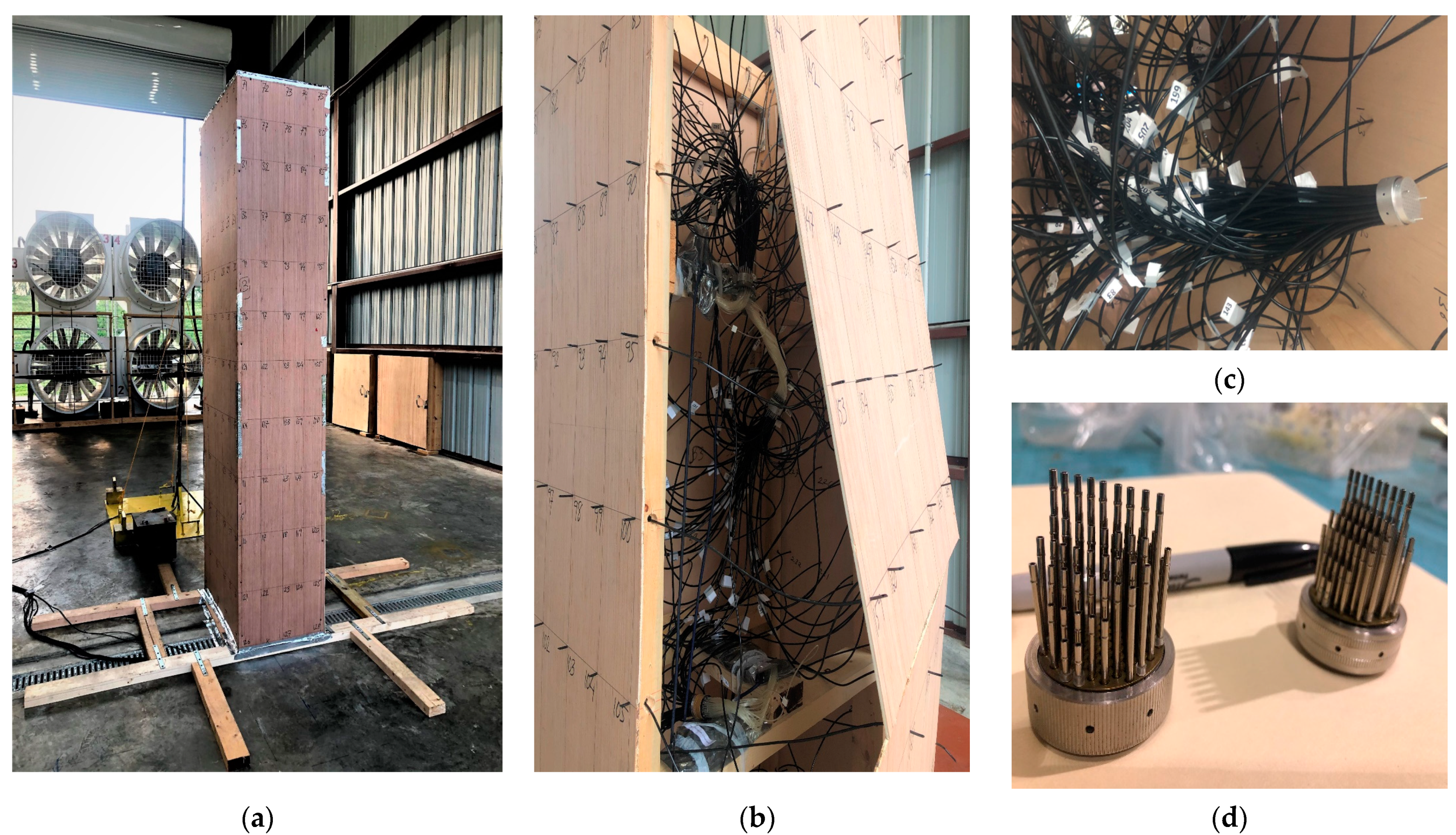
6. Study 3: Large-Scale Open-Jet Testing for Cladding Design in High-Rise Buildings

The construction of high-rise buildings aligns with sustainability tenets by enabling a greater population density within a confined footprint [23,75,76]. Nevertheless, high-rise edifices are notably susceptible to the influence of wind loads [24]. The prevailing flow pattern hinges on various phenomena, including separation, wake development, and vortex generation. These factors create prominent fluctuations in pressures exerted on the building’s exterior, with the potential for cladding damage and excessive structural responses in both translational and torsional modes [25]. Consequently, comprehensive aerodynamic investigations are imperative for accurate response analysis and informing the design of façades and cladding systems. Given the heightened frequency and intensity of severe wind events in recent years, high-rise buildings have experienced an increase in damage incidents.

6.1. Objectives of the High-Rise Building Study
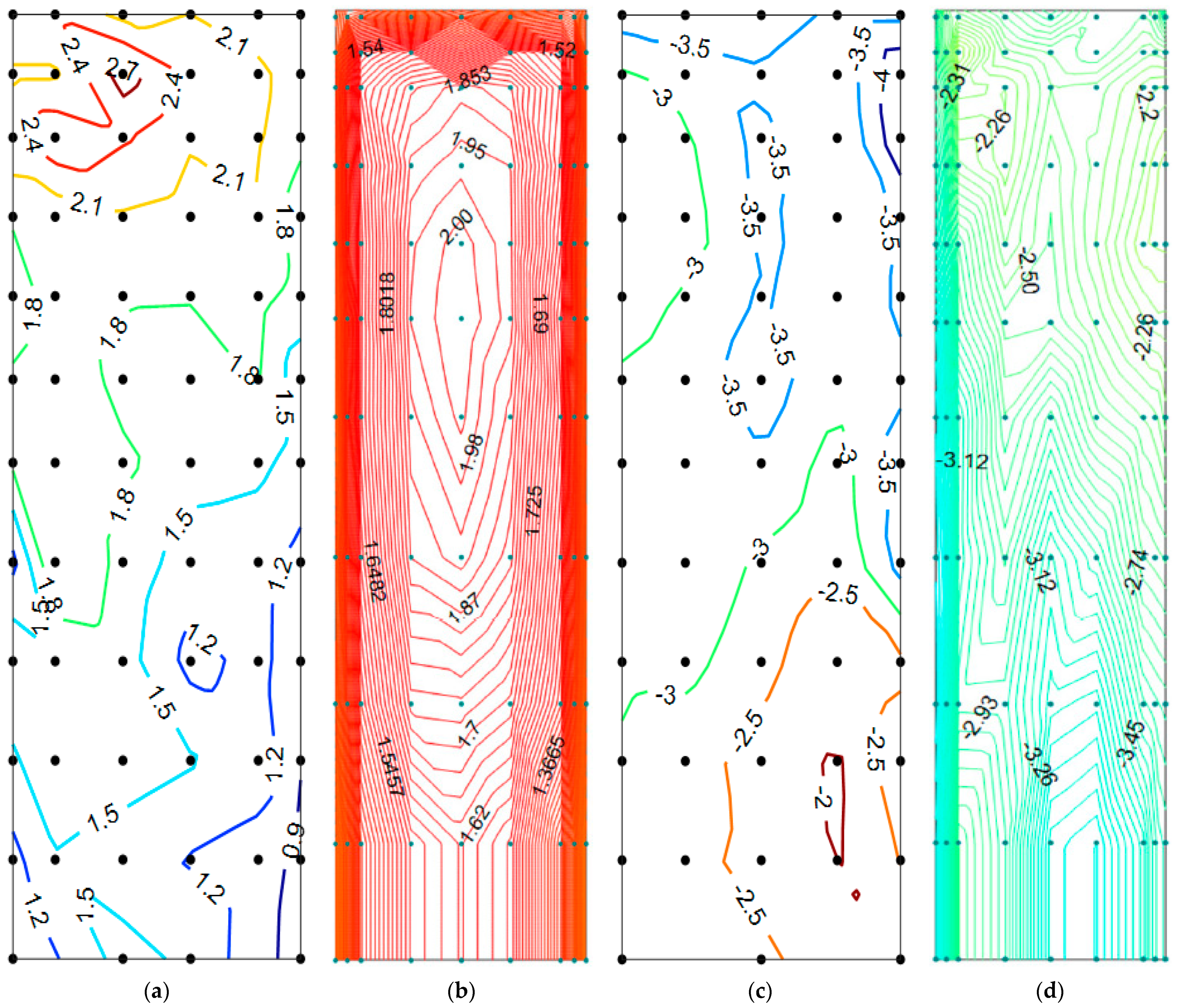
This investigation aimed to precisely reproduce the distribution of wind-induced pressure surrounding a tall building, through experimentation on a large-scale model at a high Reynolds number [57]. The primary objective was the adept design of cladding components, glass, and fenestration for high-rise structures to mitigate damage from severe wind occurrences. Emphasis was placed on comprehending the impacts of aspect ratio and scale effects on pressure magnitude and distribution [57]. The aerodynamic testing encompassed two distinct aspect ratios (width-to-depth ratios of 0.67 and 1.5) to gauge the significance of structural dimensions on wind loading. Comparative analysis of findings from this open-jet testing study with those from a smaller-scale study was conducted, to underscore the criticality of testing at elevated Reynolds numbers. Non-dimensional pressure contours were generated for all facets of the structure. An examination of peak and fluctuating pressures was undertaken to grasp the influence of the Reynolds number on the aerodynamic loads responsible for damage to cladding, glass, and fenestration of tall buildings in the face of extreme winds.
A three-dimensional experimental model, scaled at 1:50, was crafted to delve into the aerodynamic behaviour of the building. The subject of this study is an envisaged timber high-rise slated for construction in Chicago, USA. The dimensional specifications for the full-scale structure are as follows: a height of 121 m, a width of 36 m, and a depth of 24 m [77]. A rigid model of the building was constructed using plywood to custom the outer veneers, while wooden studs formed the skeleton, firmly fastened via screws. Depicted in Figure 11 is the scaled building model, situated within the open-jet test section. Notably, most high-rise edifices examined in wind tunnels are markedly smaller in scale, typically ranging from 1:500 to 1:300 [78,79]. Given the larger scale of this structure, scaling effects on wind load estimations were attenuated, resulting in a more realistic emulation of actual wind flow and associated pressures. The placement of the building, set at twice the height of the open jet from the exit of the blowers, necessitated a specialized configuration at its base to counteract shear and overturning moments. The specifics of the experimental arrangement, model configuration, pneumatic couplings, orientations of wind flow (0 and 90 degrees), and tube layout within the building model are depicted in Figure 11. Five pressure scanners were deployed at five discrete levels [57]. A statistical methodology was employed to obtain minimum and maximum pressures [80]. Although the conventional approach assumes a Gaussian distribution of response, it has been documented that stochastic responses may adhere to a non-Gaussian process. A recent examination has proposed using the Weibull distribution to model peak pressures [81]. Other investigations have concurred that the extreme value type I (Gumbel) distribution accurately represents peak pressures [82,83,84]. Wind pressure data gleaned from open-jet testing were processed using an automated procedure, factoring in the 95th percentile [80]. This methodology yielded peak pressures with minimal susceptibility to record length and sampling frequency compared to observed peaks.

6.2. Scale Effects

To conduct a comparative analysis of pressure distribution on the building, an identical model, albeit at a reduced scale (1:200), was tested at Western University, serving as a reference. This small-scale model exhibited similar height and aspect ratio characteristics.
The peak pressure coefficients showed a prominent disparity between the outcomes of the open-jet and small-scale examinations. Figure 12 delineates the contrast in peak pressure coefficients along the windward and sidewalls of both large and small scale models. On the windward side, the open-jet test recorded a maximum pressure coefficient of 2.7 near the stagnation area (Figure 12a), whereas the small-scale test yielded a corresponding coefficient of two (Figure 12b). The highest peak pressure position differed between both models, with the open-jet test recording the maximum value at a higher elevation.
A pivotal distinction between the two assessments arises in the peak negative pressure on the sidewall. The large-scale model showed a peak pressure coefficient of −4, in contrast to the smaller model, which recorded a coefficient of −3.45. Notably, the magnitude and positioning of peak pressures on the sidewall differed from the small-scale model. This variance between the small- and large-scale results may be attributed to an elevated Reynolds number with complete turbulence in the open-jet scenario. These pivotal flow parameters constituted the primary contributors to discrepancies across various wind tunnel experiments.
As illustrated in Figure 12, the minimum pressure coefficients were situated in the lower portion of the smaller model. In contrast, in the larger model, these coefficients were located in the upper section of the structure. This disparity may lead to an overestimation of pressures in the lower segment and an underestimation in the upper part of the building. Specifically, the smaller model’s upper sidewall section exhibited a minimum pressure coefficient of approximately −2.5. In contrast, the larger model measured around −4, signifying a substantial deviation between the open-jet testing and the wall-bounded test at a smaller scale.

7. Discussion of Results

7.1. Aerodynamics of Low-Rise Building (Study 1)

The paper discussed the aerodynamics of low-rise buildings, emphasizing the role of turbulence in generating peak pressures and separation in the shear layer. Traditional wind tunnel testing has limitations in generating large-scale turbulence at high Reynolds numbers. The increase in large-scale turbulence content in incident flow leads to higher peak pressures but replicating this in testing is challenging due to limitations in turbulence production. Modern tools like the LSU WISE open-jet testing facility can address these challenges, allowing for large-scale testing.
In the literature, partial turbulence simulation has been used as a workaround for compensating for the lack of turbulence in large-scale testing. As demonstrated in Figure 6 of Azzi et al. [59], the flow lacks large-scale turbulence. Neglection of actual flow turbulence contradicts the fundamental understanding of aerodynamics and fluid mechanics. Turbulence is essential for understanding and optimizing the performance of various systems [61]. However, the turbulence generated by the LSU WISE open-jet system conforms to theoretical formulations, encompassing both small- and large-scale components [42]. This discovery carries significant implications for bluff body aerodynamics. A crucial experiment involving a large-scale cubic building model conducted at the LSU open-jet facility at a higher Reynolds number highlighted the importance of such testing for obtaining realistic peak pressures. Additional open-jet test results on the Texas Tech University (TTU) building model mimic field measurements. These additional findings will appear in a separate paper.

7.2. Aerodynamics of a Low-Rise Building with Photovoltaic Panels (Study 2)

The second study investigated the impact of PV panels on wind-induced forces and the security of underlying components in gable-roofed buildings. ASCE 7-16 and 7-22 guidelines mandate the simultaneous application of wind loads for both the bare roof and the solar panels, excluding areas covered by the panels’ plan projection [73,74]. When the solar panel wind pressure is lower than Zone 1 pressures for the bare roof, reduced wind-induced forces are expected on the components and cladding beneath the panels.
ASCE 7-16 underestimates the benefits of solar panels compared to this study’s findings. However, ASCE 7-22 aligns with the current study. Solar panels provide enhanced protection for underlying components and act as a physical barrier against the potential lift or detachment of elements like shingles. Trims are recommended for roof-mounted solar arrays, with the study emphasizing the need for further research to refine standards and assess long-term performance effects. The solar panel study is poised to furnish prescriptive guidelines for superlative practices in robust roof-mounted PV systems, ensuring their steadfastness and durability amid extreme weather events. It aspires to contribute to advancing more efficacious design criteria and regulatory frameworks for these systems.
In addition to wind loads, other factors impacting solar panel functionality should be considered. The response surface methodology (RSM) optimization of waste materials as reflectors for bifacial PV modules demonstrates a significant improvement in energy output [87]. Ganesan et al. [88] proposed installing upside-down modules to address potential defects. Murugesan et al. [89] eradicated the necessity of reconfiguration in PV arrays to improve the overall performance in the presence of partial shading and faults [90]. Walters et al. [91] highlighted seismic considerations and assessment methodologies for isolated rooftop PV arrays, emphasizing their potential in mitigating building base shear while addressing concerns about potential movement induced by seismic and wind forces. Vibrations can adversely affect buildings [92]. Integrating solar panels with buildings can also serve as tuned mass dampers, providing additional seismic mitigation and vibration control [24].

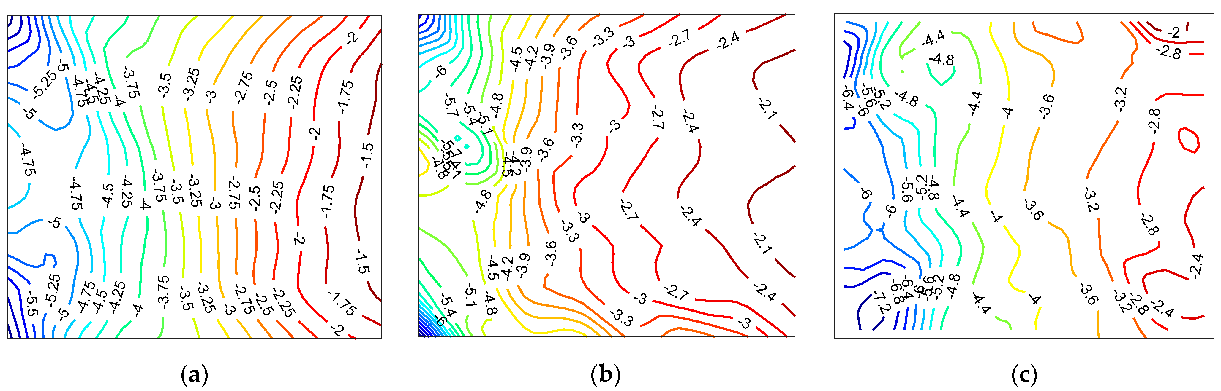
7.3. Aerodynamics of High-Rise Buildings (Study 3)

It has perennially posed a formidable challenge to accurately predict wind-induced pressures and loads on full-scale edifices through small-scale testing. This predicament arises from the contradictions in Reynolds numbers and the dearth of large-scale turbulence emulation. Empirical evidence attests that testing at elevated Reynolds numbers elicits augmented pressures compared to small-scale wind testing [27]. Prior endeavours examining buildings of akin configuration, scaled at 1:200, proved inadequate in elucidating the intricacies of pressure distribution across their surfaces [85,86]. Experimentation with low-rise structures at higher Reynolds numbers corroborates the profound influence of its effects on peak pressures [27].
Wall-bounded small-scale testing of tall buildings conventionally operates within the Reynolds number range of Re ≈ 5–6 × 10⁴ [93]. The current investigation, however, conducted aerodynamic testing at a markedly amplified Reynolds number of Re ≈ 1 × 10⁶, signifying a substantial departure from conventional wind tunnel practice. The intricate mechanisms underlying real-world structural damage are multifold. As the findings corroborate, upper-floor cladding sustains damage due to the imposition of heightened wind loads. The elevated peak pressures experienced towards the uppermost reaches of the structure align harmoniously with empirical observations of wind-induced damage to cladding elements and components (Figure 13a,b).
Conversely, damage to the lower-floor glass elements can be attributed to projectile debris and other complicated flow separations in the wake of a low-rise building adjacent to the primary tower (Figure 13c). Hurricane Katrina served as a poignant reminder that the primary causes for glass and cladding damage are the confluence of high wind velocities and airborne debris coursing through the urban canyon formed by windward structures [96]. A profusion of gravel, glass fragments, pitted glass surfaces, and sundry debris found both in and affixed to the buildings lend substantial credence to the conjecture that wind-borne debris is the primary cause of damage to glass and cladding. The phenomenon of falling glass, propelled along a downward trajectory, precipitates a cascading effect wherein it causes damage to the glass at lower levels, engendering a compounding impact on the windowpanes below [96].
The outcomes presented in this paper affirms the author’s conjecture that wall-bounded wind testing may underestimate critical loads, leading to cladding failure in tall structures. Furthermore, the data supplements the author’s prior observations, indicating that large-scale open-jet testing of low-rise buildings yields higher pressures in contrast to conventional small-scale investigations. In aggregate, these findings underscore the pivotal role of large-scale open-jet testing as a crucial tool in designing robust structures, both low- and high-rise, capable of withstanding windstorms amidst climate change. The LSU WISE open-jet facility is poised to offer pivotal insights for the decision-making processes of architects, engineers, and policy-makers endeavouring to fortify the resilience of built environments and critical infrastructure in the face of escalating climatic risks.

8. Future Research on Solar Energy Systems

8.1. Harmonizing Photovoltaic Panels with Architectural Aesthetics

Integrating PV panels into building designs poses aesthetic challenges that should be resolved to maintain overall visual harmony. PV panels should be incorporated into the initial design phase rather than added as an afterthought [97,98,99,100]. Architects and builders should carefully consider panel size, shape, and colour to ensure seamless integration [101]. This can be complex, particularly for traditional rectangular panels that may be challenging to customize by size and have limited colour options. Traditional panels can sometimes stand out and detract from the building’s appearance. PV panels can be costly, and buildings often incur additional construction and roof integration expenses, potentially doubling overall costs. However, PV installations reduces a building’s carbon footprint, generate clean energy, and may enhance its architectural allure. Because of their benefits, solar panels have become an integral feature in architectural projects as the demand for sustainable and visually appealing structures grows, and architects and builders can create designs that seamlessly blend functionality with visual appeal.

8.2. Building-Integrated Photovoltaics (BIPV)

Building-integrated photovoltaics (BIPV) constitute an intelligent energy production system where PV panels are seamlessly integrated into various building elements, such as the roof, windows, and facades [102,103,104,105]. Generally, BIPV systems exhibit lower efficiency than conventional solar panels [106]. The lower efficiency is attributed to their purposeful integration with the building’s architecture, which may restrict panel size and orientation. Nevertheless, BIPV systems still yield a substantial energy output, and their efficiency can be enhanced through careful design and placement. Given their integrated nature, BIPV systems necessitate careful consideration during the design phase, as they cannot be easily replaced or altered. It is imperative to strategically position and design the panels to maximize energy generation potential over the building’s lifespan. Additionally, this optimization process can reduce BIPV systems’ payback period, enhancing their long-term cost-effectiveness [107,108,109,110,111].
Cost-related challenges in implementing BIPV systems on low-rise buildings are multifaceted. Firstly, the initial investment for BIPV systems tends to surpass that of conventional solar panels, potentially rendering them economically less feasible for such structures [112,113]. This higher upfront cost is primarily attributed to the need for customized integration, ensuring seamless alignment with the building’s architectural design. However, strategic approaches can be adopted to bolster the economic viability of BIPV. One pivotal tactic involves optimizing the design of BIPV systems, thereby enhancing their energy generation potential. Considerations such as selecting optimal orientation, tilt angle, and panel dimensions to maximize energy yield are essential considerations. Concurrently, cost-effective installation methods can be implemented, employing prefabricated panels and streamlining the installation process. This step not only curtails the installation expenses but also contributes to balancing the higher initial cost associated with BIPV systems. Governmental intervention in the form of incentives and subsidies have proven instrumental in encouraging BIPV adoption in low-rise buildings [114]. These measures, encompassing tax credits, rebates, and grants, defray the initial investment and ultimately render BIPV systems a more financially prudent choice.
The durability and longevity of BIPV systems stand as paramount concerns due to their integral role in a building’s design, rendering them not easily replaceable or modifiable. Several factors influence the lifespan of BIPV systems. Firstly, manufacturing quality plays a pivotal role; employing high-grade materials in their construction enhances resilience to adverse weather conditions and prolongs their functional lifespan [113]. Equally significant is the quality of installation, as subpar execution can result in leaks, potentially causing damage to the panels and diminishing their longevity. Regular maintenance constitutes another vital aspect, encompassing panel cleaning, damage inspections, and timely repairs to ensure sustained functionality. Environmental variables, including temperature, humidity, and UV radiation, influence BIPV systems’ longevity [115,116]. Exposure to extreme weather conditions can expedite panel degradation, reducing their lifespan. In order to maximize energy generation potential and minimize the need for replacement or repair, it is imperative to guarantee the durability and longevity of BIPV systems. While these systems generally have a 20- to 30-year guarantee [117], their operational lifespan can be extended through top-tier materials, careful installation and maintenance, and shielding against harsh environmental conditions.
Local building codes and permitting requirements are pivotal in overseeing the installation, operation, and upkeep of BIPV systems, ensuring their adherence to safety standards and legal authorization for building integration [118]. Factors influencing BIPV installation encompass jurisdiction-specific building codes and regulations, necessitating compliance and acquisition of requisite permits before commencement [119]. Additionally, codes may mandate secure and accessible pathways for system maintenance and repair [120]. Furthermore, structural integrity is imperative, with codes stipulating robust anchoring of BIPV systems and design criteria for roof components to support photovoltaic loads [121].
Shading and obstructions pose considerable challenges to the efficiency of BIPV systems [122]. When a portion of the BIPV system is shaded, it can diminish the overall output, as shaded cells become akin to resistors, reducing system performance, a phenomenon known as the “Christmas light effect” [122]. Additionally, obstructions like trees, buildings, or other structures can exacerbate shading issues, compromising BIPV system efficiency. Several strategies can be implemented to address these challenges. Optimizing the BIPV system design can minimize shading and obstructions by carefully selecting the panels’ location, orientation, and tilt angle and incorporating bypass diodes [123]. Regular monitoring using sensors or software to detect changes in system output due to shading or obstructions is another approach to enhance efficiency. Additionally, routine maintenance can keep panels clean and free from debris, thus averting potential shading issues and identifying and rectifying any system damage or defects [124].

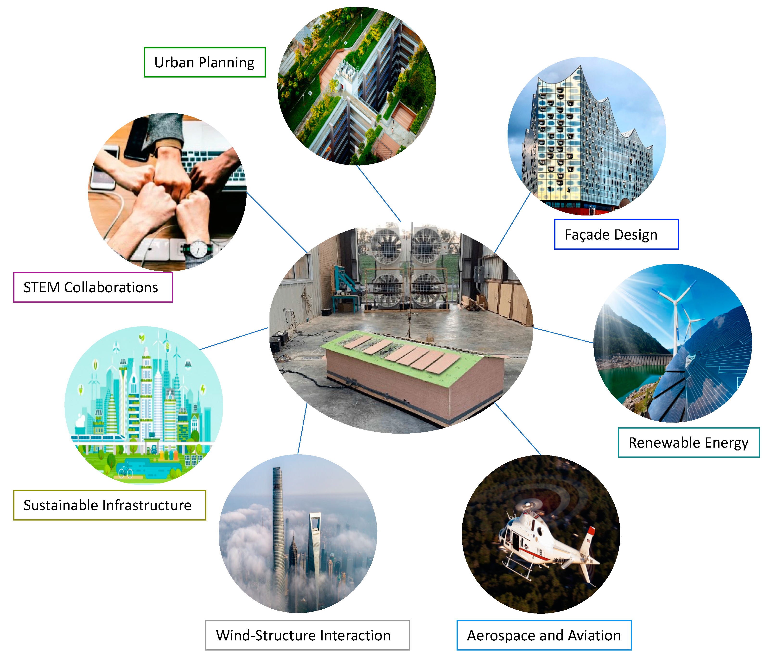
9. LSU WISE Open-Jet Testing Vision: Revolutionizing Wind Engineering

The LSU WISE open-jet testing, a pioneering approach in wind engineering, promises a paradigm shift in structural resilience and design [63]. The facility represents a Mid-Scale Research Infrastructure to address grand challenges and the need for experimental research capabilities in the mid-scale range. This section explores the profound implications of this technology across diverse applications (see Figure 14).

9.1. Optimizing Urban Planning and Green Spaces

Urban environments are increasingly facing the challenges of population growth, urbanization, and the need for sustainable development. The design and layout of cities profoundly impact the well-being of inhabitants and the overall functionality of urban spaces.
One of the primary challenges in urban planning is mitigating the effects of wind on structures, pedestrians, and green spaces. High winds can create uncomfortable and potentially hazardous conditions, limiting the use of parks and outdoor spaces [125]. Additionally, inadequate planning can lead to inefficient energy usage in buildings due to wind-induced pressure differentials [126]. Open-jet testing provides a powerful tool to simulate wind conditions within urban environments accurately. Subjecting models of city layouts to controlled wind flow enables the identification of high-wind areas and the optimization of green spaces and building placements. Wind testing can help identify the most effective building shapes and orientations for maximizing natural ventilation [127,128]. This enhances cities’ liveability and supports energy-efficient architectural designs [129,130]. Integrating wind flow and pressure data, as well as aerodynamic loads obtained from the open-jet testing facility with advanced data science techniques can improve the understanding of wind behavior and its impact on various structures, to assist with Harnessing the Data Revolution for 21st Century Science and Engineering (HDR).

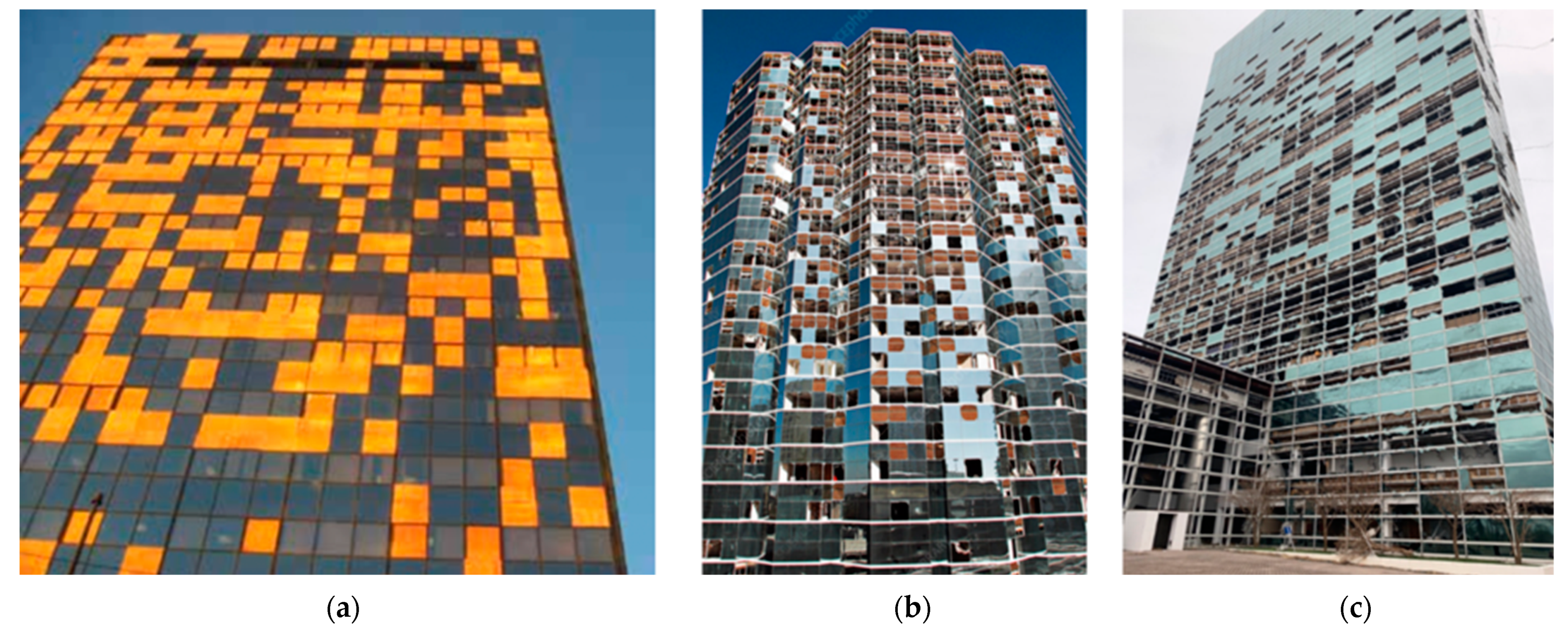
9.2. Innovations in Architectural Façade Design

Architectural facades are a critical element of building design, influencing aesthetics, energy efficiency, and structural integrity [131]. The design of facades has evolved significantly with advancements in materials and construction techniques [132].
Innovations in architectural design are often hindered by the need to balance aesthetics with practical considerations [133]. Facades must be visually appealing and provide insulation, structural support, and protection against environmental factors such as wind, rain, and temperature fluctuations [134,135].
Open-jet testing offers a dynamic approach to assessing large-scale architectural facades under high Reynolds numbers and complete turbulence. Researchers can evaluate how different designs respond to varying windstorms by subjecting scale models to controlled conditions. This allows for the refinement of facade systems to enhance their aesthetic appeal and performance, and, hence, open-jet testing can lead to the development of more resilient facade materials and configurations, ensuring that buildings can withstand extreme weather events.

9.3. Revolutionizing Offshore Wind Energy

Offshore wind energy represents a critical component of the transition to renewable energy sources [136,137]. Offshore wind farms harness the vast energy potential of the open sea, providing a sustainable alternative to traditional fossil fuels [138].
Designing and deploying offshore wind energy platforms is complex [139]. These structures must withstand harsh marine conditions, including high winds, waves, and corrosive saltwater [140,141]. Ensuring these platforms’ stability and longevity is essential for offshore wind energy’s viability.
Open-jet testing plays a pivotal role in advancing offshore wind energy technology. Researchers can assess their structural integrity and dynamic response by subjecting scale models of wind energy platforms to physical wind flow and simulated surge and waves (hardware in the loop [142]). This enables the refinement of designs to withstand the challenging marine environment, as open-jet testing can facilitate the optimization of platform configurations for maximum energy extraction, contributing to the overall efficiency of offshore wind farms. Besides, employing the facility’s capabilities to study the impact of high-speed winds on Arctic infrastructure, such as energy platforms and buildings, can enhance their resilience in the face of changing Arctic (Navigating the New Arctic (NNA)).

9.4. Advancing Aerospace and Aviation Safety

Aerospace and aviation industries are at the forefront of technological innovation, constantly striving for enhanced safety, efficiency, and performance in aircraft design and operation [143]. Aerospace engineers face the formidable task of designing aircraft that can navigate various environmental conditions, including turbulent winds, sudden gusts, and other aerodynamic challenges [144]. Ensuring the safety of passengers and crew is paramount, requiring careful design and testing processes [145].
Open-jet testing represents a transformative tool for aerospace and aviation safety. Researchers can simulate real-world flight conditions by subjecting scale models of aircraft to controlled wind flows. This allows for a comprehensive evaluation of aerodynamic performance, stability, and response to various wind scenarios. The insights gained from open-jet testing can directly contribute to the refinement of aircraft designs, leading to enhanced safety measures that support the development of innovative wing profiles and control systems that optimize performance under dynamic wind conditions. Furthermore, open-jet testing can aid in validating the advanced computational models used in aerospace simulations, to ensure that computational predictions align with empirical data, bolstering confidence in virtual testing procedures. By leveraging the potential of open-jet testing, the aerospace and aviation industries can continue to push boundaries in safety and performance, ultimately leading to safer and more efficient air travel.

9.5. Bridging the Gap in Wind–Structure Interaction Research

The interaction between wind forces and structures is a fundamental aspect of engineering [146,147]. Understanding and accurately predicting this interaction is crucial for designing resilient buildings, bridges, wind turbines, power transmission lines, and other types of critical infrastructure [148].
The dynamic nature of wind makes it a formidable force that structures must contend with [149,150]. Variations in wind speed, direction, and turbulence levels can exert substantial forces on flexible structures [151]. Predicting and mitigating these effects is essential for ensuring structural integrity and safety.
Open-jet testing represents a ground-breaking approach to studying wind–structure interaction. Researchers can replicate real-world conditions by subjecting models to controlled wind flows and precisely measuring the forces exerted on structures. This methodology enables the investigation of how different design elements and configurations influence wind-induced loads. It provides critical data for optimizing structural designs, including shape, materials, and reinforcement. Open-jet testing allows for studying complex scenarios such as vortex shedding and resonance phenomena, which can have significant implications for structural stability. The insights gained from open-jet testing under realistic wind flows at higher Reynolds numbers have the potential to revolutionize wind engineering practices, leading to more robust and resilient infrastructure. By bridging the gap in wind–structure interaction research through advanced open-jet testing, engineers can design structures that meet safety standards and withstand the challenges posed by dynamic environmental conditions. The facility’s wind testing capabilities can be leveraged to study the impact of wind forces on nature-based solutions for living organisms and ecosystems, contributing to the understanding of the rules governing the interaction between wind and life (Understanding the Rules of Life).

9.6. Empowering Sustainable Infrastructure Development

Sustainable infrastructure is at the forefront of global efforts to combat climate change and promote environmental stewardship [152,153]. It encompasses designing and constructing resilient, low-impact structures that harmonise with the natural environment [154,155].
The challenges in sustainable infrastructure development are multi-faceted [156]. These include the need for structures to withstand increasingly severe weather events, reduce their energy consumption, and minimize their environmental impact [157]. Achieving these goals requires innovative approaches and technologies.
Open-jet testing emerges as a linchpin in the quest for sustainable infrastructure. By subjecting scale models to realistic wind conditions, researchers can evaluate the performance of sustainable design features, such as green roofs, wind turbines, energy-efficient building materials, and nature-based solutions for coastal restoration. This methodology provides critical data on how these elements interact with wind forces, allowing for the refinement and optimization of sustainable design strategies. For instance, open-jet testing can inform the placement and orientation of renewable energy systems to maximize their efficiency and resilience to wind loads. Furthermore, open-jet testing contributes to developing materials and construction techniques that enhance infrastructure’s durability and environmental compatibility. This includes advances in eco-friendly building materials and techniques for minimizing the environmental footprint of construction projects. Research at the open-jet facility can contribute to the design of new technologies that improve the safety and performance of buildings, aviation, and other types of infrastructure under extreme wind conditions, thereby enhancing the human-technology relationship in the context of wind engineering, to meet the Future of Work at the Human-Technology Frontier (FW-HTF) challenge.

9.7. Fostering Interdisciplinary Research Collaborations

Interdisciplinary collaboration lies at the heart of innovation and progress in engineering and related fields [158]. It brings together experts from various disciplines to tackle complex challenges and develop holistic solutions [159,160].
Traditionally, engineering disciplines have operated within their silos, limiting the exchange of knowledge and hindering the development of comprehensive solutions. Many complex challenges, such as climate change mitigation and sustainable infrastructure, require a multidisciplinary approach [161,162,163].
Open-jet testing serves as a catalyst for fostering interdisciplinary research collaborations. Its versatile application spans engineering disciplines, architecture, environmental science, and beyond. Researchers from diverse backgrounds can leverage open-jet testing to study complex interactions between wind forces and structures, gaining insights that inform their respective fields. For example, architects can work alongside engineers to optimize building designs, while environmental scientists can assess the impact of wind on natural ecosystems. Additionally, interdisciplinary research collaborations facilitated by open-jet testing have the potential to drive innovation in education, as students are exposed to a broader range of expertise and perspectives. The integration of open-jet testing into interdisciplinary research endeavours heralds a new era of holistic problem-solving, where the collective intelligence of experts from diverse fields converges to address some of the most pressing challenges of our time.
The LSU WISE open-jet facility’s unique capabilities, including complete turbulence at high Reynolds numbers, hold immense promise for revolutionizing the field of wind engineering and creating more resilient and sustainable built environments. Its potential applications span critical infrastructure such as low- and high-rise buildings, bridges, solar panels, wind turbines, nature-based solutions for coastal restoration and protection, offshore structures, and more, promising significant economic, societal, and educational impacts in science, technology, engineering, and mathematics (STEM) fields. It offers substantial educational benefits for K-12, undergraduate, and graduate students at a preeminent state university, distinguished as a land-, sea-, and space-grant institution. This initiative is poised to broadly influence wind/structural engineering research and education, fostering feasible investments within the infrastructure sector. Ultimately, this will culminate in establishing more robust and sustainable communities, promoting economic advancement, addressing grand challenges, and elevating the overall quality of life.

10. Conclusions

Addressing the challenge of accurately reproducing wind effects on buildings, particularly in wall-bounded and small-scale scenarios, hinges on overcoming turbulence modelling limitations, especially in replicating the low-frequency segment of the velocity spectrum. Recent advancements in aerodynamic testing, particularly the adoption of techniques like open-jet testing, present a promising solution. Notably, exploring larger models at higher Reynolds numbers in open-jet testing has been instrumental in addressing scaling concerns. However, turbulence is fundamental for the understanding of aerodynamics, as well as for optimizing the performance of various systems.
The LSU WISE open-jet facility distinguishes itself from traditional wall-bounded wind tunnels and other wind testing facilities. It enables the production of complete turbulence at a large scale, eliminating the need for post-processing to rectify turbulence deficiencies observed in partial turbulence simulation methods [51]. This discovery holds significant implications in wind engineering and unsteady aerodynamics.
Post-analysis of severe wind event damage has demonstrated a significant reduction in damage for roofs equipped with solar panels. Integrating solar panels with gable-roofed buildings may not require additional structural reinforcement. The overall main force-resisting system experienced reductions in wind uplift forces ranging from 45 to 63%, contingent on configuration and wind direction angle. Considering panel size, shape, and colour from the initial design phase is crucial when incorporating PV solar panels into building designs. This ensures seamless integration with the building’s exterior, enhancing architectural appeal while reducing the building’s carbon footprint.
While building-integrated photovoltaics (BIPV) may entail higher upfront costs, they offer distinct advantages, including design flexibility and aesthetic appeal. Strategic interventions such as design optimization, cost-effective installation methods, and governmental incentives can bolster the economic viability of BIPV systems.
Contrary to the longstanding belief that wind loads on structures with sharp corners are insensitive to Reynolds numbers, the findings challenge this notion. Open-jet testing produced higher peak pressures than small-scale, wall-bounded wind tests, providing real-world justification for actual damage in high-rise buildings due to high pressures on cladding. These results validate the author’s hypothesis regarding the potential underestimation of peak loads, leading to cladding failures in high-rise buildings. They also reinforce earlier findings, underscoring the superiority of large-scale open-jet testing over conventional wind tunnel assessments.
The LSU WISE open-jet facility’s unique capabilities, including complete turbulence at high Reynolds numbers, hold immense promise for revolutionizing the field of wind engineering and creating more resilient and sustainable built environments. Its potential applications span critical infrastructure such as low- and high-rise buildings, bridges, solar panels, wind turbines, nature-based solutions for coastal restoration and protection, and more, promising significant economic, societal, and educational impacts in science, technology, engineering, and mathematics (STEM) fields.

Funding

Funding was provided by the Louisiana Board of Regents through the Industrial Ties Research Subprogram (ITRS) [award number: LEQSF(2022-25)-RD-B-02]. The author also acknowledges support from the LSU Institute for Energy Innovation [Research for Energy Innovation 2023-I (Phase I)]. Additional support was obtained through collaborative efforts with Solar Alternatives Inc., PosiGen, and the Gulf States Renewable Energy Industry Association (GSREIA). The opinions expressed in this work solely represent those of the author and do not necessarily reflect the views of the sponsoring entities.

Institutional Review Board Statement

Not applicable.

Informed Consent Statement

Not applicable.

Data Availability Statement

Not applicable.

Acknowledgments

The author wishes to express appreciation to the dedicated cohort of students who have contributed to the research endeavours at the LSU WISE research lab for over a decade. Thanks to E. Rone [58], S. Chapain [57], F. Khaled and R. Clancy [63].

Conflicts of Interest

The author declares no conflict of interest. The funders had no role in the study’s design, in the collection, analyses, or interpretation of data, in the writing of the manuscript, or in the decision to publish the results.

References

  1. Collins, J.M.; Walsh, K. Hurricanes and Climate Change; Springer: New York, NY, USA, 2017; Volume 3. [Google Scholar] [CrossRef]
  2. Baptiste, N. Here’s What We Know about Global Warming and Hurricanes. Mother Jones 2017. Available online: https://www.motherjones.com/environment/2017/08/heres-what-we-know-about-global-warming-and-hurricanes/ (accessed on 14 November 2023).
  3. Al-Chalabi, R.; Elshaer, A. Aerodynamic mitigation of low-rise building with complex roof geometry. Front. Built Environ. 2023, 9, 1200383. [Google Scholar] [CrossRef]
  4. Knutson, T.R.; McBride, J.L.; Chan, J.; Emanuel, K.; Holland, G.; Landsea, C.; Held, I.; Kossin, J.P.; Srivastava, A.K.; Sugi, M. Tropical cyclones and climate change. Nat. Geosci. 2010, 3, 157–163. [Google Scholar] [CrossRef]
  5. Mann, M.E.; Emanuel, K.A. Atlantic hurricane trends linked to climate change. Eos Trans. Am. Geophys. Union 2006, 87, 233–241. [Google Scholar] [CrossRef]
  6. Simiu, E. Design of Buildings for Wind: A Guide for ASCE 7-10 Standard Users and Designers of Special Structures, 2nd ed.; John Wiley & Sons, Inc.: Hoboken, NJ, USA, 2011. [Google Scholar] [CrossRef]
  7. Guo, D.; Jiang, S.; Zou, Y.; He, X.; Liu, Q. Parametric Study on the Aerodynamic Characteristics of Wind Guide Barriers for a Train–Bridge System. Appl. Sci. 2023, 13, 9058. [Google Scholar] [CrossRef]
  8. Zhang, Y.; Ke, P.; Hong, P. Aerodynamic Drag Reduction Analysis of Race Walking Formations Based on CFD Numerical Simulations and Wind Tunnel Experiments. Appl. Sci. 2023, 13, 10604. [Google Scholar] [CrossRef]
  9. Yao, G.; Chen, Y.; Yang, Y.; Zheng, Y.; Wu, L.; Du, H. Research on Mechanism of Vortex-Induced Vibration Railing Effect of Double-Deck Large-Span Suspension Bridge. Appl. Sci. 2023, 13, 9314. [Google Scholar] [CrossRef]
  10. Holmes, J.D. Wind Loading of Structures, 3rd ed.; CRC Press: London, UK, 2015. [Google Scholar]
  11. Chen, X.; Zhou, N. Equivalent static wind loads on low-rise buildings based on full-scale pressure measurements. Eng. Struct. 2007, 29, 2563–2575. [Google Scholar] [CrossRef]
  12. Blessing, C.; Chowdhury, A.G.; Lin, J.; Huang, P. Full-scale validation of vortex suppression techniques for mitigation of roof uplift. Eng. Struct. 2009, 31, 2936–2946. [Google Scholar] [CrossRef]
  13. Khanduri, A.C.; Stathopoulos, T.; Bédard, C. Wind-induced interference effects on buildings—A review of the state-of-the-art. Eng. Struct. 1998, 20, 617–630. [Google Scholar] [CrossRef]
  14. Aly, A.M.; Bitsuamlak, G.T.; Chowdhury, A.G. Full-scale aerodynamic testing of a loose concrete roof paver system. Eng. Struct. 2012, 44, 260–270. [Google Scholar] [CrossRef]
  15. Kareem, A. Wind induced torsional loads on structures. Eng. Struct. 1981, 3, 85–86. [Google Scholar] [CrossRef]
  16. Ricci, M.; Patruno, L.; de Miranda, S. Wind loads and structural response: Benchmarking LES on a low-rise building. Eng. Struct. 2017, 144, 26–42. [Google Scholar] [CrossRef]
  17. Belloli, M.; Rosa, L.; Zasso, A. Wind loads on a high slender tower: Numerical and experimental comparison. Eng. Struct. 2014, 68, 24–32. [Google Scholar] [CrossRef]
  18. Poitevin, A.; Natalini, B.; Godoy, L.A. Pressures on open canopy structures with parapets under wind loading. Eng. Struct. 2013, 56, 850–867. [Google Scholar] [CrossRef]
  19. He, J.; Pan, F.; Cai, C. A review of wood-frame low-rise building performance study under hurricane winds. Eng. Struct. 2017, 141, 512–529. [Google Scholar] [CrossRef]
  20. Stathopoulos, T. Wind loads on low-rise buildings: A review of the state of the art. Eng. Struct. 1984, 6, 119–135. [Google Scholar] [CrossRef]
  21. FEMA. Summary Report on Building Performance: Hurricane Katrina 2005; FEMA: Washington, DC, USA, 2006. [Google Scholar]
  22. FEMA. Hurricane Sandy in New Jersey and New York; FEMA: Washington, DC, USA, 2013. Available online: https://www.fema.gov/media-library-data/1386850803857-025eb299df32c6782fdcbb6f69b35b13/Combined_Sandy_MAT_Report_508post.pdf (accessed on 14 November 2023).
  23. Aboulnaga, M.M. High-Rise Buildings in Context of Sustainability; Urban Metaphors of Greater Cairo, Egypt: A Case Study on Sustainability and Strategic Environmental Assessment. In Sustainable High Rise Buildings in Urban Zones; Sayigh, A., Ed.; Springer: Berlin/Heidelberg, Germany, 2017; pp. 163–217. [Google Scholar] [CrossRef]
  24. Taha, A.E. Vibration Control of a Tall Benchmark Building under Wind and Earthquake Excitation. Pract. Period. Struct. Des. Constr. 2021, 26, 4021005. [Google Scholar] [CrossRef]
  25. Mendis, P.; Ngo, T.; Haritos, N.; Hira, A.; Samali, B.; Cheung, J. Wind loading on tall buildings. Electron. J. Struct. Eng. 2007, 3, 41–54. [Google Scholar] [CrossRef]
  26. Tieleman, H.W. Wind tunnel simulation of wind loading on low-rise structures: A review. J. Wind Eng. Ind. Aerodyn. 2003, 91, 1627–1649. [Google Scholar] [CrossRef]
  27. Aly, A.M.; Khaled, F.; Gol-Zaroudi, H. Aerodynamics of Low-Rise Buildings: Challenges and Recent Advances in Experimental and Computational Methods. In Aerodynamics; IntechOpen: London, UK, 2020; pp. 1–22. [Google Scholar] [CrossRef]
  28. National Research Council. Review of the Need for a Large-Scale Test Facility for Research on the Effects of Extreme Winds on Structures; The National Academies Press: Washington, DC, USA, 1999. [Google Scholar]
  29. NOAA Office for Coastal Management. Hurricane Costs. 2021. Available online: https://coast.noaa.gov/states/fast-facts/hurricane-costs.html (accessed on 11 May 2021).
  30. NHC Public Affair. Costliest U.S. Tropical Cyclones Tables Updated. 2018. Available online: https://www.nhc.noaa.gov/news/UpdatedCostliest.pdf (accessed on 14 November 2023).
  31. Blake, E.S.; Zelinsky, D.A. National Hurricane Center Tropical Cyclone Report: Hurricane Harvey. 2018. Available online: https://www.nhc.noaa.gov/data/tcr/AL092017_Harvey.pdf (accessed on 14 November 2023).
  32. Cangialosi, J.P.; Latto, A.S.; Berg, R. National Hurricane Center Tropical Cyclone Report: Hurricane Irma. 2018. Available online: https://www.nhc.noaa.gov/data/tcr/AL112017_Irma.pdf (accessed on 14 November 2023).
  33. Discher, E. Hurricane Laura blows windows out of 22-story tower in Lake Charles. The Advocate. 2020. Available online: https://www.theadvocate.com/baton_rouge/news/weather_traffic/watch-hurricane-laura-blows-windows-out-of-22-story-tower-in-lake-charles-like-swiss/article_e70053b8-e85f-11ea-bbd8-9b5bdabf8207.html (accessed on 14 November 2023).
  34. Aly, A.M.; Whipple, J. Wind Forces on Ground-Mounted Photovoltaic Solar Systems: A Comparative Study. Appl. Sol. Energy 2021, 57, 444–471. [Google Scholar] [CrossRef]
  35. Hoxey, R.P.; Robertson, A.P.; Richardson, G.M.; Short, J.L. Correction of wind-tunnel pressure coefficients for Reynolds number effect. J. Wind Eng. Ind. Aerodyn. 1997, 69–71, 547–555. [Google Scholar] [CrossRef]
  36. Hoxey, R.P.; Reynolds, A.M.; Richardson, G.M.; Robertson, A.P.; Short, J.L. Observations of Reynolds number sensitivity in the separated flow region on a bluff body. J. Wind Eng. Ind. Aerodyn. 1998, 73, 231–249. [Google Scholar] [CrossRef]
  37. Richards, P.J.; Hoxey, R.P. Flow reattachment on the roof of a 6 m cube. J. Wind Eng. Ind. Aerodyn. 2006, 94, 77–99. [Google Scholar] [CrossRef]
  38. Huang, P.; Wang, X.; Gu, M. Field experiments for wind loads on a low-rise building with adjustable pitch. Int. J. Distrib. Sens. Netw. 2012, 2012, 451879. [Google Scholar] [CrossRef]
  39. ASCE7-2010. Minimum Design Loads for Buildings and Other Structures, ASCE Standard, ASCE/SEI 7-10. American Society of Civil Engineers: Reston, VA, USA, 2010.
  40. Augustyn, M.; Barski, M.; Chwał, M.; Stawiarski, A. Experimental and Numerical Estimation of the Aerodynamic Forces Induced by the Wind Acting on a Fast-Erecting Crane. Appl. Sci. 2023, 13, 10826. [Google Scholar] [CrossRef]
  41. Jin, L.; Deng, X.B.; Wang, X.; Zhang, J.; Zeng, W. Review of Mechanisms and Suppression Methods for Low-Frequency Pressure Fluctuations in Open-Jet Wind Tunnels. Appl. Sci. 2023, 13, 10808. [Google Scholar] [CrossRef]
  42. Aly, A.M.; da Fonseca Yousef, N. High Reynolds number aerodynamic testing of a roof with parapet. Eng. Struct. 2021, 234, 112006. [Google Scholar] [CrossRef]
  43. ASCE 49-12. Wind Tunnel Testing for Buildings and Other Structures. American Society of Civil Engineers: Reston, VA, USA, 2012. [CrossRef]
  44. Aly, A.M. Atmospheric boundary-layer simulation for the built environment: Past, present and future. Build. Environ. 2014, 75, 206–221. [Google Scholar] [CrossRef]
  45. Gol-Zaroudi, H.; Aly, A.M. Open-jet boundary-layer processes for aerodynamic testing of low-rise buildings. Wind Struct. 2017, 25, 233–259. [Google Scholar] [CrossRef]
  46. Aly, A.M. On the evaluation of wind loads on solar panels: The scale issue. Sol. Energy 2016, 135, 423–434. [Google Scholar] [CrossRef]
  47. Jafari, A.; Ghanadi, F.; Emes, M.J.; Arjomandi, M.; Cazzolato, B.S. Measurement of unsteady wind loads in a wind tunnel: Scaling of turbulence spectra. J. Wind Eng. Ind. Aerodyn. 2019, 193, 103955. [Google Scholar] [CrossRef]
  48. Holmes, J.D.; Sankaran, R.; Kwok, K.C.S.; Syme, M.J. Eigenvector modes of fluctuating pressures on low-rise building models. J. Wind Eng. Ind. Aerodyn. 1997, 69–71, 697–707. [Google Scholar] [CrossRef]
  49. Richards, P.J.; Hoxey, R.; Connell, B.D.; Lander, D.P. Wind-tunnel modelling of the Silsoe Cube. J. Wind Eng. Ind. Aerodyn. 2007, 95, 1384–1399. [Google Scholar] [CrossRef]
  50. Azzi, Z.; Habte, F.; Elawady, A.; Gan Chowdhury, A.; Moravej, M. Aerodynamic Mitigation of Wind Uplift on Low-Rise Building Roof Using Large-Scale Testing. Front. Built Environ. 2020, 5, 149. [Google Scholar] [CrossRef]
  51. Asghari Mooneghi, M.; Irwin, P.; Gan Chowdhury, A. Partial turbulence simulation method for predicting peak wind loads on small structures and building appurtenances. J. Wind Eng. Ind. Aerodyn. 2016, 157, 47–62. [Google Scholar] [CrossRef]
  52. Simiu, E. Toward a Standard on the Wind Tunnel Method. NIST Tech. Note Number 1655. 2009; 51p. Available online: https://www.itl.nist.gov/div898/winds/pdf_files/NISTTN1655.pdf (accessed on 14 November 2023).
  53. Ho, T.C.E.; Surry, D.; Morrish, D.; Kopp, G.A. The UWO contribution to the NIST aerodynamic database for wind loads on low buildings: Part 1. Archiving format and basic aerodynamic data. J. Wind Eng. Ind. Aerodyn. 2005, 93, 1–30. [Google Scholar] [CrossRef]
  54. Sagaut, P.; Deck, S.; Terracol, M. Multiscale and Multiresolution Approaches in Turbulence, 2nd ed.; World Scientific: London, UK, 2013. [Google Scholar] [CrossRef]
  55. Duthinh, D.; Simiu, E. The use of wind tunnel measurements in building design. Wind Tunnels Exp. Fluid Dyn. Res. 2011, 282–300. [Google Scholar] [CrossRef]
  56. Khaled, M.F.; Aly, A.M. Assessing aerodynamic loads on low-rise buildings considering Reynolds number and turbulence effects: A review. Adv. Aerodyn. 2022, 4, 1–33. [Google Scholar] [CrossRef]
  57. Aly, A.M.; Chapain, S. Large-Scale Open-Jet Testing for Cladding Design in High-Rise Buildings: Higher Peak Pressures Compared to Wind Tunnels. Pract. Period. Struct. Des. Constr. ASCE 2022, 27, 04022016. [Google Scholar] [CrossRef]
  58. Aly, A.M.; Rone, E. Wind loads on a low-rise gable roof with and without solar panels and comparison to design standards. Sustain. Resilient Infrastruct. 2023. [Google Scholar] [CrossRef]
  59. Azzi, Z.; Matus, M.; Elawady, A.; Zisis, I.; Irwin, P.; Gan Chowdhury, A. Aeroelastic Testing of Span-Wire Traffic Signal Systems. Front. Built Environ. 2020, 6, 111. [Google Scholar] [CrossRef]
  60. Aly, A.M.; Gol-Zaroudi, H. Atmospheric boundary layer simulation in a new open-jet facility at LSU: CFD and experimental investigations. Measurement 2017, 110, 121–133. [Google Scholar] [CrossRef]
  61. Lundström, D.; Krus, P. Testing of atmospheric turbulence effects on the performance of micro air vehicles. Int. J. Micro Air Veh. 2012, 4, 133–149. [Google Scholar] [CrossRef]
  62. Aly, A.M.; Chokwitthaya, C.; Poche, R. Retrofitting building roofs with aerodynamic features and solar panels to reduce hurricane damage and enhance eco-friendly energy production. Sustain. Cities Soc. 2017, 35, 581–593. [Google Scholar] [CrossRef]
  63. Aly, A.M.; Khaled, M.F.; Clancy, R. Large-Scale Open-Jet Testing: A new frontier in structural wind Engineering. Eng. Struct. 2022, 266, 114567. [Google Scholar] [CrossRef]
  64. Aly, A.M.; Voyiadjis, G.; Twilley, R. Hurricane Flow Generation at High Reynolds Number for Testing Energy and Coastal Infrastructure. In Louisiana Board of Regents; EPSCoR Enhencement, Award no. LEQSF(2016-17)-ENH-TR-03; Louisiana Board of Regents: Baton Rouge, LA, USA, 2016. [Google Scholar]
  65. SEIA. Solar Market Insight Report 2021 Q3. 2021. Available online: https://www.seia.org/research-resources/solar-market-insight-report-2021-q3 (accessed on 14 November 2023).
  66. FEMA. Mitigation Assessment Team Report Hurricanes Irma and Maria in Puerto Rico. 2018. Available online: https://www.fema.gov/sites/default/files/2020-07/mat-report_hurricane-irma-maria_virgin-islands.pdf (accessed on 14 November 2023).
  67. Gill, A.; Genikomsou, A.S. Reconnaissance of Buildings Impacted by the 2018 Tornadoes in Ottawa, Canada. J. Perform. Constr. Facil. 2020, 34, 04020074. [Google Scholar] [CrossRef]
  68. US Department of Energy. Solar Photovoltaic Systems in Hurricanes and Other Severe Weather. 2018. Available online: https://betterbuildingssolutioncenter.energy.gov/sites/default/files/pv_severe_weather.pdf (accessed on 14 November 2023).
  69. Simsir, C.C.; Jain, A. Wind-Induced Damage to Rooftop Solar Arrays and Roofs. In Proceedings of the Forensic Engineering 2018: Forgoing Forensic Frontiers, Austin, TX, USA, 29 November–2 December 2018; pp. 53–61. [Google Scholar]
  70. Henderson, C.; Huff, T.; Bouton, G. Structural Observations and Tornado Damage Mitigation Concepts: March 2020 Tennessee Tornadoes. Pract. Period. Struct. Des. Constr. 2021, 26, 05021001. [Google Scholar] [CrossRef]
  71. Burgess, C.; Detweiler, S.; Needham, C.; Oudheusden, F. Solar Under Storm Part II: Select Best Practices for Resilient Roof-Mount PV Systems with Hurricane Exposure, Clinton Foundation, FCX Solar, and Rocky Mountain Institute. 2020. Available online: https://nowsolar.files.wordpress.com/2020/05/solar_under_storm_part_two.pdf (accessed on 14 November 2023).
  72. UNIRAC. Solarmount Detail Drawings 2017. pp. 1–17. Available online: https://ressupply.com/documents/unirac/SolarMount_Detail_Drawings.pdf (accessed on 14 November 2023).
  73. ASCE/SEI 7-16. Minimum Design Loads and Associated Criteria for Buildings and Other Structures. American Society of Civil Engineers: Reston, VA, USA, 2017; ISBN 9780784414248.
  74. ASCE/SEI 7-22. ASCE Minimum Design Loads and Associated Criteria for Buildings and Other Structures. American Society of Civil Engineers: Reston, VA, USA, 2022; Electronic Version. Available online: https://ascelibrary.org/doi/book/10.1061/9780784415788 (accessed on 14 November 2023).
  75. Abdelwahab, M.; Ghazal, T.; Nadeem, K.; Aboshosha, H.; Elshaer, A. Performance-based wind design for tall buildings: Review and comparative study. J. Build. Eng. 2023, 68, 106103. [Google Scholar] [CrossRef]
  76. Ronca, P.; Crespi, P.G.; Longarini, N.; Zucca, M.; Zichi, A. Structural analysis for an historical RC tall building restoration. In Proceedings of the Rehabend 2016-Construction Pathology, Rehabilitation Technology and Heritage Management, Burgos, Spain, 24–27 May 2016; pp. 960–967. [Google Scholar]
  77. Porada, B. The Timber Tower Research Project: Re-Imagining the Skyscraper. 2013. Available online: https://www.archdaily.com/384032/the-timber-tower-research-project-re-imagining-the-skyscraper (accessed on 14 November 2023).
  78. Samali, B.; Kwok, K.C.S.; Wood, G.S.; Yang, J.N. Wind Tunnel Tests for Wind-Excited Benchmark Building. J. Eng. Mech. 2004, 130, 447–450. [Google Scholar] [CrossRef]
  79. Cheng, X.; Huang, G.; Yang, Q.; Zhou, X. Influence of Architectural Facades on Wind Pressures and Aerodynamic Forces of Tall Buildings. J. Struct. Eng. 2021, 147, 04020303. [Google Scholar] [CrossRef]
  80. Sadek, F.; Simiu, E. Peak Non-Gaussian Wind Effects for Database-Assisted Low-Rise Building Design. J. Eng. Mech. 2002, 128, 530–539. [Google Scholar] [CrossRef]
  81. Huang, M.F.; Lou, W.; Chan, C.M.; Lin, N.; Pan, X. Peak Distributions and Peak Factors of Wind-Induced Pressure Processes on Tall Buildings. J. Eng. Mech. 2013, 139, 1744–1756. [Google Scholar] [CrossRef]
  82. Yang, Q.; Tian, Y. A model of probability density function of non-Gaussian wind pressure with multiple samples. J. Wind Eng. Ind. Aerodyn. 2015, 140, 67–78. [Google Scholar] [CrossRef]
  83. Feng, S.; Wang, Y.; Xie, Z. Estimating extreme wind pressure for long-span roofs: Sample independence considerations. J. Wind Eng. Ind. Aerodyn. 2020, 205, 104341. [Google Scholar] [CrossRef]
  84. Lou, J.-J.; Peterka, J.A. Extreme Value Analysis of Peak Wind Pressures on Buildings; Department of Civil Engineering, Colorado State University: Fort Collins, CO, USA, 1981; Available online: http://hdl.handle.net/10217/78859 (accessed on 14 November 2023).
  85. Bezabeh, M.A.; Bitsuamlak, G.T.; Popovski, M.; Tesfamariam, S. Probabilistic serviceability-performance assessment of tall mass-timber buildings subjected to stochastic wind loads: Part I—Structural design and wind tunnel testing. J. Wind Eng. Ind. Aerodyn. 2018, 181, 85–103. [Google Scholar] [CrossRef]
  86. Tesfamariam, S.; Bezabeh, M.; Skandalos, K.; Martinez, E.; Dires, S.; Bitsuamlak, G.; Goda, K. Wind and Earthquake Design Framework for Tall Wood-Concrete Hybrid System; The University of British Columbia: Kelowna, BC, Canada, 2019. [Google Scholar]
  87. Thangaraj, H.; David, P.W.; Balachandran, G.B.; Murugesan, P. Experimental study of bifacial photovoltaic module with waste polyvinyl chloride flex and acrylonitrile butadiene styrene road side safety sticker as an alternative reflector: Optimization using response surface methodology. Environ. Sci. Pollut. Res. 2023, 30, 83873–83887. [Google Scholar] [CrossRef]
  88. Ganesan, K.; Winston, D.P.; Nesamalar, J.J.D.; Pravin, M. Output power enhancement of a bifacial solar photovoltaic with upside down installation during module defects. Appl. Energy 2024, 353, 122070. [Google Scholar] [CrossRef]
  89. Murugesan, P.; David, P.W.; Murugesan, P.; Periyasamy, P. Battery based mismatch reduction technique for partial shaded solar PV system. Energy 2023, 272, 127063. [Google Scholar] [CrossRef]
  90. Hariharasudhan, T.; Prince Winston, D.; Palpandian, M.; Pravin, M. A comparative analysis of polycrystalline and bifacial photovoltaic module under various partial shading condition. Energy Convers. Manag. 2022, 270, 116223. [Google Scholar] [CrossRef]
  91. Walters, M.; Berkowitz, R.; Lau, D.; Lee, W.; Baker, J.W. Seismic Considerations and Evaluation Approach for “Isolated” Rooftop PV Arrays. In Proceedings of the SEAOC 2012 Convention Proceedings, Santa Fe, NM, USA, 12–15 September 2012; Available online: https://www.jackwbaker.com/Publications/Walters_et_al_(2012)_Rooftop_PV,_SEAOC.pdf (accessed on 14 November 2023).
  92. Longinow, A.; Mohammadi, J. Effects of Vibrations on Structures: Overview and Case Studies. Pract. Period. Struct. Des. Constr. 2022, 27, 04022049. [Google Scholar] [CrossRef]
  93. Hui, Y.; Yuan, K.; Chen, Z.; Yang, Q. Characteristics of aerodynamic forces on high-rise buildings with various façade appurtenances. J. Wind Eng. Ind. Aerodyn. 2019, 191, 76–90. [Google Scholar] [CrossRef]
  94. Mejorin, A.; Trabucco, D.; Stelzer, I. Cyclone-Resistant Façades. Chicago, IL, USA. 2019. Available online: https://store.ctbuh.org/research-reports/223-cyclone-resistant-facades.html (accessed on 14 November 2023).
  95. Jeffrey High Rise Building Damaged by Hurricane Wilma. 2005. Available online: https://images.fineartamerica.com/images/artworkimages/mediumlarge/2/high-rise-building-damaged-by-hurricane-wilma-jeffrey-greenberguigscience-photo-library.jpg (accessed on 7 July 2021).
  96. Bashor, R.; Kareem, A. Performance of Glass/Cladding of High-Rise Buildings in Hurricane Katrina; University of Notre Dame: Notre Dame, IN, USA, 2006; Volume 1, Available online: https://www3.nd.edu/~nathaz/documents/Katrina_AAWE_9-21.pdf (accessed on 14 November 2023).
  97. Sánchez-Pantoja, N.; Vidal, R.; Pastor, M.C. Aesthetic impact of solar energy systems. Renew. Sustain. Energy Rev. 2018, 98, 227–238. [Google Scholar] [CrossRef]
  98. Awuku, S.A.; Bennadji, A.; Muhammad-Sukki, F.; Sellami, N. Myth or gold? The power of aesthetics in the adoption of building integrated photovoltaics (BIPVs). Energy Nexus 2021, 4, 100021. [Google Scholar] [CrossRef]
  99. Polo López, C.S.; Frontini, F. Energy efficiency and renewable solar energy integration in heritage historic buildings. Energy Procedia 2014, 48, 1493–1502. [Google Scholar] [CrossRef]
  100. Basher, M.K.; Nur-E-Alam, M.; Rahman, M.M.; Alameh, K.; Hinckley, S. Aesthetically Appealing Building Integrated Photovoltaic Systems for Net-Zero Energy Buildings. Current Status, Challenges, and Future Developments—A Review. Buildings 2023, 13, 863. [Google Scholar] [CrossRef]
  101. Basher, M.K.; Nur-E-alam, M.; Rahman, M.M.; Hinckley, S.; Alameh, K. Design, Development, and Characterization of Highly Efficient Colored Photovoltaic Module for Sustainable Buildings Applications. Sustainability 2022, 14, 4278. [Google Scholar] [CrossRef]
  102. Awuku, S.A.; Muhammad-Sukki, F.; Sellami, N. Building Integrated Photovoltaics—The Journey So Far and Future. Energies 2022, 15, 1802. [Google Scholar] [CrossRef]
  103. Azami, A.; Sevinç, H. The energy performance of building integrated photovoltaics (BIPV) by determination of optimal building envelope. Build. Environ. 2021, 199, 107856. [Google Scholar] [CrossRef]
  104. Jelle, B.P. Building integrated photovoltaics: A concise description of the current state of the art and possible research pathways. Energies 2016, 9, 21. [Google Scholar] [CrossRef]
  105. Ansah, M.K.; Chen, X.; Yang, H. Two-stage lifecycle energy optimization of mid-rise residential buildings with building-integrated photovoltaic and alternative composite façade materials. Buildings 2021, 11, 642. [Google Scholar] [CrossRef]
  106. Liu, B.; Duan, S.; Cai, T. Photovoltaic DC-building-module-based BIPV system-concept and design considerations. IEEE Trans. Power Electron. 2011, 26, 1418–1429. [Google Scholar] [CrossRef]
  107. Jayathissa, P.; Luzzatto, M.; Schmidli, J.; Hofer, J.; Nagy, Z.; Schlueter, A. Optimising building net energy demand with dynamic BIPV shading. Appl. Energy 2017, 202, 726–735. [Google Scholar] [CrossRef]
  108. Paul, D.; Mandal, S.N.; Mukherjee, D.; Bhadra Chaudhuri, S.R. Optimization of significant insolation distribution parameters—A new approach towards BIPV system design. Renew. Energy 2010, 35, 2182–2191. [Google Scholar] [CrossRef]
  109. Khaki, M.; Shahsavar, A.; Khanmohammadi, S.; Salmanzadeh, M. Energy and exergy analysis and multi-objective optimization of an air based building integrated photovoltaic/thermal (BIPV/T) system. Sol. Energy 2017, 158, 380–395. [Google Scholar] [CrossRef]
  110. Yoo, S.H. Optimization of a BIPV system to mitigate greenhouse gas and indoor environment. Sol. Energy 2019, 188, 875–882. [Google Scholar] [CrossRef]
  111. Skandalos, N.; Karamanis, D. An optimization approach to photovoltaic building integration towards low energy buildings in different climate zones. Appl. Energy 2021, 295, 117017. [Google Scholar] [CrossRef]
  112. Gholami, H.; Røstvik, H.N.; Müller-Eie, D. Holistic economic analysis of building integrated photovoltaics (BIPV) system: Case studies evaluation. Energy Build. 2019, 203, 109461. [Google Scholar] [CrossRef]
  113. Gholami, H.; Røstvik, H.N. Economic analysis of BIPV systems as a building envelope material for building skins in Europe. Energy 2020, 204, 117931. [Google Scholar] [CrossRef]
  114. Weerasinghe, R.P.N.P.; Yang, R.J.; Wakefield, R.; Too, E.; Le, T.; Corkish, R.; Chen, S.; Wang, C. Economic viability of building integrated photovoltaics: A review of forty-five (45) non-domestic buildings in twelve (12) western countries. Renew. Sustain. Energy Rev. 2021, 137, 110622. [Google Scholar] [CrossRef]
  115. Zhang, T.; Wang, M.; Yang, H. A review of the energy performance and life-cycle assessment of building-integrated photovoltaic (BIPV) systems. Energies 2018, 11, 3157. [Google Scholar] [CrossRef]
  116. Nwodo, M.N.; Anumba, C.J. A review of life cycle assessment of buildings using a systematic approach. Build. Environ. 2019, 162, 106290. [Google Scholar] [CrossRef]
  117. Debbarma, M.; Sudhakar, K.; Baredar, P. Comparison of BIPV and BIPVT: A review. Resour. Technol. 2017, 3, 263–271. [Google Scholar] [CrossRef]
  118. Bower, W.; DeBlasio, R. Code requirements and standards for installations of photovoltaic systems in the US. Prog. Photovolt. Res. Appl. 1999, 7, 155–164. [Google Scholar] [CrossRef]
  119. Mundada, A.S.; Nilsiam, Y.; Pearce, J.M. A review of technical requirements for plug-and-play solar photovoltaic microinverter systems in the United States. Sol. Energy 2016, 135, 455–470. [Google Scholar] [CrossRef]
  120. Wiles, J. Photovoltaic Power Systems and the 2005 National Electrical Code: Suggested Practices; New Mexico State University: Las Cruces, NM, USA, 2008; ISBN 5056463841. Available online: https://www.altestore.com/store/media/pdfs/photovoltaic_NEC_code_practices2005.pdf (accessed on 14 November 2023).
  121. Eiffert, P.; Kiss, G.J. Building-Integrated Photovoltaic Designs for Commercial and Institutional Structures A Sourcebook for Architects; US Department Energy’s Off Power Technolgy: 2000. Available online: https://www.nrel.gov/docs/fy00osti/25272.pdf (accessed on 14 November 2023).
  122. Lee, C.S.; Lee, H.M.; Choi, M.J.; Yoon, J.H. Performance evaluation and prediction of BIPV systems under partial shading conditions using normalized effciency. Energies 2019, 12, 3777. [Google Scholar] [CrossRef]
  123. Li, Q.; Zhu, L.; Sun, Y.; Lu, L.; Yang, Y. Performance prediction of Building Integrated Photovoltaics under no-shading, shading and masking conditions using a multi-physics model. Energy 2020, 213, 118795. [Google Scholar] [CrossRef]
  124. Strong, S. Building integrated photovoltaics (BIPV). Whole Build. Des. Guid. 2010. Available online: https://www.wbdg.org/resources/building-integrated-photovoltaics-bipv (accessed on 14 November 2023).
  125. Pan, H.Z.; Ou, S.J.; Hsu, C.Y. Exploring the Resilience Park Index from the Perspective of Flood and Wind Disasters. Sustainability 2022, 14, 5560. [Google Scholar] [CrossRef]
  126. Gnatowska, R. Wind-induced pressure loads on buildings in tandem arrangement in urban environment. Environ. Fluid Mech. 2019, 19, 699–718. [Google Scholar] [CrossRef]
  127. Zhao, Y.; Li, R.; Feng, L.; Wu, Y.; Niu, J.; Gao, N. Boundary layer wind tunnel tests of outdoor airflow field around urban buildings: A review of methods and status. Renew. Sustain. Energy Rev. 2022, 167, 112717. [Google Scholar] [CrossRef]
  128. Li, J.; Peng, Y.; Ji, H.; Hu, Y.; Ding, W. A wind tunnel study on the correlation between urban space quantification and pedestrian-level ventilation. Atmosphere 2019, 10, 564. [Google Scholar] [CrossRef]
  129. Du, Y.; Mak, C.M. Improving pedestrian level low wind velocity environment in high-density cities: A general framework and case study. Sustain. Cities Soc. 2018, 42, 314–324. [Google Scholar] [CrossRef]
  130. Plate, E.J. Methods of investigating urban wind fields-physical models. Atmos. Environ. 1999, 33, 3981–3989. [Google Scholar] [CrossRef]
  131. Moghtadernejad, S.; Mirza, M.S.; Chouinard, L.E. Façade Design Stages: Issues and Considerations. J. Archit. Eng. 2019, 25, 04018033. [Google Scholar] [CrossRef]
  132. Knaack, U.; Klein, T.; Bilow, M.; Auer, T. Façades, Principles of Construction; Birkhäuser Verlag AG: Basel, Switzerland, 2007; ISBN 978-3-7643-7961-2. [Google Scholar] [CrossRef]
  133. Larsen, O.P.; Tyas, A. Conceptual Structural Design: Bridging the Gap between Architects and Engineers; Thomas Telford: London, UK, 2003. [Google Scholar] [CrossRef]
  134. Krippner, R.; Musso, F. Basics Facade Apertures; Birkhäuser: Basel, Switzerland, 2017. [Google Scholar] [CrossRef]
  135. Givoni, B. Climate Considerations in Building and Urban Design, 1st ed.; Wiley: Hoboken, NJ, USA, 1998; 480p, ISBN-13: 978-0471291770. [Google Scholar]
  136. Henderson, A.R.; Morgan, C.; Smith, B.; Sørensen, H.C.; Barthelmie, R.J.; Boesmans, B. Offshore wind energy in europe—A review of the state-of-the-art. Wind Energy 2003, 6, 35–52. [Google Scholar] [CrossRef]
  137. Esteban, M.D.; Diez, J.J.; López, J.S.; Negro, V. Why offshore wind energy? Renew. Energy 2011, 36, 444–450. [Google Scholar] [CrossRef]
  138. Fox, B. The offshore grid: The future of America’s offshore wind energy potential. Ecol. Law Q. 2015. [Google Scholar] [CrossRef]
  139. Colmenar-Santos, A.; Perera-Perez, J.; Borge-Diez, D.; Depalacio-Rodríguez, C. Offshore wind energy: A review of the current status, challenges and future development in Spain. Renew. Sustain. Energy Rev. 2016, 64, 1–18. [Google Scholar] [CrossRef]
  140. Karimirad, M. Offshore Energy Structures: For Wind Power Wave Wnergy and Hybrid Marine Platforms; Springer: Cham, Switzerland, 2014; ISBN 9788578110796. [Google Scholar]
  141. Klijnstra, J.; Zhang, X.; van der Putten, S.; Röckmann, C. Technical risks of offshore structures. In Aquaculture Perspective of Multi-Use Sites in the Open Ocean: The Untapped Potential for Marine Resources in the Anthropocene; Springer: Cham, Switzerland, 2017. [Google Scholar] [CrossRef]
  142. Bayati, I.; Belloli, M.; Facchinetti, A. Wind tunnel tests on floating offshore wind turbines: A proposal for hardware-in-the-loop approach to validate numerical codes. Wind Eng. 2013, 37, 557–568. [Google Scholar] [CrossRef]
  143. Seabridge, A.; Moir, I. Design and Development of Aircraft Systems, 3rd ed.; Wiley: Hoboken, NJ, USA, 2019; 400p, ISBN 978-1-119-61151-6. Available online: https://www.wiley.com/en-us/Design+and+Development+of+Aircraft+Systems%2C+3rd+Edition-p-9781119611516 (accessed on 14 November 2023).
  144. Spalart, P.R. Strategies for turbulence modelling and simulations. Int. J. Heat Fluid Flow 2000, 21, 252–263. [Google Scholar] [CrossRef]
  145. Bahr, N.J. System Safety Engineering and Risk Assessment: A Practical Approach, 2nd ed.; CRC Press: Boca Raton, FL, USA, 2014; ISBN 9781466551619. [Google Scholar]
  146. Novak, M.; El Hifnawy, L. Structural response to wind with soil-structure interaction. J. Wind Eng. Ind. Aerodyn. 1988, 28, 329–338. [Google Scholar] [CrossRef]
  147. Huang, Y.; Gu, M.; El Naggar, M.H. Effect of soil-structure interaction on wind-induced responses of supertall buildings with large pile groups. Eng. Struct. 2021, 243, 112557. [Google Scholar] [CrossRef]
  148. Niknamian, S. The Effect of Wind-Soil-Structure Interaction on the Longitudinal Response of High-Rise Buildings (14 December 2017). Available online: https://ssrn.com/abstract=3503732 (accessed on 14 November 2023). [CrossRef]
  149. Bezabeh, M.A.; Bitsuamlak, G.T.; Popovski, M.; Tesfamariam, S. Dynamic Response of Tall Mass-Timber Buildings to Wind Excitation. J. Struct. Eng. 2020, 146, 04020199. [Google Scholar] [CrossRef]
  150. Iancovici, M.; Ionică, G.; Pavel, F.; Moța, F.; Nica, G.B. Nonlinear dynamic response analysis of buildings for wind loads. A new frontier in the structural wind engineering. J. Build. Eng. 2022, 47, 103708. [Google Scholar] [CrossRef]
  151. Wu, Y.; Sun, X.; Shen, S. Computation of wind-structure interaction on tension structures. J. Wind Eng. Ind. Aerodyn. 2008, 96, 2019–2032. [Google Scholar] [CrossRef]
  152. Ayyub, B.M. (Ed.) Committee on Adaptation to a Changing Climate. In Climate-Resilient Infrastructure: Adaptive Design and Risk Management; American Society of Civil Engineers: Reston, VA, USA, 2018; ISBN (print): 9780784415191 ISBN (PDF): 9780784481905; Available online: https://ascelibrary.org/doi/book/10.1061/9780784415191 (accessed on 14 November 2023).
  153. Gasparatos, A.; Ahmed, A.; Naidoo, M.; Karanja, A.; Fukushi, K. Sustainability Challenges in Sub-Saharan Africa I Continental Perspectives and Insights; Springer: Singapore, 2020; ISBN 9789811544576. [Google Scholar]
  154. Helmy, S.E.; Aboulnaga, M.M. Future Cities: The Role of Biomimicry Architecture in Improving Livability in Megacities and Mitigating Climate Change Risks. In Sustainable Ecological Engineering Design: Selected Proceedings from the International Conference of Sustainable Ecological Engineering Design for Society (SEEDS) 2019; Springer International Publishing: Berlin/Heidelberg, Germany, 2020. [Google Scholar] [CrossRef]
  155. EIB. Sustainable infrastructure Overview 2022. Eur Invest Bank 2022. Available online: https://www.eib.org/en/publications/sustainable-infrastructure-overview-2022 (accessed on 14 November 2023).
  156. Behr, C.; Sekyere, E. Challenges and Opportunities in Evaluating Sustainable Infrastructure. (Policy Brief, March). 2017. Available online: http://hdl.handle.net/20.500.11910/11051 (accessed on 14 November 2023).
  157. Boz, M.A.; El-adaway, I.H. Creating a Holistic Systems Framework for Sustainability Assessment of Civil Infrastructure Projects. J. Constr. Eng. Manag. 2015, 141, 04014067. [Google Scholar] [CrossRef]
  158. Kaygan, P. From forming to performing: Team development for enhancing interdisciplinary collaboration between design and engineering students using design thinking. Int. J. Technol. Des. Educ. 2023, 33, 457–478. [Google Scholar] [CrossRef]
  159. Ren, Z.J. The Rewards and Challenges of Interdisciplinary Collaborations. iScience 2019, 20, 575–578. [Google Scholar] [CrossRef]
  160. Winberg, C. Teaching engineering/engineering teaching: Interdisciplinary collaboration and the construction of academic identities. Teach. High. Educ. 2008, 13, 353–367. [Google Scholar] [CrossRef]
  161. Middleton, B.A. Multidisciplinary Approaches to Climate Change Questions. In Wetlands; Springer: Dordrecht, The Netherlands, 2011; pp. 129–136. [Google Scholar] [CrossRef]
  162. Burroughs, W.J.G. Climate Change: A Multidisciplinary Approach, 2nd ed.; Cambridge University Press: Cambridge, UK, 2007; ISBN-10: 9780521690331. [Google Scholar]
  163. Edwards, G.I. Multidisciplinary Approach to Environmental Problems and Sustainability. In Encyclopedia of Sustainability in Higher Education; Springer: Cham, Switzerland, 2019. [Google Scholar] [CrossRef]
Figure 1. Flowchart illustrating the structural organization of the paper, outlining the sequential exploration of small-scale wind testing challenges (Section 2), the introduction of open-jet testing concepts (Section 3), detailed investigation of large-scale open-jet testing on low-rise buildings (Section 4), examination of roof-mounted solar panel resilience (Section 5), exploration of large-scale open-jet testing for cladding design in high-rise buildings (Section 6), discussion of categorized results (Section 7), exploration of future research avenues (Section 8 and Section 9), and synthesis of key findings and implications (Section 10).
Applsci 13 12546 g001
Figure 2. Lack of large-scale turbulence (low frequency turbulence) in wall-bounded laboratory testing: (a) scale 1:300 (the high turbulence flow matches with the target), (b) scale 1:10 (the high turbulence flow does not match with the target), and (c) normalizing the frequency (x-axis) using the flow integral length scale. Using the flow integral length scale to normalize the frequency can be misleading as it conceals the lack of turbulence (an issue common in previous wall-bounded studies).
Applsci 13 12546 g002
Figure 3. Open-jet testing: (a) the central concept, and (b) small-scale open-jet at LSU.
Applsci 13 12546 g003
Figure 4. LSU WISE large-scale testing facility, featuring a test section measuring 4 m by 4 m.
Applsci 13 12546 g004
Figure 5. Large-scale open-jet experimentation conducted at LSU: (a) velocity spectrum and time history at 1 m, and (b) normalized velocity and turbulence profiles.
Applsci 13 12546 g005
Figure 6. Mean pressure coefficients were observed in three distinct test configurations: (a) 1:100 TPU wind tunnel, (b) 1:26 LSU open-jet, and (c) 1:13 LSU open-jet.
Applsci 13 12546 g006
Figure 7. Ninety-fifth percentile minimum pressure coefficients under varying test conditions: (a) in a 1:100 TPU wind tunnel, (b) in a 1:26 LSU open-jet, and (c) in a 1:13 LSU open-jet.
Applsci 13 12546 g007
Figure 8. Roof damage examples with and without solar PV panels: (a) a roof in Puerto Rico, featuring solar PV panels displaying corrosion and insufficient fasteners near the roof edge (red arrow), although the panels prevented further damage; (b) close-up of solar PV panels securing portions of the roof covering (blue arrows show adequate fastening); (c) A roof near Ottawa, Canada, without solar panels, exhibiting extensive tornado-induced damage; and (d) a residence in the same area with PV panels, showing no visible roof damage.
Applsci 13 12546 g008
Figure 9. Aerodynamic test model comprising: (a) a gabled roof integrated with PV panels (Case 2), (b) an active panel equipped with pressure taps affixed onto the roof (tubes precisely aligned with the surface before testing), (c) a PV array model featuring an engineered racking system (Case 3), and (d) panel configuration enhancements implemented for conclusive testing, entailing gap closure and integration of a leading-edge trim (Case 4). The trim was constructed to a 1:7.5 scale, in concordance with the overall model.
Applsci 13 12546 g009
Figure 10. Minimum pressure coefficients were observed for taps 1–110 on the roof surface, maintaining a 0-degree orientation across all four experimental trials. Subfigure (a) delineates the spatial arrangement of the pressure taps (dots) and prevailing wind direction (arrow). Subfigure (b) visually represents the building’s alignment within the open-jet testing facility. Subfigures (c) through (f) present the minimum pressure coefficients corresponding to distinct roof configurations: (c) unadorned roof (Case 1), (d) roof outfitted with panels (Case 2), (e) roof furnished with panels and supporting framework (Case 3), and (f) roof featuring panels, supporting framework, and trim (sans interstices) (Case 4).
Applsci 13 12546 g010
Figure 11. Experimental configuration. In subfigure (a), the test model, scaled geometrically at 1:50, showcases the building’s narrow facade aligned orthogonally to the prevailing wind direction. Subfigure (b) details the model’s internal tube and Scanivalve pressure scanner arrangement. Subfigure (c) exhibits pneumatic tubes with connectors, each appropriately labelled. Subfigure (d) shows 72-port pneumatic connectors. A total of 256 pressure taps were distributed on the outer faces of the high-rise building model.
Applsci 13 12546 g011
Figure 12. Peak pressure coefficients for both large-scale (1:50) and small-scale (1:200) models with a ratio of base width to diameter (B/D) equal to 1.5. Panels (a,b) pertain to the windward sides of the large and small-scale models, respectively, while panels (c,d) correspond to the sidewalls of the large and small-scale models, respectively. The small-scale data has been sourced from references [85,86].
Applsci 13 12546 g012
Figure 13. Repercussions of high-intensity winds on cladding and glass facades of tall structures. Notably, a majority of the structural impairment manifests at elevated altitudes: (a) showcases wind-induced damage on the Colonial Bank building in Miami after Hurricane Wilma (modified from [94]); (b) displays windows of a high-rise office building adversely affected by Hurricane Wilma in Miami, Florida, USA (adapted from [95]); and (c) exhibits the windows of Capitol One Tower post Hurricane Laura’s impact in Lake Charles, Louisiana, USA (adapted from [33]).
Applsci 13 12546 g013
Figure 14. LSU WISE open-jet testing vision: revolutionizing wind engineering to address grand challenges.
Applsci 13 12546 g014
Table 1. Reynolds numbers correspond to varying scales.
Scale 1:100 (TPU WT)1:26 (LSU OJ)1:13 (LSU OJ)
Reynolds number 4.9 10 4 0.34 10 6 0.8 10 6
Table 2. The highest average “net” minimum pressure coefficients for Zone 1 across all test angles. These net pressure coefficients indicate the aggregate force exerted on the structure when subjected to wind-induced loads acting on both the roof and the attached solar panels.
ZoneCase 1Case 2Case 3Case 4
CpAngleCpAngleCpAngleCpAngle
1W−0.8650−0.400 (54%)0−0.478 (45%)0−0.336 (61%)270
1L−0.9060−0.362 (60%)180−0.436 (52%)180−0.335 (63%)270
Disclaimer/Publisher’s Note: The statements, opinions and data contained in all publications are solely those of the individual author(s) and contributor(s) and not of MDPI and/or the editor(s). MDPI and/or the editor(s) disclaim responsibility for any injury to people or property resulting from any ideas, methods, instructions or products referred to in the content.

