1. Introduction
Space antennas find their primary application in satellites, spacecraft, and other similar vehicles, serving as the essential link for two-way communication between these vehicles and ground stations. Functioning as the “ears” or “loudspeakers” of these spacecraft [
1], space antennas have evolved into indispensable components that significantly impact and shape the performance of entire wireless communication systems and, in many cases, the spacecraft as a whole.
The deployable structure of space antennas is a critical component that facilitates antenna deployment and ensures the precision and stability of the antenna surface. The deployable mechanism occupies a substantial portion of the antenna’s overall mass, serving as the structural backbone that directly influences the antenna’s stiffness and natural frequency. Various deployable antenna mechanisms have been developed, including the ring truss type, unit frame type, folding rib type, winding rib type, cable tension type, ring column type, and flexible self-rebound type, among others [
2,
3,
4,
5,
6,
7,
8,
9,
10,
11]. However, the current deployable antenna unfolding methods are mostly fixed and primarily involve circumferential unfolding. Therefore, there is a need for innovative unfolding methods that can expand upon the existing configurations, drawing inspiration from nature’s own mechanisms.
In the natural world, numerous organisms exhibit fascinating unfolding behaviors that are crucial for their survival and functionality. Kishimoto [
12], for instance, meticulously observed the metamorphic unfolding of wing veins in various insect species, which can expand up to forty times larger than their original size. This phenomenon, known as spreading, is achieved by an influx of body fluids into the wing veins. Plants also demonstrate unfolding mechanisms, such as the unrolling of leaves in species like hornbeam and beech [
13], as shown in
Figure 1, among other examples. The earwig’s wing exhibits the highest “folding ratio” in the animal kingdom, expanding its body surface area tenfold, with a central wing joint structure that allows stable folding and unfolding without the need for muscle power. Researchers at ETH Zurich, Switzerland, and Purdue University, USA, have even used 3D printing to create a foldable bionic wing structure, as shown in
Figure 2, which closely resembling an earwig’s wing and is capable of remaining stable when unfolded and folded with a simple touch [
14]. Furthermore, Hoang Vu Phan and Hoon Cheol Park [
15] designed a foldable micro-flapping wing inspired by the hindwing folding action of the rhinoceros beetle during resting and hindwing unfolding during flight, leveraging the beetle’s biological characteristics for passive fluttering. In 1994, Swartz et al. investigated the mechanical properties of the skin of bat wings from different wing structures, studying the unfolding of bat wings [
16], as shown in
Figure 3.
Another striking example of a deployable structure in nature is the flycatcher [
17], which, due to challenging environmental conditions, closes its leaf-like structure to capture insects for nutrients. This process takes around 40 days, and the curvature of the leaf reverses before and after closing to form a typical bistable structure, as illustrated in
Figure 4. A similar mechanism can also be observed in the vocal organs of cicadas.
The number of petals and the curvature factor of the curve have a direct impact on the size of the folded cross-section of film reflectors, as demonstrated in
Figure 5 [
18]. Petal folding also has broader applications, such as in petal satellite antennas, where the transmitting surface consists of sails and steel plates on a rotating substrate, offering advantages like compact storage, lightweight design, and easy deployment [
19].
In addition, the deployment of space antennas faces problems related to hydrodynamics due to turbulence in the space airflow. A new multidimensional artificially characteristic-based (MACB) scheme is presented for the simulation of incompressible viscous flows via heat transfer by Rostamzadeh [
20]. Multidimensional characteristic relations for energy propagation in incompressible flow are derived for the first time.
The expandable structure design based on the principle of bionics is both a new method of designing expandable structures and a new application field of bionics, which requires a certain understanding of the behavioral movements and physiological structures of living creatures. In order to imitate the tail feathers of birds for the bionic design of structures, firstly, the skeletal structure of the tail of birds should be analyzed, and the mechanism of the unfolding movement of the feathers should be analyzed, and then the bionic reference model for the design of the mechanism should be selected.
2. Studies on the Tail Feather Unfolding Behavior of Birds
Stephen M. Gatesy [
21] delves into the evolutionary mechanics of tail feathers in fan-winged and short-tailed birds. Most modern birds possess fan-like tail feathers, consisting of numerous feathers arranged in a staggered pattern. The two central tail feathers are known as the central tail feathers, with the surrounding ones as lateral tail feathers. During flight and landing, these tail feathers play a crucial aerodynamic role, functioning like a rudder and contributing significantly to the bird’s flight capabilities. The unfolding of bird tail feathers is a multi-step process. Initially, the muscles at the tail’s base provide the force to elevate the feathers, transitioning them from a horizontal to a vertical orientation. Subsequently, the lateral tail muscles extend the feathers outward, while the Bulbi rectricium controls the full expansion of the tail feathers, effectively opening the screen.
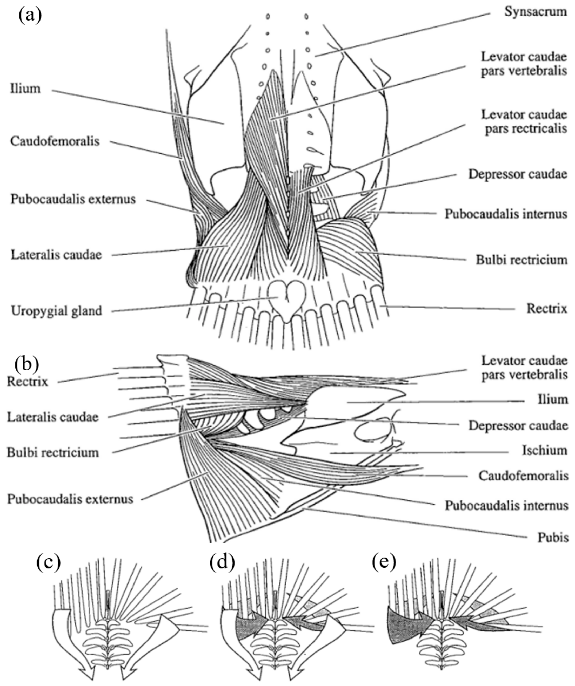
As shown in
Figure 6a, from left to right and from top to bottom, the labels represent the Ilium, Caudofemoralis, Pubocaudalis externus, Lateralis caudae, Uropygial gland, Levator caudaepars vertebralis, levator caudaepars rectricalis, Depressor caudae, Pubocaudalis internus, bulbi rectricium, and Rectrix. As shown in
Figure 6b, from left to right and from top to bottom, the labels are the Rectrix, Lateralis caudae, Bulbi rectricium, Pubocaud alis externus, Levator caudae pars vertebralis, Ilium, Depressor caudae, ischium, Caudofemoralis, pubocaudalis internus, and Pubis.
The Bulbi rectricium plays a crucial role in tail feather movement, encompassing their elevation, depression, and rotation. It should be noted that different portions of the Bulbi rectricium can function autonomously. The left and right muscles are capable of simultaneous dorsal or ventral rotation, as well as rotation in opposing directions. Furthermore, the Bulbi rectricium acts as a regulator for feather clustering. Whether the tail feathers are raised, lowered, swung, or rotated, the Bulbi rectricium coordinates the movements of the Levator caudae pars vertebralis, Depressor caudae, Lateralis caudae descender, and Pubocaudalis.
The central tendon serves two purposes. Firstly, it functions as a ligament that laterally connects and secures the bases of the feathers to the underlying hair follicles; secondly, it serves as a rotational center for the Lateralis caudae when the tail feathers are fully expanded. As depicted in
Figure 6c–e, which illustrates various methods of tail feather unfolding in birds,
Figure 6c proposes that the fan-shaped spreading of feathers primarily relies on the contraction of the caudal lateral muscle. In contrast,
Figure 6d suggests that the unfolding of tail feathers results from the combined action of the Lateralis caudae and the Bulbi rectricium. Lastly,
Figure 6e proposes that the sole cause of feather unfolding is the contraction of the Bulbi rectricium, with no involvement of the Lateralis caudae or other muscles.
Gatesy and Dial (1996) compared the current magnitudes generated by different caudal muscle tissues in pigeons during tail feather unfolding. Their findings indicated that the mean current magnitude produced by the Lateralis caudae during feather unfolding was significantly smaller than that of the Bulbi rectricium. However, they concluded that the Lateralis caudae still plays a substantial role in the unfolding process. As shown in
Figure 7, the contraction of the Lateralis caudae pulls the rudder feather’s base and the entire anterior middle ligament of the central tendon at the caudal helix attachment, forming an arched structure. With the unfolding action, the radius of this arc-shaped ligament gradually decreases, leading to the fan-like expansion of the rudder feather.
In the actual mechanism design, the model in
Figure 6e is not very convenient to implement, so we choose to refer to the model in
Figure 6d for the bionic design of the mechanism.
In practical mechanism design, implementing the model depicted in
Figure 6e may not be particularly feasible. Therefore, we have chosen to refer to the model presented in
Figure 6d for the biomimetic design of the mechanism.
3. Bionic Bird Tail Feather Antenna Configuration Design
In
Figure 8, the bird’s tail feathers exhibit a fan-shaped configuration around the tail heel bone. It is evident from the aforementioned bionic mechanism that the unfurling of the bird’s tail feathers occurs in two stages. In the first stage, the tail heel bone transitions from a horizontal to a vertical orientation, followed by the second stage, in which the feathers attached to the Bulbi rectricium assume a fan-shaped arrangement. Guided by the fundamental principle underlying avian tail movement, the design incorporates a four-rod mechanism.
3.1. Design for the First Unfolding Stage
The process of erecting the tail helix is analogous to the folding motion of the antenna rib itself. The rib and hinge are strategically positioned in a parabolic distribution at the apex to ensure optimal antenna function. The final design of the two-segment antenna rib is illustrated in
Figure 9.
The horizontal alignment of the bird’s tail feathers corresponds to the extended state of the antenna, whereas the vertical alignment of the bird’s tail feathers corresponds to the intermediate unfolded state of the antenna. Adhering to the antenna design concept, an inverse bionic principle is employed for the bionic design. To economize on the antenna space, the second rib of the antenna is further folded from the 90° position to a proximity near the first rib, effectively closing the antenna.
The mechanism parameters of the antenna are given: The first rib of the antenna has a projected length of 0.55 m to the ground, and the second rib of the antenna has a projected length of 1.2 m to the ground. The overall length of the two ribs in the unfolded state is 1.75 m.
In the microgravity environment, only the frictional force and moment of inertia between the components are considered for the drive method. Opting for a rope drive, as opposed to the conventional methods, results in reduced mass and space utilization. A self-locking hinge was engineered to secure the final stage of locking, as depicted in
Figure 10. Connector 1 is affixed to the inner rib, while connector 2 is secured to the outer rib.
3.2. Design for the Second Unfolding Stage
As inferred from the aforementioned bionic mechanism, the second stage of unfurling in the bird’s tail feathers hinges primarily on the extension of the lateral tail muscles and the control exerted by the Bulbi rectriciums. By adhering to the bionic concept, the structure detailed in
Figure 11 was conceived.
To replicate the pulling force exerted by the Bulbi rectricium on the distal end of the rudder feather, a shearing unit comprised of guide rails, a slider, and a linkage mechanism was interposed between two adjacent ribs, as shown in
Figure 12. This arrangement ensures the synchronized movement of the antenna ribs during the unfolding process, while also allowing control over the movement speed and trajectory.
During the process of tail feather unfolding in birds, the principal driving force behind the unfurling of the tail feathers stems from the pull exerted by the tail Lateralis caudae on both ribs, driving structure of ball screw is illustrated in
Figure 13. Following the initial unfolding of the inner ribs to a fixed angle, the two outer ribs come into contact, prompting the locking device affixed to the outer ribs to secure the full extension of the mechanism. The overall mechanism unfolding process is illustrated in
Figure 14,
Figure 15 and
Figure 16.
In the folded state of the antenna, the second segment rib is tightly secured by the firework device and the first segment rib. In the first stage of unfolding, the middle second segment rib is driven by the motor to pivot around the hinge connected to the first segment rib. The self-locking hinge engages upon the completion of unfolding, facilitating the commencement of the second stage of unfolding. During this phase, the ball screw mechanism located at the base gradually propels the two innermost ribs to unfurl, culminating in the full extension of the mechanism through the concerted action of the synchronization mechanism. The locking devices positioned at the terminus of the outer ribs secure their extended position, marking the completion of the second stage of unfolding.
4. Kinematic Analysis
4.1. Kinematic Modeling
Due to the constraint of the synchronous slider mechanism, the 18 ribs have the same angle of spread between ribs at all times. To simplify the analysis, only the position velocity calculation of the driving part components is needed to launch the motion velocity of all ribs, as shown in
Figure 17.
The structure contains six movable members, seven low and zero high subs, according to the formula of degrees of freedom:
The system is calculated as a two-degree-of-freedom system.
F is the degree of freedom of the mechanism; n is the number of moving members of the mechanism; pl is the number of low subs; and ph is the number of high subs.
The driving part of connection position 1 is divided into the driving linkage part and the synchronous mechanism part. First of all, the driving linkage part is analyzed: the auxiliary line is AD, DI, over A for the x-axis vertical line, extended DE; the auxiliary angle is α1, α2, α3, α4, where CD = DE, DE⊥EI.
The connecting rod is divided into two parts: the driving linkage part and the synchronous mechanism part, as shown in
Figure 18 and
Figure 19. Through the solution of the geometric position of each linkage, Equations (2) and (3), respectively, were solved.
The union of Equations (2) and (3) can be solved using
This leads to the following:
where
lxy denotes the distance between the points x and y, and
denotes the angle between the two line segments.
The variation law of (3) is also known, so the expression of time t can be substituted into the angle of rotation of the connecting rod BJ and the displacement of the slider on the antenna rib.
There are variables in the equation:
where the variables are shown in
Table 1.
4.2. Kinematic Simulation
The angular velocity variation is an important indicator of the motion law of the mechanism. The first-order derivative of the position equation can represent the angular velocity and velocity equation of the point, and the first-order derivative of the center-of-mass position equation can represent the velocity variation law of the center of mass.
The center-of-mass coordinate system is established at the center-of-mass position of each linkage, and the displacement vector of the single set of expandable structure is plotted, as shown in
Figure 20, and the angular velocity in Expression (7) and the center-of-mass linear velocity in Expression (8) of each linkage are obtained.
The linear velocity of the center of mass of each linkage is decomposed into components along the x and y axes to obtain the expression of each velocity (Component (9)), and the combined velocity is solved using Equation (10).
The first order derivative of the velocity equation can be expressed as the acceleration equation at this point.
where
,
, and
denote the angular velocity, velocity, and angular acceleration of the mass, respectively.
r denotes the unit vector,
denotes the slider displacement velocity vector, and
,
denote the first- and second-order derivatives of the angle, respectively.
The changes in kinematic parameters were computed, as depicted in
Figure 21a–c. The 3D model generated using UG_NX 12.0 software was imported into ADAMS for the simulation. The resulting data were then cross-referenced with the MATLAB outcomes to validate the accuracy of the kinematic analysis.
Figure 21d illustrates the angular displacement curves of the rod in both MATLAB and ADAMS software, demonstrating congruence and affirming the validity of the kinematic analysis theory.
5. Expanding Process Motion Analysis
Then, the motion analysis of the unfolding process focused on calculating the trajectory of the mechanism’s unfolding. Given that the motion of the synchronous linkage is determined relative to the unfolding ribs and has no impact on the overall unfolding of the mechanism while maintaining synchronicity, the root hinge section of the mechanism was isolated for analysis.
As illustrated in
Figure 22, the mechanism comprises a total of 12 ribs, each separated by an angle of 20° in the fully expanded state. AB denotes the fixed rib end, BC signifies the first rib connected to the fixed rib, and CD represents the second rib connected to the fixed rib. Assuming that the angle between the first rib and the fixed rib at any given moment of motion is denoted as
θ, and due to the presence of the synchronization mechanism, the angle between the second rib and the first rib is denoted as
, and so forth.
; let the independent variable vary in the range of [0°, 20°],
lg = 1500, and calculate the coordinates of the final point (x
e,y
e) and the outermost point of the outermost rib (x
o,y
o).
The horizontal unfolding trajectory of both ends of the outermost rib was calculated using MATLAB, as demonstrated in
Figure 23, thereby defining the motion space within the plane. The entire mechanism can be unfolded within a horizontal space of 4 m × 3.5 m, with no obstructions in the vertical direction of the space antenna. As such, the vertical unfolded trajectory is not a consideration.
The next step is expected to be the creation of a product prototype for material selection and torque calculation of the drive source, followed by the control of the antenna’s unfolding speed.


