Abstract
This paper presents a two-phase non-singular terminal sliding mode control scheme for a class of nonlinear systems in the presence of external disturbances. A two-phase terminal sliding mode surface is constructed and utilized, such that our control scheme achieves fast finite-duration convergence in regions both close to and far away from the control objective, by which the transition state is set and a less conservative bound of the settling time is obtained and superior to the existing results. Meanwhile, the singularity is avoided by the utilization of the saturation function, with the simplicity of structure and implementation. Extensions to multi-input multi-output systems are carried out further. The numerical simulation of the single inverted pendulum and the industrial manipulator are conducted to verify the effectiveness of the proposed control strategy.
1. Introduction
Sliding mode control (SMC) has been widely studied due to the simplicity of its structure and computation, and strong robustness to external disturbances and the uncertainties of systems. It has been applied in many industrial systems such as robots, converter systems, motor positioners and so on [1,2,3,4]. SMC is essentially a two-fold nonlinear control method, which consists of (i) the selection of a sliding-mode surface, which determines the expected performance of systems when the system stays in its neighborhood, and (ii) the design of the control strategy, which steers the system to reach and reside on the sliding-mode surface strictly.
The conventional SMC schemes usually adopt the linear sliding-mode surface (LSM), which is inherently a nonlinear control scheme. It suffers from a chattering phenomenon and fails to satisfy the finite time convergence of the system dynamics. To suppress the chattering phenomenon, plenty of methods have been proposed, including but not limited to higher-order sliding modes (HOSM) [5,6,7,8] and super-twisting algorithms (STA) [9,10,11], and disturbance observers [12], and extended state observers [13]. To guarantee the finite time convergence, the terminal sliding mode (TSM) control approach has been developed [14,15,16,17], which applies the nonlinear sliding-mode surface to offer a fast and finite time convergences property and steady tracking performance. However, the singularity issue exists in the TSM control scheme, which is undesirable and may deteriorate the performance to a large extent in practical applications. Substantial research has been undertaken to overcome the singularity problem [18,19,20,21,22,23,24,25,26,27]. An indirect approach can be found in [18,19,20,21,22,23]. Refs [18,20] propose a modified TSM controller for second-order systems, where the power of the sliding surface is different from the common one. In [21], the terminal sliding mode is defined by inserting the arctangent function, suppressing the singularity. Ref. [22] proposes a new sliding variables to achieve the non-singularity. These indirect approaches aim at preventing the occurrence of singularity from the beginning, whereas the direct approach restricts the singularity by the limitation techniques straight [24,25]. The authors of [24,25] utilize the saturation and sinusoidal function, respectively, to restrain the singular term. Furthermore, a derivative and integral TSM control is presented in [28,29]. The sliding mode control can also be combined with other control schemes, such as adaptive control [30,31].
It is noted that the study of the settling time of system dynamics are not involved in the aforementioned literature, which excites more attention recently. The fixed-time stability (FTS), which investigates the estimation of the upper bound of the settling time, is first presented in [32], where the intrinsic feature of the fixed-time convergence is revealed and the application to the design of the SMC controller is also discussed. The most attractive feature of the FTS is that the estimation of the bound of the settling time has nothing to do with the initial condition, which is given as a constant and determined by the system parameters only. There are some studies on the FTS [25,33,34,35]. The authors of [25,33] offer a fast convergence solution for the design of TSM schemes. In [35], a state-dependent exponential coefficient is used in the sliding surface design. On the basis of the FTS, there is a doubt as to whether the bound of the settling time independent of the initial state is optimal or not and whether the selection of the segmentation of the system state is optimal and unique or not. Given this consideration, it is our great passion to improve the convergence property by finding the possibility of a less conservative bound of the settling time through other alternative system states. Based on the above discussion, the merit of the finite-duration attractor (FD) [36] fits in exactly with our wishes; it drives the system to the origin with a selectable transitional system state, leading to the convergence time of systems within a finite width, so that the influence of the initial state is customized by the designer rather than being ignored. Futhermore, the bound of the width is closer to the real one. Hence, how to construct a new attracting law with better convergence performance and more accurate settling time bound where the role of the transitional state and the initial state is a flexible choice inspires our interests.
In this paper, a two-phase terminal sliding mode surface is proposed to design a non-singular terminal sliding mode controller, such that systems undertaken achieve the fast finite-duration convergence in including regions both close to and far away from the control objective, where the merit of FDA is utilized and the constraints on the impact of the initial state and the setting of the transitional state are weakened. Furthermore, the less conservative bound of the settling time is examined with the optional role of the initial state and without the fixed transitional state. The non-singularity is also guaranteed by the utilization of the saturation function, with simplicity of structure and implementation. The numerical simulation of a single inverted pendulum is carried out to verify the effectiveness of the present scheme.
2. Preliminaries
Finite time systems usually can be categorized into these types:
(i) the power rate type, described by , where is a fraction where both numerator and denominator are positive odd integers; the settling time function is obtained as , in which the independent variable is the initial state ;
(ii) the power rate exponential type, given by , where , and is a fraction where both numerator and denominator are positive odd integers; the settling time function is derived as , similarly depending on the initial state ;
(iii) the double power rate type, depicted as , where and are fractions where both numerator and denominator are positive odd integers; the settling time function is , where is the Gauss hypergeometric function, and initial state is also an independent variable.
It is observed that the convergence rate of the finite time systems is different, where the settling time, from an arbitrary initial state to the equilibrium point , seemingly varies with the initial state . In particular, for the double power rate one (iii), the accurate expression of the settling time is characterized by the hypergeometric function, for which is difficult to obtain the solution.
An agreement is reached substantially that the convergence rate of the finite time system needs to be fast and the arriving time needs to be short. Recently, a fixed-time stability was put forward in [32], by which the influence of the initial state on the settling time is eliminated. It provides an upper bound of settling time which is independent of the initial state. Later, Ref. [36] devised a finite-duration attractor, which offers an alternative choice of settling time so that the impact of the initial state can be customized by the designer. Specifically, the upper bound of equation (iii) given by [32,36] is presented as following
where is the transition state chosen by the designer.
Remark 1.
Remark 2.
Facilitated by the main thought of [36], we aim to construct a new type of terminal sliding mode surface by which the convergence rate improves and the singularity is avoided and presents an effective analysis method where a tight bound of the settling time is offered.
3. Problem Formulation
In order to narrow down the settling time of the finite time systems, the traditional double power rate attracting laws need to be attenuated such that regions both close to and far away from the equilibrium point are equipped with a fast convergence rate. The key to the modification of the finite time systems lies in the requirement for the essential convergence process, where the idea of a finite-duration attractor is borrowed and proper improvement is made accordingly.
In this paper, a new two-phase finite time system is constructed as follows:
where and are fractions, in which both numerator and denominator are positive odd integers, respectively. is the transition state, satisfying , where is the initial state and different selections of and obtain a different upper bound of the settling time.
Lemma 1.
Consider nonlinear system (3); its origin is finite-duration stable and its settling time is bounded and varies with the transition state and the initial state.
Proof of Lemma 1.
(i)
Let , and the derivative of x can be rewritten as
Integrating both sides of (4) yields
Then, the settling time from to is obtained as
(ii)
Using the intermediate variable , the system can be expressed as
Solving the differential Equation (7),
and setting gives the settling time from to 0
Finally, the settling time of system (3) is written as
It is observed from Equation (10) that the settling time is dependent on both the transition state and the initial state visibly, where it covers a duration within and the width of the duration is finite for all and .
The proof is completed. □
Remark 3.
Note that the duration can be determined by each given and , and its width depends on and . However, the duration is finite for all since the upper bound of is independent of , and the choice of the transition state has little impact on the duration width but has much benefit for the convergence process. Furthermore, the settling time is tailored by the designer, where the impact of the initial state is totally oriented by the requirements of the control objective, rather than ignored without consideration. Hence, the analysis of the finite duration of systems is of great value.
In this paper, we apply the two-phase finite time system (3) to the sliding mode control design in order to bring benefits to the convergence rate and enhance the control performance. A class of nonlinear systems is considered and described as
where is the state vector, and are smooth nonlinear functions, is the control input, and represents the external disturbances satisfying , where .
The main control objective is to design a non-singular terminal sliding mode (NTSM) control input by utilizing the finite-duration attractor, such that the state converges to the origin during finite time and a tight upper bound of convergence time can be obtained as well.
4. The NTSM Controller Design
In this section, the NTSM controller with a finite-duration convergence attractor is presented, in which part-A provides the motivation of the non-singular controller design, and part-B puts forward the NTSM controller, where the performance analysis is carried out and the result is summarized in Theorem 1.
4.1. TSM with FD
For system (11), a TSM surface based on the finite-duration attractor (3) is developed as
where are fractions where both numerator and denominator are positive odd integers, and , and is the transition state given by the designer. Focusing our attention on the TSM surface (12), it is easily found that the exponential in (12) has an essential difference from the existing TSM surface such as in [33], and it allows better convergence performance both at a short distance (i.e., reaching phase, ) and far away (i.e., traveling phase, ) from the origin.
The TSM controller is presented as
where , , and is the sliding surface with the transition state, which can be chosen according to .
The analysis is developed in the following.
Taking the derivative of s yields
By choosing the Lyapunov function ,
where is the Lyapunov function with . In the light of (10), the convergence time of can be expressed as
It is seen that the settling time relies on the initial state, and the width of is a finite duration independent of for every .
As the sliding mode surface is reached, it is obtained that
and the settling time from to 0 is formulated as
Integrating (16) and (18), the upper bound of settling time during the whole process is obtained as T,
However, it should be noted that controller (13) contains the singularity term , which will incline to infinity if and for the exponential . Therefore, the control input (13) cannot be guaranteed to be bounded in two phases (traveling and reaching phase) of the TSM, and applying a controller (13) has the risk of making the driving system unstable. Therefore, the singularity phenomenon needs to be handled.
4.2. NTSM with FD
Considering the aforementioned analysis of the TSM surface, the amendment should be carried out to upgrade the controller. On the basis of the two-phase sliding mode surface (12), the non-singular terminal sliding mode controller is proposed:
where , , and is the saturation function to restrain the singularity term, and is the given bound of to limit the infinity term.
The conclusions about NTSM controller (20) is drawn in the following theorem.
Theorem 1.
Considering the second-order nonlinear system (11), both NTSM surface (12) and NTSM controller (20) are proposed to guarantee the bounded control input and fast convergence, including in regions both close to and far away from the control objective. Moreover, the upper bound of the settling time during the whole process is given in (23).
Proof.
Case 1: .
In this area, the analysis of the terminal sliding mode surface and the settling time is consistent with before (section A), as the singularity does not appear. The convergence time from to the origin 0 is identical to equation (19), written as
Case 2: .
The singularity phenomenon happens in this situation, and we define as the singularity area. It is obtained from (11) that
which indicates that will increase monotonically in the presence of , and will decrease monotonically if . Therefore, the system state will pass the singularity area in finite time, and the crossing time is denoted as , and it has no impact on the finite convergence analysis. In the sequel, the settling time of system (11) is presented as
□
Remark 4.
Due to the lack of a specific description of the boundary of the singularity area, can not be given exactly, but the crossing time has no impact on the finite-duration convergence process. Moreover, it is seen that (23) is dependent on the initial state , and the width of settling time is finite for every given . The rule of choosing the bound of singularity term is to guarantee s away from the singularity area, i.e., .
4.3. Extensions to MIMO Systems
Consider a class of multi-input multi-output (MIMO) nonlinear systems,
where , are the states, are nonlinear vector functions, and is a non-singular matrix, and is the control input, and stands for the external disturbances. There are many practical systems that can be expressed by referring to (24). Therefore, the presented scheme can be applied to these plants.
Following assumptions are made:
Assumption A1.
The disturbance is bounded and satisfies .
Assumption A2.
is a non-singular matrix.
The two-phase NTSM is constructed for system (24),
where represents the n-dimensional sliding mode manifold, and the matrices are defined as , in which and are fractions in which the numerator and denominator are positive odd integers. is the transition state matrix given by the designer. The derivative of is denoted as , where is the n-dimensional unit matrix.
In the presence of Assumptions 1–3 and the two-phase manifold (25), the NTSM control input is developed as
where , in which and are fractions in which numerator and denominator are positive odd integers, and h is the bound of .
The analysis is conducted in line with the proof of Theorem 1, and is given as follows. For , the Lyapunov candidate function is chosen as . Along with the manifold (25) and the control input (26), the derivative of can be expressed as
where . For , the singularity is restrained by the saturation function. According to Assumption 1, can be obtained. The finite-duration convergence is ensured by carrying out the same analysis as the proof of Theorem 1.
The presented NTSM control scheme enables a class of MIMO nonlinear systems to be governed, where bounded control input and finite convergence are achieved by adopting the two-phase manifold (25).
5. Numerical Simulations
In this simulation study, the single inverted pendulum (SIP) system is considered. The dynamic equation of the SIP is formulated in the following.
where , and and denote the angle and speed, d represents the disturbance, and is the gravitational acceleration, is the mass of the cart, and is the mass of the pendulum, and is the length to pendulum center of mass.
Part i. The effectiveness of the presented control scheme
We define and . The control objective is to design a two-phase non-singular TSM controller such that the pendulum system tracks the given reference trajectory within finite time. On the basis of (20), the controller for the pendulum is constructed as
where the sliding mode surface s is chosen as
and the design parameters are: and . The desired trajectory is given as , and the disturbance is set as . The initial state is chosen as .
The simulation results are shown in Figure 1, Figure 2, Figure 3 and Figure 4. Figure 1 depicts the control input, where the chattering phenomenon exists due to the sign function . Figure 2 shows the sliding mode s, where the sliding mode surface converges to zero as t increases indicating the effectiveness of the control scheme. The system state and the reference signal are described in Figure 3 showing the tracking performance.
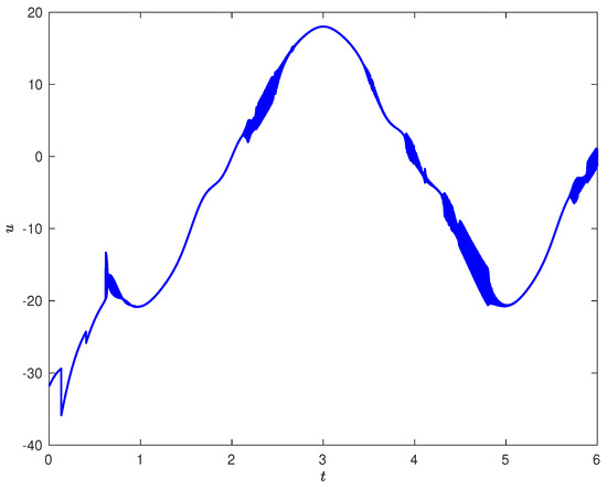
Figure 1.
The Control input u.
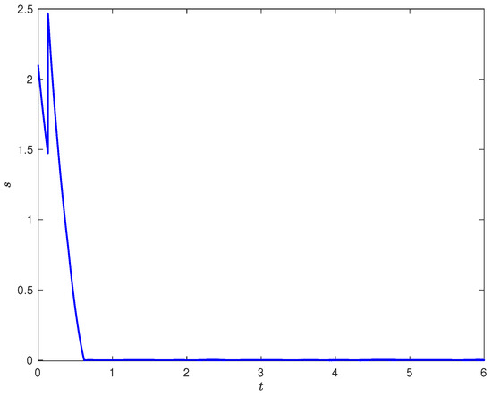
Figure 2.
The Sliding surface s.
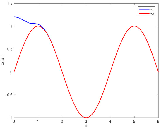
Figure 3.
The Tracking performance and .
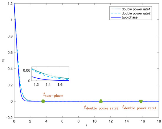
Figure 4.
The Comparison of tracking error .
Part ii. The comparison with the existing results
The analysis of the settling time for the sliding mode control scheme is the main characteristic for scholars. In this part, we are going to consider the difference between the existing results and those obtained from the analysis of the settling time. The sliding mode with double power rate is chosen as the comparator, where the results in [25,33] are both considered, described, respectively, as
Applying these two sliding mode surfaces to the SIP problems, we design the non-singular TSM controllers with these two double power rate sliding mode surfaces as
The two-phase one is referred to in the design in Part i.
According to the analysis in [25,33], the bound of settling time of the two sliding mode surfaces with double power rate are further derived as
The comparison result is depicted in Figure 4, which shows that the convergence of system states using the two-phase TSM controller has a few more advantages than the other two control schemes. More importantly, the bound of the settling time given by (19), (34) and (35) also indicates, respectively, where the two-phase sliding mode surface with finite-duration stability is plainly less conservative than the other two sliding mode surfaces, since the two-phase sliding mode surface is selected.
Part iii. The application on the industrial manipulators
The dynamics of the n-link manipulator is , where are the vectors of angular position, velocity and acceleration, respectively, and . The simulation example of the two-link rigid industrial manipulator is referred to in [18], written as
where , , , , , .
The parameters are chosen as . The initial state is given as , and the nominal values are selected as . The reference trajectory is given as .
The two-phase sliding mode surface is designed as
where . Then, the NTSMC is given as
where the parameters of the controller are chosen as , , , , , , . The simulation results are depicted in Figure 5 and Figure 6. Figure 5 shows the convergence process of the sliding mode surface, indicating the effectiveness of the presented control scheme. The tracking error is characterized in Figure 6, where satisfying performance is achieved.
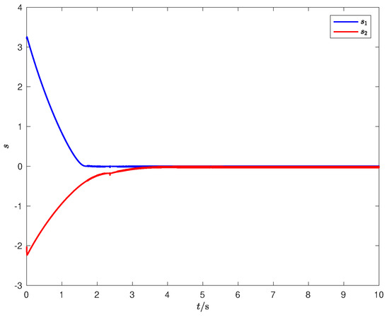
Figure 5.
The sliding mode surface s of the manipulators.
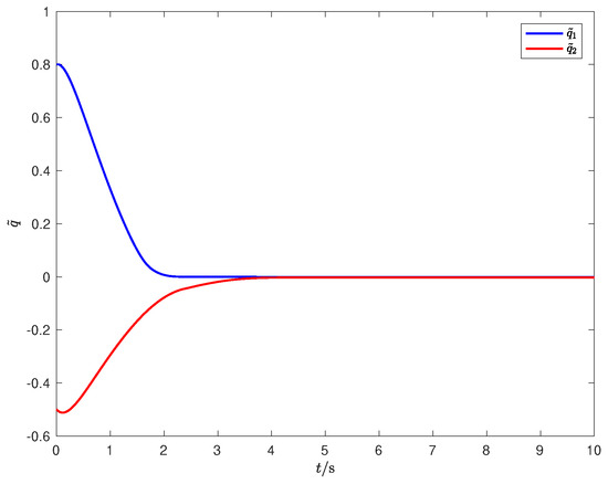
Figure 6.
The tracking error of the manipulators.
6. Conclusions
This paper has studied a fast two-phase non-singular TSM control problem for a class of nonlinear systems with external disturbances. The fast finite-duration convergence can be achieved and the closed-loop settling time is obtained, and the singularity phenomenon is overcome for the adoption of the saturation function by employing the proposed control scheme. The application of the single inverted pendulum and the industrial manipulator is conducted and the simulation results suggest the effectiveness and superiority of the proposed control scheme.
Author Contributions
Conceptualization, H.L.; methodology, H.L.; software, H.L.; validation, H.L. and C.T.; formal analysis, H.L.; investigation, H.L.; resources, H.L.; data curation, H.L.; writing—original draft preparation, H.L.; writing—review and editing, H.L.; visualization, H.L.; supervision, H.L.; project administration, H.L.; funding acquisition, H.L. All authors have read and agreed to the published version of the manuscript.
Funding
This work was supported by the Fundamental Research Funds of Zhejiang Sci-Tech University (20022305-Y).
Data Availability Statement
The data presented in this study are available on request from the corresponding author. The data are not publicly available due to the in-depth research in the future.
Conflicts of Interest
The authors declare no conflict of interest. The funders had no role in the design of the study; in the collection, analyses, or interpretation of data; in the writing of the manuscript; or in the decision to publish the results.
References
- Utkin, V.I. Sliding Modes in Control and Optimization; Springer: Berlin/Heidelberg, Germany, 1992. [Google Scholar]
- Cui, R.; Chen, L.; Yang, C.; Chen, M. Extended state observer-based integral sliding mode control for an underwater robot with unknown disturbances and uncertain nonlinearities. IEEE Trans. Industrial Elect. 2017, 64, 6785–6795. [Google Scholar] [CrossRef]
- Shao, K.; Zheng, J.; Huang, K.; Wang, H.; Man, Z.; Fu, M. Finite-time control of a linear motor positioner using adaptive recursive terminal sliding mode. IEEE Trans. Industrial Elect. 2019, 67, 6659–6668. [Google Scholar] [CrossRef]
- Wang, Z.; Li, S.; Li, Q. Continuous nonsingular terminal sliding mode control of DC–DC boost converters subject to time-varying disturbances. IEEE Trans. Circuits Syst.-II Expre. Brie. 2020, 67, 2552–2556. [Google Scholar] [CrossRef]
- Bartolini, G.; Ferrara, A.; Usai, E. Chattering avoidance by second-order sliding mode control. IEEE Trans. Autom. Contr. 1998, 43, 241–246. [Google Scholar] [CrossRef]
- Dehkordi, N.M.; Sadati, N.; Hamzeh, M. A robust backstepping high-order sliding mode control strategy for grid-connected DG units with harmonic/interharmonic current compensation capability. IEEE Trans. Susta. Ener. 2017, 8, 561–572. [Google Scholar] [CrossRef]
- He, X.; Li, X.; Song, S. Nonsingular terminal sliding-mode control of second-order systems subject to hybrid disturbances. IEEE Trans. Circuits Syst.-II: Expre. Brie. 2022, 69, 5019–5023. [Google Scholar] [CrossRef]
- Kamal, S.; Moreno, J.A.; Chalanga, A.; Bandyopadhyay, B.; Fridman, L.M. Continuous terminal sliding-mode controller. Automatica 2016, 69, 308–314. [Google Scholar] [CrossRef]
- Polyakov, A.; Poznyak, A. Reaching time estimation for super-twisting second-order sliding-mode controller via Lyapunov function designing. IEEE Trans. Autom. Contr. 2009, 54, 1951–1955. [Google Scholar] [CrossRef]
- Moreno, J.A.; Osorio, M. Strict Lyapunov functions for the super-twisting algorithm. IEEE Trans. Autom. Contr. 2012, 57, 1035–1040. [Google Scholar] [CrossRef]
- Utkin, V.I.; Poznyak, A.S. Adaptive sliding mode control with application to super-twist algorithm: Equivalent control method. Automatica 2013, 49, 39–47. [Google Scholar] [CrossRef]
- Yang, J.; Li, S.; Yu, X. Sliding-mode control for systems with mismatched uncertainties via a disturbance observer. IEEE Trans. Indus. Elect. 2013, 60, 160–169. [Google Scholar] [CrossRef]
- Sun, R.; Zhou, Z.; Zhu, X. Finite-time terminal sliding mode attitude control for tailless full-wing configuration UAVs based on extended state observers and auxiliary compensators. ISA Trans. 2023; early access. [Google Scholar] [CrossRef]
- Zak, M. Terminal actuators in neural networks. Neural Netwo. 1989, 2, 259–274. [Google Scholar] [CrossRef]
- Man, Z.; Paplinski, A.P.; Wu, H.R. A robust MIMO terminal sliding mode control scheme for rigid robotic manipulators. IEEE Trans. Autom. Contr. 1994, 39, 2464–2469. [Google Scholar]
- Chen, G.; Song, Y.; Guan, Y. Terminal sliding mode-based con- sensus tracking control for networked uncertain mechanical systems on digraphs. IEEE Trans. Neur. Netwo. Learn. Syst. 2018, 29, 749–756. [Google Scholar] [CrossRef]
- Jin, M.; Lee, J.; Ahn, K.K. Continuous nonsingular terminal sliding-mode control of shape memory alloy actuators using time delay estimation. IEEE/ASME Trans. Mecha. 2015, 20, 899–909. [Google Scholar] [CrossRef]
- Feng, Y.; Yu, X.; Man, Z. Non-singular adaptive terminal sliding mode control of rigid manipulators. Automatica 2002, 38, 2159–2167. [Google Scholar] [CrossRef]
- Yu, S.; Yu, X.; Shirinzadeh, B.; Man, Z. Continuous finite-time control for robotic manipulators with terminal sliding mode. Automatica 2005, 41, 1957–1964. [Google Scholar] [CrossRef]
- Yang, L.; Yang, J. Nonsingular fast terminal sliding-mode control for nonlinear dynamical systems. Int. Jour. Robu. Nonli. Contr. 2011, 21, 1865–1879. [Google Scholar] [CrossRef]
- Xu, S.; Chen, C.; Wu, Z. Study of nonsingular fast terminal sliding-mode fault-tolerant control. IEEE Trans. Indus. Elect. 2015, 62, 3906–3913. [Google Scholar] [CrossRef]
- Sun, Y.; Gao, Y.; Zhao, Y.; Liu, Z.; Wang, J.; Kuang, J.; Yan, F.; Liu, J. Neural network-based tracking control of uncertain robotic systems: Predefined-time nonsingular terminal sliding-mode approach. IEEE Trans. Ind. Electron. 2022, 69, 10510–10520. [Google Scholar] [CrossRef]
- Lian, S.; Meng, W.; Shao, K.; Zheng, J.; Zhu, S.; Li, H. Full attitude control of a quadrotor using fast nonsingular terminal sliding mode with angular velocity planning. IEEE Trans. Indus. Elect. 2023, 70, 3975–3984. [Google Scholar] [CrossRef]
- Feng, Y.; Yu, X.; Han, F. On nonsingular terminal sliding-mode control of nonlinear systems. Automatica 2013, 49, 1715–1722. [Google Scholar] [CrossRef]
- Zuo, Z. Non-singular fixed-time terminal sliding mode control of non-linear systems. IET Contr. Theor. Appl. 2015, 9, 545–552. [Google Scholar] [CrossRef]
- Dong, H.; Yang, X.; Kuang, Z.; Liu, M. On practical terminal sliding-mode control for systems with or without mismatched uncertainty. J. Frankl. Inst. 2022, 359, 8084–8106. [Google Scholar] [CrossRef]
- Bassetto, M.; Niccolai, L.; Boni, L.; Mengali, G.; Quarta, A.A.; Circi, C.; Pizzurro, S.; Pizzarelli, M.; Pellegrini, R.C.; Cavallini, E. Sliding mode control for attitude maneuvers of Helianthus solar sail. Acta Astronaut. 2022, 198, 100–110. [Google Scholar] [CrossRef]
- Nguyen, N.; Oh, H.; Moon, J. Continuous nonsingular terminal sliding-mode control with integral-type sliding surface for disturbed systems: Application to attitude control for quadrotor UAVs under external disturbances. IEEE Trans. Aeros. Elect. Syst. 2022, 58, 5635–5660. [Google Scholar] [CrossRef]
- Zhao, K.; Liu, W.; Zhou, R.; Dai, W.; Wu, S.; Qiu, P.; Yin, Y.; Jia, N.; Yi, J.; Huang, G.; et al. Model-free fast integral terminal sliding-mode control method based on improved fast terminal sliding-mode observer for PMSM with unknown disturbances. ISA Trans. 2023; early access. [Google Scholar] [CrossRef]
- Asadi, D.; Bagherzadeh, S. Nonlinear adaptive sliding mode tracking control of an airplane with wing damage. Proc. Inst. Mech. Eng. Part J. Aerosp. Eng. 2017, 232, 1405–1420. [Google Scholar] [CrossRef]
- Zhu, D.; Huang, P.; Du, B.; Zhu, P. Adaptive nonsingular terminal sliding mode control of robot manipulator based on contour error compensation. Sci. Rep. 2023, 13, 330. [Google Scholar]
- Polyakov, A. Nonlinear feedback design for fixed-time stabilization of linear control systems. IEEE Trans. Autom Contr. 2012, 57, 2106–2110. [Google Scholar] [CrossRef]
- Ni, J.; Liu, C.; Li, S. Fast fixed-time nonsingular terminal sliding mode control and its application to chaos suppression in power system. IEEE Trans. Circu. Sys. II Exp. Bri. 2017, 64, 151–155. [Google Scholar] [CrossRef]
- Ferrara, A.; Incremona, G.P. Predefined-time output stabilization with second order sliding mode generation. IEEE Trans. Autom. Contr. 2021, 66, 1445–1451. [Google Scholar] [CrossRef]
- Moulay, E.; Léchappé, V.; Bernuau, E.; Plestan, F. Robust fixed-time stability: Application to sliding-mode control. IEEE Trans. Autom. Contr. 2022, 67, 1061–1066. [Google Scholar] [CrossRef]
- Sun, M. Two-phase attractors for finite-duration consensus of multiagent systems. IEEE Trans. Syste. Man Cyber. Syst. 2018, 50, 1757–1765. [Google Scholar] [CrossRef]
Disclaimer/Publisher’s Note: The statements, opinions and data contained in all publications are solely those of the individual author(s) and contributor(s) and not of MDPI and/or the editor(s). MDPI and/or the editor(s) disclaim responsibility for any injury to people or property resulting from any ideas, methods, instructions or products referred to in the content. |
© 2023 by the authors. Licensee MDPI, Basel, Switzerland. This article is an open access article distributed under the terms and conditions of the Creative Commons Attribution (CC BY) license (https://creativecommons.org/licenses/by/4.0/).