Abstract
Enhanced hard magnetic properties were achieved in M-type hexaferrite by optimizing the substitution levels of Mn, Al, and Si for Fe, and Ca for Sr within SrFe12O19. The addition of Al–Si–Mn effectively controlled crystallite growth, resulting in an increased coercivity (HC), while causing a decrease in the remanent magnetization (4πMr). A higher Ca content exhibited a trend of increasing the sintered density but decreasing the 4πMr and HC. The optimized composition, considering both the 4πMr and HC, was determined to be Sr0.8Ca0.2Fe10.2Mn0.1Al0.2Si0.1O19−d, with a sintered density of 4.84 g/cm3, 4πMr = 2.22 kG, and HC = 5.10 kOe. This result demonstrates the achievement of isotropic magnets with controlled crystal growth and densification without additional sintering additives. This development is promising, as this enhancement could be achieved without the use of cobalt, an expensive but essential ingredient in high-performance permanent magnets.
1. Introduction
M-type hexaferrites (M-hexaferrites) with the chemical formula (Ba,Sr)Fe12O19 are utilized as permanent magnet materials due to their strong c axis magnetocrystalline anisotropy (MCA) and sufficient saturation magnetization (MS) [1,2]. Ferrite magnets are widely employed in various applications such as automotive, household appliances, and industrial equipment, including motors, compressors, transformers, and speakers, owing to their ease of fabrication under atmospheric conditions, excellent chemical stability, and cost-effectiveness. Ferrite magnets account for approximately 85% of the total mass of permanent magnets used worldwide [3], underscoring the economic and industrial significance of developing the advanced characteristics of M-hexaferrites.
Research efforts have been extensively conducted to enhance intrinsic magnetic properties, such as MS and MCA, by substituting various ions in SrFe12O19 or BaFe12O19 [2,4,5,6,7,8,9,10,11,12,13,14,15,16,17,18,19,20,21,22,23,24,25]. In some cases, the selective substitution of non-magnetic elements like Zn for Fe’s down-spin sites has led to an improved MS in M-hexaferrites [4,5,6,7,8]. However, this has also resulted in a decrease in the MCA, leading to a reduction coercivity (HC), and these materials have not been widely adopted as high-performance permanent magnets. On the other hand, M-hexaferrites with the simultaneous substitution of La-Co have been developed and used as high-performance permanent magnets [9,10,11,12,13,14]. In these cases, the substitution does not decrease the MS while significantly increasing the MCA. An intriguing observation here is that when La3+-Co2+ ions are simultaneously substituted for Sr2+-Fe3+ ions in SrFe12O19, the MCA of M-hexaferrite significantly increases without a significant reduction in the MS. However, when La or Co is substituted individually, such a remarkable improvement in characteristics cannot be achieved. Furthermore, when Co2+-Ti4+ ions are substituted simultaneously for Fe3+ ions, there is an opposite trend, where MCA decreases as the substitution level increases [26], in contrast to the substitution with La3+-Co2+. Therefore, research has extensively focused on the combinations of various substituting elements to enhance magnetic characteristics. Despite numerous studies, manufacturing high-performance ferrite magnets has remained challenging, and more effective results than the substitution of La3+-Co2+ have not been achieved. Since the cost of Co is significantly higher than that of other elements, developing cation substitution compositions that reduce or completely eliminate the need for Co is of paramount importance.
Recent advances in the field of hard magnetic materials have shown significant improvements in hexaferrite nanomagnets prepared using sol–gel-based methods [12,27,28]. These studies have demonstrated the attainment of a substantial HC exceeding 6 kOe, primarily due to the nanocrystallization of hexaferrite grains. It is well-established that the coercivity of a single grain (hC) increases as its size decreases, reaching the upper limit defined by the critical grain diameter for a single domain (dcri). This phenomenon exhibits a reciprocal dependence on the grain size (d), expressed by the following equation [29]:
hC = dcri/d1.08
However, when considering the practical application of sintered magnets, a method capable of mass production through solid-state reaction processes becomes imperative, as opposed to chemical synthesis methods like those of sol–gels.
Even when the magnetic properties of M-hexaferrite, such as the MS and MCA, are improved through cation substitution during the calcination powder stage, these properties often deteriorate again due to the influence of sintering additives during the sintering process. Therefore, it is crucial to develop cation substitution compositions while considering the impact of sintering additives. Commonly used sintering additives, such as SiO2, play a significant role in controlling crystalline grain growth. However, during high-temperature sintering, Si can infiltrate the M-hexaferrite lattice, leading to a tendency to reduce magnetic properties like MS [13,22]. Additionally, sintering additives like CaO and CaCO3 promote grain growth and densification during sintering and can also affect the magnetic properties of M-hexaferrites when substituting for Sr or Fe sites [7,16,21,22,23].
In this study, our objective was to develop sintered magnets with improved magnetic properties, all while avoiding the use of sintering additives. To achieve this, we designed compositions such as Sr0.8Ca0.2Fe12−3xMnxAlxSixO19−d, which incorporate essential elements like Si and Ca, known for their role in controlling grain growth and densification during sintering. Our choice of Mn as a dopant is due to its close similarity in size to Fe, and previous research has demonstrated that even small amounts of Mn substitution can enhance magnetic properties, such as the MS [5,6,7,21,22,23]. We systematically adjusted the doping levels of Mn, Al, and Ca during the optimization process. In this composition formula, we represent the oxygen content as O19−d, maintaining the charge balance between cations and oxygen ions. The substitution of Al and Si serves a function akin to sintering additives, effectively suppressing grain growth. In our previous research, we effectively controlled grain growth using only Si as an element [22,23]. However, in this study, we can expect to achieve an even better HC with the combined action of Al and Si. When combined with the magnetic element Mn, we anticipated improvements in the magnetic properties at the optimal composition. Our goal was to identify the ideal substitution levels to enhance the magnetic characteristics. We conducted a comprehensive analysis of the crystalline phase, microstructure, and magnetic properties resulting from these substitutions, ultimately yielding a composition with cation substitutions well-suited for use as a ferrite permanent magnet.
2. Materials and Methods
To synthesize M-type Sr-hexaferrites with the cationic composition ratios of Sr0.8Ca0.2Fe11−3xMnxAlxSix, Sr0.8Ca0.2Fe10.7−x−yMn0.1+xAl0.1+ySi0.1, Sr0.7+zCa0.3−zFe10.2Mn0.1Al0.2Si0.1, and Sr0.7+zCa0.3−zFe9.7Mn0.1Al0.2Si0.1 (0 ≤ x, y, z ≤ 0.2), a solid-state reaction method was employed. Setting the atomic ratio of [Sr-site]/[Fe-site] in the chemical formula to 11 instead of 12 was based on the experimental results from previous research [5,6], aiming to suppress the formation of the secondary phase of Fe2O3. Powders of Fe2O3 (99%, industrial use, Pohang, South Korea), SrCO3 (99.9%, Kojundo Chemical, Sakado, Japan), CaCO3 (98%, Showa chemical, Minato, Japan), Co3O4 (98%, Top new energy tech. Co., Xiamen, China), MnCO3 (99.9%, Kojundo Chemical, Sakado, Japan), La2O3 (Sigma-Aldrich, 99.9%, St. Louis, MO, USA), and SiO2 (99.5%, JK Silica Co., Shaxian, China) were weighed according to the cationic composition ratios. The weighed powders were mixed with distilled water in sample containers (Nalgene) and subjected to wet ball milling at 120 rpm for 20 h using zirconia balls. The fully dried powders were placed in alumina crucibles and calcined at 1100 °C for 4 h in an atmospheric electric furnace. After calcination, the powders were crushed, followed by a second 24 h wet milling. The milled powders were then dried and sieved through a 200 mesh sieve. A total of 5 g of the sieved powder was placed into a disk-shaped mold (20 mm diameter) and molded under a pressure of 0.3 tons. The molded samples were then sintered in an electric furnace under atmospheric conditions at 1210 °C for 2 h. During the ramp-up and ramp-down phases of the heating process, the furnace temperature was controlled at a rate of 5 °C/min, while natural cooling (furnace cooling) was employed during the cooling phase.
The density of the samples was calculated from the external dimensions and mass of the sintered disk-shaped samples. For phase analysis, the sintered samples were powdered, and X-ray diffraction (XRD) analysis was performed using an X-ray diffractometer (D8 Advance, Bruker, Karlsruhe, Germany) with Cu Kα radiation (λ = 0.154056 nm). For microstructure observation, the fractured surface of the sintered samples were examined using a field emission scanning electron microscope (FE-SEM, JSM-7610F, JEOL, Tokyo, Japan). Magnetic properties were characterized by measuring the M-H curves of the sintered samples using a B-H loop tracer (BH-5501, Denshijiki Industry, Tokyo, Japan). The demagnetization curves in the second quadrant, measured by applying a maximum magnetic field of 25 kOe and then gradually decreasing the magnetic field, are presented.
3. Results and Discussion
3.1. Crystalline Structure and Microstructure Analysis
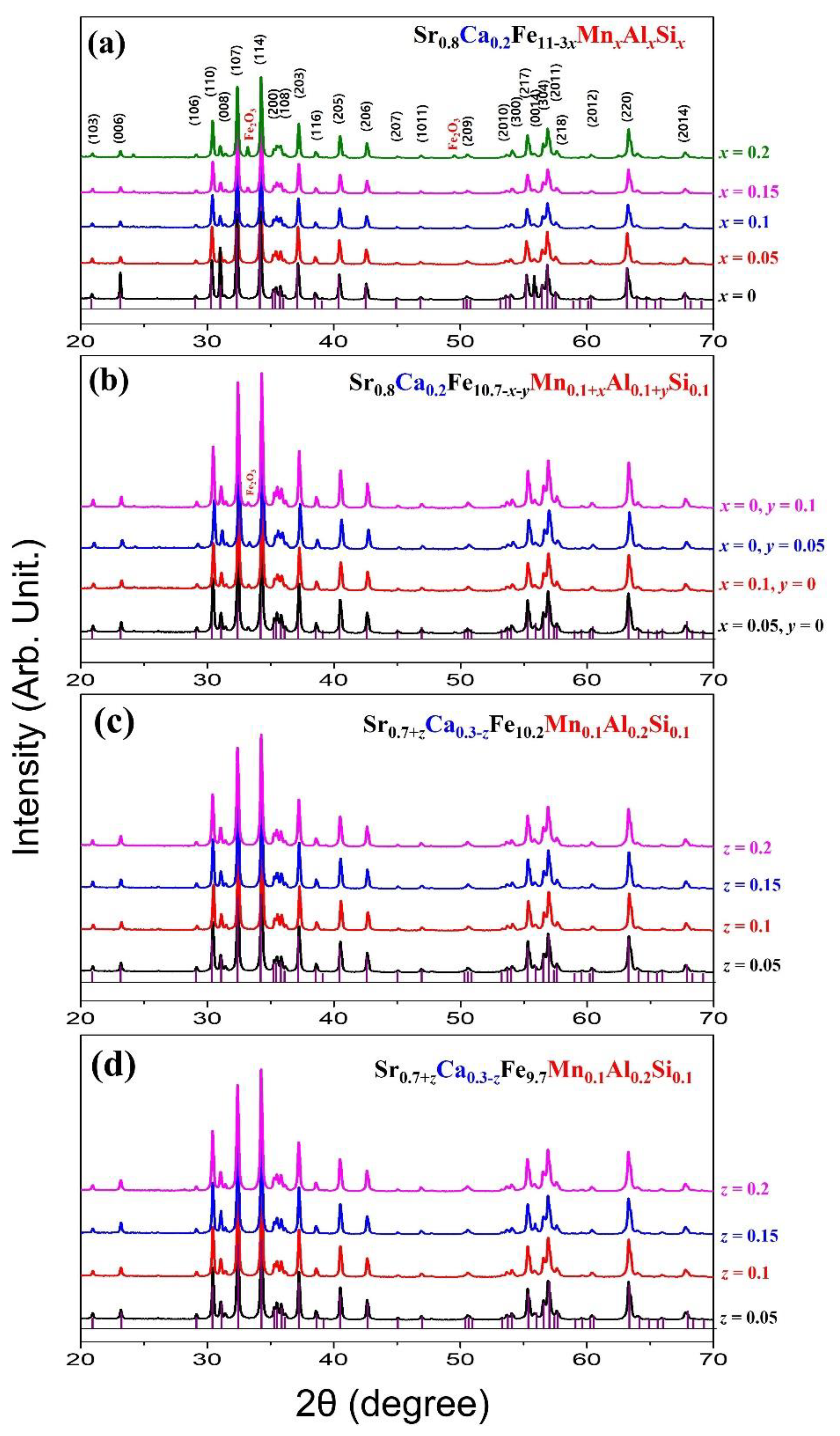
Figure 1a–d present the XRD patterns of the M-hexaferrite samples synthesized in this study in four series, based on different cationic compositions. All the samples were obtained through calcination at 1100 °C in an air atmosphere and sintering at 1210 °C. The XRD patterns of the M-hexaferrite phase were indexed based on the International Center for Diffraction Data (ICDD) with the pdf search number SrM: 00-033-1340. For some samples, the peak positions of the secondary phase Fe2O3 (ICDD, 33-0664) that occurred in certain samples are also indicated. In Figure 1a, the formation of the M-hexaferrite phase in Sr0.8Ca0.2Fe11−3xMnxAlxSixO19−d, where 20% of Sr in the basic composition of M-hexaferrite SrFe12O19 is substituted with Ca, and Fe is simultaneously substituted with Mn, Al, and Si, is shown. For x = 0 and 0.05, a pure M-hexaferrite phase is formed, whereas for x = 0.1, a small Fe2O3 peak is observed, and as x increases to 0.15 and 0.2, the Fe2O3 peak becomes significantly more pronounced. For the x = 0 composition, it can be observed that the 00l peaks, such as 006, 008, and 0014, are significantly higher compared to the other compositions. This result can be explained as follows: in samples with large grain growth, wide plate-like hexaferrite grains are abundant even in the powdered state. During the packing of the powder into the sample holder for the XRD measurements, the c-axes of each grain align perpendicular to the sample holder’s surface. This phenomenon has been reported in previous studies on hexaferrites [7,16,23]. Figure 1b shows the XRD patterns of Sr0.8Ca0.2Fe10.7−3xMn0.1+xAl0.1+ySi0.1O19−d (0 ≤ x, y ≤ 0.1), in which either of the Mn and Al substitution levels are increased from one of the first series samples, Sr0.8Ca0.2Fe10.7Mn0.1Al0.1Si0.1O19−d (x = 0). All four samples show the presence of a secondary phase Fe2O3 in small amounts. Figure 1c,d display the XRD patterns of two series samples, Sr0.7+zCa0.3−zFe10.2Mn0.1Al0.2Si0.11O19−d and Sr0.7+zCa0.3−zFe9.7Mn0.1Al0.2Si0.11O19−d (z = 0.05, 0.1, 0.15, 0.2). In these samples, the ratio of Sr:Ca is varied and the Fe content in the formula is reduced from 10.6 to 10.2 and 9.7, respectively. All eight samples in Figure 1c,d are single-phase M-hexaferrites. The phases of each composition confirmed from the XRD analysis are summarized in Table 1.
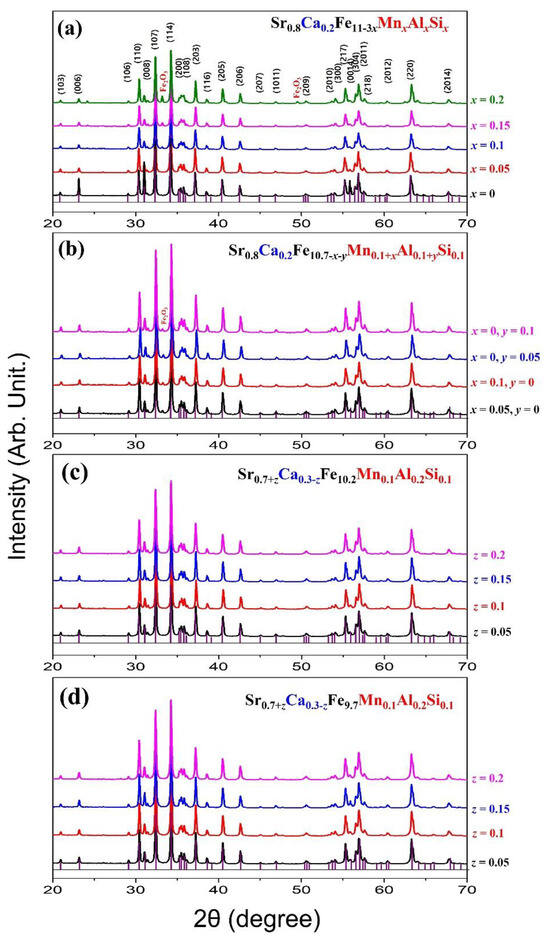
Figure 1.
XRD patterns of M-hexaferrites, (a) Sr0.8Ca0.2Fe11−3xMnxAlxSixO19−d, (b) Sr0.8Ca0.2Fe10.7−3xMn0.1+xAl0.1+ySi0.1O19−d, (c) Sr0.7+zCa0.3−zFe10.2Mn0.1Al0.2Si0.1O19−d, (d) Sr0.7+zCa0.3−zFe9.7Mn0.1Al0.2Si0.1O19−d sintered at 1210 °C.

Table 1.
Sample composition with substitution content (x, y, z), sintering temperature (TS), cell volume (Vol), sintered sample density (ρ), saturation magnetization (4πMS), and coercivity (HC) of the sintered hexaferrite samples.
Additionally, the lattice constants a, c, and the unit cell volume (V) were calculated from the XRD peaks and are presented in Table 1. The a and c are calculated from the values of dhkl corresponding to the (107) and (114) peaks, according to the following equation:
where dhkl is the interplanar spacing, and h, k, and l are the Miller indices. As the substitution level x increases, the unit cell volume generally decreases due to the smaller average ionic radii of Mn3+, Al2+, and Si4+ compared to Fe3+. Furthermore, since Sr2+ has a larger ionic radius than Ca2+, it could be expected that the unit cell volume would increase with increasing z. However, this trend is not observed in this experiment.
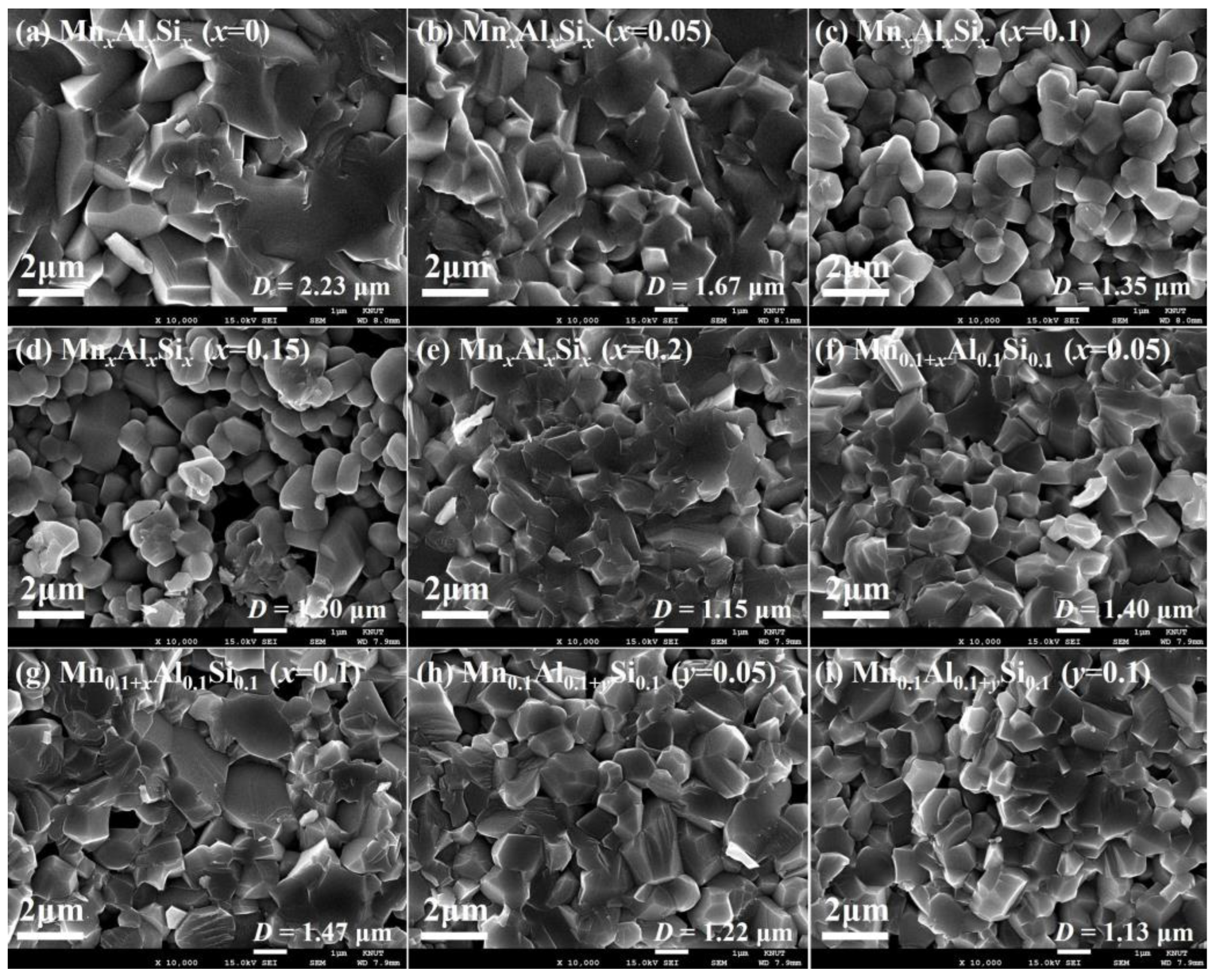
Figure 2a–e illustrate the changes in the microstructure with increasing x in sintered Sr0.8Ca0.2Fe11−3xMnxAlxSixO19−d samples. The average grain size (D) was determined using a random intercept method applied to SEM micrographs and is presented in the lower right corner of each figure. Notably, when Mn–Al–Si substitutions are absent (x = 0), the average grain size is the largest, at D = 2.23 μm. With increasing x, there is a consistent trend of decreasing D. Given that the substitution of Mn–Al–Si does not significantly affect the MCA of M-hexaferrite, it can be explained that HC is primarily dependent on D. As discussed earlier in Equation (1), the coercivity of an individual grain (hC) exhibits an inverse relationship with its size (d), which can aptly account for these variations. The abnormally high intensity of the (00l) plane peaks in the XRD pattern of the x = 0 sample (Figure 1a) is attributed to the growth of hexagonal plate-like crystals, which can be observed in Figure 2a. In Figure 2c–e, for samples with x ≥ 0.1, a uniform grain size distribution is evident, with D ranging between 1.15 and 1.33 μm. In Figure 2f,g, when the Mn substitution level is increased to 0.15 and 0.2, a slight increase in D is observed. However, in Figure 2h,i, as the Al substitution level increases to 0.15 and 0.2, there is a slight tendency for D to decrease. The apparent density of the sintered samples for each composition is presented in Table 1.

Figure 2.
SEM micrographs of sintered (a–e) Sr0.8Ca0.2Fe11−3xMnxAlxSixO19−d with x = 0, 0.05, 0.1, 0.15, 0.2, and (f–i) Sr0.8Ca0.2Fe10.7−3xMn0.1+xAl0.1+ySi0.1O19−d with x, y = 0.05, 0.1, sintered at 1210 °C.
3.2. Magnetic Property Analysis
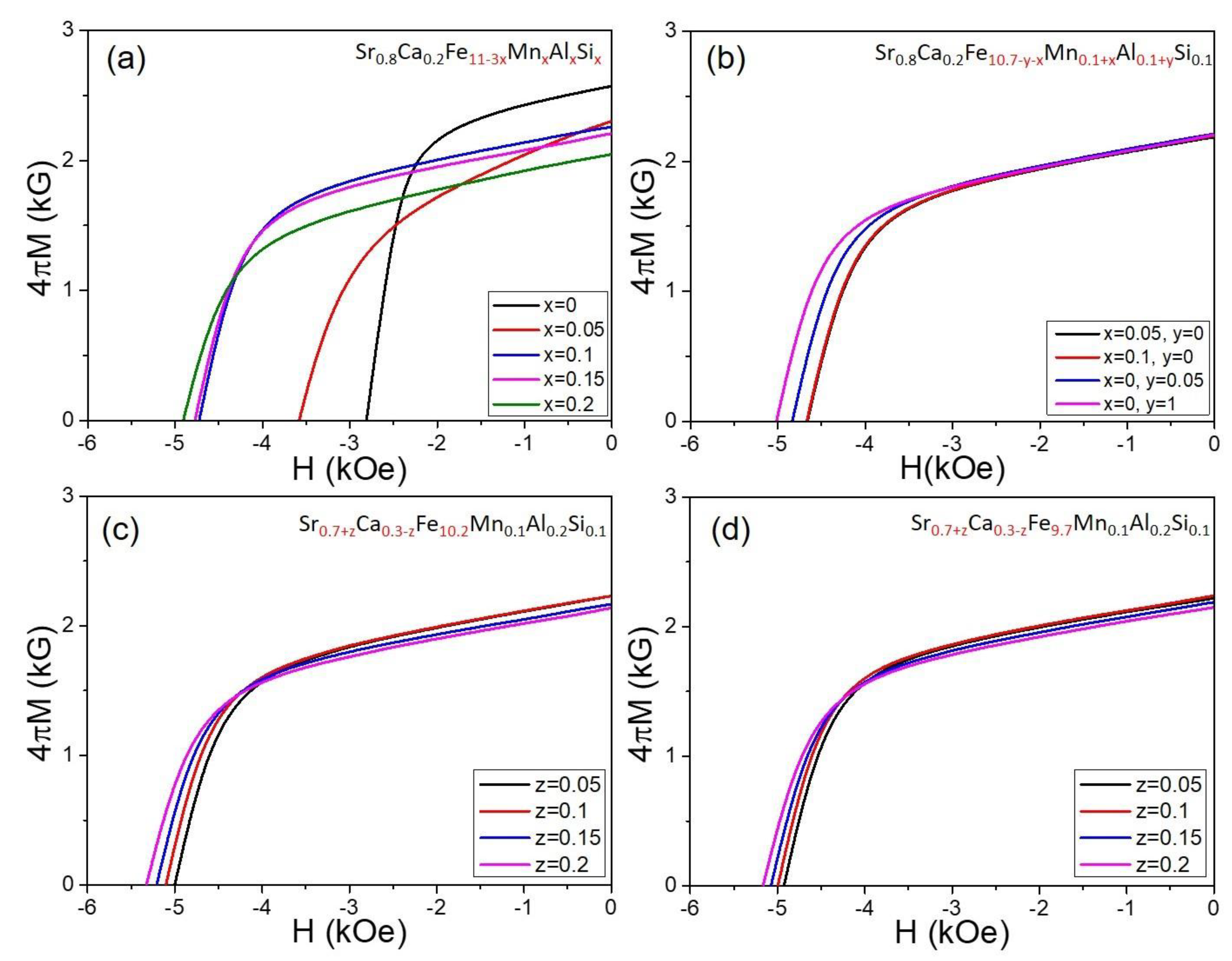
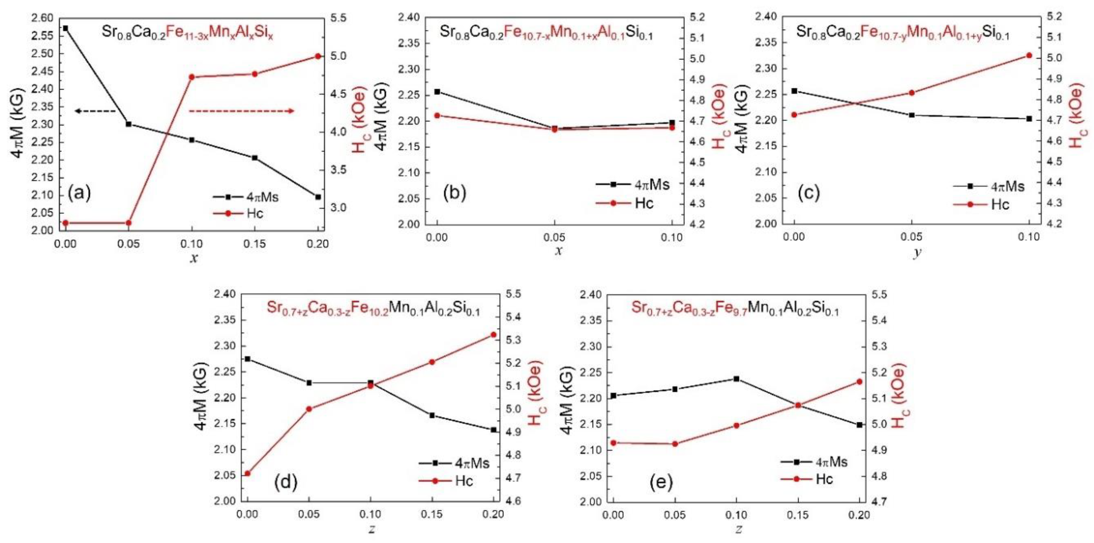
Figure 3a–d display the demagnetization curves (4πM-H) of samples for each composition in the four series. Additionally, to facilitate an easy assessment of the changes in the residual magnetization (4πMr) and coercivity (HC) of the samples obtained here, we have plotted them as a function of the substitution level x, y, and z in Figure 4a–e. The precise data values are provided in Table 1. In Figure 3a, it can be observed that the demagnetization curves vary significantly with respect to the Mn–Al–Si substitution level, x. As x increases, 4πMr decreases, while HC shows an increasing trend. When there is no secondary phase, 4πMr can be expressed in terms of the MS, sintered density (ρ), and squareness (S), as follows [7,23]:
here, 4πMr is the remanent magnetization in Gauss units, MS is the saturation magnetization in emu/g unit, ρ is the sintered density in g/cm3, and S represents the squareness, which is a measure of the degree of alignment along the c axis in the crystallites. It can be expressed as the ratio of the remanent magnetization to saturation magnetization (S = Mr/MS). The saturation magnetization in Gauss units (4πMS) can be estimated as twice the value of 4πMr in the case of an isotropic magnet, where the crystalline grains are randomly oriented. Since the MS of Sr M-hexaferrite in the units of emu/g is known to be 72 emu/g [2,3], the theoretical 4πMS can be approximately 4600 G. In this case, for a perfectly isotropic magnet with a theoretical density of 5.1 g/cm3, the 4πMr would be around 2300 G.
4πMr = MS·ρ·S
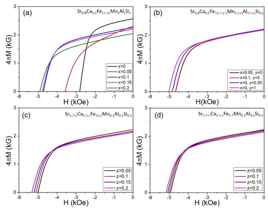
Figure 3.
Demagnetization curves of hexaferrite samples, (a) Sr0.8Ca0.2Fe11−3xMnxAlxSixO19−d, (b) Sr0.8Ca0.2Fe10.7−3xMn0.1+xAl0.1+ySi0.1O19−d, (c) Sr0.7+zCa0.3−zFe10.2Mn0.1Al0.2Si0.1O19−d, and (d) Sr0.7+zCa0.3−zFe9.7Mn0.1Al0.2Si0.1O19−d (0 ≤ x, y, z ≤ 0.2).
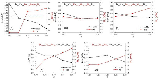
Figure 4.
(a–e) Dependence of 4πMr and HC on substitution compositions (x, y, z) of the M-hexaferrites.
In Figure 3a, the x = 0 sample exhibits a significantly higher 4πMr of 2570 G than the expected 4πMr for a perfectly isotropic magnet. This can be attributed to some degree to the c axis alignment in the crystallites. Based on the size and shape of the crystalline grains observed in the SEM images in Figure 2a, it can be inferred that the x = 0 sample maintains hexagonal plate-like crystallites even after secondary ball milling and exhibits some c axis alignment after the molding process into disk shapes. The x = 0.05 sample shown in Figure 2b is also expected to show a weaker degree of c axis alignment for the same reasons. For samples with x ≥ 0.1, as shown in Figure 3a, considering the size and shape of the crystallites from Figure 2c–e, they are expected to be nearly perfectly isotropic. Therefore, the 4πMS for these samples can be roughly estimated as twice the value of the 4πMr. In these samples (x ≥ 0.1), the crystalline grain size and distribution are uniform. In Figure 4a, it is noticeable that the HC sharply increases at x = 0.1. Among the samples in the series presented in Figure 3a for Sr0.8Ca0.2Fe11−3xMnxAlxSixO19−d, when considering both the 4πMr and HC values, it is concluded that the composition at x = 0.1, Sr0.8Ca0.2Fe10.7Mn0.1Al0.1Si0.1O19−d, exhibits the most optimized results for permanent magnet applications. Additionally, there is still room for improvement in 4πMr through improving the sintering density and removing the second phase Fe2O3.
Figure 3b shows the demagnetization curves of Sr0.8Ca0.2Fe10.7−x−yMn0.1+xAl0.1+ySi0.1O19−d (0 ≤ x, y ≤ 0.1), in which either of the Mn and Al substitution levels are increased from the first optimized composition in Figure 3a, Sr0.8Ca0.2Fe10.7Mn0.1Al0.1Si0.1O19−d (x = 0). Among the four demagnetization curves, it can be observed that there is a significant improvement in HC when adding Al content with y = 0.1, while the 4πMS values remain relatively consistent. In Figure 4b,c, one can easily compare the relative magnitude of the 4πMr and HC values for these samples. Therefore, based on these results, the second optimized composition can be derived as Sr0.8Ca0.2Fe10.6Mn0.1Al0.2Si0.1O19−d.
The XRD phase analysis results presented in Figure 1 show that all four samples shown in Figure 3b contain a secondary phase of Fe2O3. Therefore, the Fe content in the chemical formula was reduced from the stoichiometric composition of 10.6 to 10.2 and 9.7, respectively, while the Sr:Ca ratio was slightly adjusted. The results for these two series of compositions, Sr0.7+zCa0.3−zFe10.2Mn0.1Al0.2Si0.1O19−d and Sr0.7+zCa0.3−zFe9.7Mn0.1Al0.2Si0.1O19−d (z = 0, 0.05, 0.1, 0.15, 0.2), are presented in Figure 3c and Figure 4d, respectively. The changes in the 4πMr and HC values with respect to z are also plotted in Figure 4d,e. In both cases, an increase in z (corresponding to a decrease in the Ca content) leads to an increase in HC, and a decrease in the 4πMS values, roughly. This is related to the tendency of the Ca content to promote grain growth. Furthermore, the composition with z = 0.1, which corresponds to Sr:Ca = 0.8:0.2, exhibited the highest sintered density. Considering both the 4πMr and HC values, the composition with the Fe content at 10.2 and z = 0.1 (i.e., Sr0.8Ca0.2Fe10.2Mn0.1Al0.2Si0.1O19−d) can be derived as the final optimized composition.
In ferrite magnets, it is well-known that there is a trade-off relationship between 4πMr and HC. To confirm this trend observed in the five series of compositions in this study, the 4πMr and HC of all the samples were plotted as points in a two-dimensional plane (x, y) and presented in Figure 5. Each series of samples is represented by shapes and colors of the same type. Furthermore, a trend line with a consistent slope from the bottom-left to the top-right are drawn from the coordinate points of each series, helping distinguish the positions of the points. A specific point that trends towards the upper-right direction indicates superior permanent magnet properties. In the first series, Sr0.8Ca0.2Fe11−3xMnxAlxSixO19−d (x = 0, 0.05, 0.1, 0.15, 0.2), it is confirmed that the composition with x = 0.1 is positioned most towards the upper-right direction. In the second series, Sr0.8Ca0.2Fe10.7−3xMn0.1+xAl0.1+ySi0.1O19−d, when additional Al substitution (y = 0.1) is applied, it is observed that this composition is located most towards the upper-right direction. Finally, in the two series where the Sr:Ca ratio is adjusted, Sr0.7+zCa0.3−zFe10.2Mn0.1Al0.2Si0.1O19−d, Sr0.7+zCa0.3−zFe9.7Mn0.1Al0.2Si0.1O19−d (z = 0, 0.05, 0.1, 0.15, 0.2), it is again confirmed that the composition with z = 0.1 is positioned most towards the upper-right direction. This analysis reaffirms the validity of the step-by-step optimization process to derive the final optimized composition for the permanent magnet properties in each series of compositions.
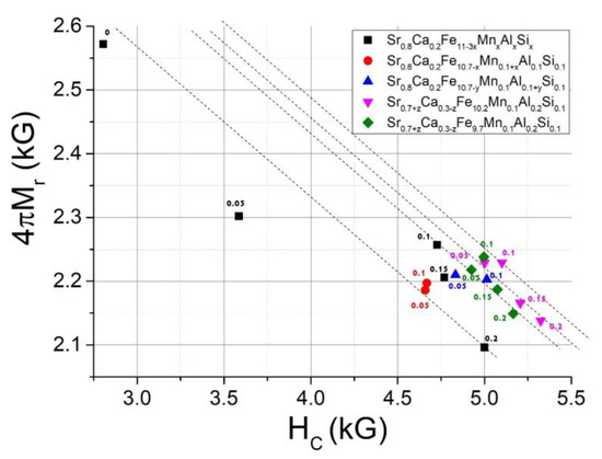
Figure 5.
Plot of 4πMr and HC of the sintered hexaferrite samples.
4. Conclusions
In this study, M-hexaferrites (SrFe12O19) with Mn–Al–Si and Ca substitutions were fabricated by a solid-state reaction, and their crystalline structure, microstructure, and magnetic properties were evaluated. The goal was to optimize the cation substitution composition for permanent magnets by considering two key magnetic properties, 4πMr and HC. It was also planned to achieve grain growth inhibition and densification through the compositional control of the initial raw materials without adding separate sintering additives. Initially, in the composition Sr0.8Ca0.2Fe11−3xMnxAlxSixO19−d, we obtained a significant improvement in the magnetic properties, with a well-controlled grain size at x = 0.1, that is, Sr0.8Ca0.2Fe10.7Mn0.1Al0.1Si0.1O19−d, resulting in an increased HC. From there, we increased the Mn and Al content step by step in the composition Sr0.8Ca0.2Fe10.7−x−yMn0.1+xAl0.1+ySi0.1O19−d, and it was observed that the composition with x = 0 and y = 0.1 exhibited the best magnetic properties (4πMr = 2.20 kG, HC = 5.01 kOe). However, it was noted that Fe2O3 existed in trace amounts as a secondary phase. In the next step, the Fe content was reduced, and the Sr to Ca ratio was adjusted in two compositions, Sr0.7+zCa0.3−zFe10.2Mn0.1Al0.2Si0.1O19−d and Sr0.7+zCa0.3−zFe9.7Mn0.1Al0.2Si0.1O19−d (z = 0.05, 0.1, 0.15, 0.2), resulting in the final optimized composition, Sr0.8Ca0.2Fe10.2Mn0.1Al0.2Si0.1O19−d. This sample exhibited a sintered density ρ = 4.84 g/cm3, 4πMr = 2.22 kG, and HC = 5.10 kOe. This result is achieved in a completely isotropic magnet with no crystal orientation. Through the implementation of high-energy ball milling to obtain finer powders, which enhances the sintering density, and the application of a magnetic field pressing to align the c axis crystal orientation, there is potential to develop an anisotropic magnet with an Mr/Ms = 0.95 and ρ = 5.0 g/cm3 [21,22,23]. Based on these assumptions, we anticipate that further process optimization will enable the same composition of anisotropic magnets to achieve 4πMr = 4.40 kG, HC = 4.8 kOe, and a maximum energy product (BHmax) of 4.65 M·G·Oe. Overall, these results are highly promising, particularly as they were achieved without the need for cobalt, a costly material typically essential for high-performance ferrite magnets.
Author Contributions
Conceptualization, Y.-M.K.; funding acquisition, Y.-M.K.; investigation, Y.-M.K.; methodology, J.-P.L. and E.-H.Y.; project administration, Y.-M.K.; software, J.-P.L. and E.-H.Y.; supervision, Y.-M.K.; writing—original draft, Y.-M.K. All authors have read and agreed to the published version of the manuscript.
Funding
This research was supported by “Regional Innovation Strategy (RIS)” through the National Research Foundation of Korea (NRF), funded by the Ministry of Education (MOE) (2021RIS-001).
Institutional Review Board Statement
Not applicable.
Informed Consent Statement
Not applicable.
Data Availability Statement
The data presented in this study are available on request from the corresponding author. The data are not publicly available due to privacy.
Acknowledgments
The authors are also grateful to Union Materials Corp. in Pohang, South Korea, for the support with the raw materials for the magnet fabrication.
Conflicts of Interest
The authors declare no conflict of interest.
References
- Went, J.; Rathenau, G.; Gorter, E.; Oosterhout, G.V. Ferroxdure, a class of new permanent magnet materials. Philips Tech. Rev. 1952, 13, 194–208. [Google Scholar]
- Pullar, R.C. Hexagonal ferrites: A review of the synthesis, properties and applications of hexaferrite ceramics. Prog. Mater. Sci. 2012, 57, 1191–1334. [Google Scholar] [CrossRef]
- Granados-Miralles, C.; Jenuš, P. On the potential of hard ferrite ceramics for permanent magnet technology—A review on sintering strategies. J. Phys. D Appl. Phys. 2021, 54, 303001. [Google Scholar] [CrossRef]
- Bai, J.; Liu, X.; Xie, T.; Wei, F.; Yang, Z. The effects of La–Zn substitution on the magnetic properties of Sr-magnetoplumbite ferrite nano-particles. Mater. Sci. Eng. B 2000, 68, 182–185. [Google Scholar] [CrossRef]
- Kang, Y.-M.; Kwon, Y.-H.; Kim, M.-H.; Lee, D.-Y. Enhancement of magnetic properties in Mn-Zn substituted M-type Sr-hexaferrites. J. Magn. Magn. Mater. 2015, 382, 10–14. [Google Scholar] [CrossRef]
- Kang, Y.-M.; Moon, K.-S. Magnetic properties of Ce-Mn substituted M-type Sr-hexaferrites. Ceram. Int. 2015, 41, 12828–12834. [Google Scholar] [CrossRef]
- Moon, K.-S.; Kang, Y.-M. Structural and magnetic properties of Ca-Mn-Zn-substituted M-type Sr-hexaferrites. J. Eur. Ceram. Soc. 2016, 36, 3383–3389. [Google Scholar] [CrossRef]
- Huang, K.; Yu, J.; Zhang, L.; Xu, J.; Yang, Z.; Liu, C.; Wang, W.; Kan, X. Structural and magnetic properties of Gd–Zn substituted M-type Ba–Sr hexaferrites by sol-gel auto-combustion method. J. Alloys Compd. 2019, 803, 971–980. [Google Scholar] [CrossRef]
- Kools, F.; Morel, A.; Grössinger, R.; Le Breton, J.M.; Tenaud, P. LaCo-substituted ferrite magnets, a new class of high-grade ceramic magnets; intrinsic and microstructural aspects. J. Magn. Magn. Mater. 2002, 242–245, 1270–1276. [Google Scholar] [CrossRef]
- Ogata, Y.; Takami, T.; Kubota, Y. Development of La-Co Substituted Ferrite Magnets. J. Jpn. Soc. Powder Powder Metall. 2003, 50, 636–641. [Google Scholar] [CrossRef]
- Kobayashi, Y.; Hosokawa, S.; Oda, E.; Toyota, S. Magnetic properties and composition of Ca-La-Co M-type ferrites. J. Jpn. Soc. Powder Powder Metall. 2008, 55, 541–546. [Google Scholar] [CrossRef]
- Lee, J.; Lee, E.J.; Hwang, T.-Y.; Kim, J.; Choa, Y.-H. Anisotropic characteristics and improved magnetic performance of Ca–La–Co-substituted strontium hexaferrite nanomagnets. Sci. Rep. 2020, 10, 15929. [Google Scholar] [CrossRef] [PubMed]
- Moon, K.-S.; Yu, P.-Y.; Kang, Y.-M. Microstructure and magnetic properties of La-Ca-Co substituted M-type Sr-hexaferrites with controlled Si diffusion. Appl. Sci. 2020, 10, 7570. [Google Scholar] [CrossRef]
- Zhou, Y.; Jiang, T.; Xu, B.; Dong, Z.; Wu, J.; Zhang, M.; Chen, Y.; Zhong, S. Clean and economical preparation of Ca-La-Co substituted permanent ferrite magnet with ultrapure magnetite concentrate. J. Alloys Compd. 2023, 956, 170334. [Google Scholar] [CrossRef]
- Yasmin, N.; Mirza, M.; Muhammad, S.; Zahid, M.; Ahmad, M.; Awan, M.S.; Muhammad, A. Influence of samarium substitution on the structural and magnetic properties of M-type hexagonal ferrites. J. Magn. Magn. Mater. 2018, 446, 276–281. [Google Scholar] [CrossRef]
- Moon, K.-S.; Lim, E.-S.; Kang, Y.-M. Effect of Ca and La substitution on the structure and magnetic properties of M-type Sr-hexaferrites. J. Alloys Compd. 2019, 771, 350–355. [Google Scholar] [CrossRef]
- Almessiere, M.A.; Slimani, Y.; Güner, S.; van Leusen, J.; Baykal, A.; Kögerler, P. Effect of Nb3+ ion substitution on the magnetic properties of SrFe12O19 hexaferrites. J. Mater. Sci. Mater. Electron. 2019, 30, 11181–11192. [Google Scholar] [CrossRef]
- Todkar, G.B.; Kunale, R.A.; Kamble, R.N.; Batoo, K.M.; Ijaz, M.F.; Imran, A.; Hadi, M.; Raslan, E.H.; Shirsath, S.E.; Kadam, R.H. Ce–Dy substituted barium hexaferrite nanoparticles with large coercivity for permanent magnet and microwave absorber application. J. Phys. D Appl. Phys. 2021, 54, 294001. [Google Scholar] [CrossRef]
- Han, G.; Sui, R.; Yu, Y.; Wang, L.; Li, M.; Li, J.; Liu, H.; Yang, W. Structure and magnetic properties of the porous Al-substituted barium hexaferrites. J. Magn. Magn. Mater. 2021, 528, 167824. [Google Scholar] [CrossRef]
- Manglam, M.K.; Shukla, A.; Mallick, J.; Yadav, M.K.; Kumari, S.; Zope, M.; Kar, M. Enhancement of coercivity of M-type barium hexaferrite by Ho doping. Mater. Today Proc. 2022, 59, 149–152. [Google Scholar] [CrossRef]
- Yu, P.-Y.; Kim, M.-H.; Kang, Y.-M. Development of a high-performance ferrite magnet fabrication process without sintering additives. Korean J. Met. Mater. 2021, 59, 551–559. [Google Scholar] [CrossRef]
- Yoo, J.-Y.; Lee, K.-H.; Kang, Y.-M.; Yoo, S.-I. Enhancement of the magnetic properties in Si4+-Li+-substituted M-type hexaferrites for permanent magnets. Appl. Sci. 2022, 12, 12295. [Google Scholar] [CrossRef]
- Lim, J.-P.; Kang, M.-G.; Kang, Y.-M. Development of Multi-Cation-Doped M-Type Hexaferrite Permanent Magnets. Appl. Sci. 2023, 13, 295. [Google Scholar] [CrossRef]
- Yu, X.; Wang, L.; Liu, R.; Zhou, N.; Xu, Z.; Gong, H.; Zhao, T.; Sun, J.; Hu, F.; Shen, B. Simultaneous improvement of coercivity and saturation magnetization of M-type strontium ferrite by Nd3+-Co2+ unequal co-substitution. Ceram. Int. 2023, 49, 10499–10505. [Google Scholar] [CrossRef]
- Gholizadeh, A.; Banihashemi, V. Effects of Ca–Gd co-substitution on the structural, magnetic, and dielectric properties of M-type strontium hexaferrite. J. Am. Ceram. Soc. 2023, 106, 5351–5363. [Google Scholar] [CrossRef]
- Thompson, S.; Shirtcliffe, N.J.; O’Keefe, E.S.; Appleton, S.; Perry, C.C. Synthesis of SrCoxTixFe(12−2x)O19 through sol–gel auto-ignition and its characterization. J. Magn. Magn. Mater. 2005, 292, 100–107. [Google Scholar] [CrossRef]
- Shekhawat, D.; Singh, A.K.; Roy, P.K. Structural and electro-magnetic properties of high (BH)max La-Sm substituted Sr-hexaferrite for brushless DC electric motors application. J. Mol. Struct. 2019, 1179, 787–794. [Google Scholar] [CrossRef]
- Eikeland, A.Z.; Stingaciu, M.; Mamakhel, A.H.; Saura-Múzquiz, M.; Christensen, M. Enhancement of magnetic properties through morphology control of SrFe12O19 nanocrystallites. Sci. Rep. 2018, 8, 7325. [Google Scholar] [CrossRef]
- Nishio, H.; Minachi, Y.; Yamamoto, H. Effect of factors on coercivity in Sr-La-Co sintered ferrite magnets. IEEE Trans. Magn. 2009, 45, 5281–5288. [Google Scholar] [CrossRef]

Disclaimer/Publisher’s Note: The statements, opinions and data contained in all publications are solely those of the individual author(s) and contributor(s) and not of MDPI and/or the editor(s). MDPI and/or the editor(s) disclaim responsibility for any injury to people or property resulting from any ideas, methods, instructions or products referred to in the content. |
© 2023 by the authors. Licensee MDPI, Basel, Switzerland. This article is an open access article distributed under the terms and conditions of the Creative Commons Attribution (CC BY) license (https://creativecommons.org/licenses/by/4.0/).