Abstract
This paper examines the initial sizing theory of elastomeric bearings. In addition, the manufacturing process of the elastomeric bearing was analyzed to define the essential contents necessary to manufacture reliable elastomeric bearings. Mooney-Rivlin parameters were presented based on the test results to predict the characteristics of metal materials and rubber stacked. Mooney-Rivlin parameters were inputted to determine whether the structure was abnormal, by constructing a finite element model for the elastomeric bearing. A modeling technique was established to meet the structural rigidity and strength requirements of full elastomeric bearings, critical components of the helicopter main rotor system. In addition, the flight situation in which the maximum load of an actual helicopter equipped with an elastomeric bearing can be applied was selected, and linear structural analysis and nonlinear analysis were performed to confirm the behavior of the elastomeric bearing. As a result of performing linear static analysis, a negative margin was generated, but when nonlinear analysis was performed again, it was confirmed that there was a sufficient safety margin. It was shown that design reliability for the molding and manufacturing process of elastomeric bearings could be improved in terms of strength.
1. Introduction
The articulated rotor applied to a helicopter, uses each mechanical bearing to allow flapping, lead-lag, and pitch movement of the rotor blade. Due to the use of many bearings, the rotor hub becomes heavy and structurally complex, and maintenance is difficult. The rotor hub of the latest medium-sized helicopter does not use mechanical bearings that use lubricants from existing articulated rotors, but replace their role with elastomeric bearings. The elastomeric bearing plays a significant role because it is the same part as the joint in the hub of the helicopter. The rotor hub consists of a hinge and a wing angle adjustment device to prevent moments other than driving torque from transmitting between the blade and the gas. Here, when a helicopter flies forward, a rolling moment occurs if the wing angle does not change depending on the rotational position of the rotor blade. To prevent this rolling moment from being transmitted to the fuselage, a hinge is installed so that the rotor collar can move up and down, so that the sum of moments due to lift, centrifugal force, and inertial force of the rotor collar is zeroed in the hinge. When the rotating collar flaps, Coriolis acceleration is generated, resulting in a moment when the collar is ahead or backward in the same direction as the rotation direction, and a lead-lag hinge is installed to prevent transmission.
Recently, the number of helicopters using elastomeric bearings that replace mechanical bearings used as hinges for helicopter rotor systems has increased. Figure 1 shows the installation location of the spherical elastomeric bearing to be developed in this study. The elastomeric bearing is in the part that connects the hub to the wing, and the connection is located in the opposite direction of the wing and the hub to prevent tensile force from occurring on the rubber. Therefore, the centrifugal force of the wing acts as a compressive force in the bearing axis direction. When the behavior by direction is classified, the axial directional rotation caused by the feathering phenomenon of the wing is allowed to be Pitch (Torsional Share), Lead-Lag (Radial Compression/shear), indicating horizontal axis rotation, and Flap (Misalignment shear) indicating vertical axis rotation.
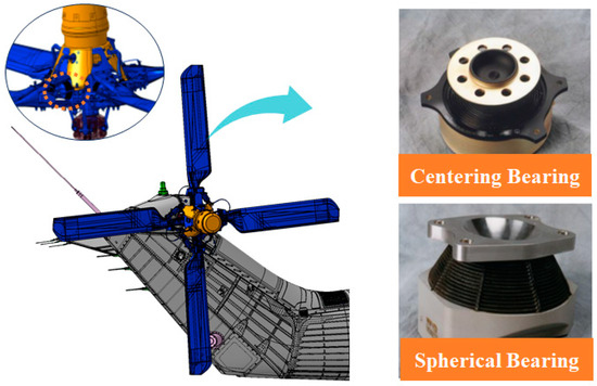
Figure 1.
Elastomeric bearing configuration of a helicopter hub.
As a related study, Schaffery and Skala [1] analyzed the effect of axial load on the behavior of the column consisting of a rubber layer and an alternative layer composed of curved or planar rigid cores and derived a finite difference equation governing the column response. Simo and Kelly [2] analyzed the stiffness properties of multilayer elastomer packages using them in the equation of motion of a single mass protected from low-frequency vibrations. Jeong et al. [3] introduced the character and shape of elastomeric bearings in next-generation helicopter hub systems and analyzed bearing-material requirements and measurement methods. Topkaya and Cem [4] conducted a parameter study using three-dimensional finite elements with geometric and material nonlinearity using Haringx shear weak column theory. Nasdala et al. [5] developed analytical design rules for bolt end plate connections with elastomeric intermediate layers and converted the actual stress distribution to equivalent average stress and associated effective heights. Kim et al. [6] analyzed the requirements of the elastomeric body bearing and lead-lag damper, which are helicopter rotor components. In particular, the characteristics of rubber materials that satisfy environmental requirements were also examined. Lee et al. [7] set the operating conditions of the elastomeric bearing to calculate the layered bottle rotation radius of the laminated rubber and calculated the nonlinear behavior and stress of the rubber material through finite element analysis. Kim et al. [8] are limited to the efficient design of spherical elastomeric bearings. A small model generation algorithm was developed, and the stiffness characteristics of a single rubber plate were analyzed. Kim et al. [9] summarized trends in the latest technology applied to non-bearing hub systems with the newest technology among helicopter hub systems. First, the advantages and disadvantages of each shape of the helicopter rotor hub system were analyzed, and the unique characteristics of the non-bearing rotor system compared to other hub systems were described. Vladimirs et al. [10] discussed the stiffness properties of the multilayer elastomer package alternately composed of thin metal layers and elastomer layers bonded by vulcanization or adhesives to design the package. Osgooei et al. [11] performed 3D parameter numerical finite element analysis (FEA) on 16 circular FREI bearings and compared the stress and strain predictions in the elastomeric layer. Gajewski et al. [12] applied the super-elastomeric compositional relationship for modeling elastomer bridge bearings and composed of two super-elastomeric models for materials such as rubber. Jin et al. [13] obtained several essential properties for the effect of blade flap-bending/torsion elastomeric coupling stiffness on blade root flap shear force and vibration hub load of bearingless rotors. Wei et al. [14] performed numerical analysis for monotonous shear tests to demonstrate the capacity of the proposed model in predicting the stress-strain relationship of elastomeric bearings at different strain rates and performed real-time hybrid simulation tests to investigate the accuracy and feasibility of the proposed model for seismic response evaluation applications in isolated bridges, resulting in good results. Zaimova et al. [15] investigated the effect of the accelerator-vaporizing system and vulcanization temperature on the mechanical and aging properties of vulcanization based on natural rubber/polybutadiene rubber (NR/BR) composites. Ahmadipour and Alam [16] conducted a sensitivity analysis on the mechanical properties of lead core rubber bearings (LCRB). The input variables included the number of rubber levels, lead core radius, and lead main material properties and were compared with the experimental results. Kalfas et al. [17] investigated the reaction of steel laminated elastomeric bearings under circulating shear and variable axial loads and analyzed their behavior better, focusing on tensile stress, stiffness, and dissipation capabilities in the elastomer. Rastgu and Konstantinidis [18] studied the effect of rotation on the horizontal behavior of elastomeric bearings using 3D finite element analysis (FEA). They observed that the configuration modeling assumption could significantly affect the results, especially at low perpendicular pressures where critical shear deformation is large. Schaffery [19,20] developed theoretical equations used in the next bearing sizing computer program for general three-dimensional loads and predicted beam-column motion and buckling for fairly common bearing geometry, loads, and deformation types, including shear, tensile, and bending. Kazeminezhad et al. [21] researched the effect of rotation on vertical stiffness using a nonlinear finite element program. It was observed that the perpendicular stiffness of the isolator may increase or decrease depending on the amount of rotation and the transverse displacement limit value. Nageswara et al. [22] presented a numerical study to explore the effect of the rigidity of elastomeric bearings on the dynamic behavior of railway bridges under train-induced vibration. Paulette et al. [23] investigated the adhesion behavior between the elastomer and the steel layer by performing a tensile test on a small square-shaped specimen instead of a shear test on a full-size insulator to analyze the effect of changes in the manufacturing process on isolator adhesion behavior. Fabio and Mirko [24] proposed an integrated nonlinear model of HDRB, including the cavitation of elastomers and post-cavitation. Mohammedmeki et al. [25] developed a three-dimensional model of steel-stacked bearing pads under various designated loads and constructed an experimental load-strain curve using the Ogden model, one of the built-in constituent models in ABAQUS software. Guojun et al. [26] investigated the mechanical properties (shortened final bearing capacity, failure mode) and reliability of the RSPB junction and studied the out-of-plane rotation performance using eight finite models. Erduran et al. [27] presented a numerical study to explore the effect of the rigidity of elastomeric bearings on the active behavior of railway links under train-induced vibration. Fink and Schatz [28] presented an integrated approach in which the elastomeric layer is applied to the primary and secondary composite sandwich panels and composite and titanium anti-monocoque panels within the prior structural arrangement. Galano and Calabrese introduced a precise solution to derive the vertical stiffness of the bearing as a function of horizontal displacement and calculated the vertical stiffness of the square-shaped FREI and the deformation of the effective compression modulus. Reith et al. [29] discussed the precision rating of bearings used in the aerospace industry, the overall quality of surface finishes and serious contact surfaces of bearings, lubricant selection, lubricant selection lubrication scheme, treatment of bearings, and integration into mechanisms. Wu et al. [30] proposed a method of predicting the force-displacement curve of the bridge ring restraint, and a new elastomeric bearing integrated within the steel ring restraint (EB-SRR) was designed to prevent the unseating of the bridge. Ahmed and Nicoleta [31] theoretically investigated the effect of the geometry of the elastomeric ring of the air journal bearing on the elastomeric ring dynamic coefficient. They discussed the physical finite element method (FEM) model used to obtain the dynamic coefficient of the ring.
This paper aims to verify the elastomeric bearing designed from the theoretical formula of the elastomeric bearing by finite element analysis. Compare and consider the results of comparing the stress state of the bearing for each behavior. In addition, by selecting the flight situation where the maximum load of the actual helicopter equipped with the elastomeric bearing can be applied, linear structural analysis and nonlinear analysis were performed to confirm the behavior of the elastomeric bearing.
To this end, elastomeric bearing modeling and effective finite element analysis techniques were presented. In addition, the core contents necessary for manufacturing reliable elastomeric bearings were described by analyzing the manufacturing process of elastomeric bearings. Mooney-Rivlin parameters will be offered based on the test results to predict the properties of the metal material and rubber laminated.
2. Characteristics of Elastomer
The recent development of elastomeric bearings and vibration insulators has reduced direct driving costs and reduced noise/vibration inside helicopters, as well as increased transportation capacity, enabling the production of quiet, comfortable, and reliable helicopters. In this section, the general features of elastomeric bearings used in helicopters will be discussed. A typical bearing supports the shaft while enabling continuous rotation. The elastomeric bearing may also generate rotational motion but is not continuous, and the motion is limited in the range of about 10° to 90°.
In addition, elastomeric bearings have several advantages over mechanical bearings.
The first stacking-type elastomeric bearing increases the stiffness effect and shows the characteristic of returning to the state before deformation when deformation is applied. Since the second elastomeric bearing does not have clearance, there is no increase in separation due to wear and tear, and no shaking due to chatter or separation occurs. Thus, smooth motion occurs until the end of the bearing’s life. A third maintenance cost can be reduced, and a brief inspection can be used to determine the availability. Table 1 categorizes the characteristics according to the shape of the helicopter hub, and Figure 1 shows that the elastomeric bearing is applied to the helicopter.

Table 1.
The Helicopter hub configuration and characteristics.
2.1. Design of Elastomeric Bearing
The required performance of the elastomeric bearing is divided into physical and environmental characteristics. Physical properties include rotational stiffness, compression stiffness, and fatigue analysis, and environmental characteristics should consider items related to material development, such as operating temperature, aging characteristics, and ozone resistance. Regarding material development, the required characteristics of the material should be identified. The behavioral characteristics of the mixed viscoelastomeric material by temperature, frequency, and amplitude should be considered, and experimental data should be used for the characteristics of the rubber material. When analyzing finite elements, the analysis is performed using the measured data. Finite element analysis was introduced to optimize the internal shape of the elastomeric bearing, and a laminated tube satisfying the required rigidity for optimization. It is intended to design a shape that can extend the bearing life by minimizing the stress acting on metal shim plate and viscoelastomeric materials. The design of the elastomeric bearing is determined by the following method:
- (a)
- Determination of external dimensions and target performance and rigidity
- (b)
- Selection of appropriate strain for marginal life expectancy
- (c)
- Calculation of apparent modulus of elastomericity between layers with marginal strain
- (d)
- Calculation of shape coefficient from shear modulus and apparent modulus of elastomericity of polymer materials
- (e)
- Calculation of Thickness of Interlayer Polymer Materials from Shape Coefficients
- (f)
- Calculation of strain for stiffness and operating spectrum from established thickness and physical properties
- (g)
- Detailed Design Using Target Performance Comparison and Finite Element Analysis
2.2. Laminated Rubber Properties of Elastomeric Bearing
The elastomeric bearing laminated rubber material was developed based on natural rubber. Natural rubber is a material obtained through a process of processing and collecting sap from a rubber tree called Hevea brasiliensis and consists of isoprene polymer [-[CH2-C (CH3)=CH-CH2)n]. It has excellent tactile and mechanical properties such as tensile strength, elongation. In addition, it is used in various fields because of its superior low-temperature properties (glass transition temperature −50 °C) that exert rubber elastomericity even at low temperatures compared to general synthetic rubber and its excellent properties such as processability and molding stability. As shown in Table 2, a physical property test was performed to develop a rubber material that meets the required performance of the elastomeric bearing, and the deformation of tensile, shear, and compression behavior was completed, and the data were used for finite element analysis.
Table 2.
Rubber material properties, Elastomeric bearing.
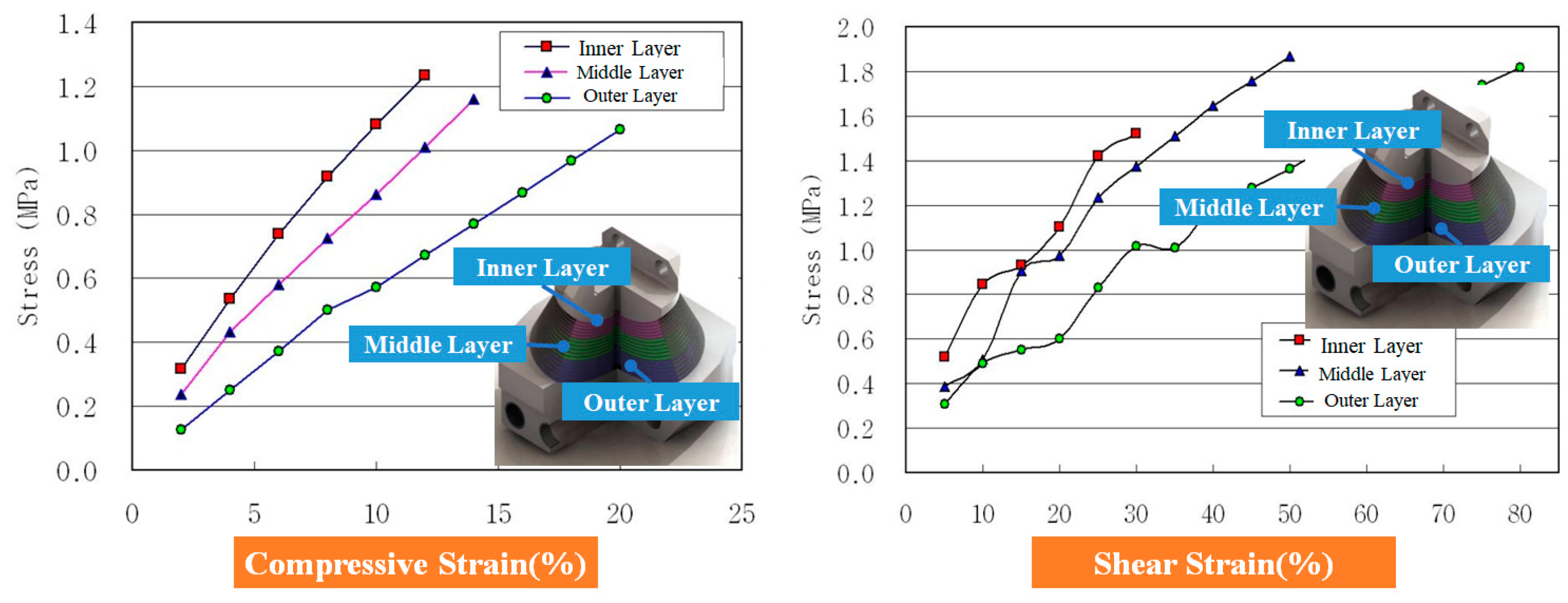
To obtain Young’s Modulus required for finite element analysis, the hardness value (Ha) of the rubber material applied with the elastomeric bearing was used by Equation (1), and it is the design value in Table 2. Equation (1) cites the experimental equation described in Engineering with Rubber. A cylindrical rubber test piece with a diameter of 10 mm and a height of 15 mm was manufactured using each elastomeric bearing to obtain compressive stress according to the compression rate of the height. A compression test was performed using 150 N in the test equipment and the test formula was the same as Equation (2). The test results are shown in Figure 2.
Here, F: Force, E: Young -Modulus, LM: Length of the Stoically Loaded Sample.
L0: Length of the Unloaded Sample, A0: Cross-Section of the Unloaded Sample.
HA: Hardness.
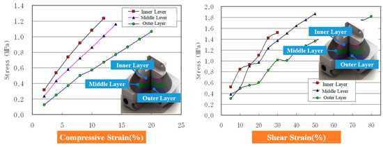
Figure 2.
Characteristic graph of compressive and shear stress of rubber with elastomeric bearing.
Figure 2.
Characteristic graph of compressive and shear stress of rubber with elastomeric bearing.
2.3. Manufacturing Process of Elastomeric Bearing
In a dehydrated state, a primer is first applied to adhere the metal plate to rubber, dried, and then a rubber-metal adhesive is applied to the part’s surface to a uniform thickness, as shown in Figure 3a. When the adhesive drying is completed, the altar work of the applied rubber is carried out. Since the used rubber is made into a plate shape, it is cut by each size, as shown in Figure 3b. Preheat the rubber to make it flexible before lamination. If the temperature and time are exceeded, a defect may occur in which molding is completed before the rubber is vulcanized, so special attention is required. When the preparation of the parts and the application rubber is completed, the lamination of each layer is carried out, as shown in Figure 3c,d. In the lamination, a lamination plate and a rubber plate are alternately stacked on each layer to be in the correct position for the pin at the center. After lamination is completed, it is performed at about 70 °C for 30 min through a preheater. The purpose of preheating is to prevent rubber adhesion and product defects due to the high vulcanization temperature of the rubber and the temperature difference between the inside and outside of the molding rubber, that is, the temperature conduction time difference between the molding mold and the product. First, preheating of the molding mold is required to manufacture the elastomeric bearing. Preheating is mounted on a compression press so that the mold is sufficiently preheated at 130 °C. Figure 3f shows the mold preheating in the press. Fit a bearing laminated to a sufficiently preheated molding mold. When installing, be careful not to move the laminated area, and since the molding mold is high, pay attention to the image. Do not take long to install. Figure 3g is a state attached to a molding mold. When the elastomeric bearing was completely installed, it was continued for 90 min at 130 °C, the vulcanization temperature of the applied rubber, using a tool. At the beginning of compression, air removal was performed ten times to remove residual air from the inside. Air removal is caused by air bubbles generated by internal residual air, and stress concentration is generated at the area where air bubbles are generated after rubber molding, resulting in a short circuit, and causing defects in the product.
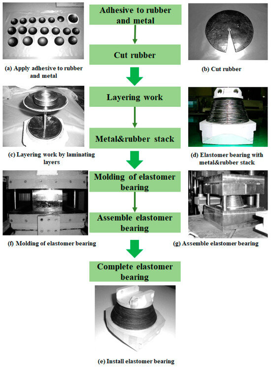
Figure 3.
Manufacturing process of elastomeric bearing.
3. Design of Elastomeric Bearing Considering Large Load and Nonlinear Motion
3.1. Configuration of Elastomeric Bearing
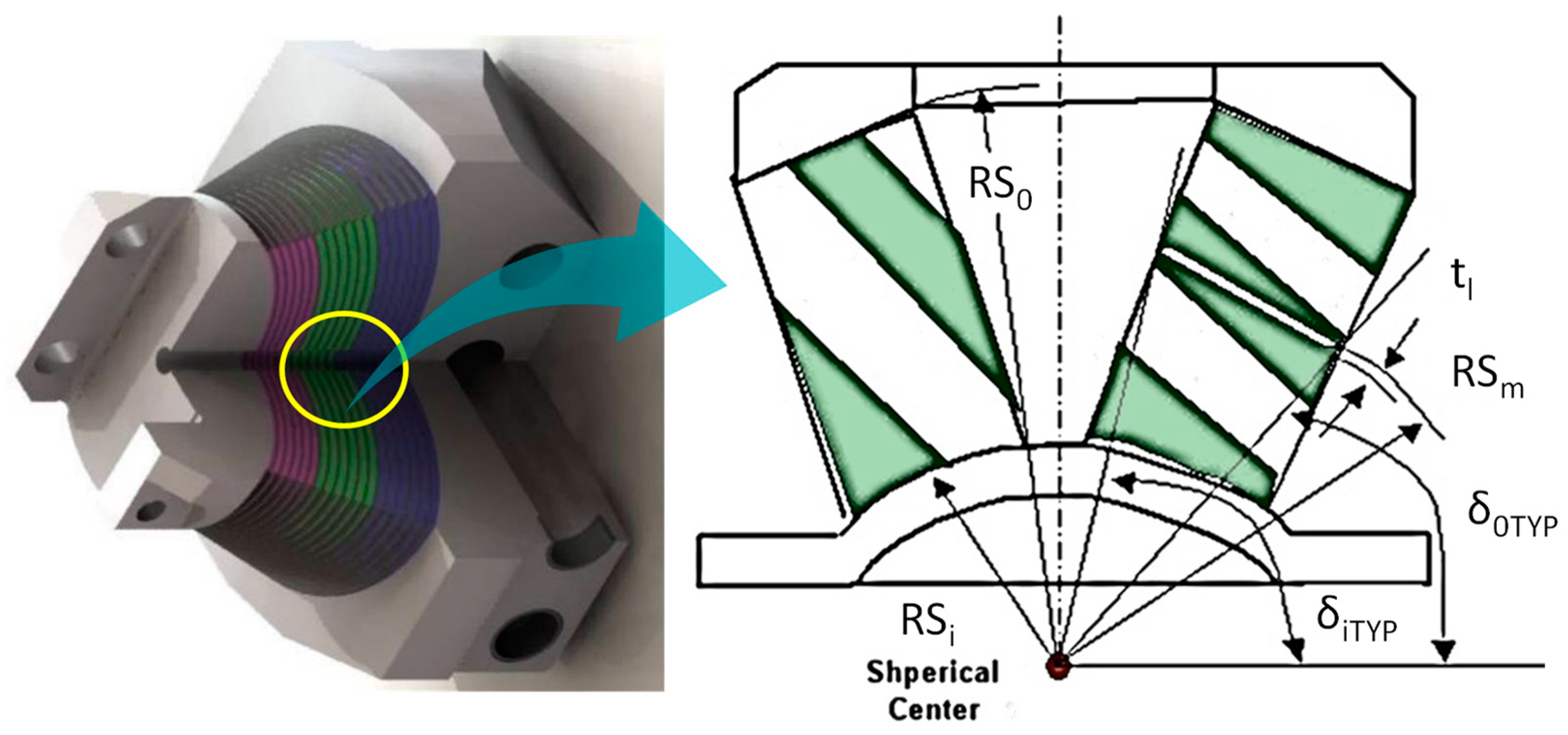
The elastomeric bearing is connected to the blade, resulting in a centrifugal force load on the blade. If this centrifugal force acts as a tensile load on the elastomeric bearing, there is a very high risk of peeling, so when operating on the rotor system, a compression load must be designed to act. Figure 4 is a conceptual diagram of elastomer bearings, and RS0, RSi, RSm, δTYP, and δ0TYP, which are set as variables to meet the design, are set as basic design variables. Stack rubber was divided into three stages: inner, middle, and outer, and the radius of rotation and thickness of each layer are shown in Table 3. The thickness of the metal shim plate is set to 1 mm, and as a result, an elastomeric bearing with 18 layers of stacked rubber plates and 17 layers of metal shim plates is designed.

Figure 4.
A design concept of elastomeric bearing.
Table 3.
Radius of rotation of elastomeric bearing.
The elastomeric bearing shall be rigid, as well as the maximum displacement for each movement. It affects not only the vibration characteristics of the rotor system but also the maneuverability. In general, bending stiffness around the x-axis and tensile stiffness around the y- and z-axes are defined as minimum values. Rubber components generally have different performances depending on temperature conditions. Performance should not change to a certain level, even under high- or low-temperature conditions.
3.2. Calculation Mooney-Rivlin Constant Value of Laminated Rubber
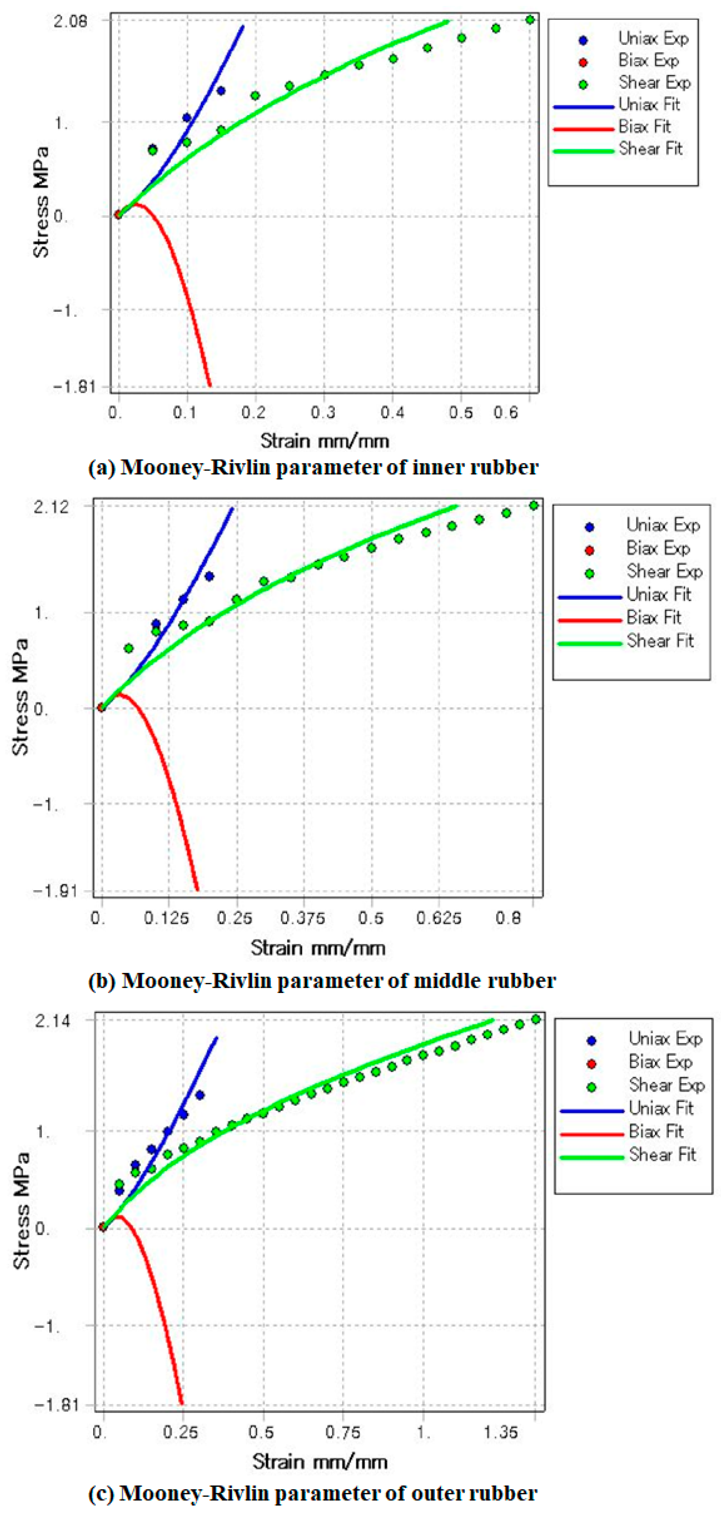
A strain energy function based on hyperelastomericity theory can be used for finite element analysis of elastomers. Superelastomericity theory describes the behavior of elastomeric bodies utilizing the concept that the strain of the strain energy function per unit volume is the same as that of stress, and the Mooney-Rivlin model was used in this study [32]. In the case of the Mooney-Rivlin model, it is extensively used in the finite element analysis of elastomers due to its mathematical simplicity and the physical meaning of its coefficient. The 3-parameter Mooney-Rivlin model applied to this analysis is expressed as Equation (3), where it is.
In Equation (3), it is the constant of the Kirchhoff stress tensor and is the main constant of the Couchy-Green strain tensor. To apply the Mooney-Rivlin model to finite element analysis, the material constant Mooney-Rivlin parameters (C10, C01, C11, d) must be determined, as shown in Table 4 and Figure 5. For the material properties of laminated rubber, the test values described in Section 2.1 were applied. By using the measured tensile stress and shear stress data, the Mooney-Rivlin coefficient of applied rubber, a nonlinear material, was obtained and analyzed.
Table 4.
Mooney-Rivlin Parameters.
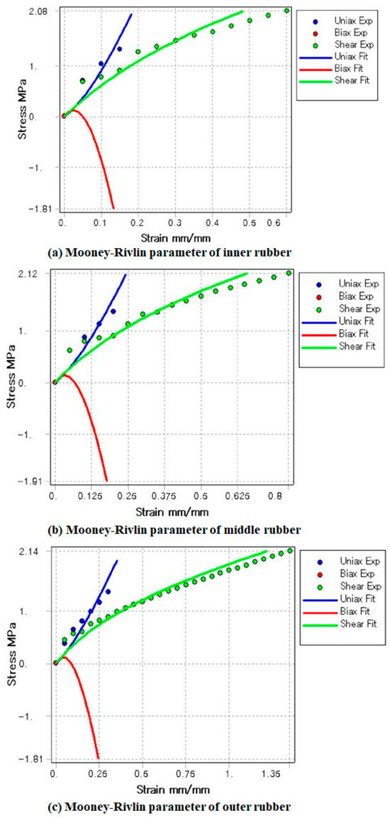
Figure 5.
Mooney-Rivlin properties of elastomeric bearing.
3.3. Sizing Equation of Elastomeric Bearing Structure
Through Equation (4), the compressive strain and compressive stress of the elastomeric bearing can be determined.
The ratio of the spring in the axial direction is shown in Equation (5).
Here, δi: Angle from horizontal to inner diameter, deg;
εmax: 150~250% at static limit motion, tR: rubber thickness;
TR: Total rubber thickness, εmax: Compression strain, FA: Axial force;
Ec: Static compression modulus, KA: Axial spring rate, σc: Compression stress;
RS: Spherical radius.
The ratio of torsion and cocking spring can be expressed by Equations (6) and (7).
Here, δO: Angle from horizontal to outer diameter, deg
The shear strain due to torsion is the same as Equation (8), and the shear strain due to cacking is the same as Equation (9). For elastomeric bearings, the strain due to torsion and caulking is set as an important factor in the design.
The shear strain due to the pitch angle of the blade is shown in Equation (10).
The selection of the size of the elastomeric bearing is proportional to the mass of the helicopter, the number of blades, and the caulking angle. Equation (11) is an empirical equation as follows.
Here, M is helicopter mass, n is number of blades, β0 is coning angle.
4. Structural Analysis of Elastomeric Bearing
4.1. Structural Analysis Results of Elastomeric Bearing
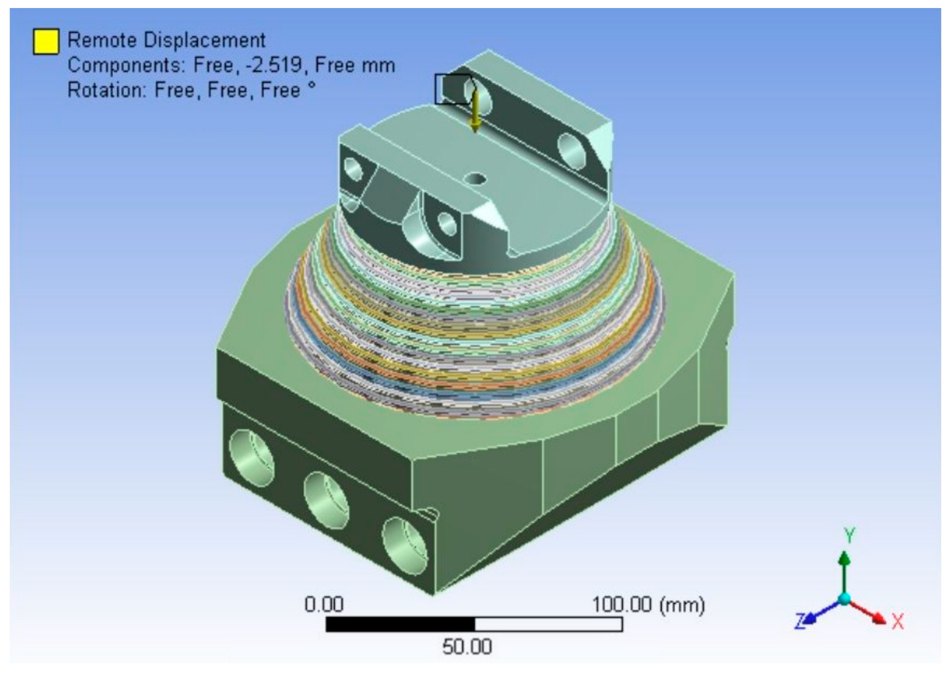
The diameter of the bearing was calculated to be 153.98 mm and determined to be 154 mm. In the design of the elastomeric bearing, the laminated rubber was divided into three stages: inner, middle, and outer, each of which consisted of a total of 18 layers, and the thickness of the laminated rubber was 1.4 mm for the inner, 1.8 mm for the middle, and 2.0 mm for the outer. Ansys, a general-purpose finite element analysis program, was used to interpret the main elements of elastomer bearings and maintain consistency with existing analysis results. Figure 6 shows the shape of the designed elastomer bearing. The design values described in Chapter 3 were applied to the material properties of laminated rubber. The essential value of Aluminum Alloy provided by Ansys was used for the metal shim plate. For the accuracy of the analysis, a three-dimensional structural solid was used as the SOLID 197 element. The element network size was automatically created, the number of nodes was 198,970, and the total number of elements was 91,569. Figure 7 represents the generated finite element model. As for the boundary conditions, the lower part of the model was fixed, as shown in Figure 7. A design displacement of 2.52 mm was given to the upper surface in the direction of the Y-axis of the vertical displacement of the elastomeric bearing, and the reaction force value was obtained and compared with the design load value. The analyzed reaction force value for vertical displacement was 226,180 N, which was interpreted to be about 1.77 times smaller than the design load of 400,000 N. Figure 8 shows the max displacement of the elastomeric bearing when the centrifugal force of the helicopter blade is applied. A significant amount of displacement occurred due to the nature of Shim, which overlaps rubber and metal materials. This is because the displacement of rubber is much larger than that of metal materials. Figure 9 shows the strain received by the elastomeric bearing due to compressive stress. It can be seen that the flexible body bearing secures a structural safety margin of the metal material when the axial load is applied.
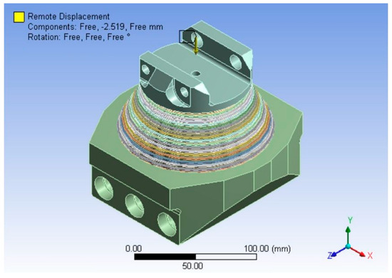
Figure 6.
Design model with axial vertical displacement.
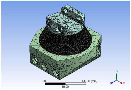
Figure 7.
Single finite element model of elastomeric bearing.
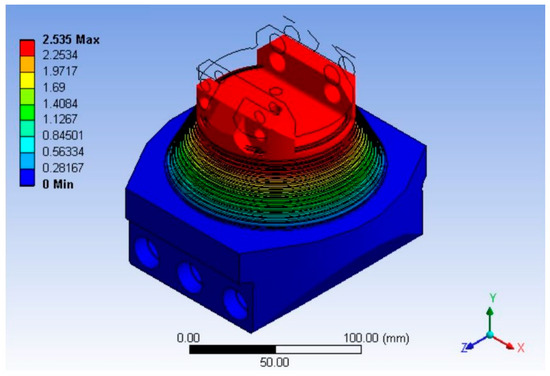
Figure 8.
Deformation with axial vertical displacement of elastomeric bearing.
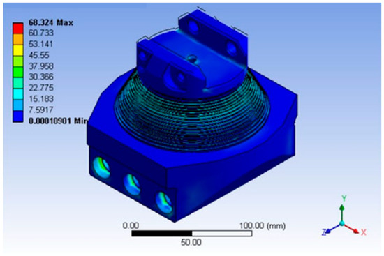
Figure 9.
Strain with axial vertical displacement of elastomeric bearing.
4.2. Structural Analysis Results of Elastomeric Bearing in Helicopter Flight Environment
In this section, a static structural analysis was performed by simulating the flight situation of an actual helicopter equipped with an elastomeric bearing. The elastomeric bearing is a structure fastened with a tail rotor blade and a pin, and a finite element model was constructed by dividing the contact conditions of the blade, creation pin, and elastomeric bearing body into bonding conditions and contact conditions. The condition at the time of contact here applies the coefficient of friction of 0.1. The elastomeric bearing is kept aligned with the axis of the rotor blade. The internal member composed of rubber and steel is attached to the tail rotor hub, and during rotor spin-up, the bearing is compressed by centrifugal force. The centrifugal force of the rotor blade is applied to the rotor hub, and the rotor blade pitch induces twisting in the bearing. The blade flap cocks the bearing from the vertical plane, and the blade drag (lead-lag) cocks the bearing. Finite element analysis is performed using the assembly model shown in Figure 10. Figure 10 constructs a three-dimensional finite element model in a helicopter flight environment. Here, Shim is laminated with metal material and rubber, and the rest of the structure is made of aluminum. Figure 11 and Table 5 include the boundary conditions when the finite element model is constructed as an assembly. In Table 5, the Bonded condition means that the finite element model is integrally configured, and the friction coefficient of 0.1 means that frictional force is generated in the vertical direction at the structure interface.

Figure 10.
Finite element model of elastomeric bearing in helicopter flight environment.

Figure 11.
Boundary condition of elastomeric bearing in helicopter flight environment.
Table 5.
Boundary conditions for rotor blade, fitting and elastomeric bearing structures.
Case 1: The axial centrifugal force of the blade is applied to a boundary condition, and the displacement in the Y and Z directions is zero.
Case 2: Flap moment is applied to the hub, displacement in the Z direction is 0, and displacement by Flap in the X and Y directions is input.
Details of the model and boundary conditions are shown in Figure 11. The structural analysis conditions in the x-direction of the elastomeric bearing mounted on the helicopter were divided into a combination of axial force and angle in the axial direction. The maximum flight load condition was set at 2200 N and 16 degrees in the flap angle when the helicopter flew. When constructing the finite element model, the interference fitness of the bushing to the external member was modeled as maximum radial interference (0.00125 in) and established that the effect of the pitch on the stress was negligible at the critical position. The impact of lead-lag is expected to be minor, and the current model excludes lead-lag dampers.
If the results of Figure 6, Figure 7, Figure 8 and Figure 9 were the result of finite element analysis for a single piece of elastomeric bearing, Figure 10 and Figure 11 are finite element models for assembling elastomeric bearings mounted on rotor blades. Because it is mounted on the rotor blade, centrifugal force, flap moment, and lead-lag moment are simultaneously applied. In addition, there is a difference between the behavior and strength of the single elastometric bearing because it interacts with the rotor blade.
Figure 12a illustrates the general situation when a helicopter is flying by entering a displacement with a slight angle with centrifugal force. Figure 12b shows the situation when the helicopter is flying with significant behavior and load by entering large centrifugal forces and the most significant displacement and angle. The load case has the most extensive behavior when the flap angle is 16 degrees. At this time, structural soundness was evaluated through the results of finite element analysis.
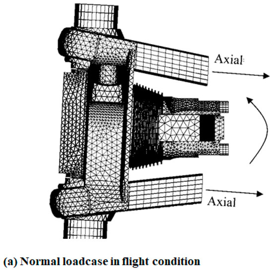
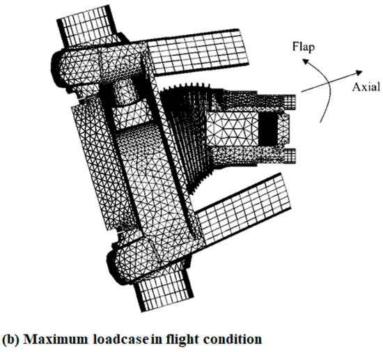
Figure 12.
Maximum loadcase of elastomeric bearing in helicopter flight environment.
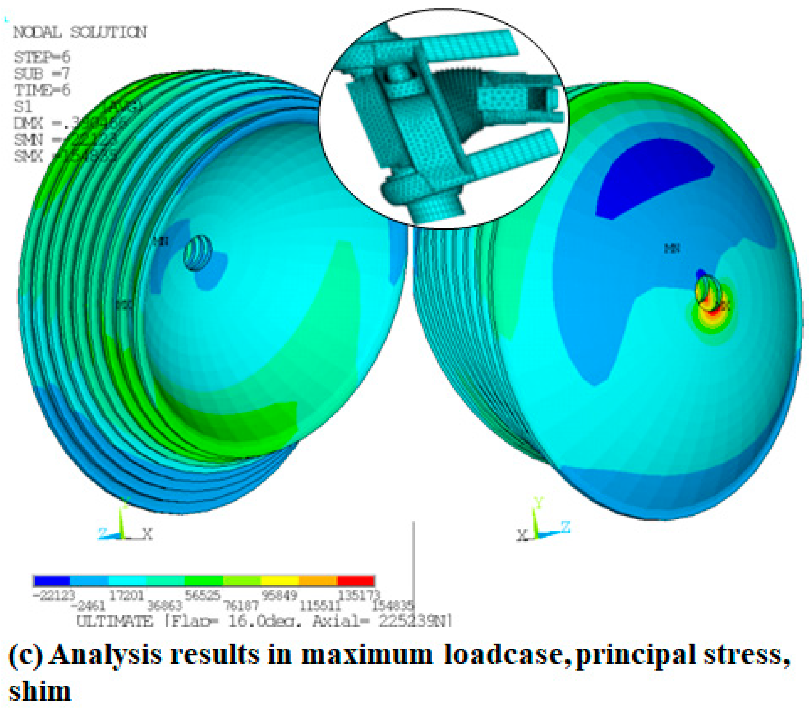
In Figure 13, when the elastic bearing was mounted on the blade assembly, the maximum stress result was obtained under the most significant flight load condition: the centrifugal force of 225,000 N and the Flap angle of 16 degrees. Figure 13a is the stress result of the static analysis of the external member of the elastic bearing. Aluminum 7075 is applied to the material of the exterior member. As a result of comparing the maximum stress, it can be seen that there is a margin of 23.5% at 52,361 psi (523 MPa). Figure 13b is an inner member of the elastic bearing and performs static analysis under maximum load conditions to obtain a stress value of 68,025 psi (469 MPa) above the allowable value. Since the tolerance was 448 MPa, a margin of −4% was calculated. Unlike linear analysis, nonlinear analysis often combines the assembly material’s nonlinearity, frictional force, and geometric nonlinearity to calculate a low strain. When the strain value was calculated by performing a nonlinear analysis, as shown in Figure 13b, a 6676 microstrain was obtained at the lower corner of the inner member. The allowable value of the nonlinear strain of Al 7075 is 60,000 microstrain, and a margin of 700% or more is calculated compared to when the static analysis was performed. Figure 13c shows the stress of 154 MPa in the shim part with the largest inner diameter when the metal and rubber are stacked, and the maximum centrifugal force is applied to the flap angle of 16 degrees. The allowable value of shim is 155 MPa, which has a margin of 0.006 and is robust under maximum load conditions.
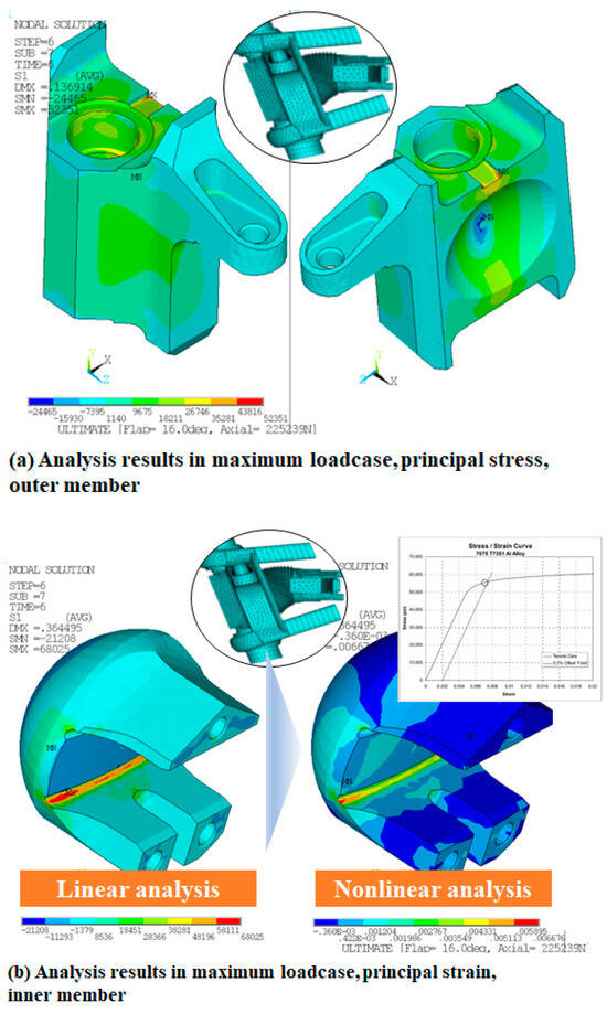
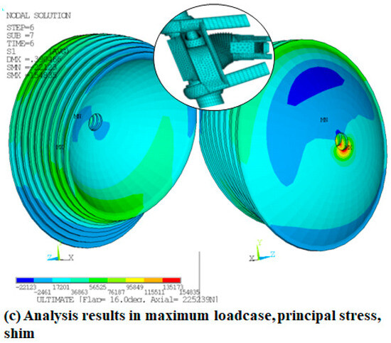
Figure 13.
Analysis results in maximum loadcase, principal stress.
4.3. Nonlinear Motion Results of Elastomeric Bearing
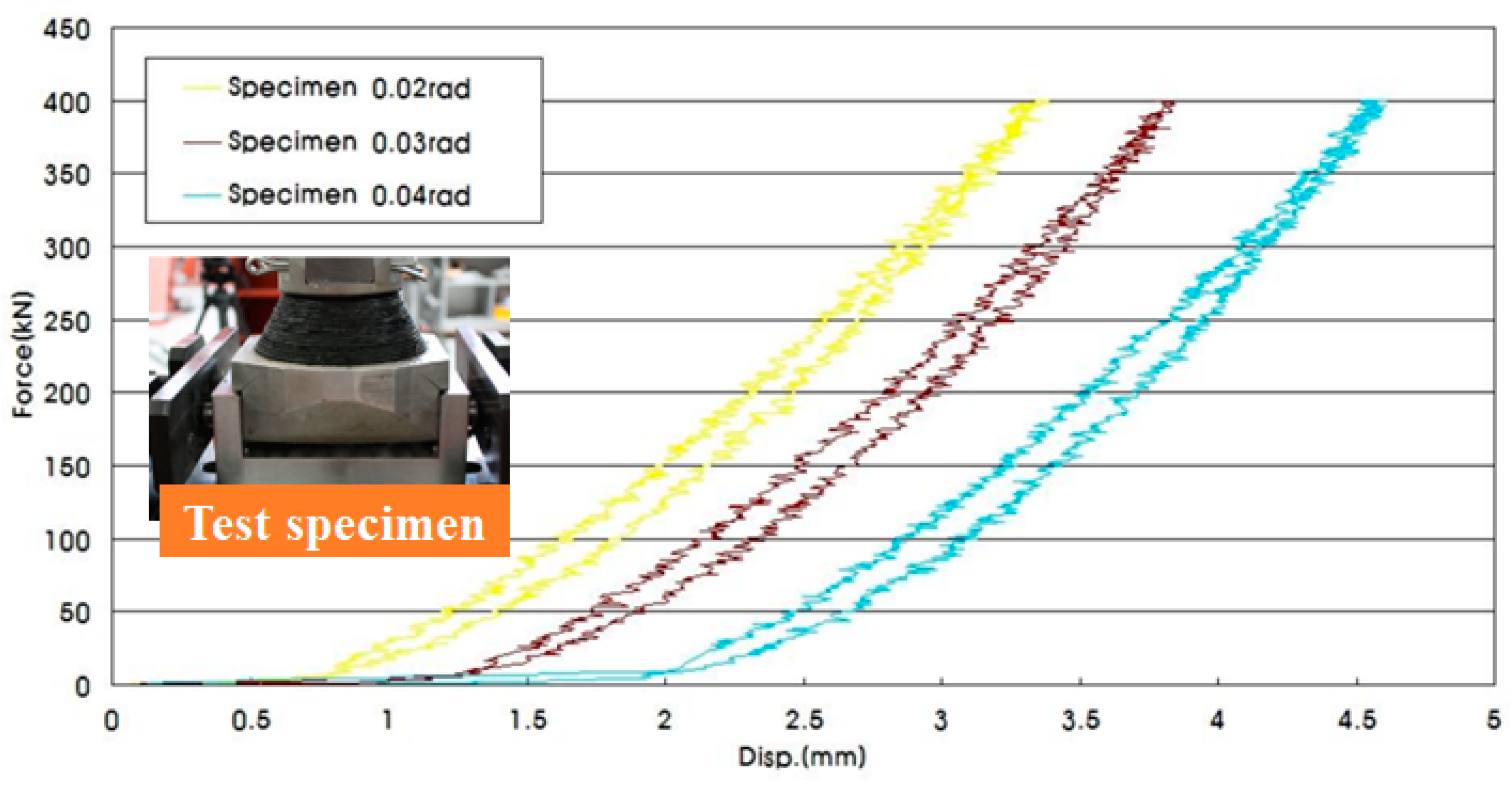
A design load of 400 kN is compressed at an angle of 0.02, 0.03, and 0.04 rad at a speed of 0.02 MN/s. When the test equipment comes into contact with the side during vertical compression, it rotates in one direction of the elastometric bearing at a certain angle. In this rotating state, the design load is applied. Figure 14 is the result of outputting the displacement when compressed according to each rotation angle according to the type of elastometric bearing. The vertical displacement amount varies in degree but tends to increase as the rotation angle of the elastometric bearing increases. It indicates that the larger the rotation angle at a constant load, the greater the amount of deformation. After the end of the test, the appearance dimensions of each elastometric bearing should be checked to confirm that it is the same as the initial dimensions.

Figure 14.
Compression rotation test results by elastometric bearing angle.
5. Conclusions
In this paper, the manufacturing process of elastomeric bearings was analyzed to describe the essential contents necessary for reliable elastomeric bearings. Mooney-Rivlin parameters were presented based on the test results to predict the characteristics of metal materials and rubber stacked. Through finite element analysis, a single elastomeric bearing reflecting the characteristics of Mooney-Rivlin parameters was used to determine whether the structure was abnormal. In addition, the flight situation in which the maximum load of an actual helicopter equipped with an elastomeric bearing can be applied was selected, and linear structural analysis and nonlinear analysis were performed to confirm the behavior of the elastomeric bearing.
In the stress result of linear static analysis, a −4% margin was calculated, but the margin of the strain analysis result in nonlinear analysis was secured more than 700%, confirming the robustness of the structure.
Applying elastomeric bearing technology to existing metal material bearings and hydraulic damper parts can reduce maintenance costs and increase safety. It was shown that design reliability for the molding and manufacturing process of the elastomeric bearing can be improved by establishing a design and analysis technique that can meet the structural rigidity and strength requirements of the elastomeric bearing, a vital component of the helicopter main rotor system, and optimizing the material applying the elastomeric bearing.
Author Contributions
Methodology, J.-H.J.; Software, J.-H.J.; Validation, J.-H.J.; Writing—original draft, J.-H.J.; Writing—review & editing, S.-H.A.; Visualization, J.-H.J.; Project administration, S.-H.A. All authors have read and agreed to the published version of the manuscript.
Funding
This research was funded by Shinhan University Research Fund, grant number [2022-005].
Institutional Review Board Statement
Not applicable.
Informed Consent Statement
Not applicable.
Data Availability Statement
The data presented in this study are available in article.
Conflicts of Interest
The authors declare no conflict of interest.
References
- Schapery, R.A.; Skala, D.P. Elastomeric stability of laminated elastomeric columns. Int. J. Solids Struct. 1976, 12, 401–417. [Google Scholar] [CrossRef]
- Simo, J.C.; Kelly, J.M. Finite element analysis of the stability of multilayer elastomeric bearings. Eng. Struct. 1984, 6, 162–174. [Google Scholar] [CrossRef]
- Jeong, J.-G.; Kim, Y.-S.; Park, G.-R.; Kim, D.-H.; Lee, M.-G.; Kim, D.-K. An Experimental Study for Material Properties of Elastomer Bearing Using Next Genration Helicopter Rotor System; Korean Society for Noise and Vibration Engineering (KSNVE): Seoul, Republic of Korea, 2003. [Google Scholar]
- Topkaya, C. Analysis of specimen size effects in inclined compression test on laminated elastomeric bearings. Eng. Struct. 2004, 26, 1071–1080. [Google Scholar] [CrossRef]
- Nasdala, L.; Hohn, B.; Rühl, R. Design of end-plate connections with elastomeric intermediate layer. J. Constr. Steel Res. 2007, 63, 494–504. [Google Scholar] [CrossRef]
- Taeju, K.; Seungho, K.; Inhui, H.; Gyeongmun, B.; Jeongho, H. Establishment elastomer bearing & lead-lag damper requirements for helicopter main rotor. Int. J. Aeronaut. Space Sci. 2008, 731–734. [Google Scholar]
- Lee, W.-H.; Lim, H.-J.; Jo, H.-J.; Oh, J.; Park, K.-R. A Study on The Shape Design and Finite Element Analysis of Elastomer Bearing for Helicopter Rotor System; The Korean Society for Aeronautical & Space Sciences: Seoul, Republic of Korea, 2008. [Google Scholar]
- Kim, H.D.; Yoo, S.Y.; Park, J.S. Design of an Elastomeric Bearing for a Helicopter Rotor Hub by Non-linear Finite Element Method. J. Korean Soc. Aeronaut. Space Sci. 2010, 38, 612–619. [Google Scholar]
- Kim, D.K.; Yun, C.Y.; Song, K.W.; Kim, S.B.; Kim, S.H. Current Technology Status of Bearingless Rotor Hub system for Helicopter. Curr. Ind. Technol. Trends Aerosp. 2010, 8, 118–130. [Google Scholar]
- Gonca, V.; Polukoshko, S.; Boyko, A. Analytical and Experimental Research of Compressive Stiffness for Laminated Elastomeric Structures. Procedia Eng. 2014, 69, 1388–1396. [Google Scholar] [CrossRef]
- Osgooei, P.M.; Tait, M.J.; Konstantinidis, D. Three-dimensional finite element analysis of circular fiber-reinforced elastomeric bearings under compression. Compos. Struct. 2014, 108, 191–204. [Google Scholar] [CrossRef]
- Gajewski, M.; Szczerba, R.; Jemioło, S. Modelling of Elastomeric Bearings with Application of Yeoh Hyperelastomeric Material Model. Procedia Eng. 2015, 111, 220–227. [Google Scholar] [CrossRef]
- Jin, Y.; Yu, L.; Yong, L. Vibration Reduction of a Bearingless Helicopter Rotor with Composite Tailored Couplings. Procedia Eng. 2015, 99, 1372–1379. [Google Scholar] [CrossRef]
- Wei, W.; Yuan, Y.; Igarashi, A.; Tan, P.; Iemura, H.; Zhu, H. A generalized rate-dependent constitutive law for elastomeric bearings. Constr. Build. Mater. 2016, 106, 693–699. [Google Scholar] [CrossRef]
- Zaimova, D.; Bayraktar, E.; Miskioglu, I. Design and manufacturing of new elastomeric composites: Mechanical properties, chemical and physical analysis. Compos. Part B Eng. 2016, 105, 203–210. [Google Scholar] [CrossRef]
- Ahmadipour, M.; Alam, M.S. Sensitivity analysis on mechanical characteristics of lead-core steel-reinforced elastomeric bearings under cyclic loading. Eng. Struct. 2017, 140, 39–50. [Google Scholar] [CrossRef]
- Kalfas, K.N.; Mitoulis, S.A.; Katakalos, K. Numerical study on the response of steel-laminated elastomeric bearings subjected to variable axial loads and development of local tensile stresses. Eng. Struct. 2017, 134, 346–357. [Google Scholar] [CrossRef]
- Rastgoo, M.S.; Konstantinidis, D. Finite element study of the effect of support rotation on the horizontal behavior of elastomeric bearings. Compos. Struct. 2017, 163, 474–490. [Google Scholar] [CrossRef]
- Schapery, R.A. Elastomeric bearing sizing analysis Part 1: Spherical bearing. Int. J. Solids Struct. 2018, 152–153, 118–139. [Google Scholar] [CrossRef]
- Schapery, R.A. Elastomeric bearing sizing analysis Part 2: Flat and cylindrical bearings. Int. J. Solids Struct. 2018, 152–153, 140–150. [Google Scholar] [CrossRef]
- Kazeminezhad, E.; Kazemi, M.T.; Mirhosseini, S.M. Assessment of the vertical stiffness of elastomeric bearing due to displacement and rotation. Int. J. Non-Linear Mech. 2020, 119, 103306. [Google Scholar] [CrossRef]
- Nageswara Rao, P.; Manoj Kumar, N.; Padmanaban, S.; Subathra, M.S.P.; Chand, A. A Novel Sensorless Approach for Speed and Displacement Control of Bearingless Switched Reluctance Motor. Appl. Sci. 2020, 10, 4070. [Google Scholar] [CrossRef]
- Pauletta, M.; Pinzano, F.; Frappa, G.; Russo, G. Tensile Tests for the Improvement of Adhesion between Rubber and Steel Layers in Elastomeric Isolators. Appl. Sci. 2020, 10, 8063. [Google Scholar] [CrossRef]
- Mazza, F.; Mazza, M. Influence of Elastomeric Bearings in Tension on the Seismic Performance of Base-Isolated r.c. Buildings. Appl. Sci. 2021, 11, 82. [Google Scholar] [CrossRef]
- Mohamedmeki, Z.M.; Esmail, F.J.; Ajeel, E.A. Fatigue life analysis of laminated elastomeric bearing pad. Mater. Today Proc. 2021, 42, 2361–2368. [Google Scholar] [CrossRef]
- Sun, G.; Wu, M.; Yang, Y.; Xue, S. Mechanical properties of radial spherical plain bearing (RSPB) joint with an inserted plate for building structural application—An experimental study. Structures 2021, 33, 2140–2151. [Google Scholar] [CrossRef]
- Erduran, E.; Nordli, C.; Gonen, S. Effect of Elastomeric Bearing Stiffness on the Dynamic Response of Railway Bridges Considering Vehicle. Bridge Interact. 2022, 12, 11952. [Google Scholar] [CrossRef]
- Fink, A.; Schatz, R. Structurally integrated constrained layer damping for noise reduction on sandwich and semi-monocoque helicopter structures. Compos. Struct. 2023, 322, 117354. [Google Scholar] [CrossRef]
- Rejith, R.; Kesavan, D.; Chakravarthy, P.; Narayana, M.S. Bearings for aerospace applications. Tribol. Int. 2023, 181, 108312. [Google Scholar] [CrossRef]
- Wu, H.; Wang, Z.; Zhang, Q.; Sui, W. Mechanical performance of an elastomeric bearing incorporated within steel ring restrainers. Structures 2023, 52, 117–130. [Google Scholar] [CrossRef]
- Paridie, A.; Ene, N. Theoretical study of effect of the geometrical parameters on the dynamic properties of the elastomeric rings of an air journal bearing. Heliyon 2023, 9, 16129. [Google Scholar] [CrossRef]
- Rivlin, R.S. Large elastomeric deformations of isotropic materials IV. Further develpments of the general theory. Phil. Trans. A 1948, 241, 379–397. [Google Scholar]


Disclaimer/Publisher’s Note: The statements, opinions and data contained in all publications are solely those of the individual author(s) and contributor(s) and not of MDPI and/or the editor(s). MDPI and/or the editor(s) disclaim responsibility for any injury to people or property resulting from any ideas, methods, instructions or products referred to in the content. |
© 2023 by the authors. Licensee MDPI, Basel, Switzerland. This article is an open access article distributed under the terms and conditions of the Creative Commons Attribution (CC BY) license (https://creativecommons.org/licenses/by/4.0/).