
Study on Collection Performance of Hydraulic Polymetallic Nodule Collector Based on Solid–Liquid Two-Phase Flow Numerical Simulation

Abstract
:1. Introduction
2. Hydraulic Collector
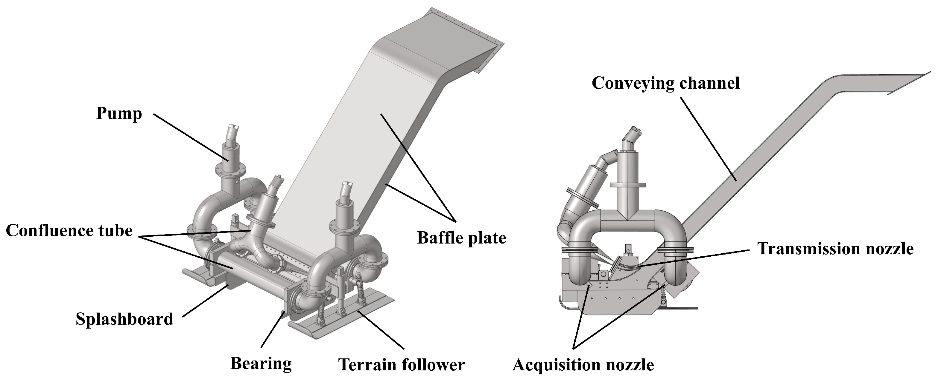
2.1. Structural Composition
2.2. Operating Principle
3. Numerical Method and Validation
3.1. Governing Equation
3.2. Modeling
3.2.1. Model Simplification
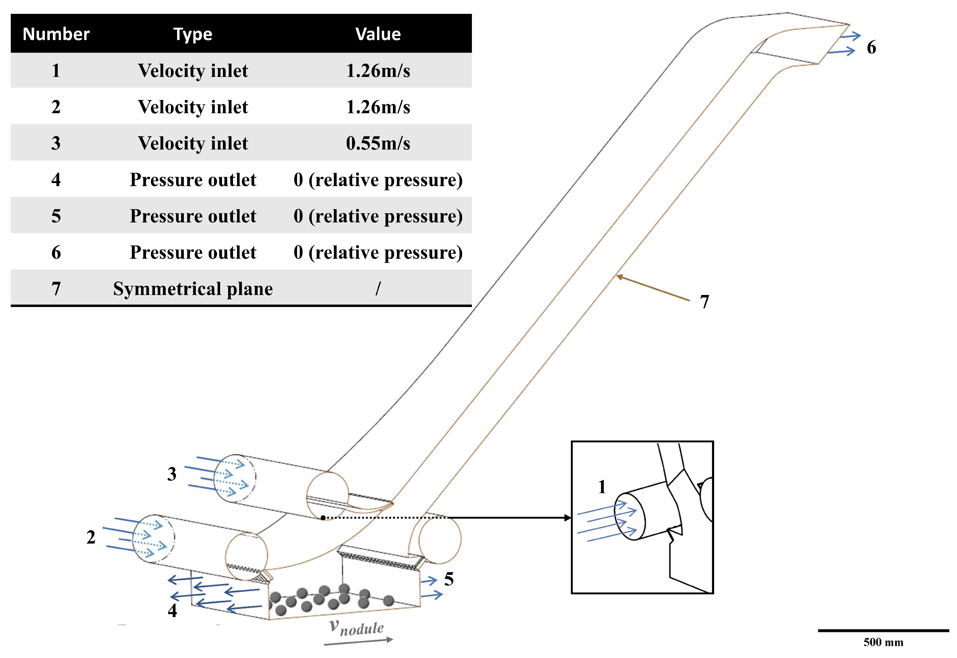
3.2.2. Model Setting
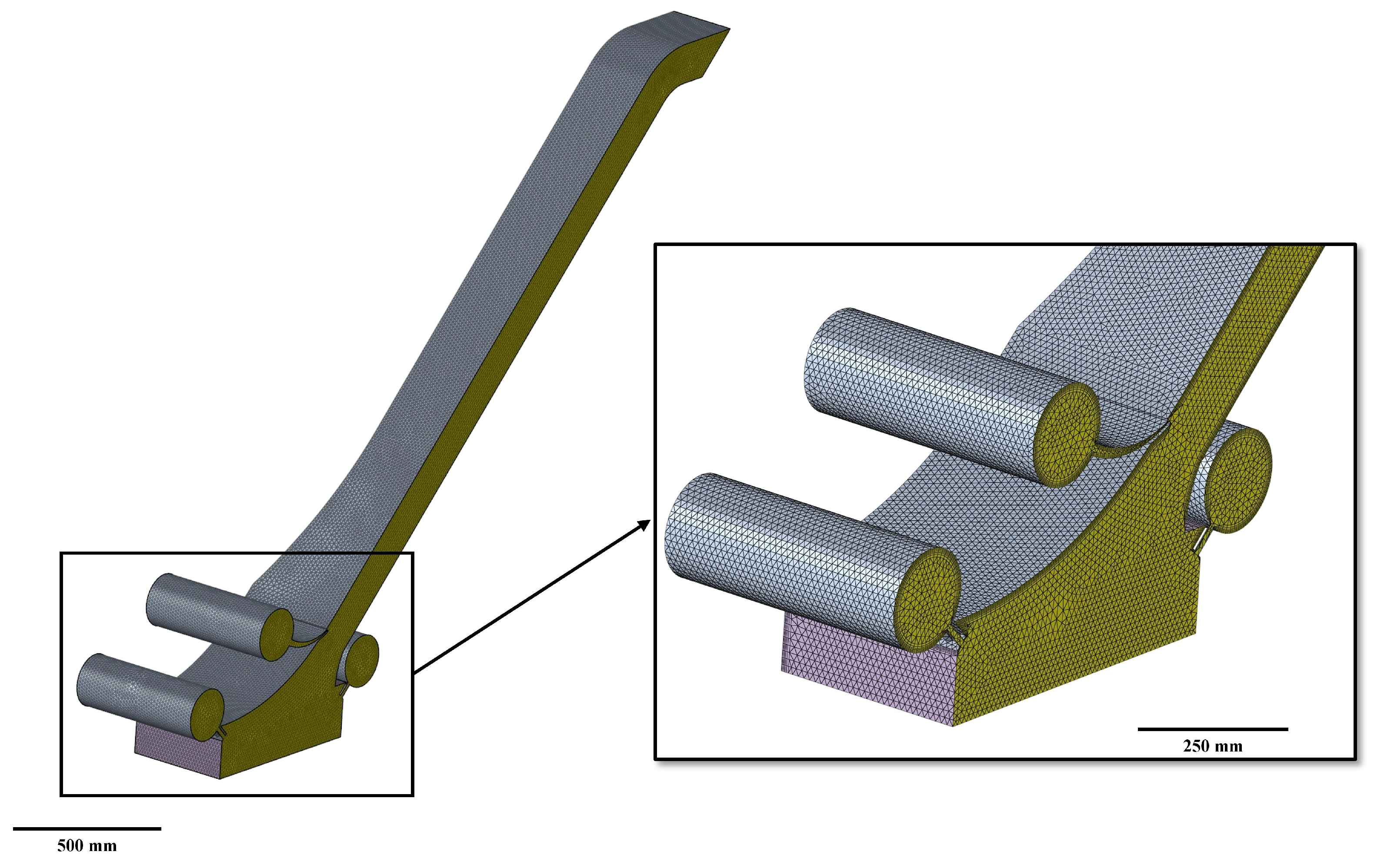
3.2.3. Mesh Independence Study
3.3. Validation
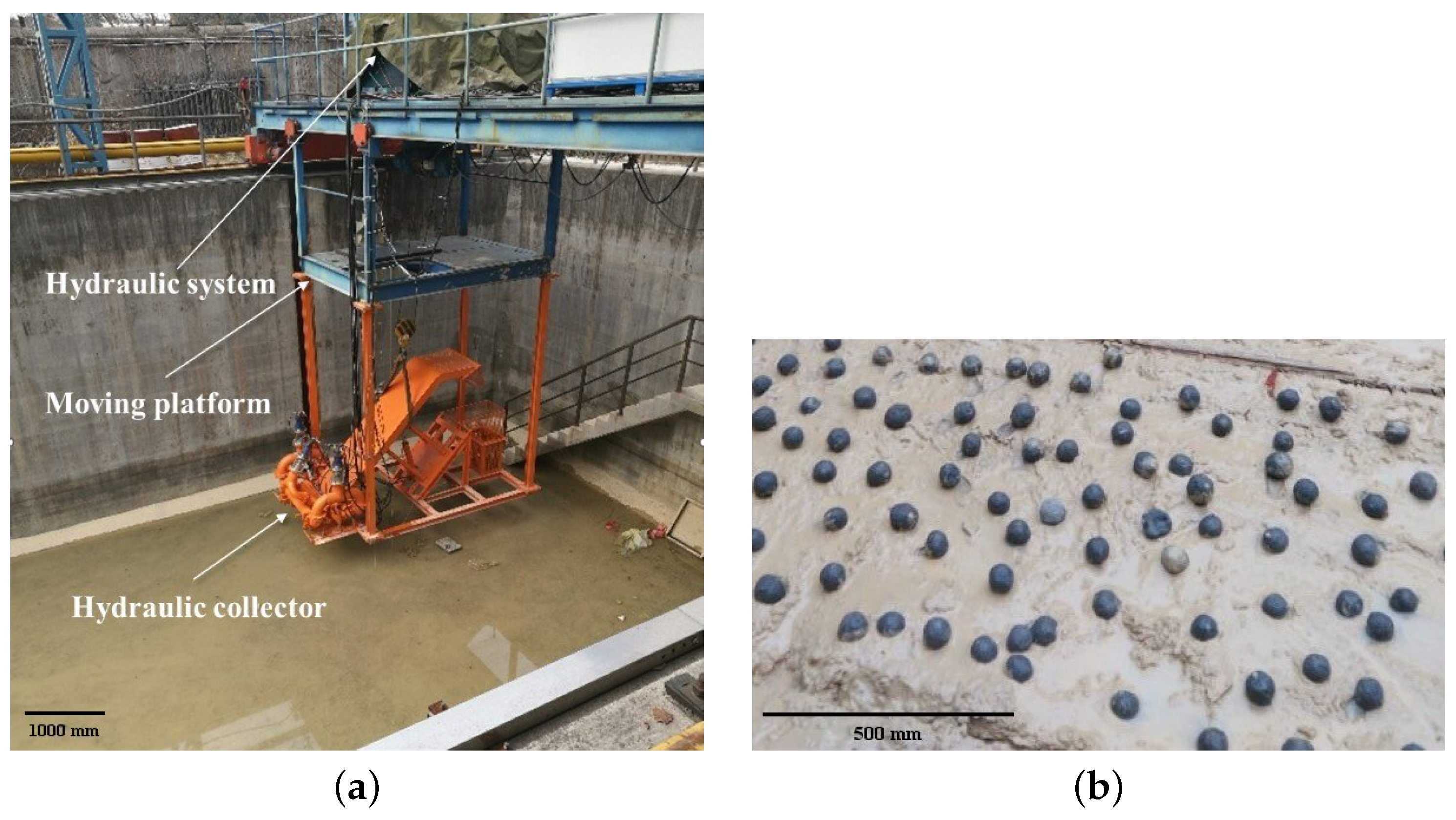
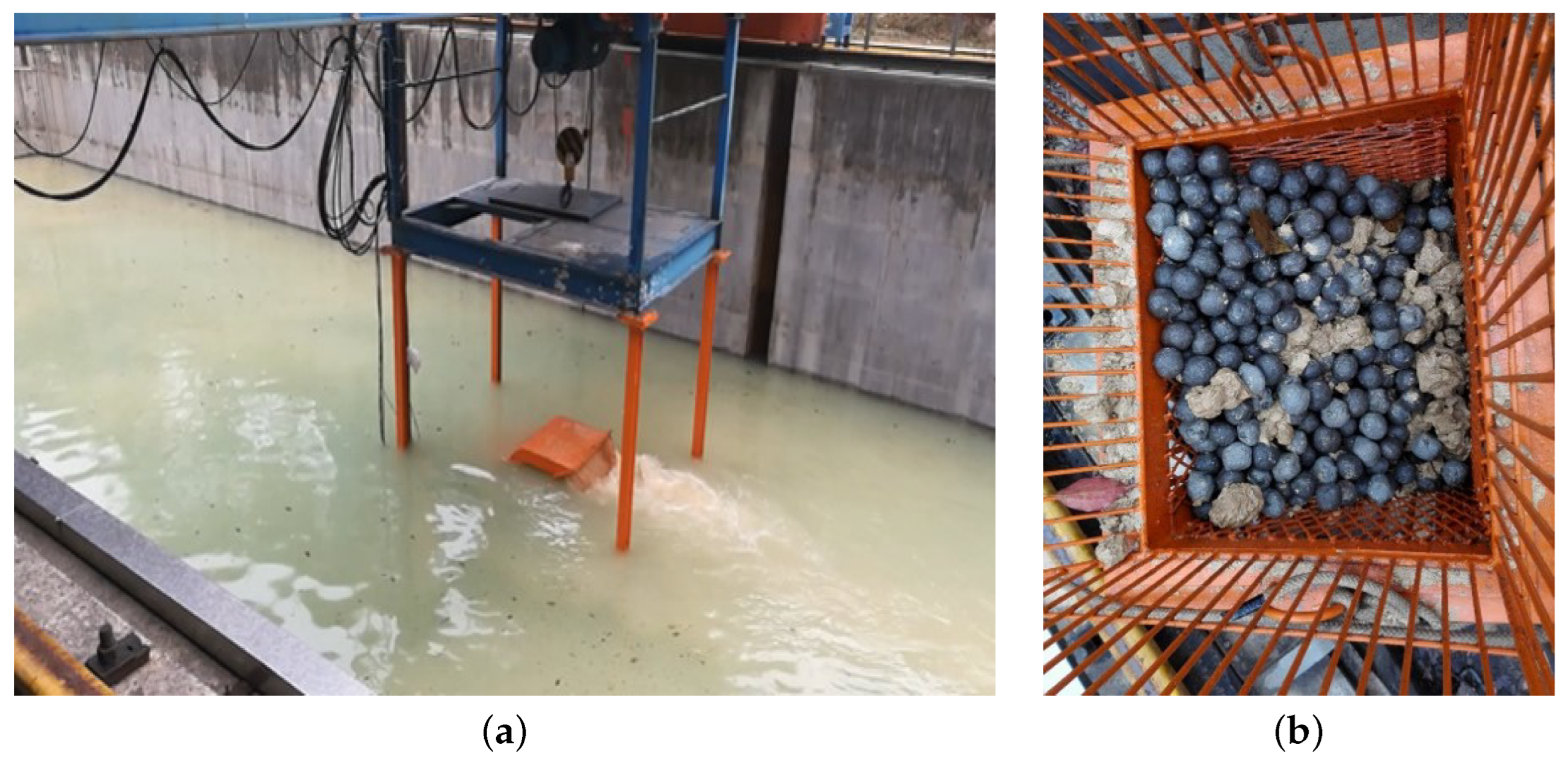
3.3.1. Experimental Setting
3.3.2. Experimental validation
4. Results and Discussions
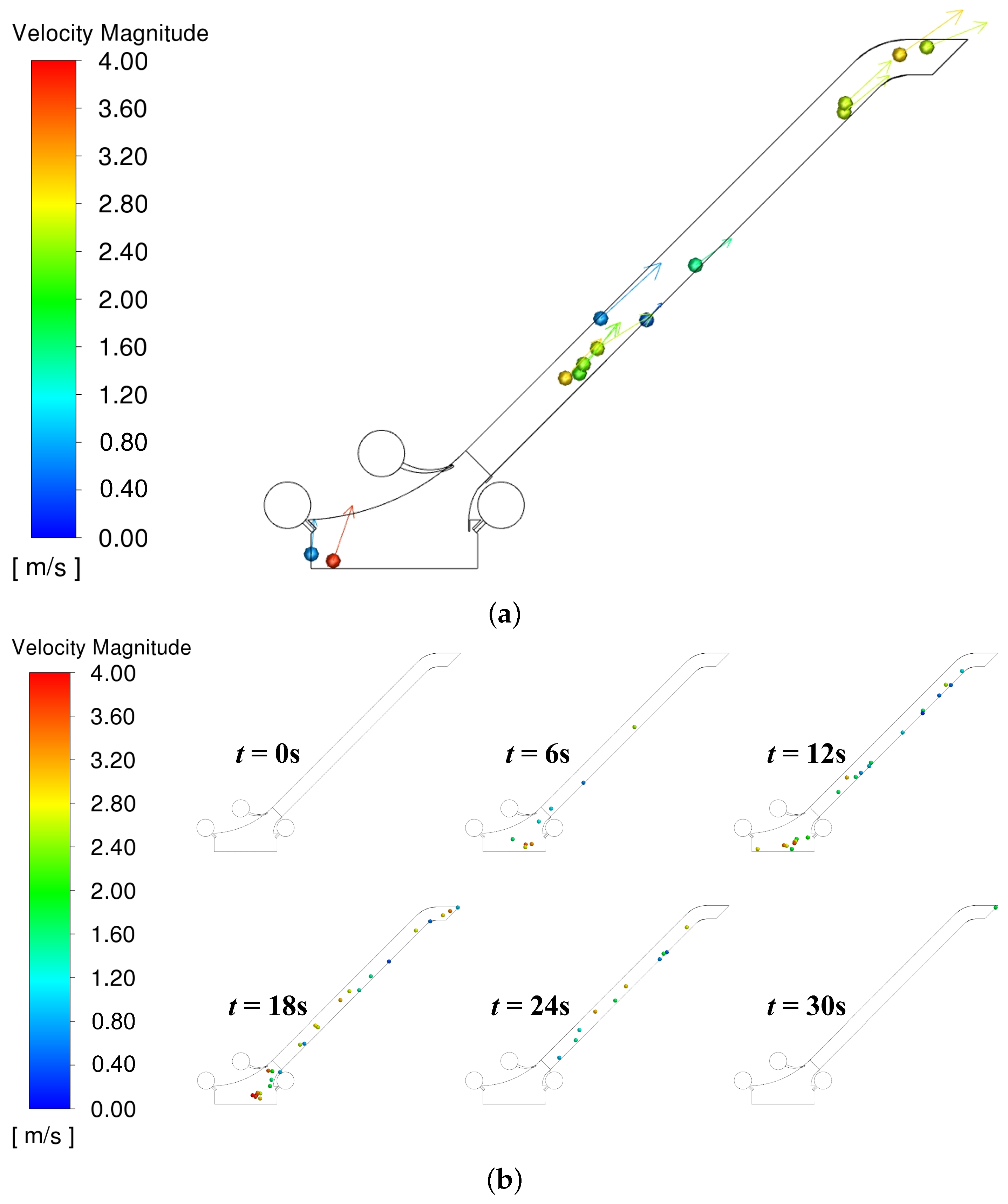
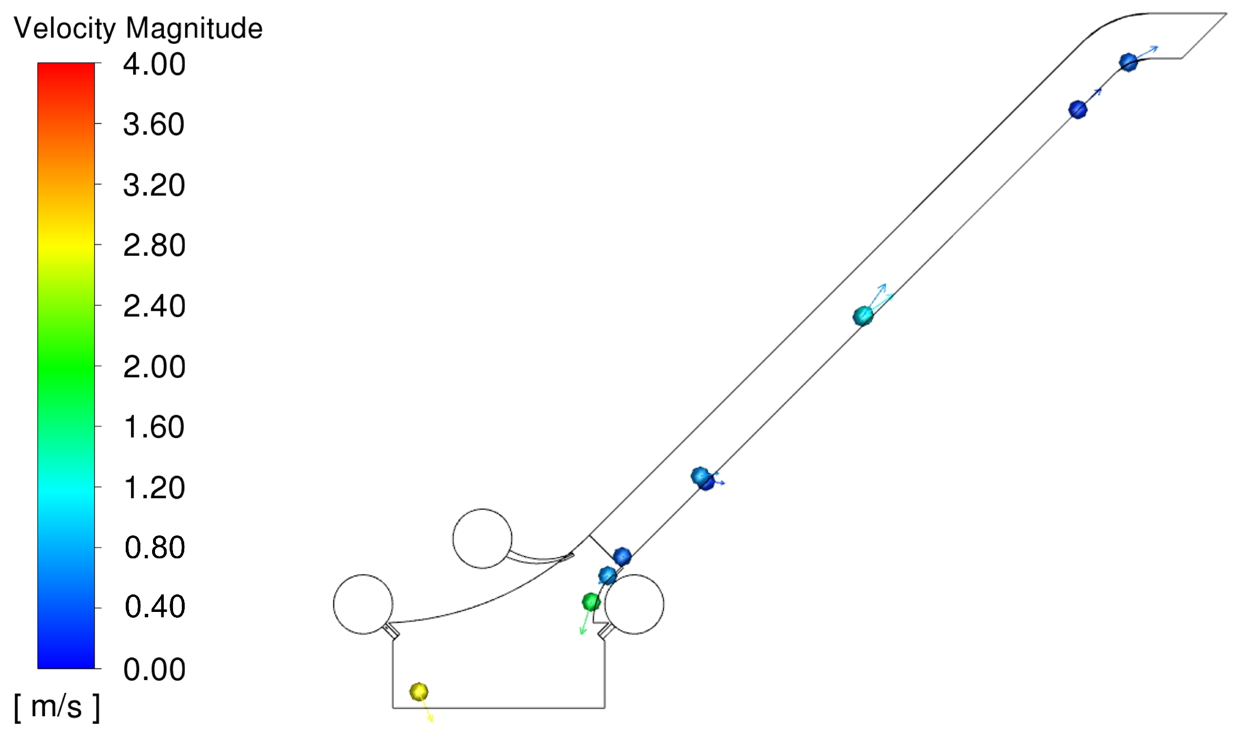
4.1. Distribution of Flow Fields and Polymetallic Nodules
4.2. Influence of Structural Parameters
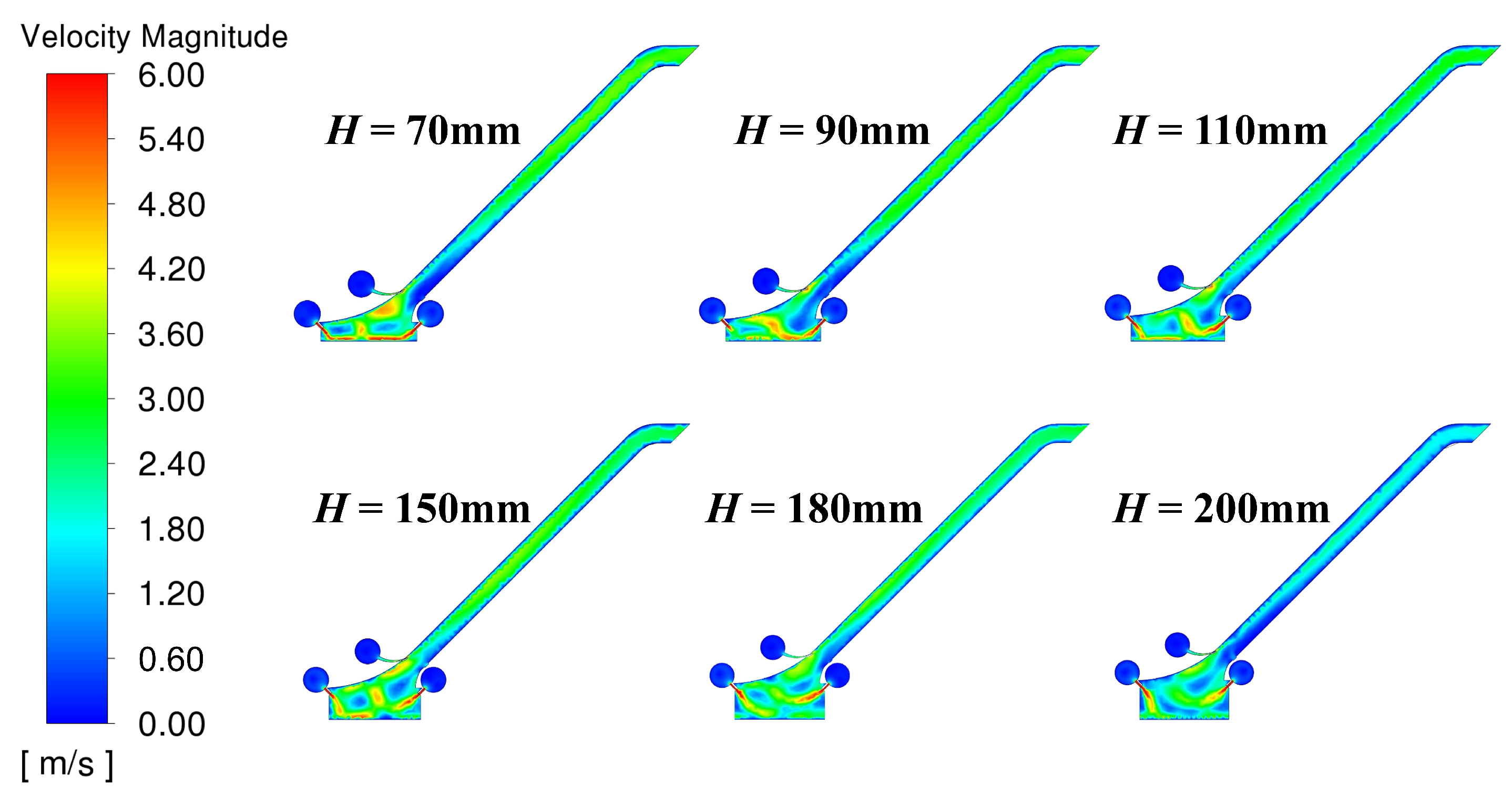
4.2.1. Collection Height
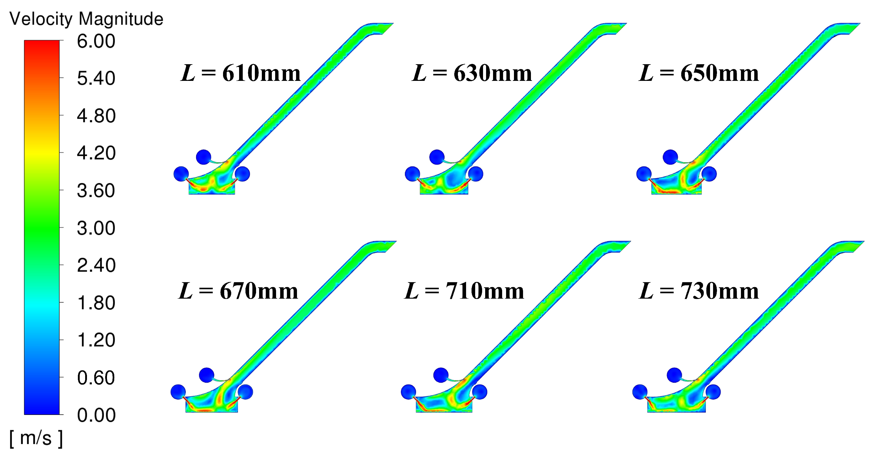
4.2.2. Center Distance between the Front and Rear Acquisition Confluence Tubes
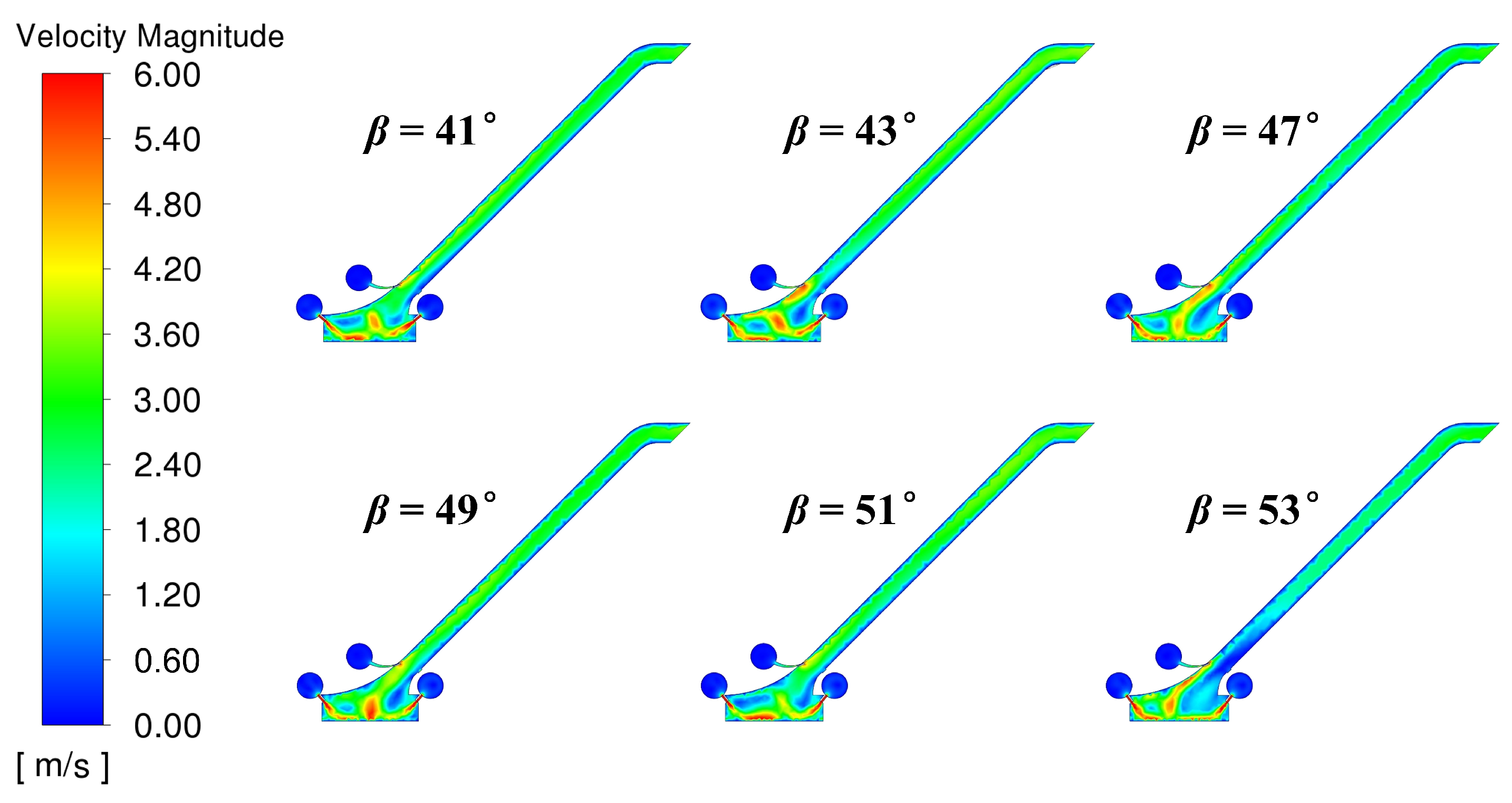
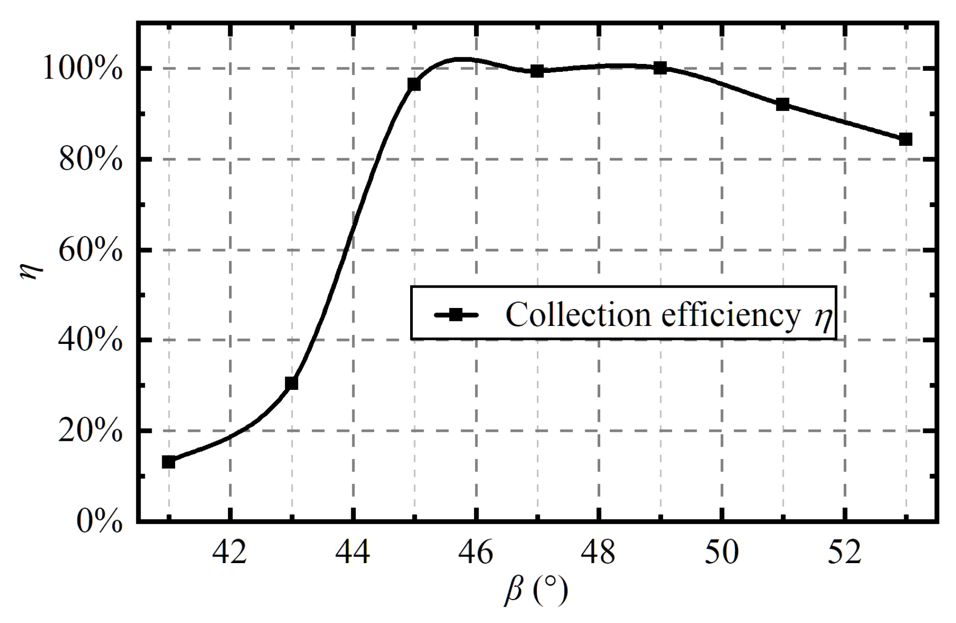
4.2.3. Slant Angle of the Acquisition Nozzle
4.3. Influence of Working Parameters
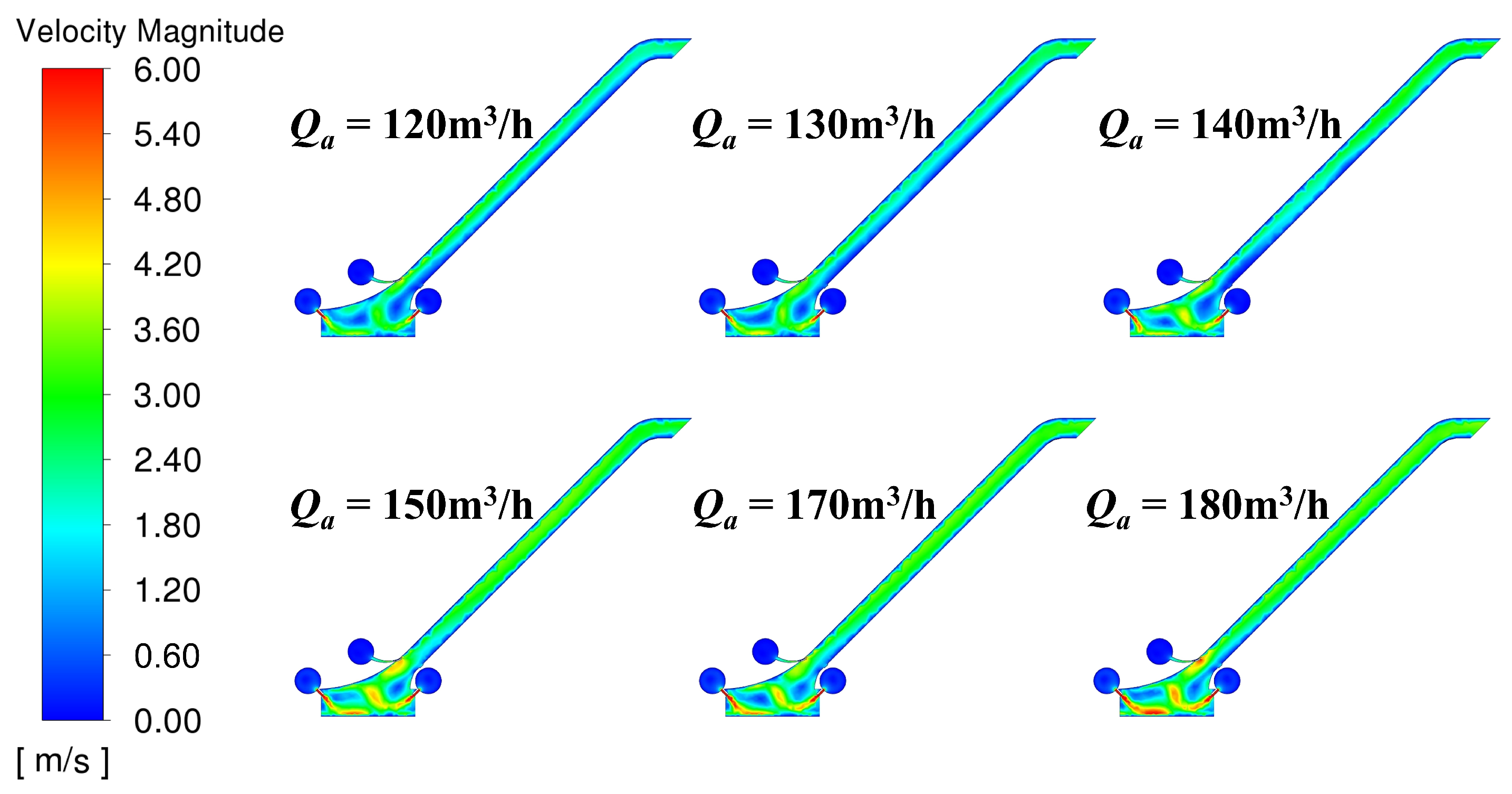
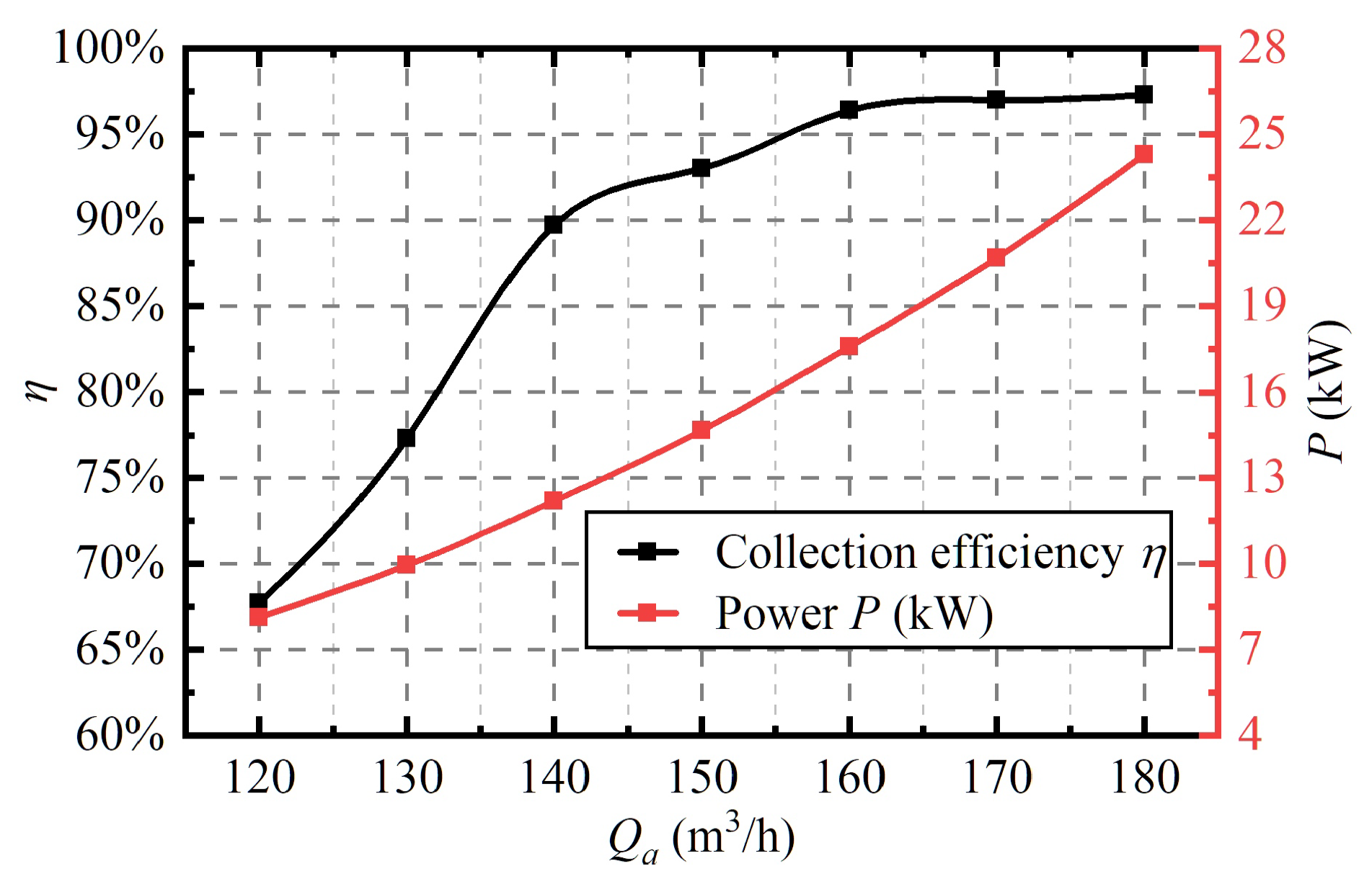
4.3.1. Acquisition Flow Rate
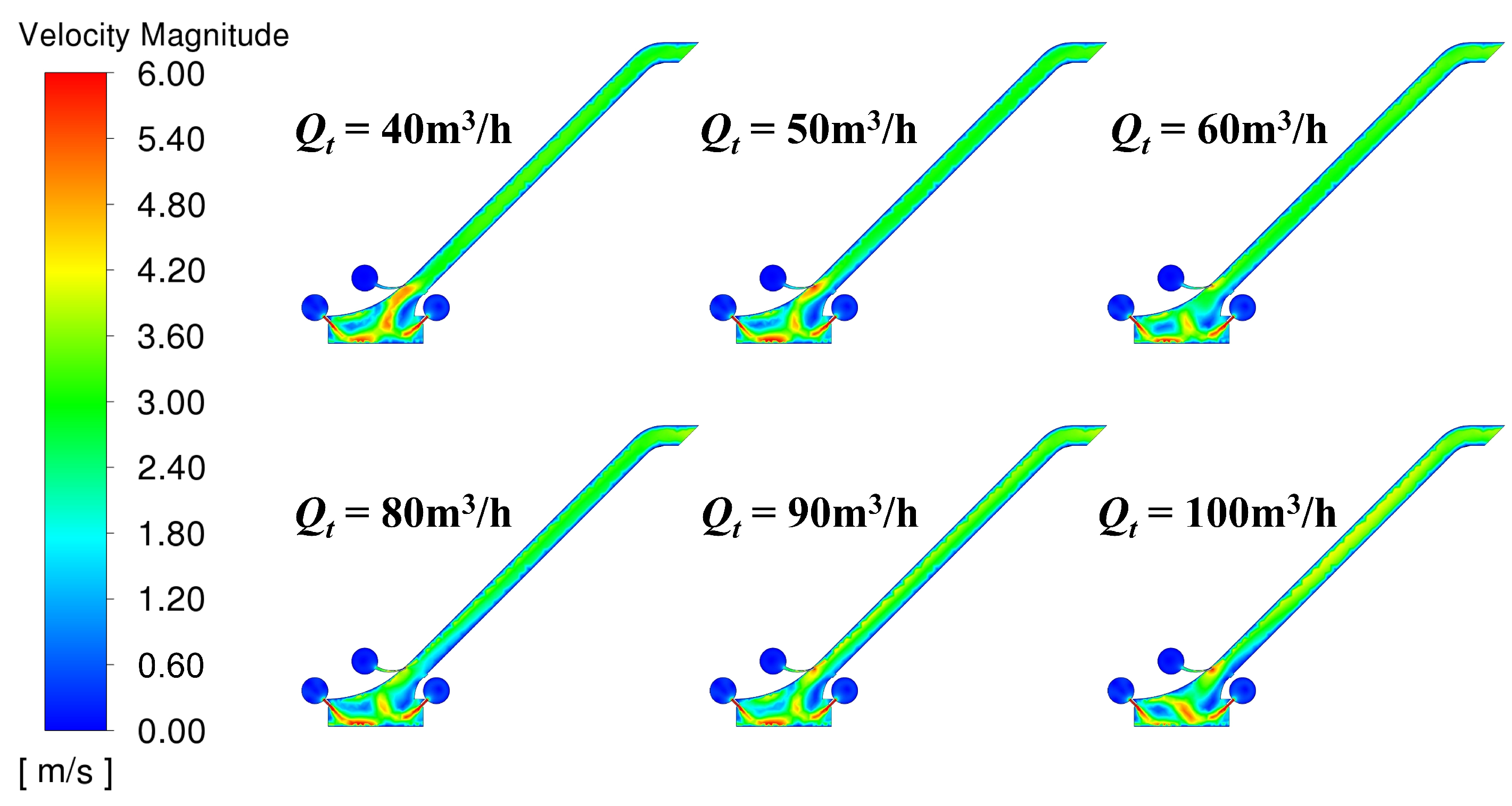
4.3.2. Transmission Flow Rate
4.4. Parameter Importance Analysis
5. Conclusions
Author Contributions
Funding
Institutional Review Board Statement
Informed Consent Statement
Data Availability Statement
Acknowledgments
Conflicts of Interest
References
- Sharma, R. Deep-Sea Mining: Economic, Technical, Technological, and Environmental Considerations for Sustainable Development. Mar. Technol. Soc. J. 2011, 45, 28–41. [Google Scholar] [CrossRef]
- Teague, J.; Allen, M.J.; Scott, T.B. The potential of low-cost ROV for use in deep-sea mineral, ore prospecting and monitoring. Ocean. Eng. 2018, 147, 333–339. [Google Scholar] [CrossRef]
- Hu, Q.; Li, Z.; Zhai, X.; Zheng, H. Development of Hydraulic Lifting System of Deep-Sea Mineral Resources. Minerals 2022, 12, 1319. [Google Scholar] [CrossRef]
- Hein, J.R.; Koschinsky, A.; Kuhn, T. Deep-ocean polymetallic nodules as a resource for critical materials. Nat. Rev. Earth Environ. 2020, 1, 158–169. [Google Scholar] [CrossRef]
- Van Nijen, K.; Van Passel, S.; Squires, D. A stochastic techno-economic assessment of seabed mining of polymetallic nodules in the Clarion Clipperton Fracture Zone. Mar. Policy 2018, 95, 133–141. [Google Scholar] [CrossRef]
- Cheng, Y.; Dai, Y.; Zhang, Y.; Yang, C.; Liu, C. Status and Prospects of the Development of Deep-Sea Polymetallic Nodule-Collecting Technology. Sustainability 2023, 15, 4572. [Google Scholar] [CrossRef]
- Tao, C.; Li, H.; Jin, X.; Zhou, J.; Wu, T.; He, Y.; Deng, X.; Gu, C.; Zhang, G.; Liu, W. Seafloor hydrothermal activity and polymetallic sulfide exploration on the southwest Indian ridge. Chin. Sci. Bull. 2014, 59, 2266–2276. [Google Scholar] [CrossRef]
- Leng, D.; Shao, S.; Xie, Y.; Wang, H.; Liu, G. A brief review of recent progress on deep sea mining vehicle. Ocean. Eng. 2021, 228, 108565. [Google Scholar] [CrossRef]
- Dai, Y.; Zhang, Y.; Li, X. Numerical and experimental investigations on pipeline internal solid–liquid mixed fluid for deep ocean mining. Ocean. Eng. 2021, 220, 108411. [Google Scholar] [CrossRef]
- Sudarvelazhagan, K.; Srinivas, K.; Kumar, M.P.; Ramadass, G.A. Experimental investigation and optimization of polymetallic nodule mining by mechanical pick-up device on deep-sea using RSM. Mar. Georesources Geotechnol. 2023, 41, 254–268. [Google Scholar] [CrossRef]
- Liu, S.; Yang, N.; Han, Q. Research and Development of Deep Sea Mining Technology in China. In Proceedings of the International Conference on Offshore Mechanics and Arctic Engineering, Shanghai, China, 6–11 June 2010; pp. 163–169. [Google Scholar] [CrossRef]
- Wang, P.J.; Li, L.; Wu, J.B. Research on the lightweight structural optimization design of the front collector of the polymetallic nodule miner. Ocean. Eng. 2023, 267, 113275. [Google Scholar] [CrossRef]
- Hong, S.; Choi, J.S.; Kim, J.H.; Yang, C.K. Experimental Study On Hydraulic Performance of Hybrid Pick-up Device of Manganese Nodule Collector. In Proceedings of the Third ISOPE Ocean Mining Symposium, Goa, India, 8–11 November 1999; pp. 69–77. [Google Scholar]
- Yang, N.; Tang, H. Several Considerations of the Design of the Hydraulic Pick-Up Device. In Proceedings of the 5th ISOPE Ocean Mining Symposium, Tsukuba, Japan, 15–19 September 2003; pp. 15–19. [Google Scholar]
- Lim, S.J.; Kim, J.W.; Jung, S.T.; Cho, H.Y.; Lee, S.H. Deep Seawater flow Characteristics Around the Manganese Nodule Collecting Device. Procedia Eng. 2015, 116, 544–551. [Google Scholar] [CrossRef]
- Xiong, H.; Chen, Y.; Yang, N.; Xiao, J.; Li, L. Numerical Study on Settling and Floating Movements of a Sphere Particle Flowing in a Vertical Pipe. In Proceedings of the 28th International Ocean and Polar Engineering Conference, Sapporo, Japan, 10 June 2018; pp. 176–182. [Google Scholar]
- Yue, Z.; Zhao, G.; Xiao, L.; Liu, M. Comparative Study on Collection Performance of Three Nodule Collection Methods in Seawater and Sediment-seawater Mixture. Appl. Ocean. Res. 2021, 110, 102606. [Google Scholar] [CrossRef]
- Zhao, G.; Lu, H.; Xiao, L.; Hu, J. Shape Effect of Polymetallic Nodules on Suction Forces and Flow Field During Seabed Hydraulic Collection. J. Offshore Mech. Arct. Eng. 2021, 144, 011204. [Google Scholar] [CrossRef]
- Yue, Z.; Zhao, G.; Liu, M.; Xiao, L. Experimental and Numerical Methods for Obtaining Flow Field Formed by Hydraulic Nodule Pick-up Devices. Int. J. Offshore Polar Eng. 2021, 31, 378–381. [Google Scholar] [CrossRef]
- Jia, H.; Yang, J.; Su, X.; Xia, Q.; Wu, K. Theoretical Prediction on Hydraulic Lift of a Coandă Effect-Based Mining Collector for Manganese Nodule. Energies 2022, 15, 6345. [Google Scholar] [CrossRef]
- Jia, H.; Yang, J.; Su, X.; Wang, Y.; Wu, K. Flow Characteristics and Hydraulic Lift of Coandă Effect-Based Pick-Up Method for Polymetallic Nodule. Coatings 2023, 13, 271. [Google Scholar] [CrossRef]
- Alhaddad, S.; Helmons, R. Sediment Erosion Generated by a Coandă-Effect-Based Polymetallic-Nodule Collector. J. Mar. Sci. Eng. 2023, 11, 349. [Google Scholar] [CrossRef]
- Alhaddad, S.; Mehta, D.; Helmons, R. Mining of deep-seabed nodules using a Coandă-effect-based collector. Results Eng. 2023, 17, 100852. [Google Scholar] [CrossRef]
- Ren, W.L.; Zhang, X.H.; Zhang, Y.; Lu, X.B. Investigation of motion characteristics of coarse particles in hydraulic collection. Phys. Fluids 2023, 35, 043322. [Google Scholar] [CrossRef]
- Ferziger, J.H.; Perić, M.; Street, R.L. Computational Methods for Fluid Dynamics; Springer: Berlin/Heidelberg, Germany, 2002; Volume 3. [Google Scholar]
- Liu, S.; He, G.; Wang, Z.; Luan, Z.; Zhang, Z.; Wang, W.; Gao, Y. Resistance and flow field of a submarine in a density stratified fluid. Ocean. Eng. 2020, 217, 107934. [Google Scholar] [CrossRef]
- ANSYS. Ansys Fluent Theory Guide, Release 2020R1; ANSYS Inc.: Canonsburg, OA, USA, 2020. [Google Scholar]
- Dai, Y.; Xue, C.; Su, Q.; Huang, X. Numerical analysis on hydrodynamic characteristics of a deep-sea mining vehicle under three typical motions. Ocean. Eng. 2021, 235, 109446. [Google Scholar] [CrossRef]
- Goossens, W.R. Review of the empirical correlations for the drag coefficient of rigid spheres. Powder Technol. 2019, 352, 350–359. [Google Scholar] [CrossRef]
- El Hasadi, Y.M.; Padding, J.T. Do logarithmic terms exist in the drag coefficient of a single sphere at high Reynolds numbers? Chem. Eng. Sci. 2023, 265, 118195. [Google Scholar] [CrossRef]
- Mahieu, B.; Qannari, E.M.; Jaillais, B. Extension and significance testing of Variable Importance in Projection (VIP) indices in Partial Least Squares regression and Principal Components Analysis. Chemom. Intell. Lab. Syst. 2023, 242, 104986. [Google Scholar] [CrossRef]


| Parameter | Definition | Value |
|---|---|---|
| Width of the entrance of the conveying channel | 600 mm | |
| Width of the exit of the conveying channel | 400 mm | |
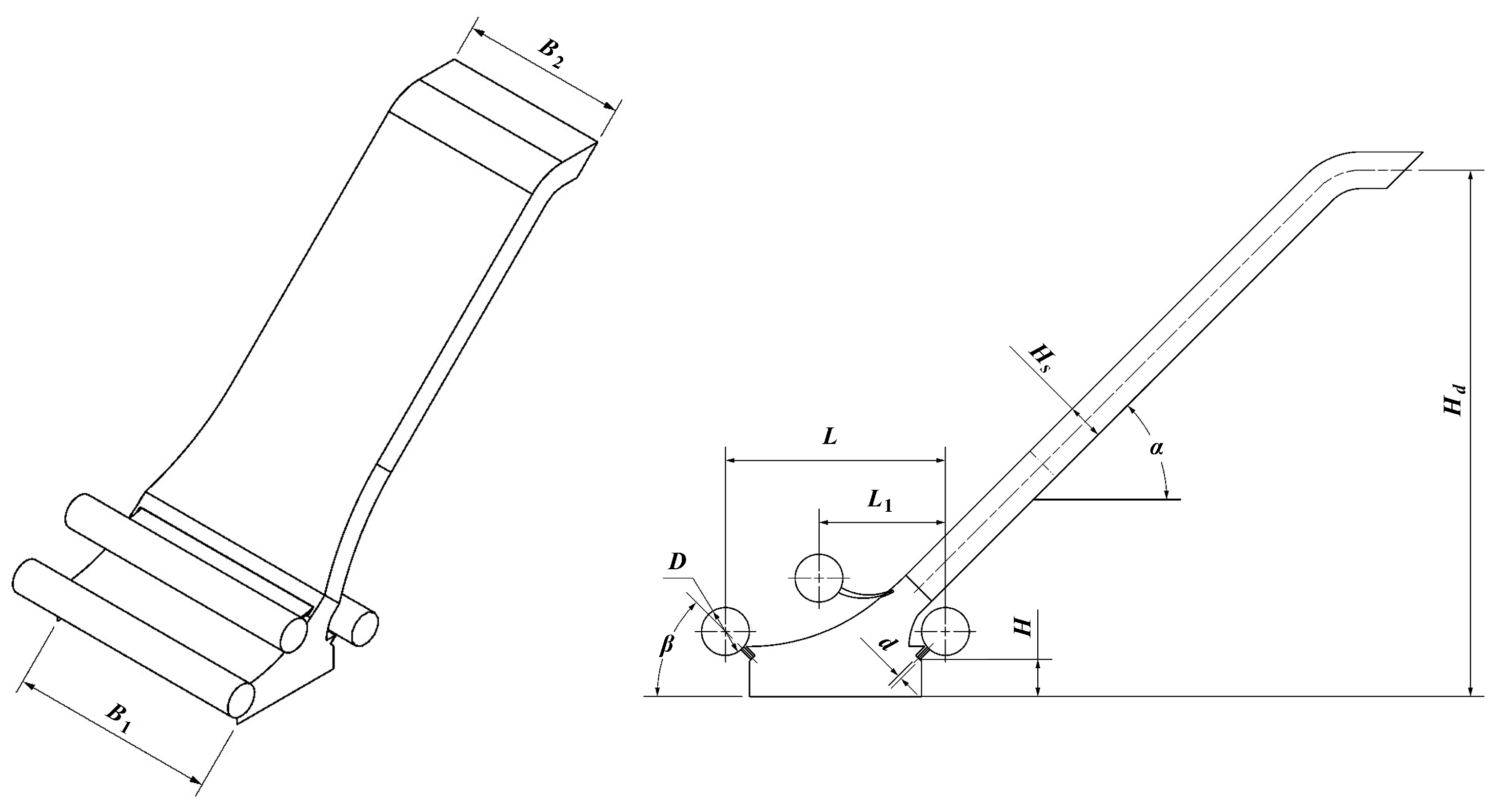
| d | Inner diameter of the acquisition nozzle | 12 mm |
| D | Diameter of the confluence tube | 150 mm |
| H | Collection height | 120 mm |
| Width of the conveying channel | 115 mm | |
| Height of the collector | 1600 mm | |
| Slant angle of the conveying channel | 45 | |
| Slant angle of the acquisition nozzle | 45 | |
| L | Center distance between the front and rear acquisition confluence tubes | 690 mm |
| Horizontal center distance between the transmission and rear acquisition confluence tubes | 390 mm |
| Type | Number of Elements | Collection Efficiency | Error against Very Fine |
|---|---|---|---|
| Coarse | 0.51 | 95.8% | −2.8% |
| Medium | 0.98 | 97.1% | −1.5% |
| Fine | 1.77 | 98.2% | −0.4% |
| Very Fine | 2.52 | 98.6% | - |
| Collection Height H (mm) | Simulated Collection Efficiency | Experimental Collection Efficiency | Error |
|---|---|---|---|
| 70 | 99.3% | 100% | −0.7% |
| 90 | 99.0% | 96.0% | 3.0% |
| 110 | 97.3% | 99.2% | −1.9% |
| 150 | 90.7% | 89.4% | 1.3% |
| 180 | 84.0% | 88.3% | −4.3% |
| 200 | 68.3% | 72.1% | −3.8% |
Disclaimer/Publisher’s Note: The statements, opinions and data contained in all publications are solely those of the individual author(s) and contributor(s) and not of MDPI and/or the editor(s). MDPI and/or the editor(s) disclaim responsibility for any injury to people or property resulting from any ideas, methods, instructions or products referred to in the content. |
© 2023 by the authors. Licensee MDPI, Basel, Switzerland. This article is an open access article distributed under the terms and conditions of the Creative Commons Attribution (CC BY) license (https://creativecommons.org/licenses/by/4.0/).
Share and Cite
Wang, P.-J.; Li, L.; Wei, Q.-N.; Wu, J.-B. Study on Collection Performance of Hydraulic Polymetallic Nodule Collector Based on Solid–Liquid Two-Phase Flow Numerical Simulation. Appl. Sci. 2023, 13, 12729. https://doi.org/10.3390/app132312729
Wang P-J, Li L, Wei Q-N, Wu J-B. Study on Collection Performance of Hydraulic Polymetallic Nodule Collector Based on Solid–Liquid Two-Phase Flow Numerical Simulation. Applied Sciences. 2023; 13(23):12729. https://doi.org/10.3390/app132312729
Chicago/Turabian StyleWang, Pin-Jian, Li Li, Qi-Nan Wei, and Jia-Bin Wu. 2023. "Study on Collection Performance of Hydraulic Polymetallic Nodule Collector Based on Solid–Liquid Two-Phase Flow Numerical Simulation" Applied Sciences 13, no. 23: 12729. https://doi.org/10.3390/app132312729