Abstract
The elastic cushion is mostly used between the layers of ballastless tracks laid on a large-span cable-stayed bridge with a main span of more than 300 m. The rubber material is easy to harden and age, the geotextile has good acid-alkali resistance and antiwear performance, and the feasibility of geotextile application on the large-span cable-stayed bridge can be explored. The coupling model of a long-span cable-stayed bridge and the ballastless track was established to analyze the longitudinal mechanical characteristics of the seamless line, the deformation of the track structure, and the separation of the track plate and base plate under different loads. The results show that the application of geotextile or elastic cushion has little effect on the longitudinal mechanical properties of seamless lines. Compared to the elastic cushion, laying the geotextile increases the longitudinal stress of the slab by 0.13 Mpa, 0.025 Mpa, and 0.06 Mpa under different types of loads. The strength calculation of the seamless track is within the safety range. Laying elastic cushion can restrain the generation of separation under vertical loads, but there is no effect laying elastic cushion under temperature loads and braking loads, and the height of separation was less than 0.4 mm. The stress and deformation of the ballastless track do not exceed the standard when applying geotextile; it is feasible to apply geotextile on ballastless tracks on a large-span cable-stayed bridge. The next step is to study the vehicle–bridge–track dynamic response when elastic cushion and geotextile are laid.
1. Introduction
In recent years, with the rapid development of high-speed railway technology in China, the demand for high-speed railway bridge crossing ability has been improving, especially in crossing rivers, oceans, straits, and valleys, and the cable-stayed bridge with its superior crossing ability has become one of the most common types of long-span bridges in China. Applying ballastless tracks on long-span bridges has two main advantages. First, it can unify the track structure types of the whole line, eliminate the speed limit points of track on the line [1], and meet the basic conditions of a high-speed railway running at 350 km/h or above. The second is to expand the application scope of ballastless tracks on bridges in the world, enrich our country’s ballastless track design theory system, and accumulate the relevant design, construction, and operation experience of applying ballastless tracks on long-span bridges.
At present, there are few engineering cases of ballastless tracks laid on large-span railway cable-stayed bridges [2,3,4]. Although laying ballastless tracks on bridges has its advantages, from the structural characteristics, the large-span cable-stayed bridge has large deformation, and the characteristic of ballastless tracks is high smoothness, which leads to many practical issues during actual operation.
In the research on the deformation characteristics of bridges and tracks, scholars have analyzed the mechanical characteristics of cable-stayed bridges and ballastless tracks under various deformation features. Sheng et al. [5] introduced the structural characteristics of the Ganjiang Bridge and adopted some structural measures to improve the feasibility of applying tracks on long-span cable-stayed bridges. Zhu et al. [6] took a 300 m cable-stayed bridge with a main span as an example to analyze the deformation adaptability of the track and the long-span cable-stayed bridge. Han et al. [7] investigated some typical statics and dynamics problems under the actual conditions of a long-span cable-stayed high-speed railway bridge with a main span of 400 m and laying ballastless track. Zheng et al. [8] studied the influence of the long-span cable-stayed bridge on track structures under the most unfavorable antibending deformation. Sheng et al. [9] studied the effect of the local deformation mode of the cable-stayed bridge on the track. Zheng et al. [10] established a sectional model in the laboratory to obtain the maximum bend deformation conditions of a long-span cable-stayed bridge and studied the deformation characteristics of the track. Sheng et al. [11] designed and established a segment model of a long-span cable-stayed bridge, analyzed the cross-sectional arrangement of suspension cable points and the discontinuous arrangement of tracks on the cross-sectional arrangement of suspension cable points, and conducted fatigue tests and postfatigue loading tests. Qin et al. [12] presented the in situ testing and the finite element model updating (FEMU) of the Ganjiang Bridge, China’s first long-span ballastless railway cable-stayed bridge with a main span that reaches up to 300 m before its opening for operation. Wang et al. [13] aimed to investigate the distribution of the temperature field, the time variability of temperatures, and the representative value of temperature actions in stayed cables. To improve the adaptability of the track and the long-span cable-stayed bridge, an elastic cushion is introduced to the track on the bridge. According to the existing research, it is advantageous to apply elastic cushion on the track on the bridge. Li [14] showed that elastic cushion can effectively coordinate the interlayer deformation of the track structure and significantly reduce the dynamic response of the base. Xie et al. [15] pointed out that the fatigue life of the slab can be effectively improved by increasing the stiffness of the elastic cushion. Qin [16] pointed out that under temperature load, geotextile between layers of the track structure on the cable-stayed bridge is more disadvantageous than the setting of elastic cushion, and the phenomenon of interlayer splitting and emptying occurs in some areas. Sheng et al. [17] conducted a full-scale fatigue test on CRTS III slab track on a long-span bridge and found that the track would not crack when the elastic vibration isolation layer was laid.
In the research on seamless track on cable-stayed bridges, Cai et al. [18] established the finite element model of a long-span cable-stayed bridge, and the research shows that installing REJ on a long-span cable-stayed bridge can significantly reduce the longitudinal force of rail. Zhao et al. [19] established a spatial finite element model for a 1092 m main span suspension bridge based on the bridge–track interaction theory and put forward a specific correction method to keep the rail in a zero-stress state when just laid. Yan et al. [20] described the evolution process of the track–bridge interaction model from the simplest elastic bar and linear longitudinal resistance model to the complex beam–rail interaction model considering the loading history.
In the research on the dynamic response of ballastless tracks on bridges, Guo et al. [21] studied the dynamic performance of tracks on long-span cable-stayed bridges under different train loads. Wang et al. [22] presented a random dynamic analysis of a high-speed train moving over a long-span cable-stayed bridge. Lu and Li [23] aimed to investigate the longitudinal vibration and vibration reduction in a cable-stayed bridge under vehicular loads with an emphasis on longitudinal resonance. Fan et al. [24] established a finite element model (FEM) according to the design documents of a long-span rail-cum-road cable-stayed bridge and analyzed the dynamic response of the cable under the train loads based on the FEM and numerical model.
In summary, in China, the engineering practice of laying ballastless tracks on large-span cable-stayed bridges is relatively scarce. Within the limited engineering context, scholars have obtained research findings in areas such as statistics and dynamics through their professional expertise. Ballastless tracks on bridges often use the CRTS Ⅲ slab track or CRTS Ⅰ double-block ballastless track. To improve the adaptability between the bridge and the ballastless track structure, the geotextile isolation layer is replaced with an elastic cushion layer when laying the ballastless track on the cable-stayed bridge with a main span of more than 300 m. However, based on site laying experience, the rubber elastic cushion will age under the influence of the external environment [25]. Laying elastic cushions on track on long-span cable-stayed bridges may face maintenance problems and incur huge economic costs. The geotextile has good acid, alkali resistance, and wear resistance [26], and it is also low-cost and easy to construct. The first challenge we face is whether cable-stayed bridges with a main span of over 300 m can use a geotextile isolation layer. At present, there is no engineering example of a ballastless track laying geotextile on a large-span cable-stayed bridge over 300 m. This is also the difference between the research background of this paper and other papers. Secondly, as the main span of cable-stayed bridges becomes increasingly larger, the sensitivity of the bridge ballastless track structure to external loads also changes. It cannot be judged based on previous research. It is necessary to establish a refined finite element model according to the engineering context. This paper takes the Dongping large-span cable-stayed bridge of the Guangzhou-ZhanJiang Railway with a main span of 350 m as the background first analyzes the influence of geotextile and elastic cushion, respectively, on the longitudinal mechanical characteristics of jointless tracks on the bridge and the stress and deformation of track structure and compares the gap between the layers of track structure under vertical load, braking load, and temperature load, and explores feasibility of applying geotextile on track on the long-span cable-stayed bridge. The expected research results hold significant engineering and practical value for guiding the installation of ballastless track systems on bridges.
2. Engineering Background
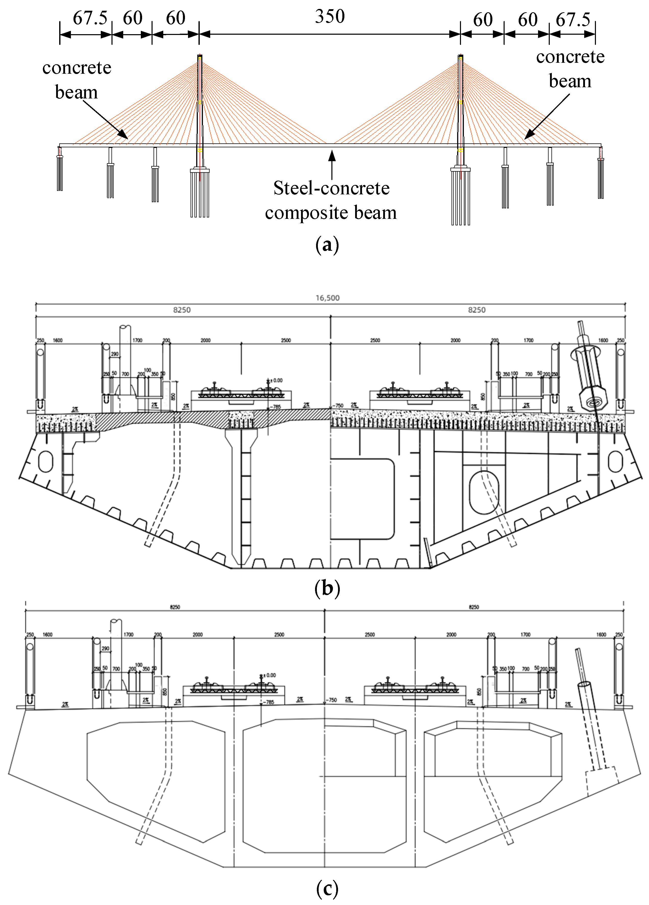
The engineering background of this paper is based on the Guangzhou-Zhanjiang Railway Dongping waterway cable-stayed bridge. The bridge span arrangement is (67.5 + 60 + 60 + 350 + 60 + 60 + 67.5) meters, with a distance of 0.9 m from the beam end to the center of the beam end support; the total bridge length is 726.8 m. The main bridge is a double-tower, seven-span cable-stayed bridge with two auxiliary piers in the side spans. The effective height of the tower above the bridge deck Is 109 m. The bridge employs a hybrid girder design, with 209.4 m of concrete box girder at each end and a combined girder for the middle section, featuring a steel–concrete combined segment at the joint. The structure of the bridge is illustrated in the Figure 1 below. The Dongping cable-stayed bridge utilizes a semi-floating structure system, meaning the tower and pier are consolidated, but the tower and beam are separated. Longitudinal movable bearings and dampers are set on top of the piers to constrain the longitudinal displacement of the bridge. The design speed is 350 km/h, and it is currently the domestically, and even the world’s, longest main span with the highest design speed of the long-span cable-stayed bridge that lays ballastless track.
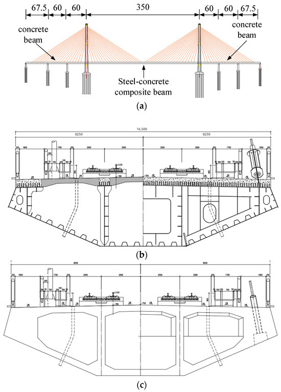
Figure 1.
Dongping long-span cable-stayed bridge (unit:m): (a) overall structure diagram; (b) steel–concrete composite beam cross-section; (c) concrete beam cross-section.
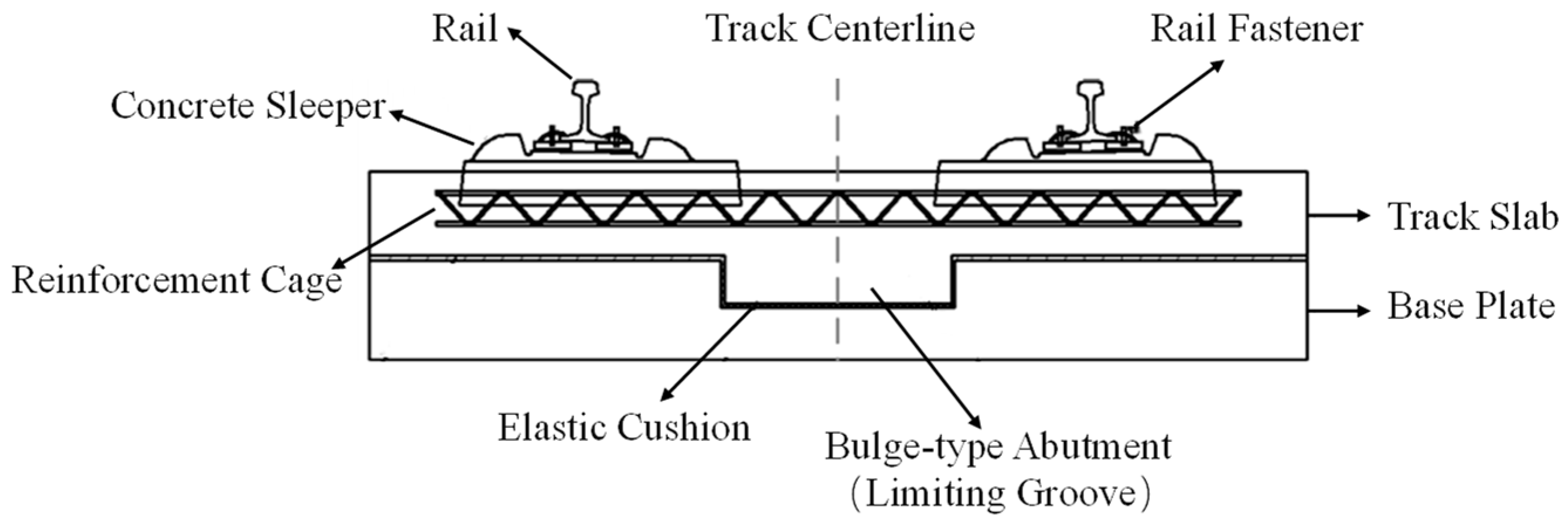
A CRTS I-type double-block ballastless track is laid on the cable-stayed bridge, consisting of steel rails, a WJ-8B-type fastening system, prefabricated double-block sleepers, concrete track slabs, geotextile isolation layers, and concrete base plates. The standard track slabs on the bridge are 5920 mm long, 280 mm wide, and 260 mm thick. An 80 mm gap is set between adjacent track slabs, as specifically illustrated in Figure 2.

Figure 2.
CRTS I-Type Double-Block Ballastless Track.
3. Finite Element Modeling
3.1. Model of Cable-Stayed Bridge-Ballastless Track
In this paper, based on the Guangzhou-Zhanzhan Railway, the finite element model of a ballastless track-long span cable-stayed bridge is established. The dimensions of the bridge and track structure are consistent with reality. The model is divided into a cable-stayed bridge model and a CRTS I-type slab track model. The cable-stayed bridge model includes the main beam, tower, stay cables, piers, and bridge bearings. The main beam uses solid element C3D8R, following the actual dimensions, and different material properties are assigned to different structures to distinguish between concrete beams and steel beams, ensuring the total mass of the cable-stayed bridge is consistent with reality. As the focus is not on the tower, to improve calculation speed, the tower uses beam elements with a box-section type, and the stayed cables use truss elements, which only bear tensile forces and not compressive forces. The piers and bridge bearings are simplified as spring elements, setting the bridge’s vertical, longitudinal, and transverse stiffness. Tie connections are used between the tower and stayed cables and the stayed cables and the main beam. No constraints are set at both ends of the main beam, maintaining consistency with the actual situation.
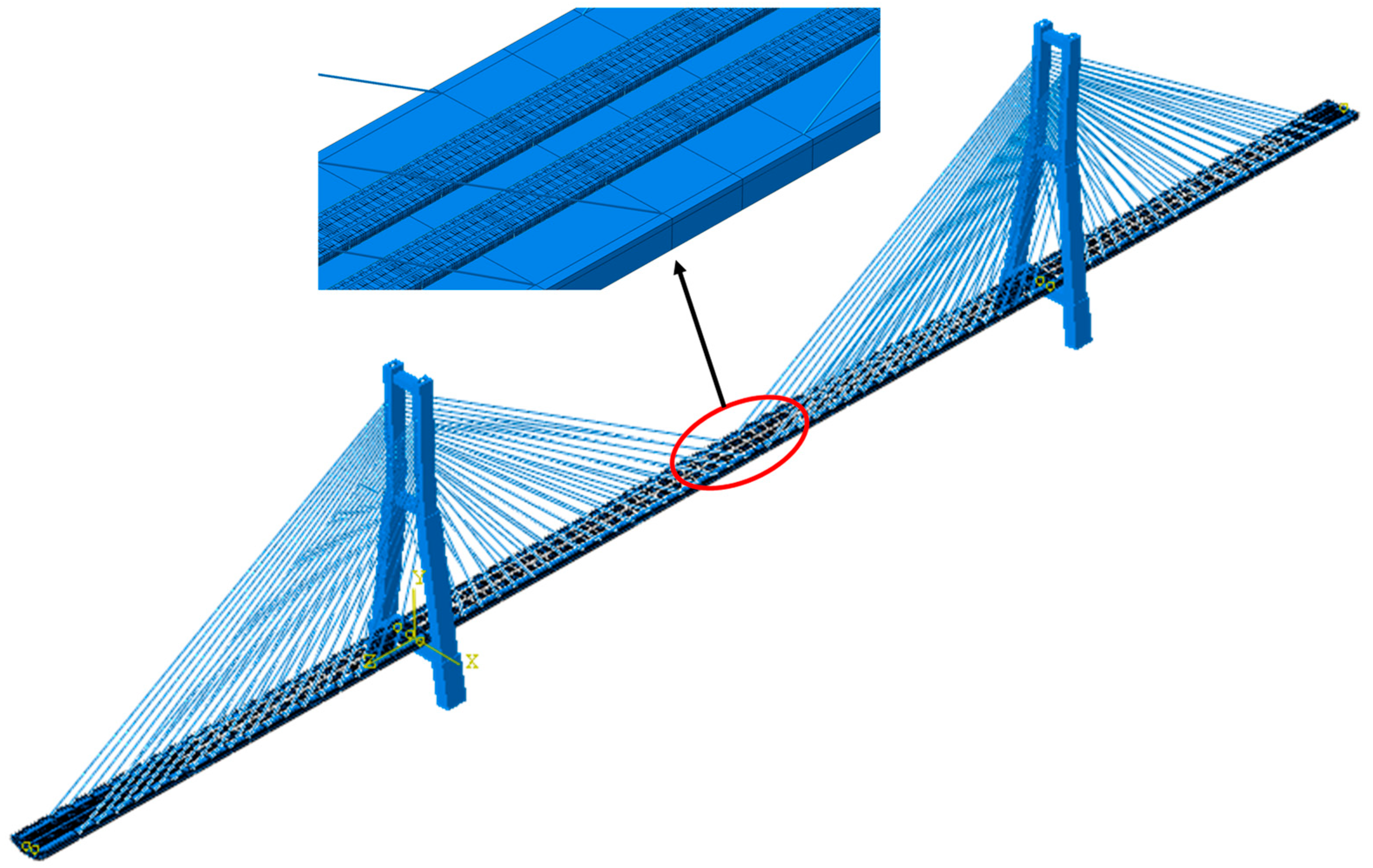
The ballastless track uses CRTS I-type slab track, taking into consideration all the track components. Steel rails use beam elements to improve computational efficiency; the fasteners use low-resistance clips with longitudinal nonlinear springs. Track slabs and base plates use C3D8R solid elements with contact simulation to model the interlayer relationship. The methods for simulating the geotextile and elastic cushion layers will be introduced later. The base plate is cast in situ on the bridge, so a tie connection is used between the two. The finite element model is shown in Figure 3.
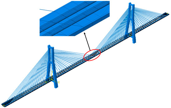
Figure 3.
Cable-Stayed Bridge Ballastless Track Finite Element Model.
3.2. Material Parameters
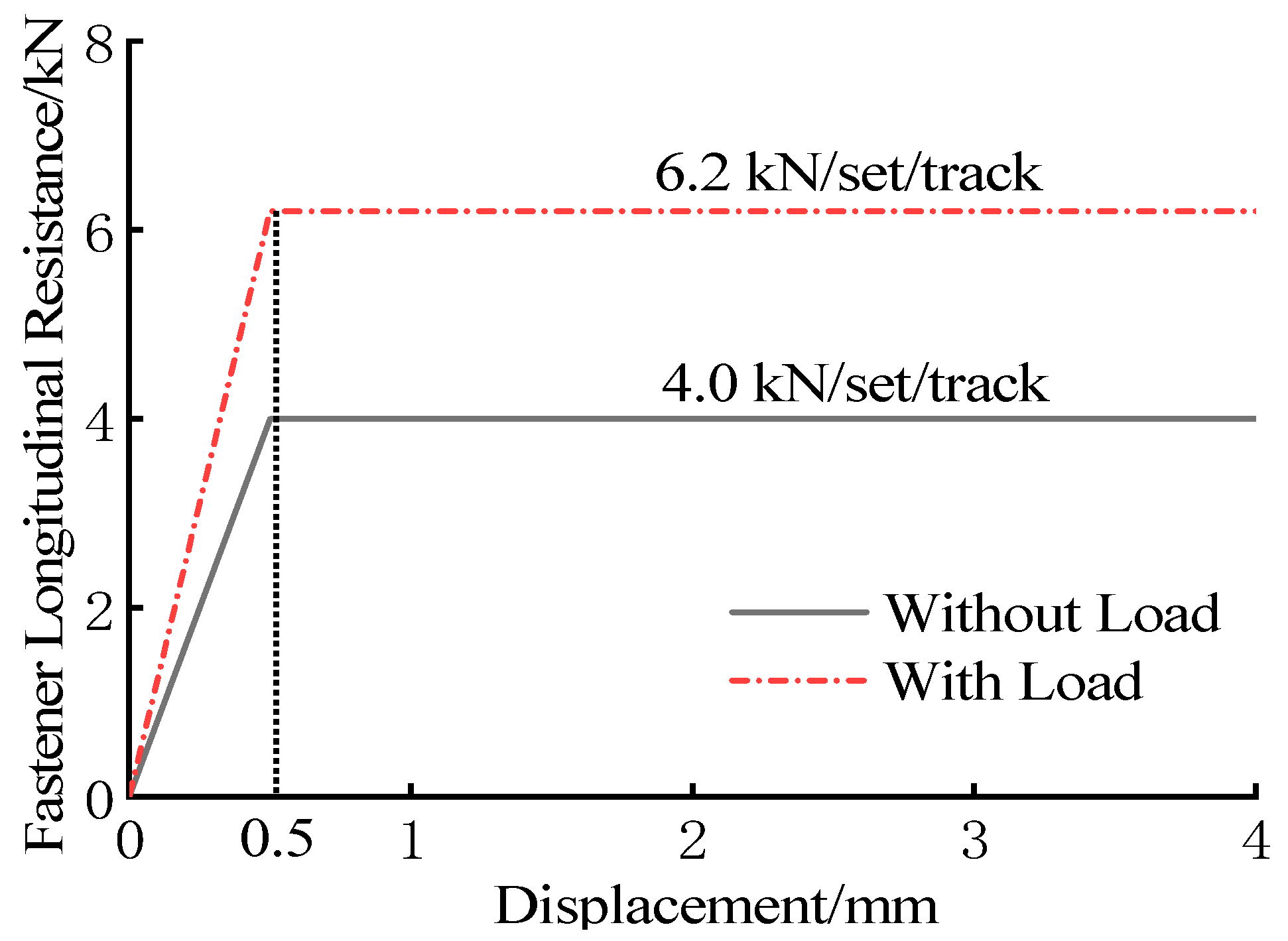
Rail density is 7800 kg/m3, elastic modulus 2.1 × 10⁵ MPa, and Poisson ratio 0.3. The longitudinal resistance–displacement relationship [6] is shown in Figure 4. The lateral and vertical use linear springs, and fastener stiffness values are 50 kN/mm and 35 kN/mm, respectively. The precast sleeper is made of C60 concrete, the cast-in-place concrete slab is made of C40 concrete, and the base slab is made of C40 concrete. C55 concrete is used for the cable tower, C55 concrete is used for the box beam of the main rail beam and steel beam, and C55 concrete is also used for the combined beam bridge panel. The elastic modulus of the cable is 2 × 10⁵ Mpa.

Figure 4.
WJ-8-type fastener longitudinal resistance–displacement curve (low-resistance).
3.3. Simulation of Geotextile and Elastic Cushion
To accurately analyze the influence of geotextile and elastic cushion on the track of a long-span cable-stayed bridge, it is very important to simulate the geotextile and elastic cushion of the track structure on the bridge. In this paper, interlayer contact is used to simulate the geotextile. According to the reference [6], the friction coefficient of tangential behavior is 0.7, and the normal behavior is simulated by “hard contact”, which is consistent with the actual situation. The elastic cushion is also simulated by interlayer contact. Since the longitudinal and transverse limit of the track plate is mainly realized through the convex baffle, it is difficult to slide in the longitudinal direction, and the friction coefficient of the elastic cushion has not been studied at present. The tangential behavior can be simulated with a larger friction coefficient. In this paper, 0.7 is adopted. The normal behavior is simulated with linear contact stiffness, and the static stiffness of the elastic cushion is not clearly defined. Refer to the specification “High-speed Railway CRTS III type plate Ballastless track rubber elastic cushion layer” to take 20 kN/mm.
3.4. Model Verification
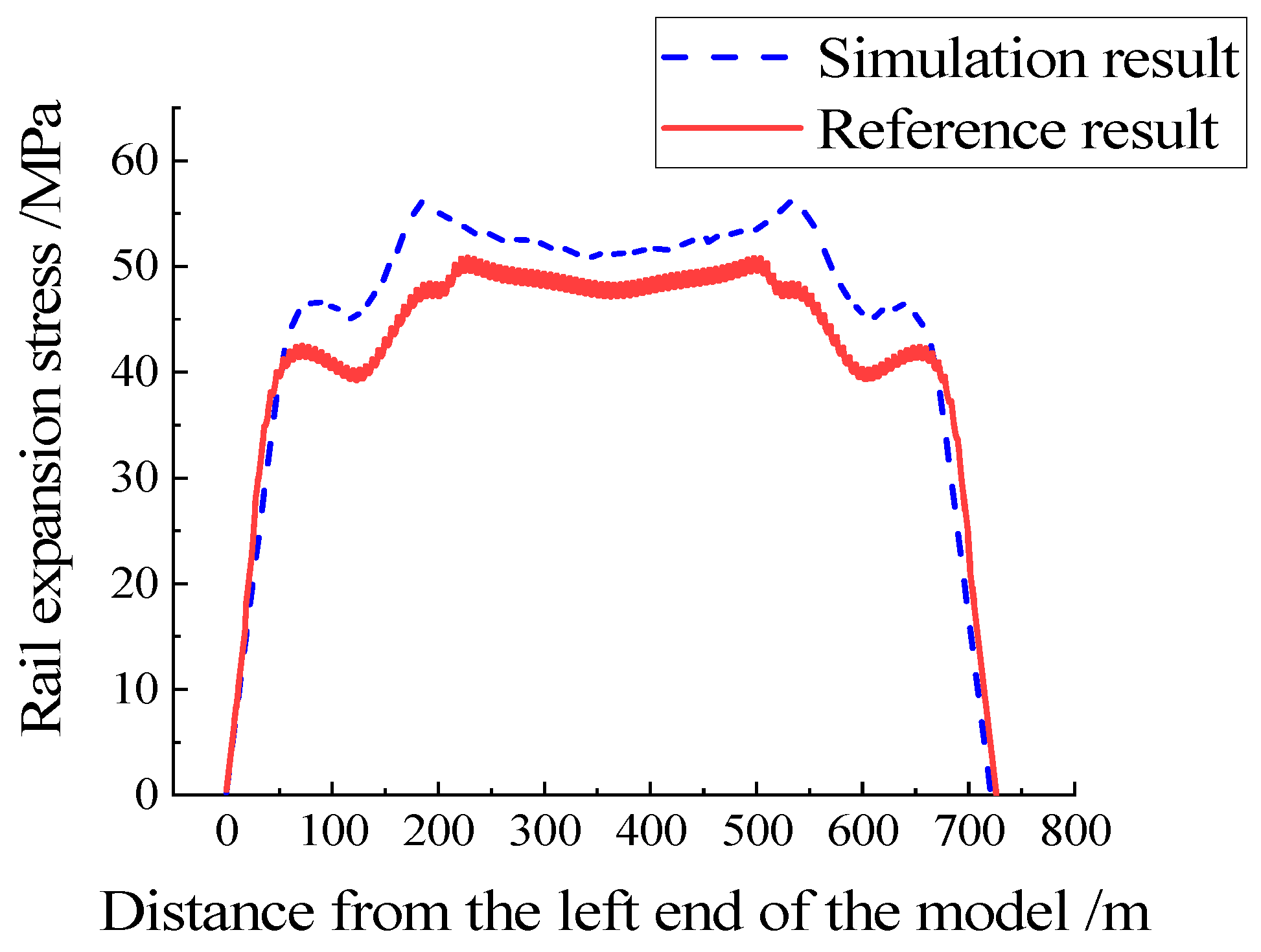
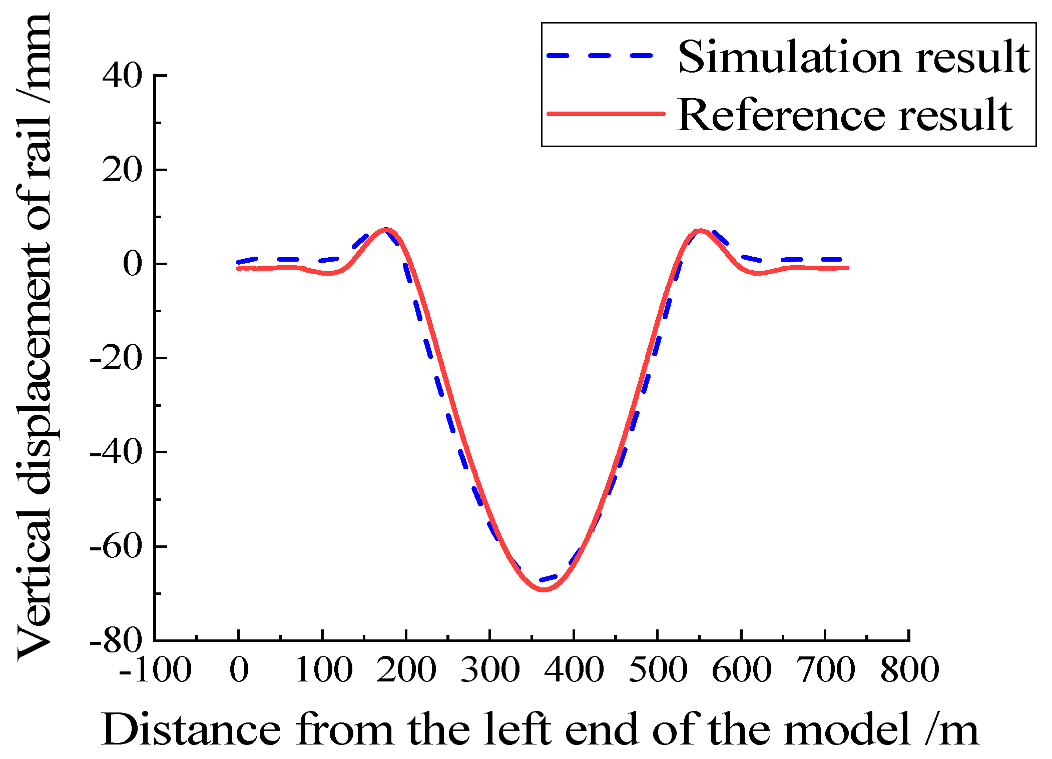
In this paper, the rail expansion stress and vertical deformation when laying Geotextile on the track on the bridge are compared with the research report, as shown in Figure 5 and Figure 6. From the figure, it can be seen that the finite element model established in this article is consistent with the longitudinal stress and vertical deformation laws of the seamless track in the research report provided by China Railway Design Corporation.
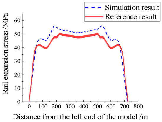
Figure 5.
Rail expansion stress.
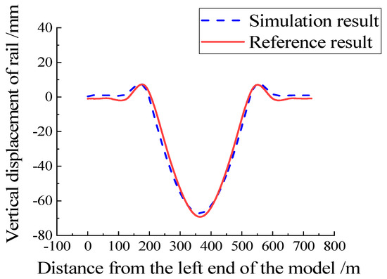
Figure 6.
Rail vertical displacement.
4. Influence of Geotextile and Elastic Cushion on Seamless Line on the Bridge
Vertical load, braking load, and temperature load, respectively, correspond to three typical longitudinal forces in seamless lines: flexural force, braking force, and expansion force. The influences of geotextile and elastic cushion on longitudinal mechanical deformation characteristics of seamless lines are, respectively, considered under three different load types.
4.1. Vertical Load
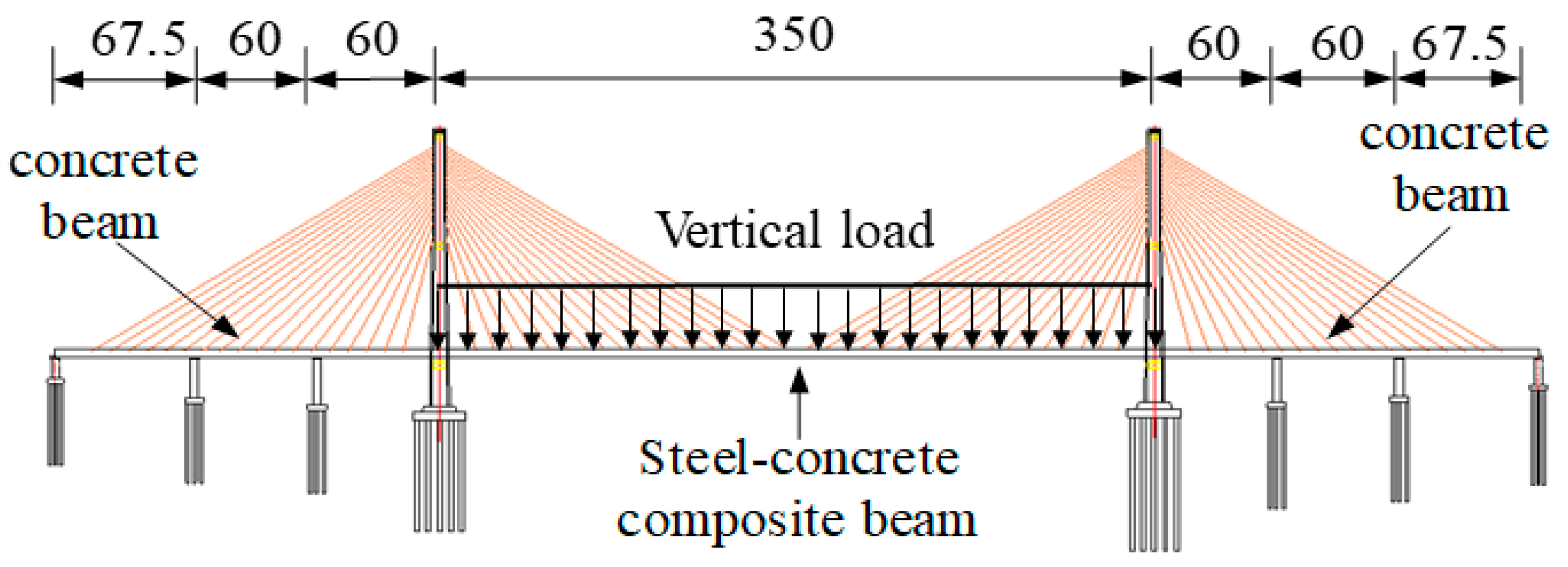
The vertical load adopts the ZK load of a high-speed railway, simplifies the vertical load of the train to the uniform load of 64 kN/m/line, adopts the most unfavorable loading mode, that is, the midspan load of a cable-stayed bridge, and the loading length is 350 m. as shown in Figure 7.
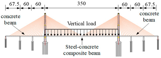
Figure 7.
Vertical load.
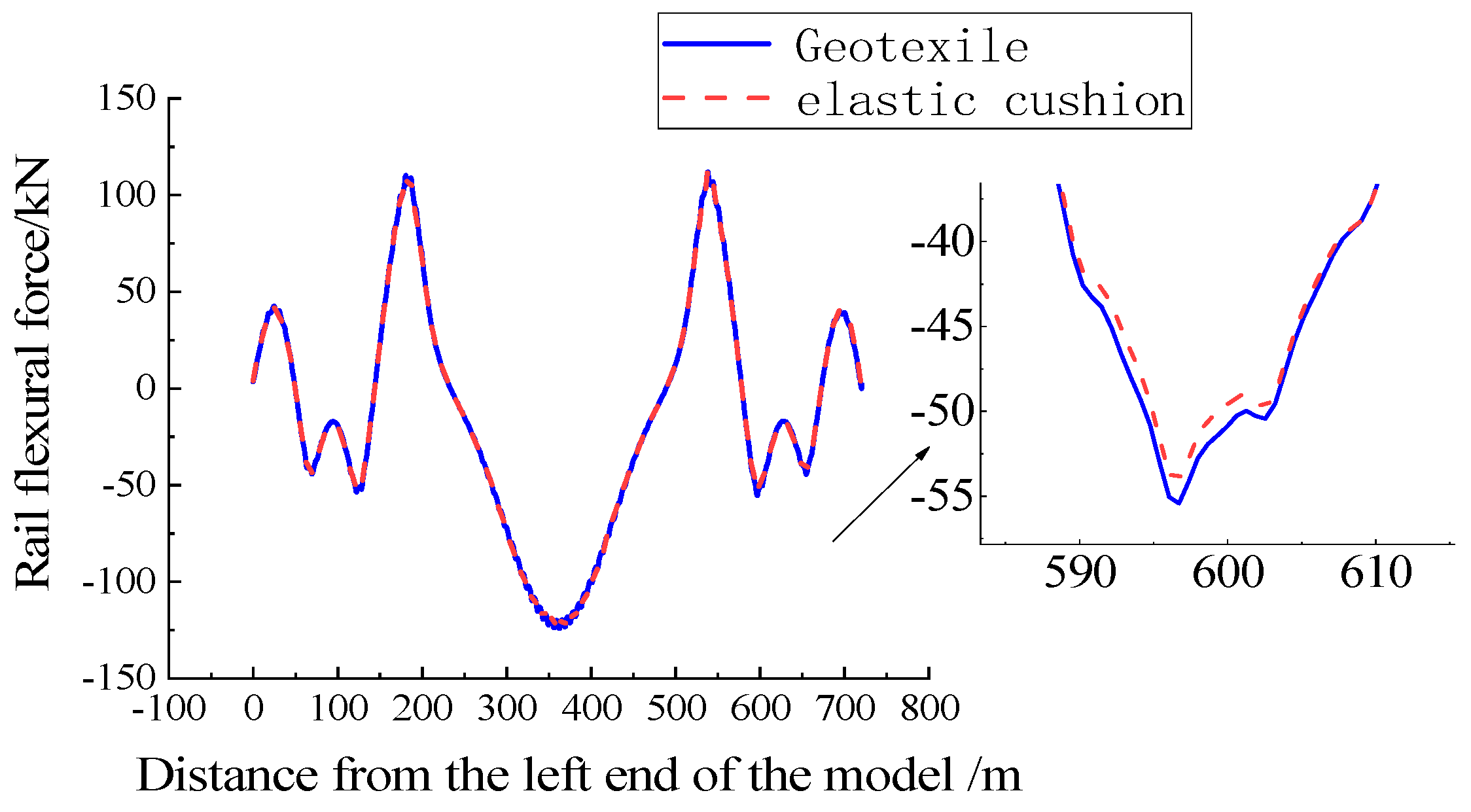
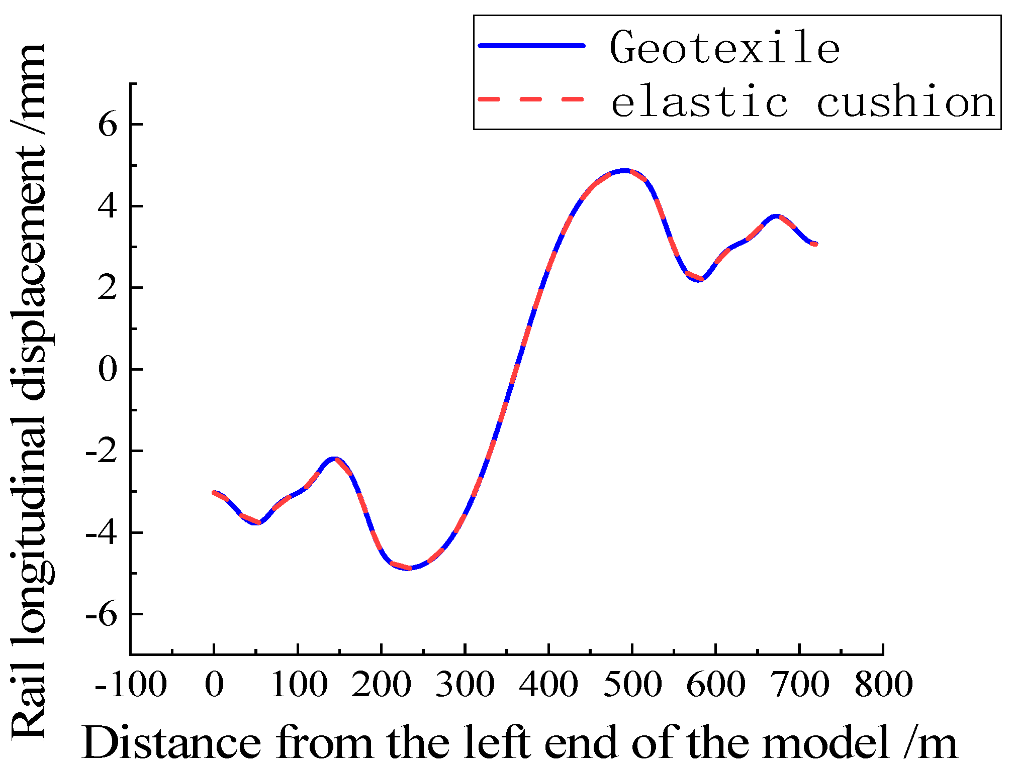
As shown in Figure 8, under vertical load, when an elastic cushion is laid, the flexural pressure of the rail in the span is 124.5 kN, and the flexural tension of the rail near the bridge tower is 110.5 kN. When the geotextile is laid, the flexural pressure of the rail in the span is 124.1 kN, and the flexural tension of the rail near the bridge tower is 110.1 kN. On the cable-stayed bridge, the laying of geotextile or elastic cushion on the ballastless track does not affect the distribution of rail flexural force. The rail flexural pressure reaches the maximum in the span of the main beam, and the maximum flexural tension is located near the bridge tower. As shown in Figure 9, the geotextile or elastic cushion laid on the track under vertical load does not affect the longitudinal displacement distribution law of the rail, and the position where the maximum longitudinal displacement of the rail occurs does not change significantly. The geotextile and elastic cushion correspond to the maximum longitudinal displacement in the rail of 4.88 mm and 4.87 mm, respectively.

Figure 8.
Rail force under vertical load.
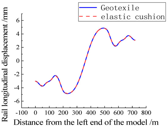
Figure 9.
Rail longitudinal displacement under vertical load.
4.2. Braking Load
Braking force is calculated according to Equation (1)
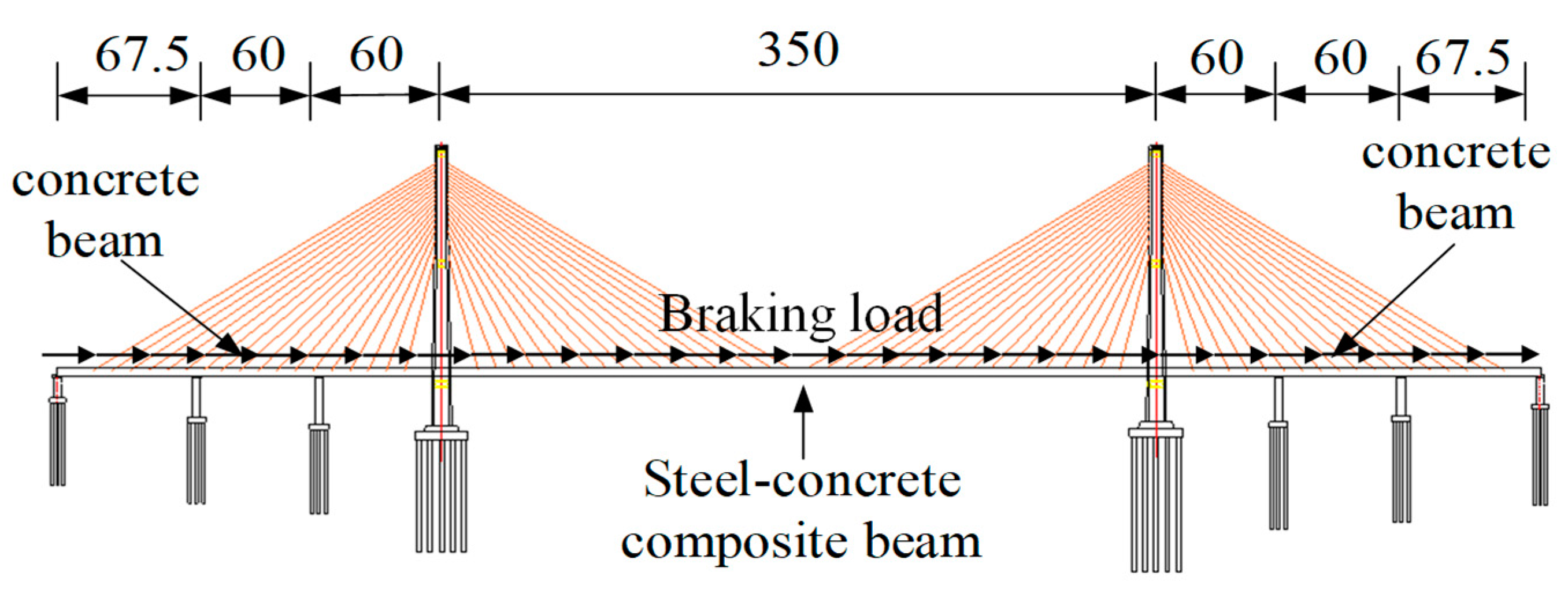
In Equation (1), μ is the braking rate 0.164, and Qq for the design live load takes ZK standard live load 10.5 kN/m/ line using the most unfavorable loading mode, that is, full-bridge dual-line braking, as shown in Figure 10.
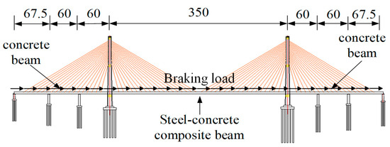
Figure 10.
Braking load.
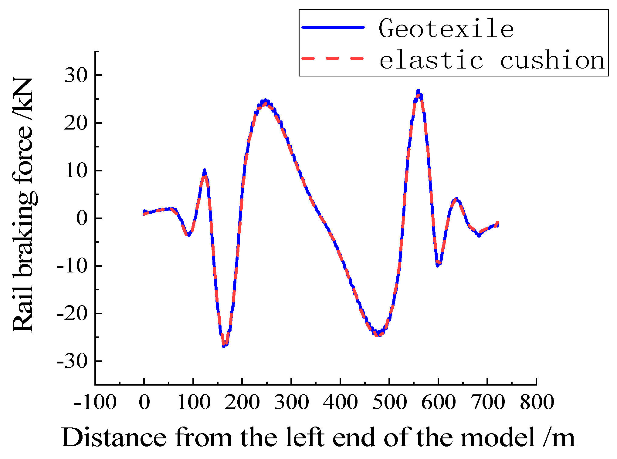
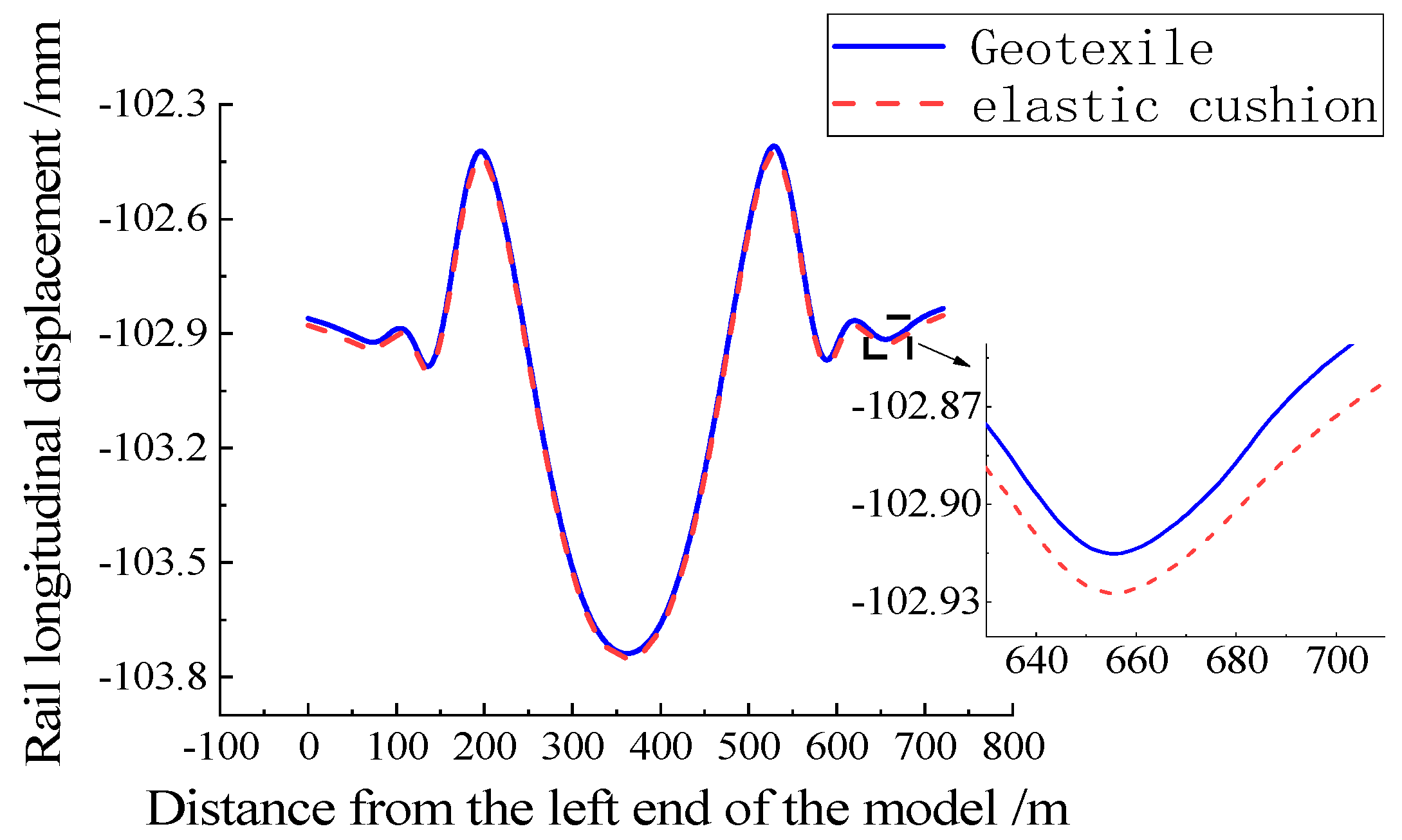
It can be seen from Figure 11 that the law of rail braking force is consistent when a geofabric or elastic cushion is laid on the ballastless track on the bridge. The peak abrupt position of the rail braking force is located near the bridge tower, the amplitude is 51.8 kN, and the maximum longitudinal displacement of the rail occurs at the midspan position, as shown in Figure 12. When an elastic cushion is laid on the ballastless track on the bridge, the longitudinal displacement of the rail is 102.88 mm, which is slightly larger than the longitudinal displacement of the rail under geotextile laying 102.86 mm, and the difference is negligible.

Figure 11.
Rail force under braking load.
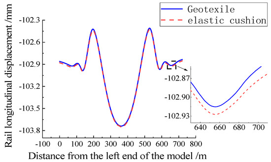
Figure 12.
Rail longitudinal displacement under braking load.
4.3. Temperature Load
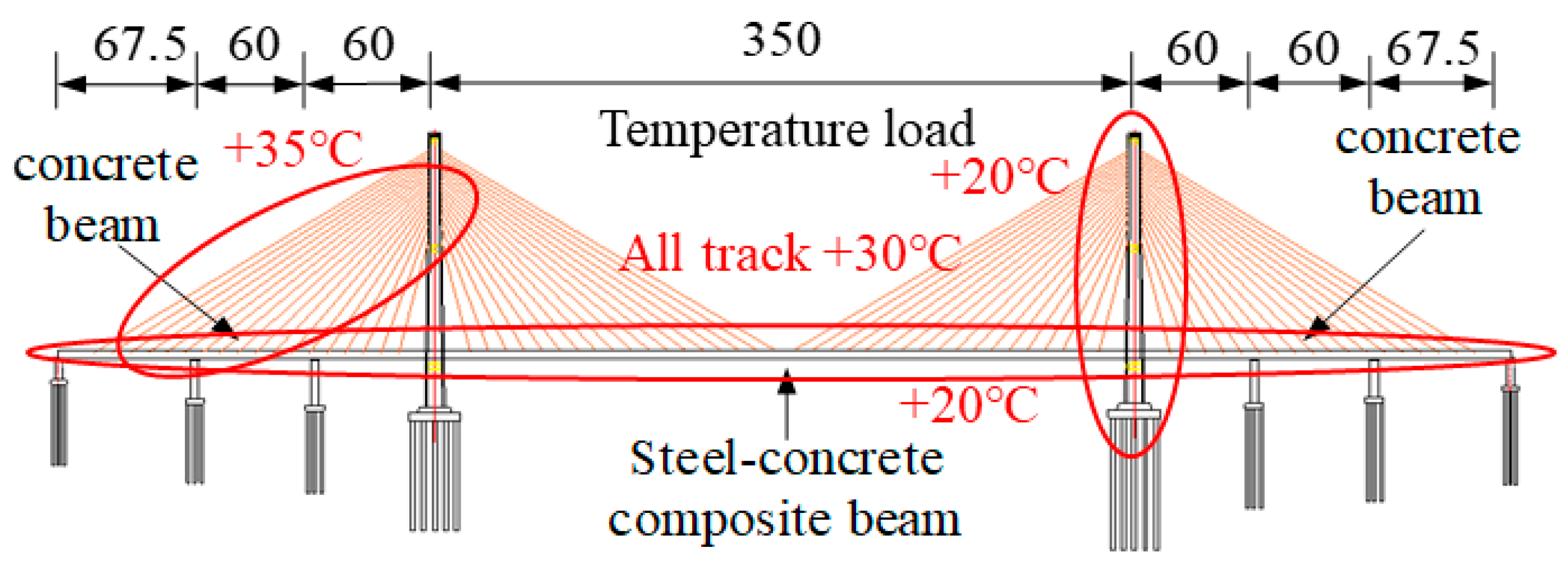
According to the Code for Design on Railway Cable-stayed Bridge (TB10095-2020, China) [27], the temperature difference of cable-stayed bridge members has a great influence on seamless lines, so the temperature load on the bridge adopts the temperature difference of members. The temperature rise in the main beam is 20 °C, the temperature rise in the tower is 20 °C, and the temperature rise in the stayed cable is 35 °C. Considering the shielding effect of the track structure, the temperature of the track structure should be higher than that of the main beam, so the temperature rise of the track plate and the base plate should be 30 °C, as shown in Figure 13.
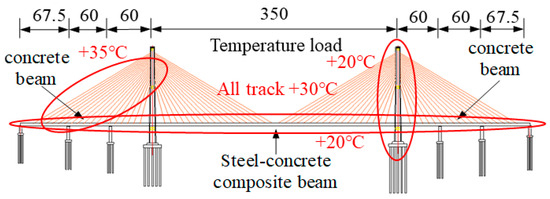
Figure 13.
Temperature load.
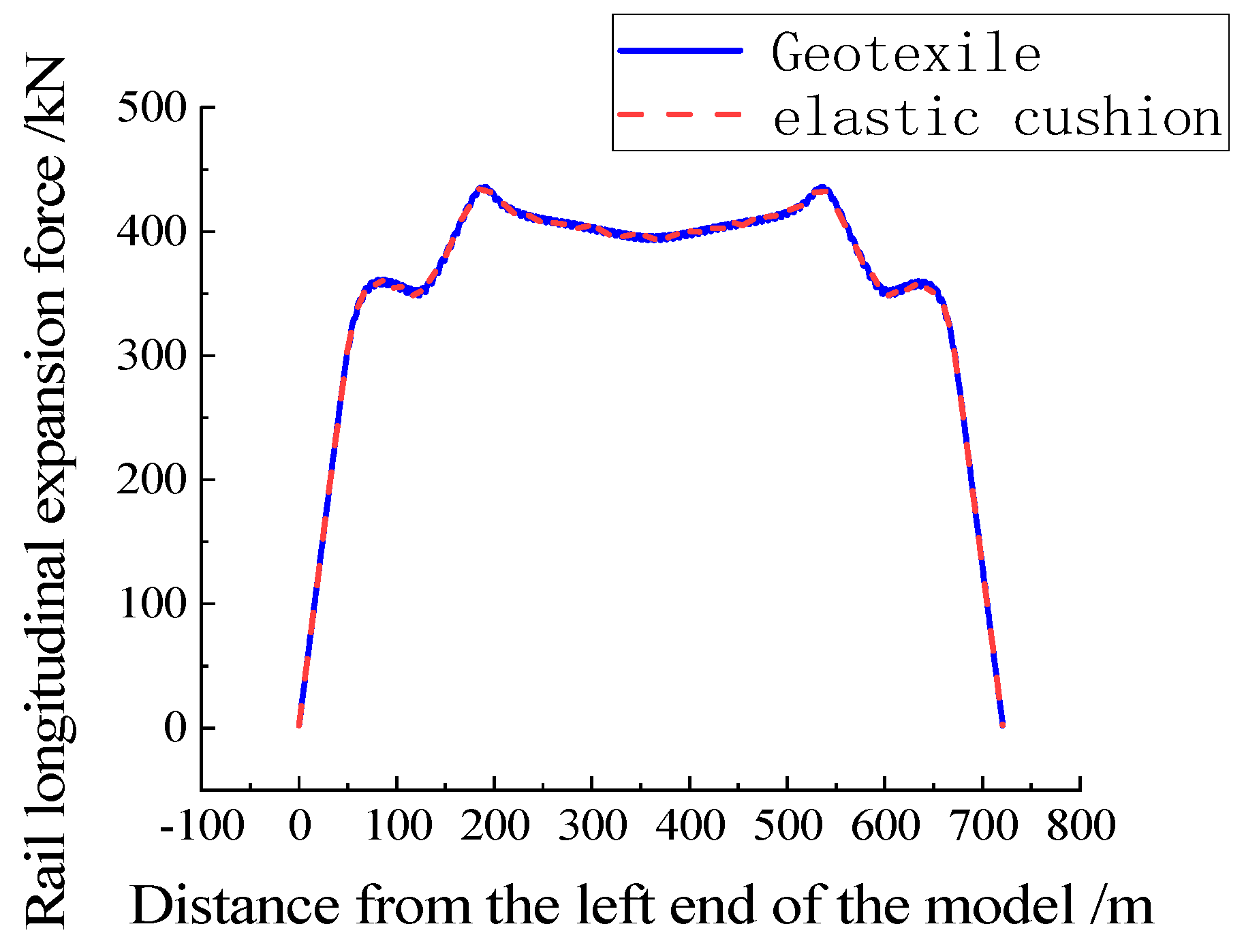
Under the temperature load, geotextile or elastic cushion laying on the bridge has no obvious influence on rail expansion force and rail longitudinal displacement, as shown in Figure 14 and Figure 15.
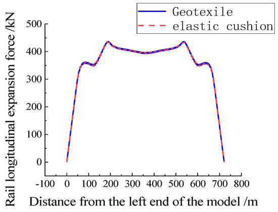
Figure 14.
Rail force under temperature load.
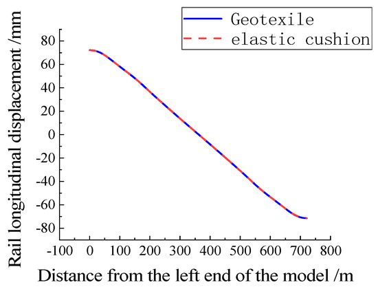
Figure 15.
Rail longitudinal displacement under temperature load.
In summary, from the perspective of a seamless line on the bridge, under the vertical load, laying geotextile or elastic cushion on the ballastless track on the long-span cable-stayed bridge has a great influence on the deflection force of the rail. Under the braking load and temperature load, the influence of geotextile or elastic cushion on the longitudinal deformation of the ballastless track seamless line on the long-span cable-stayed bridge is very small and can be ignored.
4.4. Strength Calculation of Seamless Tracks
The assessment of longitudinal forces in rails under the influence of temperature loads and train loads is a crucial indicator for ensuring the operational safety of Continuous Welded Rail (CWR) on high-speed railways. Temperature loads, on the one hand, cause thermal stress in rails and, on the other hand, trigger interaction between the beams and rails, resulting in additional forces in the rails. Under train loads, the static loads of the train cause deflection in the bridge, leading to additional deflection forces in the rails. As the wheels pass over, dynamic bending stress is incurred in the rails; therefore, it is necessary to conduct a strength assessment of the rails.
4.4.1. Thermal Stress in Rails
The Dongping long-span cable-stayed bridge is located in Foshan. According to the design parameters provided by the engineering design institute, the maximum rail temperature is 58.1 °C, the minimum rail temperature is 2.8 °C, and the locked rail temperature is Te = 30 ± 5 °C. The maximum temperature drop of the steel rail is
The temperature rise in the steel rail is
Thermal stress in rails:
In the previously mentioned formula, E represents the elastic modulus of the rail and takes the value of 2.1 × 10¹¹ Pa; α is the linear expansion coefficient of the rail and takes the value of 1.18 × 10⁻5. ΔTj is the temperature drop in the rail, and ΔTs is the temperature rise in the rail.
4.4.2. Dynamic Bending Stress of Rails
The train set has a maximum axle weight of 17 t with a fixed axle spacing of 2.5 m. The speed coefficient α = 1.0, the offload coefficient β = 0, and the lateral horizontal force coefficient f = 1.25. The dynamic bending stress at the bottom of the rail, calculated according to Formula (6):
represents dynamic bending stress at the bottom of the rail, is the static bending moment of the rail, α is the speed coefficient, β is the offload coefficient, and f is the lateral horizontal force coefficient; the rail cross-sectional area is A = 7745 mm2.
According to the Code for Design of Railway Continuous Welded Rail [28], the dynamic tensile bending stress at the bottom of the rail is 139.6 Mpa, and the dynamic compressive bending stress at the bottom of the rail is 179.9 Mpa.
4.4.3. Rail Braking Stress
Using the standard train live load diagram, the braking force coefficient is 0.164. The rail stress is obtained by dividing the rail force by the cross-sectional area of the rail. As shown in Figure 11, when a geotextile is laid on the bridge, the maximum braking compressive stress in the rail is 3.47 Mpa, and the maximum braking tensile stress in the rail is 3.49 Mpa. When an elastic cushion is laid on the bridge, the maximum braking compressive stress in the rail is 3.44 Mpa, and the maximum braking tensile stress in the rail is 3.43 Mpa.
4.4.4. Additional Stress in Rails
When a geotextile is laid on the bridge, the maximum bending compressive stress in the rail is 16 Mpa. Under temperature load, the maximum tensile/compressive stress in the rail is 56.3 Mpa. The additional rail stress is taken as the greater of the two values, thus taking 56.3 Mpa.
As stipulated in the Code for the Design of Railway Continuous Welded Rail, the stress experienced by the rail should be less than the allowable stress for the rail:
Based on the calculated results, the maximum additional stress is 56.3 Mpa, the thermal stress in rails is 82 Mpa, the rail braking stress is 3.49 Mpa, the dynamic bending stress of rails is 139.6 Mpa, and the total stress on the rail is 281.4 Mpa; this value is below the permissible stress of 351.5 Mpa, providing a sufficient margin. Similarly, the total stress experienced by the rail when an elastic layer is laid can be obtained is 281.3 Mpa, below the permissible stress of 351.5 Mpa.
5. Influence of Geotextile and Elastic Cushion on Deformation of Track Structure on the Bridge
5.1. Vertical Load
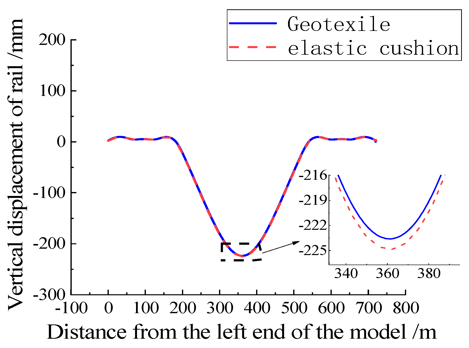
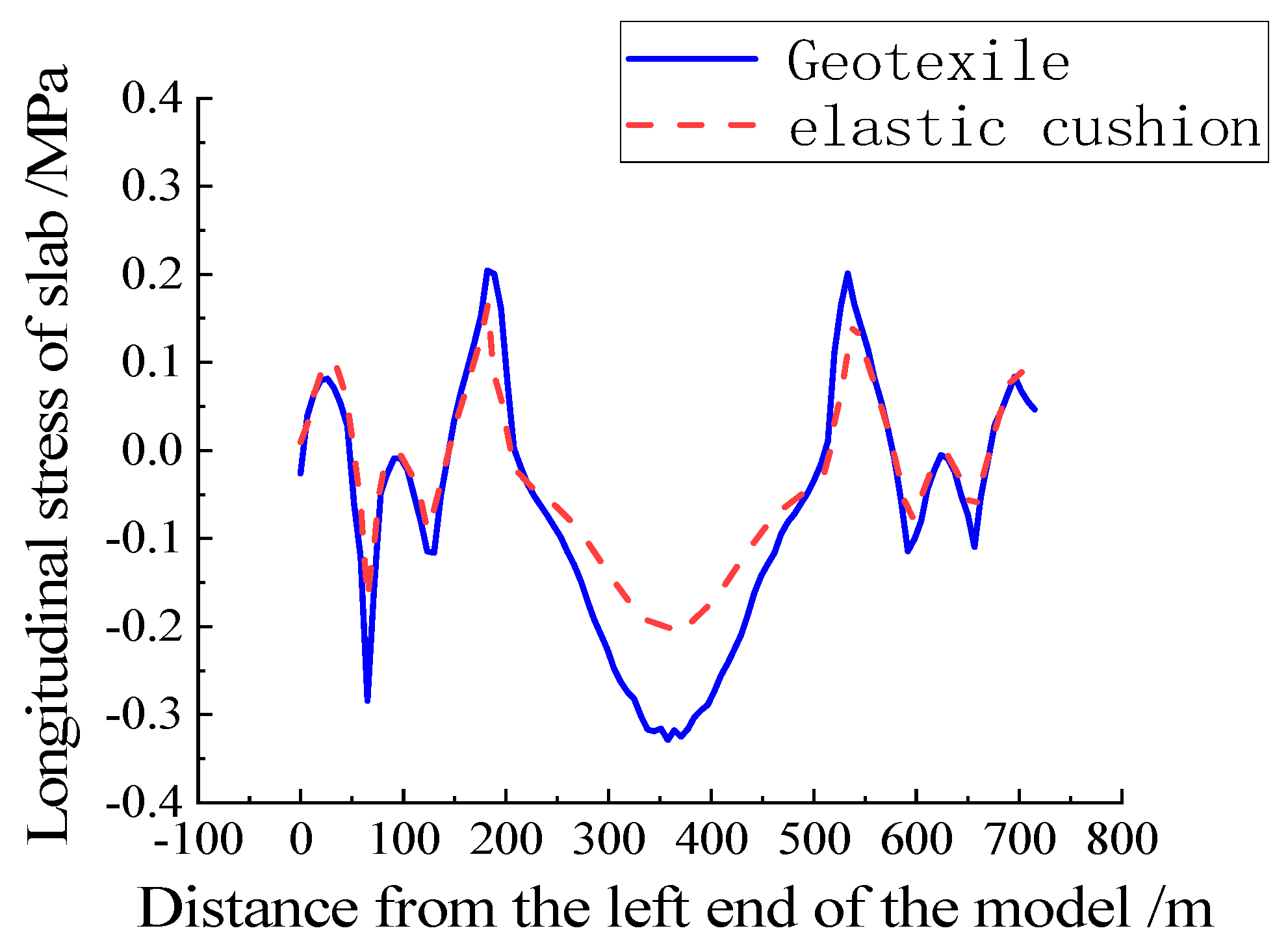
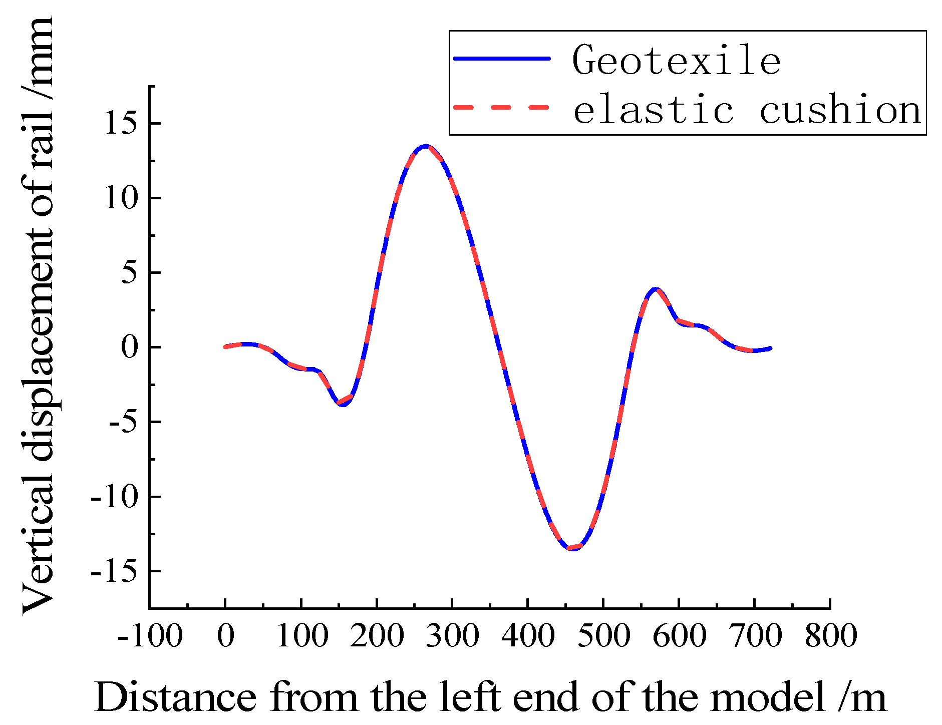
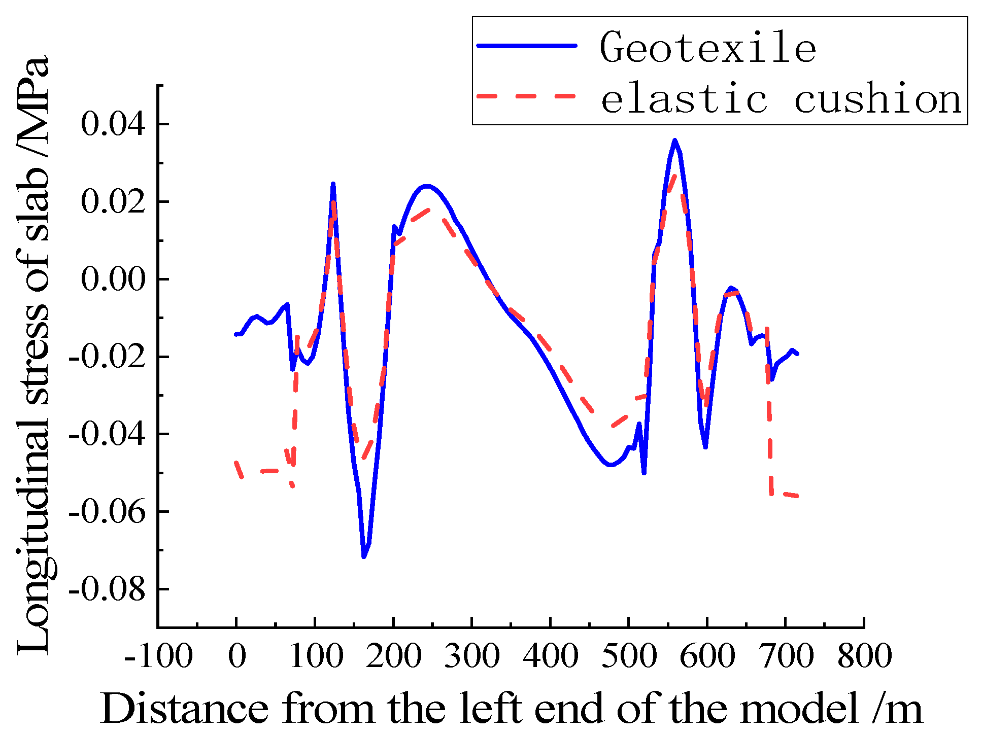
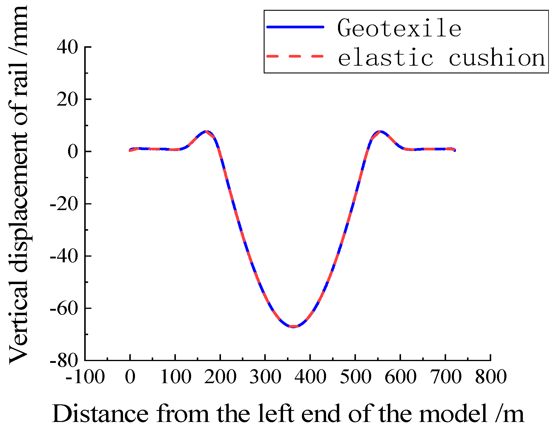
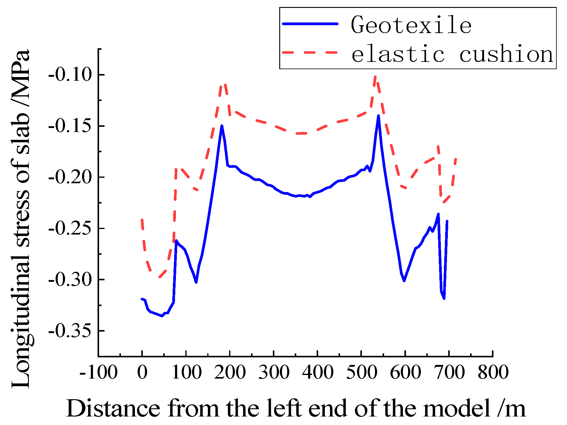
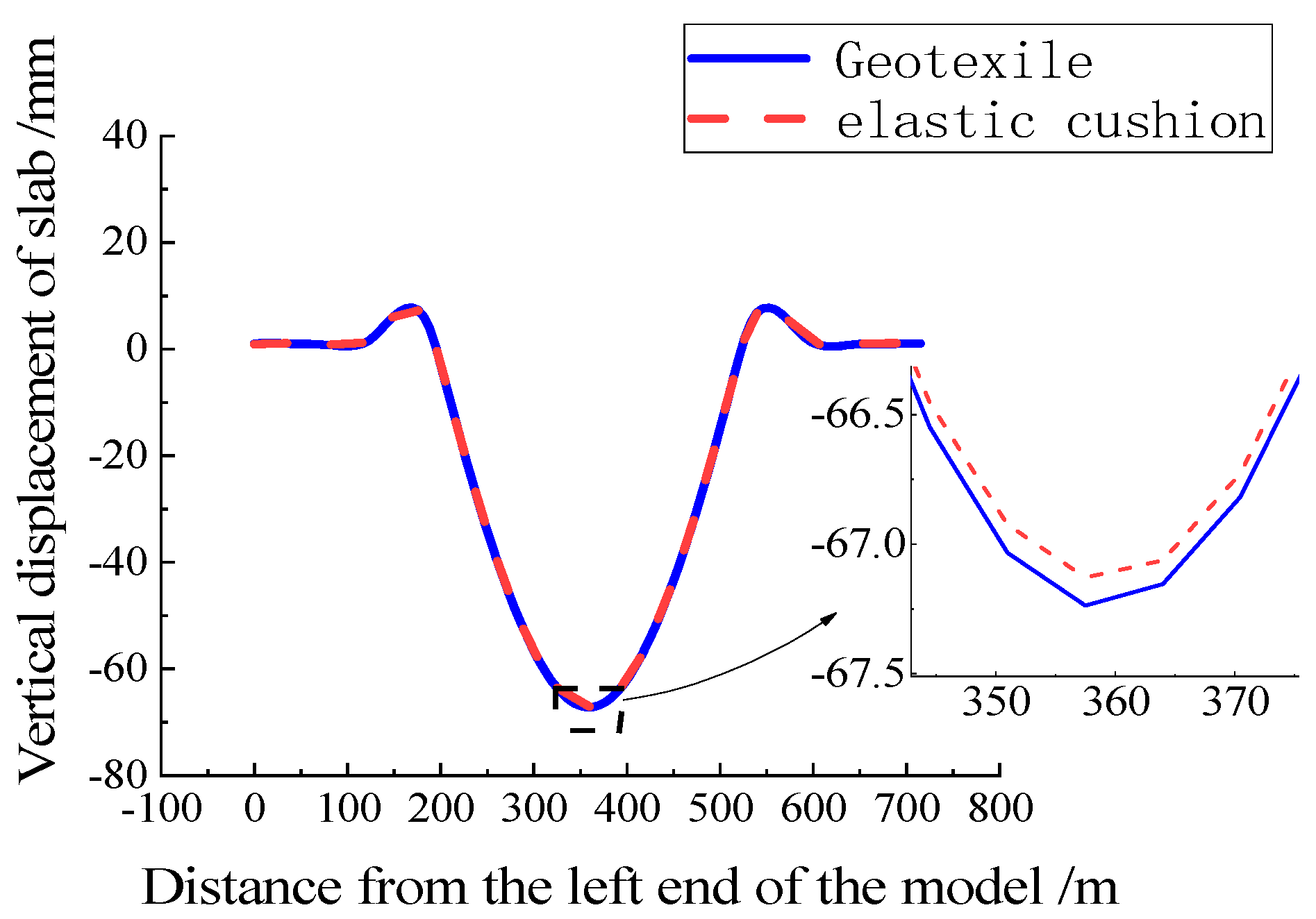
Figure 16 shows the deformation of the rail under vertical load. Because the stiffness of the elastic cushion layer is smaller than that of the geotextile, the vertical displacement of the rail when the elastic cushion layer is laid on the track on the bridge is 224.8 mm, larger than the vertical displacement of the rail when the geotextile isolation layer is laid, an increase of 1.2 mm. Figure 17 and Figure 18 show the longitudinal stress deformation of the track slab under vertical load. When the elastic cushion is laid on the ballastless track on the bridge, the longitudinal stress of the track slab is smaller than that when the geotextile is laid on the ballastless track on the bridge, and the peak value of the longitudinal stress of the track bed is reduced. For example, when the geotextile is laid, the longitudinal compressive stress of the cross-middle slab reaches the maximum of 0.33 Mpa, and when the elastic cushion is laid, the longitudinal compressive stress of the slab is 0.2 Mpa, and the longitudinal stress of the track slab is reduced by 0.13 Mpa. Neither the longitudinal stress of the elastic cushion laid on the ballastless track nor the geotextile slab on the bridge exceeds the compressive strength and tensile strength of the concrete.

Figure 16.
Rail displacement under vertical load.
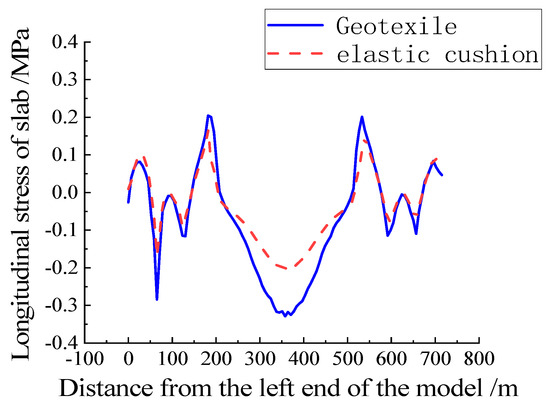
Figure 17.
Slab stress under vertical load.
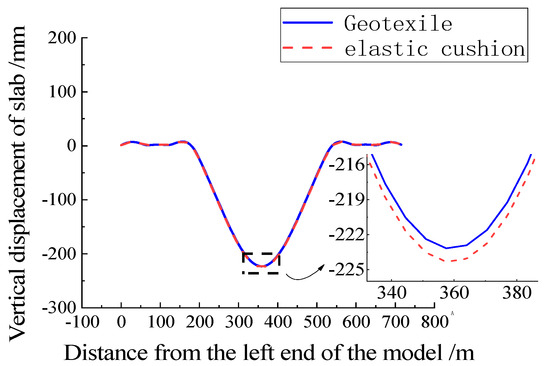
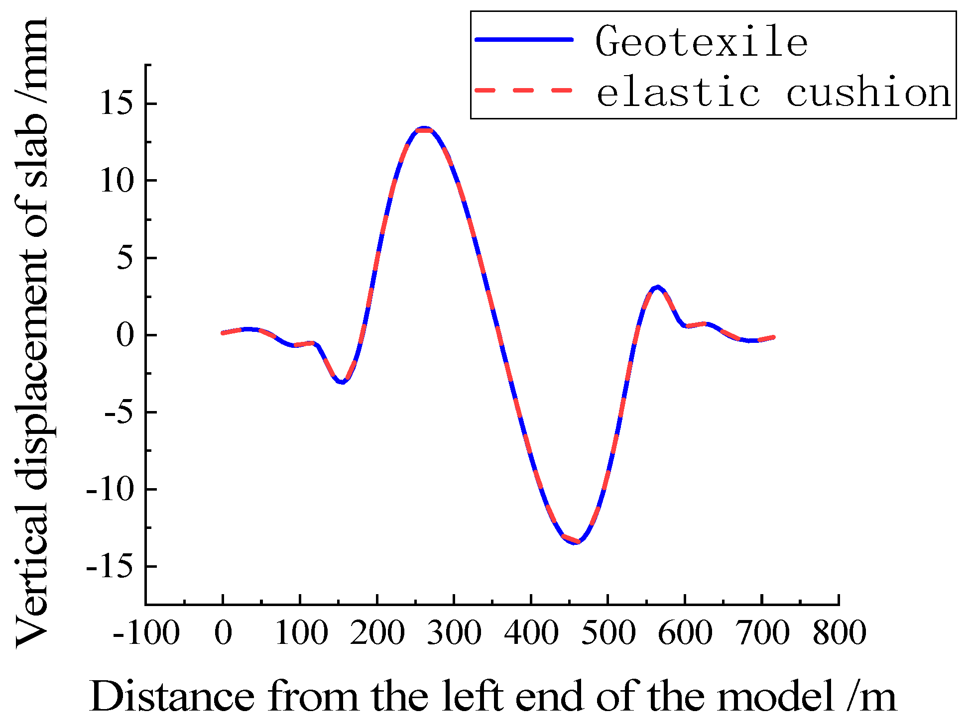
Figure 18.
Slab displacement under vertical load.
Under vertical load, laying an elastic cushion on the ballastless track directly reduces the overall stiffness of the bridge-ballastless track structure. For example, as showed in Figure 18, when the geotextile is laid, the vertical displacement of the track plate is 223.1 mm, and when the elastic cushion is laid, the vertical displacement of the track plate is 224.3 mm, and the displacement increases by 1.2 mm.
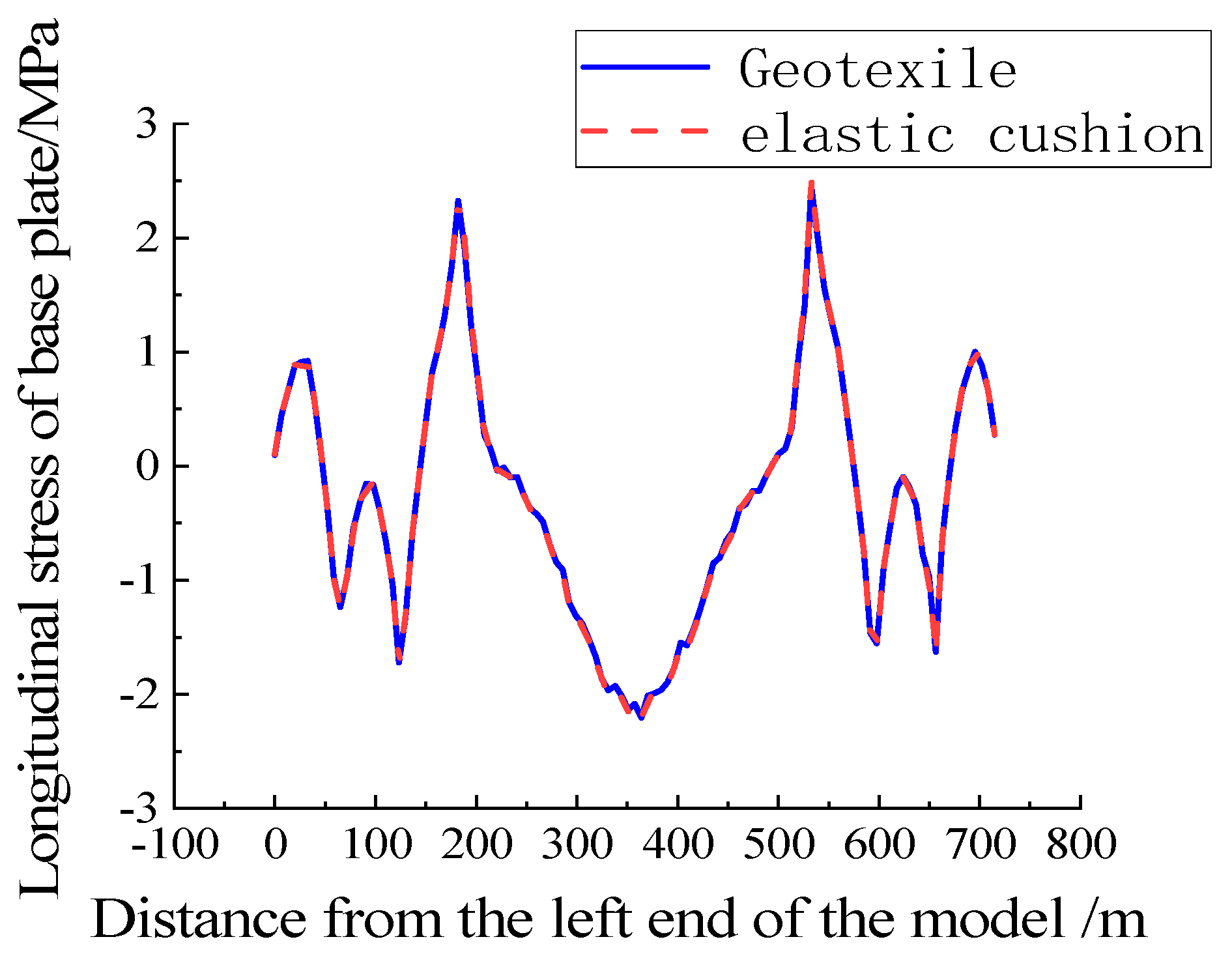
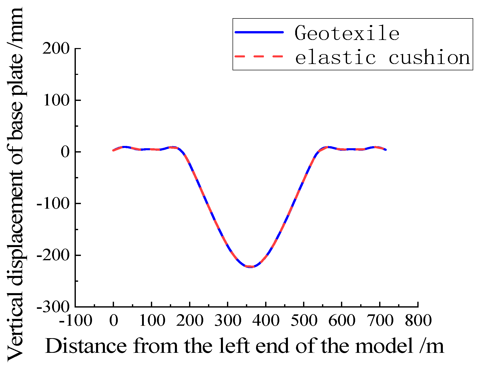
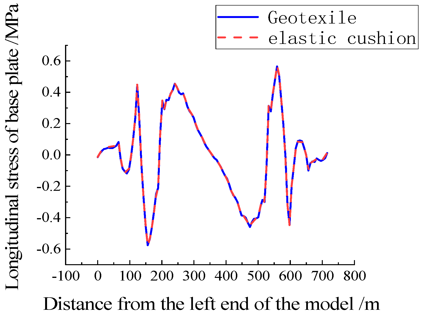
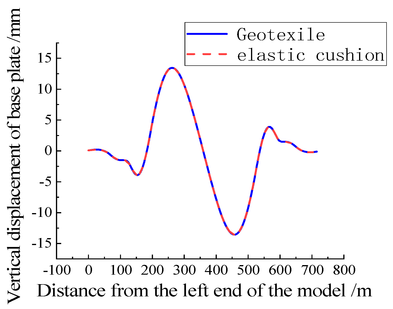
As shown in Figure 19, because the geotextile and elastic cushion have a direct impact on the structure of the slab and above and have little impact on the force of the base plate, the laying of elastic cushion on the bridge does not affect the stress distribution of the base plate, and the stress distribution and stress peak value are unchanged. The whole base plate is mainly compressive, and the tensile strength of the base plate near the bridge tower does not exceed the tensile strength and compressive strength of concrete. Under vertical load, when geotextile and elastic cushion are laid, the vertical displacement curve of the base plate almost coincides, which does not affect displacement distribution and peak displacement, as shown in Figure 20.
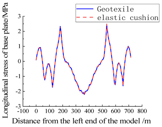
Figure 19.
Base plate stress under vertical load.
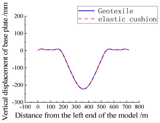
Figure 20.
Base plate displacement under vertical load.
5.2. Brake Load
Figure 21 shows the distribution of rail vertical displacement under braking load. The distribution law and value of rail vertical displacement are almost the same when the geotextile isolation layer and elastic cushion layer are laid. The maximum value of rail vertical displacement is located near the bridge tower on the side of the main beam.

Figure 21.
Rail displacement under braking load.
It can be seen from Figure 22 that the laying of an elastic cushion on the ballastless track on the bridge will change the longitudinal stress distribution of the bed slab on both sides and reduce the peak longitudinal stress of the bed slab. Under the braking load, the maximum braking stress values of the bed plate are 0.031 Mpa and −0.072 Mpa, respectively. However, the longitudinal stress of slabs did not exceed the tensile strength and compressive strength of the concrete when applying the geotextile or elastic cushion. Figure 23 shows the vertical displacement distribution characteristics of the plate are consistent with the rail.
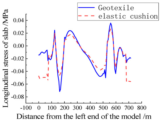
Figure 22.
Slab stress under braking load.
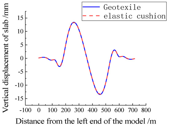
Figure 23.
Slab displacement under braking load.
From Figure 24, it can be seen that laying an elastic cushion on the bridge has no effect on the stress distribution of the base plate, and the stress distribution and peak value have not changed. When laying geotextile, the maximum longitudinal tensile stress and compressive stress of the base plate are 0.57 Mpa and 0.57 Mpa, respectively, which do not exceed the tensile and compressive strength of the concrete. Under braking load, the vertical displacement distribution of the base plate in Figure 25 is consistent with that of the steel rail and track plate. The laying of geotextile and elastic cushion base plate does not affect the vertical displacement distribution and peak vertical displacement.

Figure 24.
Base plate stress under braking load.
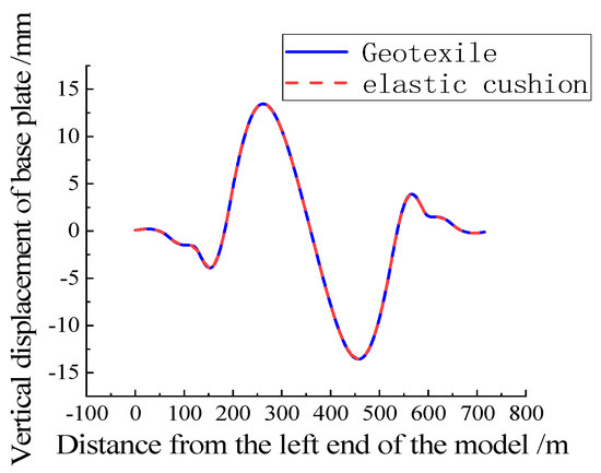
Figure 25.
Base plate displacement under braking load.
5.3. Temperature Load
Laying geotextile or elastic cushion under temperature load has little effect on the vertical displacement of rail, as shown in Figure 26. According to the results shown in Figure 27 under the temperature load, the track structure as a whole is under pressure, and laying an elastic cushion can reduce the longitudinal stress of the slab caused by temperature load. The maximum longitudinal pressure of the slab is 0.34 Mpa, which is less than the compressive strength of concrete. Laying geotextile or elastic cushion under temperature load has little effect on the vertical displacement ofslab, as shown in Figure 28.
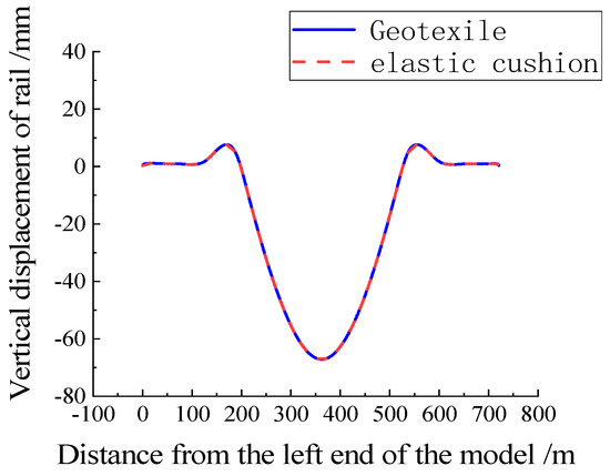
Figure 26.
Rail displacement under temperature load.
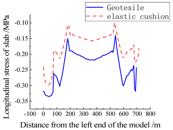
Figure 27.
Track slab stress under temperature load.
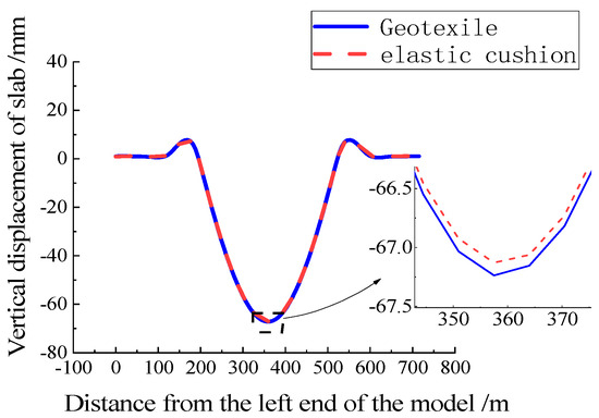
Figure 28.
Track slab displacement under temperature load.
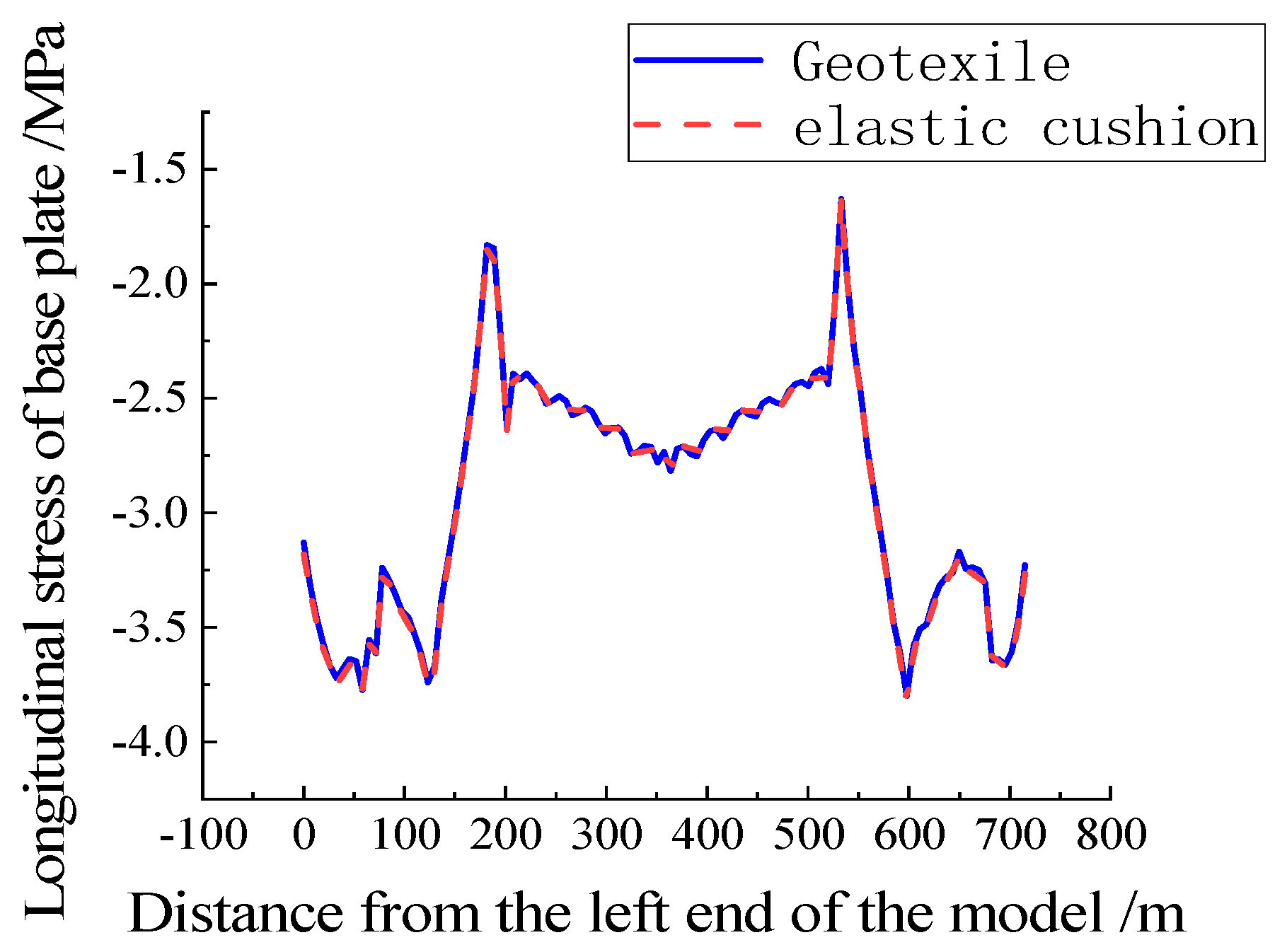
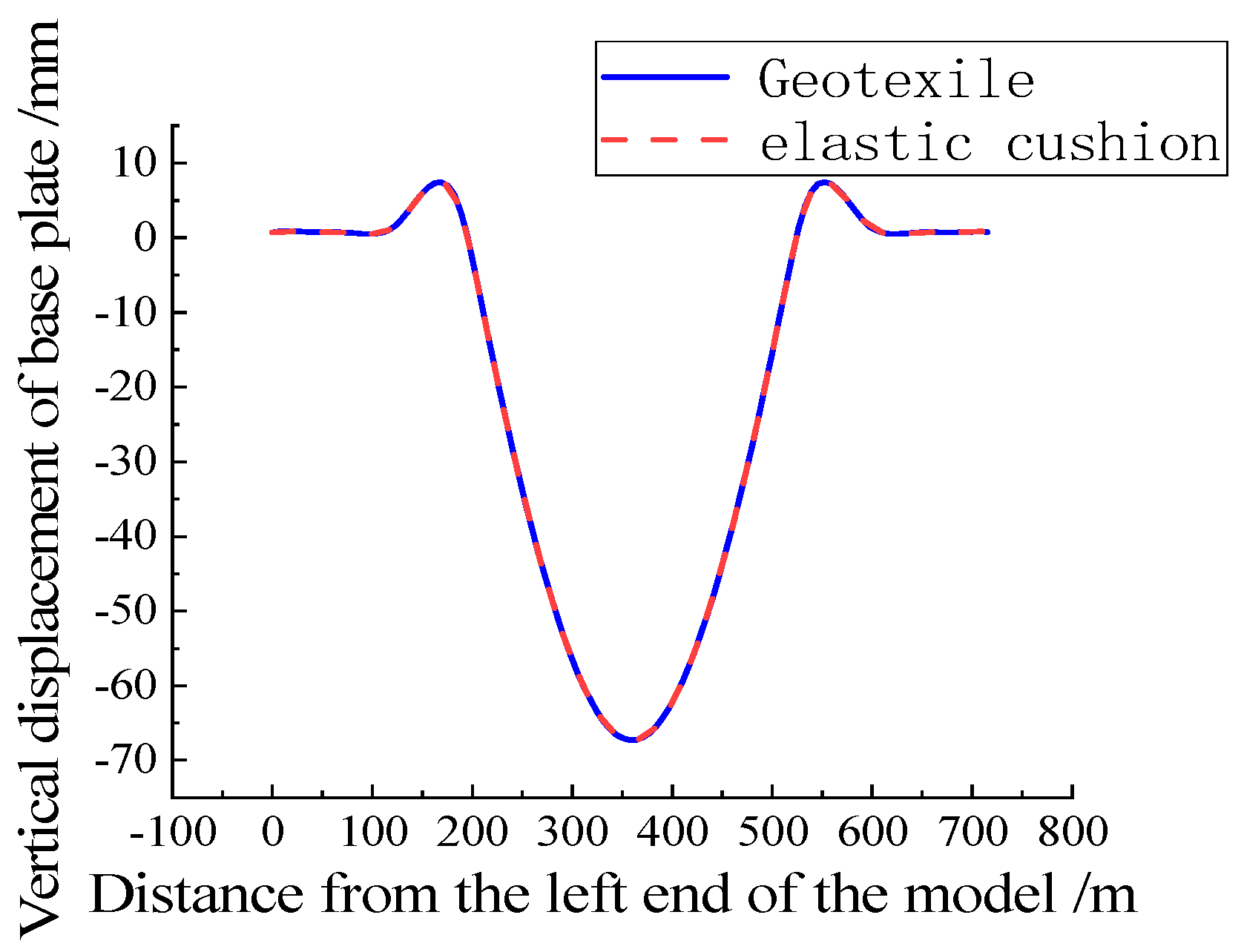
From Figure 29, it can be seen that under temperature load, the laying of elastic cushion on the bridge has no effect on the stress distribution of the base plate, and the stress distribution and peak value remain unchanged. The base plate is under overall pressure, with a maximum longitudinal compressive stress of −3.82 Mpa, which does not exceed the compressive strength of the concrete. The vertical displacement distribution of the base plate in Figure 30 is consistent with that of the steel rail and track slab. The maximum vertical displacement of the base plate is 67.3 mm, occurs at the midspan, and the laying of geotextile and elastic cushion base plate does not affect the vertical displacement distribution and peak vertical displacement.
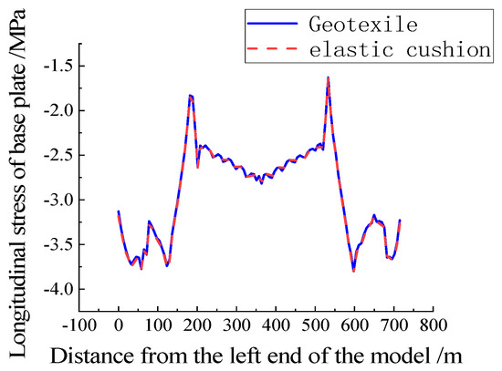
Figure 29.
Base plate stress under temperature load.

Figure 30.
Base plate displacement under temperature load.
6. Influence of Geotextile and Elastic Cushion on Track Seam Separation
Through the above analysis, it is found that the most unfavorable position of ballastless track deformation on the long-span bridge is in the main beam span and near the cable tower. In the simulation results, COPEN represents the distance between the contact layers, and the positive value represents the gap between the main surface and the subordinate surface. To converge easily, the finite element software (Abaqus6.14-1)allows for minimal interpenetration between layers. A negative COPEN value represents a tight fit between layers without the occurrence of seam separation.
6.1. Vertical Load
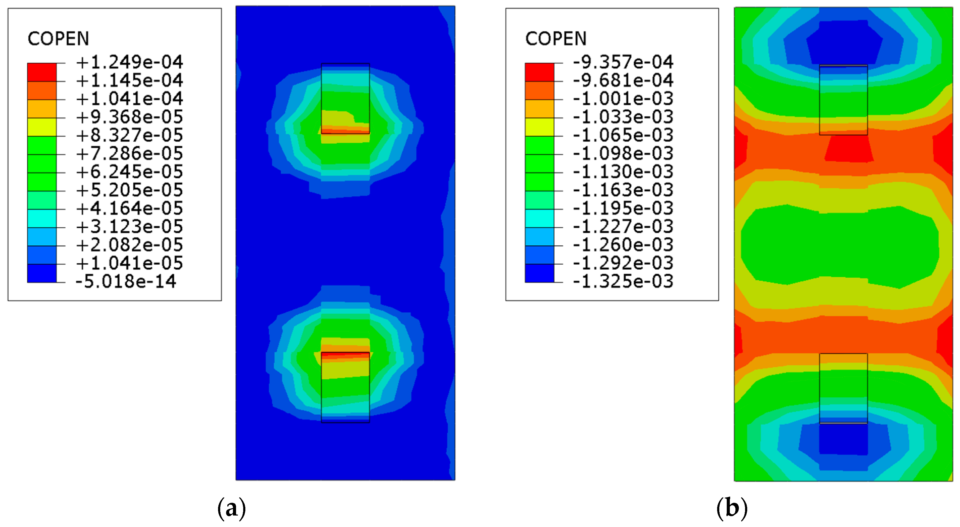
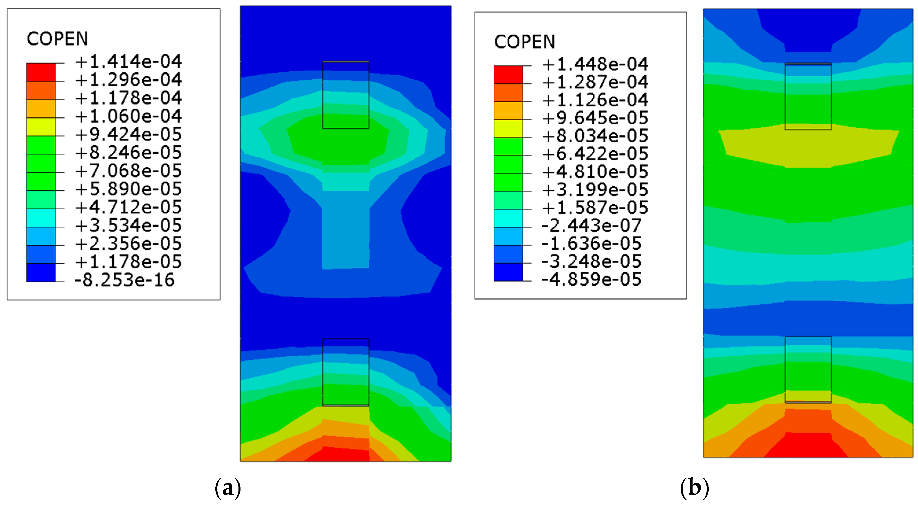
Under vertical load, when the geotextile is laid, the middle slab and base plate of the main beam span are separated, as shown in Figure 31a. The red area represents the position of seam separation, and the maximum seam separation height is 0.12 mm. The blue area indicates that the distance between the slab and the base plate is negative, which means that no seam separation occurs. When the elastic cushion is laid, the distance between the base plates at the middle span of the main beam is all negative, as shown in Figure 31b, indicating that no separation will occur between the layers under vertical load.
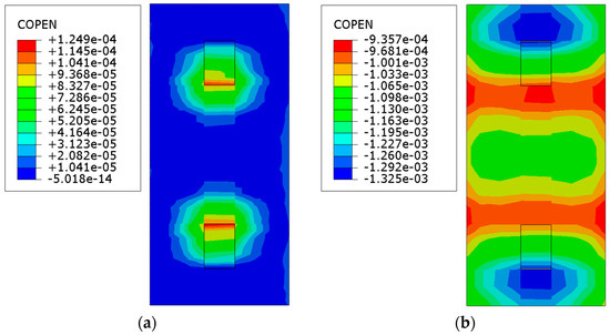
Figure 31.
State of the plates’ seam under vertical load at the middle of the bridge: (a) geotextile; (b) elastic cushion.
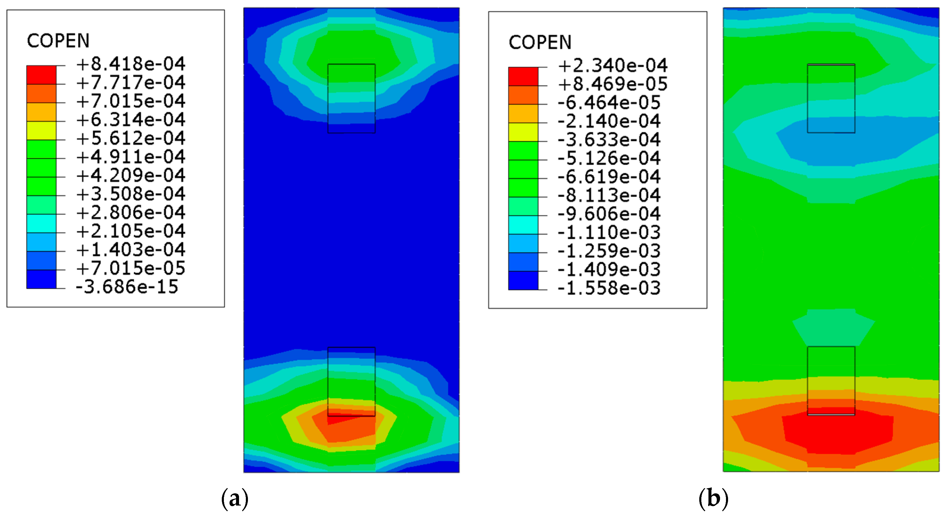
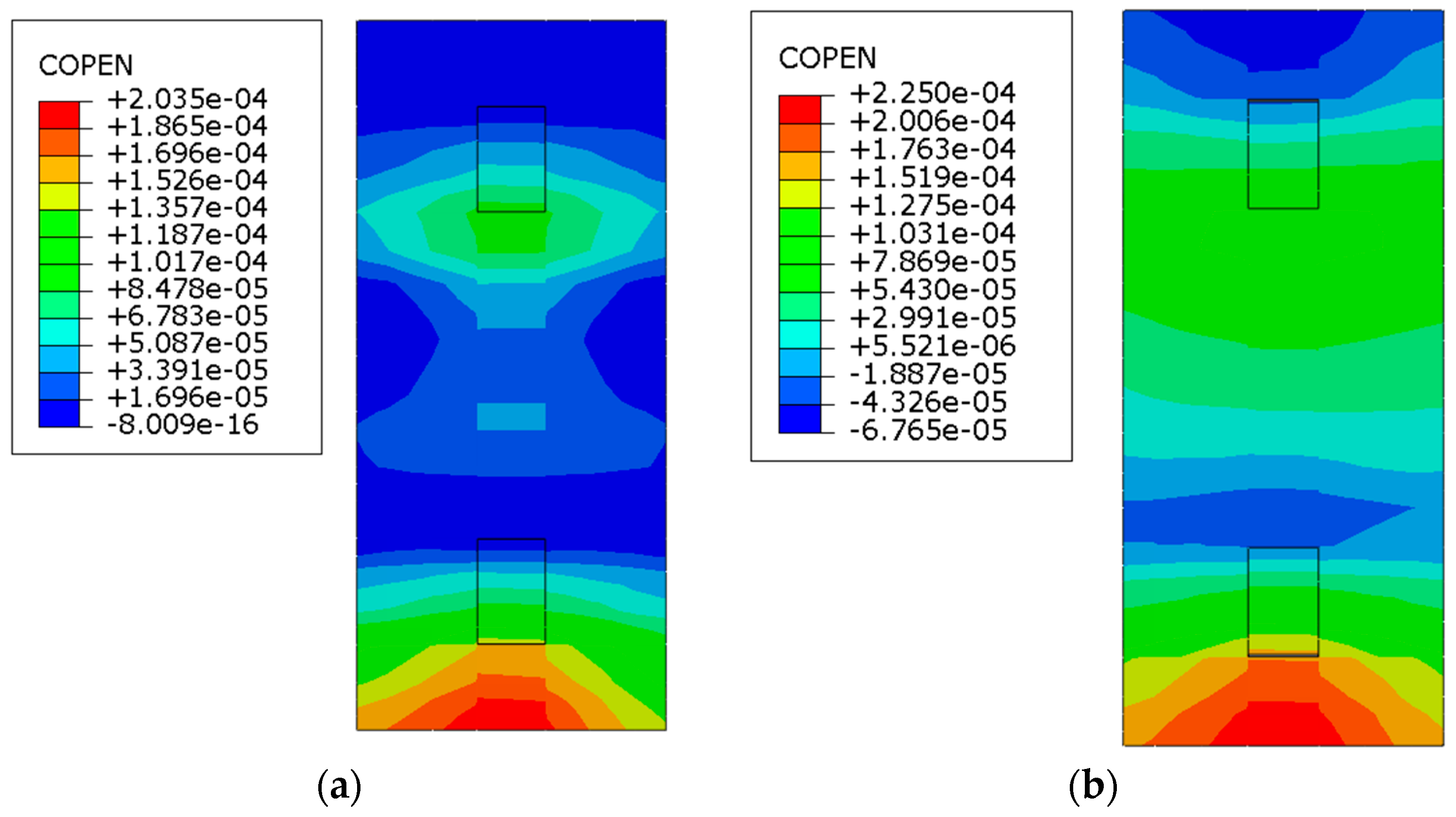
Under vertical load, there is a phenomenon of separation between the track slab and the base plate at the end of the limit groove of the base plate near the cable tower when laying geotextile, as shown in Figure 32a. The maximum gap position of the base plate is located in the red area of the limit groove, with a maximum gap height of 0.84 mm. When laying an elastic cushion layer near the abutment in Figure 32b, there is a phenomenon of separation between the track bed plate and the base plate near the end of the limit groove of the base plate. The maximum separation height is 0.23 mm, which is smaller than the separation height when laying geotextile, indicating that the elastic cushion layer can reduce the separation of the track bed plate.
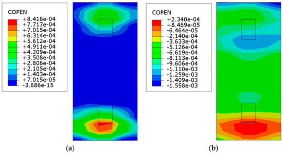
Figure 32.
State of the plates’ seam under vertical load near the cable tower: (a) geotextile; (b) elastic cushion.
6.2. Brake Load
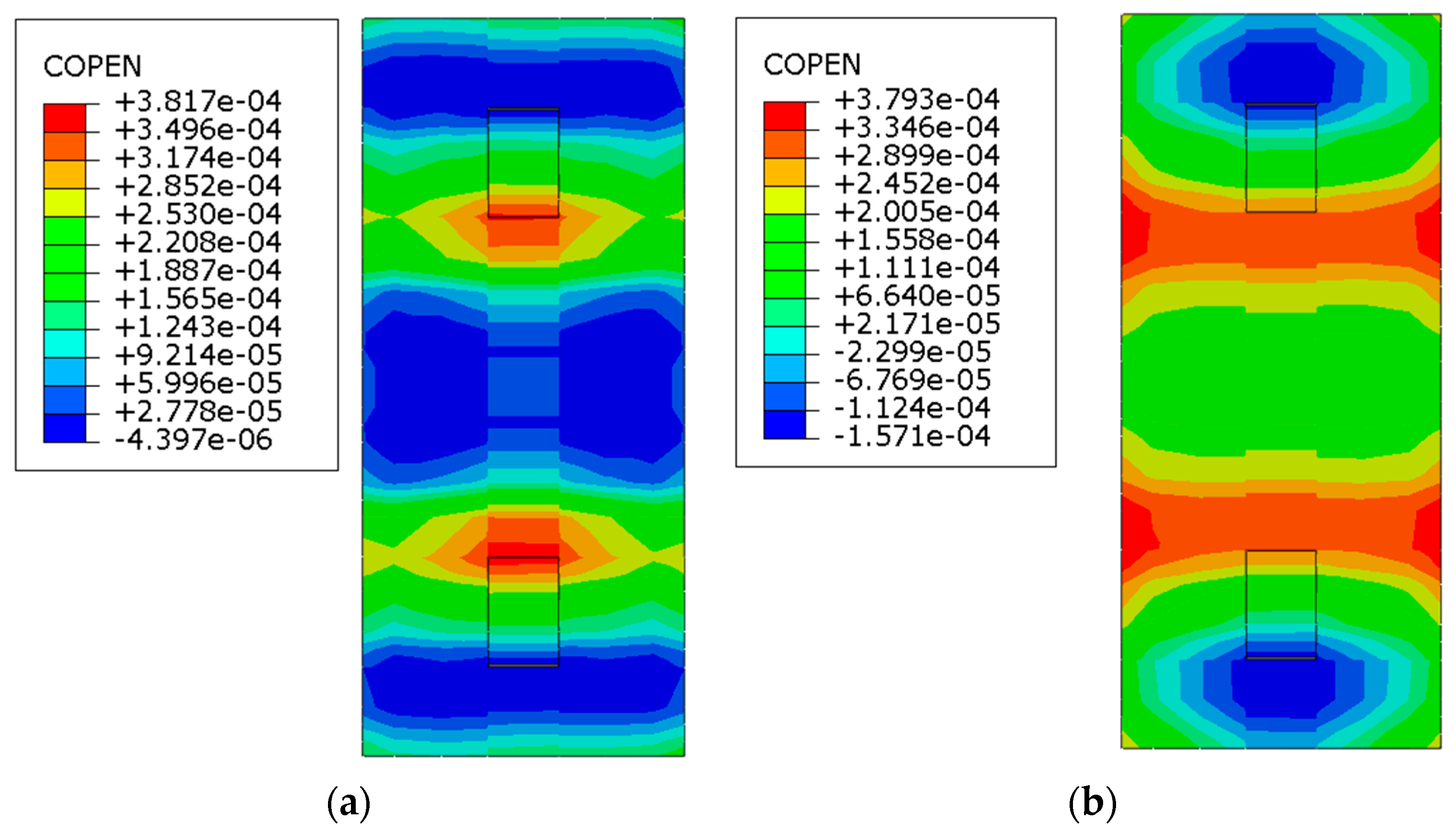
Under the braking load, the gap phenomenon occurs between the track slab and the base plate in the middle span of the main beam. The red area represents the gap, and the maximum separation height is 0.14 mm, as shown in Figure 33a. When the elastic cushion is laid, the gap between the bed plate and the base plate will also occur in the span of the main beam, as shown in Figure 33b. The maximum separation height is 0.14 mm. There is no difference In maximum separation height under braking load.
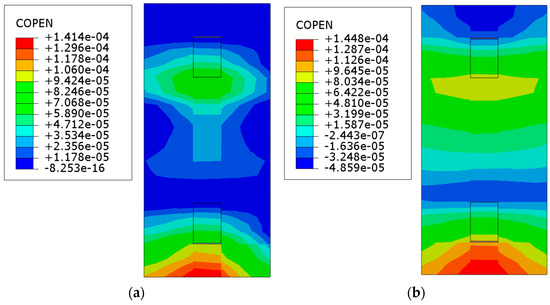
Figure 33.
State of the plates’ seam under brake load at the middle of the bridge: (a) geotextile; (b) elastic cushion.
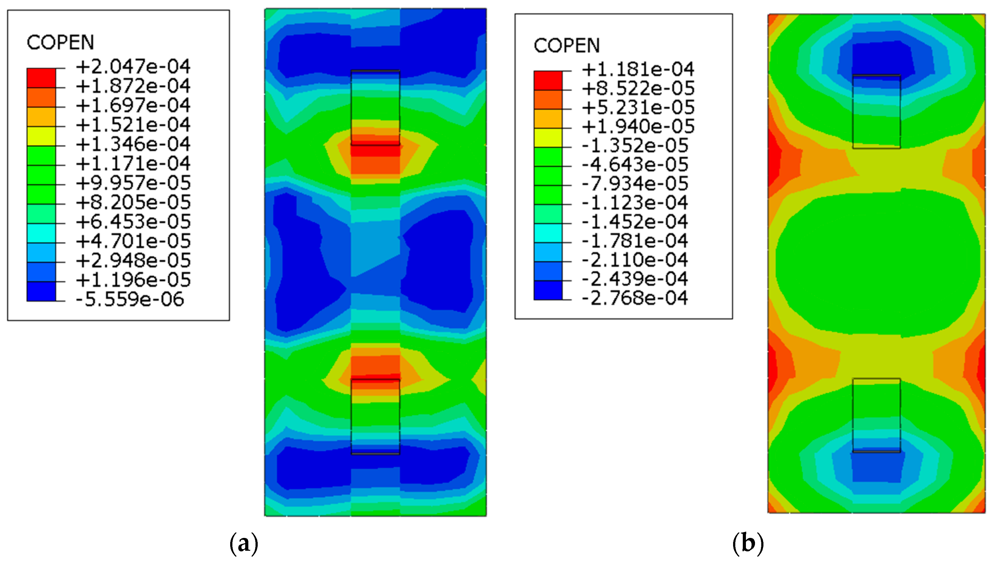
Under braking load, there is a phenomenon of separation between the track slab and the base plate near the end of the limit groove of the base plate near the cable tower when laying geotextile, as shown in Figure 34a. The maximum separation position is located in the red area of the limit groove at the middle of the bridge, with a maximum separation height of 0.20 mm. When laying the elastic cushion layer in Figure 34b, there is a phenomenon of separation between the track bed plate and the base plate near the end of the limit groove of the base plate near the abutment, with a maximum separation height of 0.22 mm, which is greater than the separation height when laying the geotextile. This indicates that the elastic cushion layer is not conducive to reducing the separation height of the track plate under braking load.
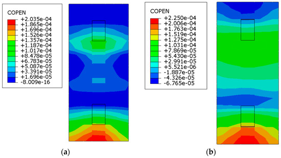
Figure 34.
State of the plates’ seam under brake load near the cable tower: (a) geotextile; (b) elastic cushion.
6.3. Temperature Load
Under the temperature load, when laying geotextile, the track slab and base plate are separated from each other, as shown in Figure 35a. The red area represents the maximum gap position, with a maximum separation height of 0.38 mm. When laying an elastic cushion, there is also a phenomenon of separation in the middle of the main beam span, as shown in Figure 35b, with a maximum separation height of 0.37 mm.

Figure 35.
State of the plates’ seam under temperature load at the middle of the bridge: (a) geotextile; (b) elastic cushion.
As shown in Figure 36a, under the action of temperature load, it is observed that there is a large area of gap between the track slab and the base plate when laying an elastic cushion near the cable tower. The maximum separation position is a maximum of 0.20 mm. When laying the elastic cushion layer in Figure 36b, the separation between the track bed plate and the base plate is 0.11 mm. When laying an elastic cushion layer, the separation height is less than that of the geotextile isolation layer.

Figure 36.
State of the plates’ seam under temperature load near the cable tower: (a) geotextile; (b) elastic cushion.
7. Conclusions
- (1)
- Under different load types, the geotextile and elastic cushion laid on the ballastless track on the long-span cable-stayed bridge have little influence on the longitudinal mechanical characteristics of the seamless line. Deformation in the track is within allowable limits; it can be considered a priority to use geotextiles when laying ballastless tracks.
- (2)
- When an elastic layer is laid, the total stress of the seamless track rail is 281.4 MPa. When geotextile is laid, the total stress of the seamless track rail is 281.3 MPa. The material used for laying has a minimal impact on the strength calculation of the rail, and it is within the safety range.
- (3)
- Under different load types, when the geotextile is laid on the ballastless track on the long-span cable-stayed bridge, the longitudinal stress of the track structure does not exceed the allowable strength of concrete. Under vertical load, braking load, and temperature load, laying elastic cushion, the stress peak value of the plate can be reduced by 0.13 MPa, 0.025 MPa, and 0.06 MPa, respectively.
- (4)
- The elastic cushion laid on the ballastless track of the long-span cable-stayed bridge can reduce the seam height of the track slab and the base plate near the cable tower or restrain the generation of seam under vertical load; under the braking load and temperature load, laying elastic cushion or geotextile has no obvious effect on inhibiting the separation of track structure, but the separation height is less than 0.4 mm.
- (5)
- Compared with laying geotextile, laying elastic cushion on a ballastless track on a long-span cable-stayed bridge has advantages in statics; when the geotextile is laid on the ballastless track on the bridge, although some indexes are greater than the elastic cushion, they do not exceed the standard, which indicates that it is feasible to lay the geotextile on the ballastless track on the long-span cable-stayed bridge. To reduce engineering costs or the complexity of future maintenance, geotextile isolation layers can be considered.
- (6)
- This paper only analyzes the difference between geotextile and elastic cushions from the perspective of statics. In the future, it will be necessary to analyze the difference between geotextile and elastic cushions from the perspective of dynamics and give a more comprehensive analysis compared with other codes of practice like AASHTO and conclusion, which is also the next work goal and direction. Areas such as how to replace the elastic cushion after it is damaged and the law of force change are also good directions of study.
Author Contributions
Methodology and formal analysis, J.C. (Jiasheng Cai), J.C. (Jinjie Chen), and J.W.; software, X.S.; formal analysis, R.W.; writing—review and editing, Y.Y. All authors have read and agreed to the published version of the manuscript.
Funding
This research was funded by the National Key Research and Development Program of China, grant number 2021YFB2601000, Hebei Provincial Natural Science Foundation of China, grant numbers E2020210092 and E2021210142, A Hundred Excellent Innovative Talents Support Project in Colleges and Universities in Hebei, grant number SLRC2019036, and the Funded Project for Innovative Graduates in Hebei, grant number CXZZBS2023135.
Institutional Review Board Statement
Not applicable.
Informed Consent Statement
Not applicable.
Data Availability Statement
The data presented in this study are available on request from the corresponding author. The data are not publicly available due to privacy.
Conflicts of Interest
The authors declare that no conflict of interest.
References
- Chen, L.; Zhou, Y. Development and Practice of High-speed Railway Bridge Technology in China. High Speed Railw. Technol. 2020, 11, 27–32. [Google Scholar]
- Li, D.; Wen, W.; Yan, A.; Wang, B.; Zhang, Z. Engineering Practice of Laying Ballastless Track on Long Span Cable-stayed Bridge. J. Railw. Eng. Soc. 2020, 37, 78–82. [Google Scholar]
- Zuo, J. Applicability Research on the Low-pylon Cable-stayed Bridge to Ballastless Track in Shangqiu-Hefei-Hangzhou Railway. J. Railw. Eng. Soc. 2018, 35, 36–40. [Google Scholar]
- Yang, H.; Li, H.; Yan, Z.; Jiao, Y.; Jian, F.; Li, J.; Yang, X. Design and Research on High-Speed Railway Long-span Mixed Beam Cable-Stayed Bridge with Ballastless Track. J. Railw. Stand. Des. 2021, 65, 83–88. [Google Scholar]
- Sheng, X.; Zheng, W.; Zhu, Z.; Yan, A.; Qin, Y. Ganjiang Bridge: A high-speed railway long-span cable-stayed bridge laying ballastless tracks. Struct. Eng. Int. 2019, 31, 40–44. [Google Scholar] [CrossRef]
- Zhu, Z.; Yan, M.; Li, X.; Sheng, X.; Gao, Y.; Yu, Z. Deformation Adaptability of Long-Span Cable-Stayed Bridge and Ballastless Track Structure. Chin. Railw. Sci. 2019, 40, 16–24. [Google Scholar]
- Han, Z.; Zhu, S.; Zhai, W.; Zhu, B. Static and dynamic effects of train-track-bridge system subject to environment-induced deformation of long-span railway bridge. Proc. Inst. Mech. Eng. Part F J. Rail Rapid Transit 2023, 237, 93–103. [Google Scholar] [CrossRef]
- Sheng, X.; Zheng, W.; Wu, J.; Zhang, H. Influence of local deformation mode of cable-stayed bridge on unballasted tracks: Experimental research. Adv. Civ. Eng. 2020, 6, 2316524. [Google Scholar] [CrossRef]
- Zheng, W.; Sheng, X.; Zhu, Z.; He, H. Experimental study on deformation characteristics of ballastless tracks under downward bending deformation of long-span cable-stayed bridge. Eng. Struct. 2020, 210, 110363. [Google Scholar] [CrossRef]
- Zheng, W.; Sheng, X.; Zhu, Z.; Shi, T. Effect of reverse bending deformation of large-span cable-stayed bridge on ballastless tracks’ behaviors. Struct. Eng. Mech. 2021, 80, 169–179. [Google Scholar]
- Sheng, X.; Zheng, W.; Zhu, Z. Mechanical behaviors and fatigue performances of ballastless tracks laid on long-span cable-stayed bridges with different arrangements. Sensors 2019, 19, 4195. [Google Scholar] [CrossRef] [PubMed]
- Qin, S.; Han, S.; Li, S. In-situ testing and finite element model updating of a long-span cable-stayed bridge with ballastless track. Structures 2022, 45, 1412–1423. [Google Scholar] [CrossRef]
- Wang, S.; Luo, J.; Zhu, S.; Han, Z.; Zhao, G. Random dynamic analysis on a high-speed train moving over a long-span cable-stayed bridge. Int. J. Rail Transp. 2022, 10, 331–351. [Google Scholar] [CrossRef]
- Li, D. Feasibility Study and Design Optimization of Ballastless Track for 450 m Main Span Cable-stayed Bridge of High-Speed Railways. J. Railw. Stand. Des. 2023, 67, 24–29. [Google Scholar]
- Xie, H.; Kou, S.; Xu, L.; Huang, J.; Liu, F. Mechanical Characteristics of Ballastless Track System on Long-span Cable-stayed Bridge. J. Railw. Eng. 2022, 62, 1–8. [Google Scholar]
- Qing, Y. Research on Adaptability of Ballastless Track of High-speed Railway with Long-span Stayed-cable Bridge. High Speed Railw. Technol. 2020, 11, 22–27. [Google Scholar]
- Sheng, X.; Zheng, W.; Zhu, Z.; Qin, Y.; Guo, J. Full-scale fatigue test of unit-plate ballastless track laid on long-span cable-stayed bridge. Constr. Build. Mater. 2020, 247, 118601. [Google Scholar] [CrossRef]
- Cai, X.; Liu, W.; Xie, K.; Zhu, W. Layout Optimization of Rail Expansion Joint on Long-Span Cable-Stayed Bridge for High-Speed Railway. Adv. Civ. Eng. 2020, 5, 8855140. [Google Scholar] [CrossRef]
- Zhao, G.; Cai, X.; Liu, W.; Wang, T.; Wang, T. Mechanical Properties and Structural Optimization of Continuous Welded Rail on Super-Long-Span Suspension Bridges for High-Speed Railway. Appl. Sci. 2021, 12, 305. [Google Scholar] [CrossRef]
- Yan, B.; Kuang, W.; Gan, R.; Xie, H.; Huang, J. Track–Bridge Interaction of CWR on Chinese Large-Span Bridge of High-Speed Railway. Appl. Sci. 2022, 12, 9100. [Google Scholar] [CrossRef]
- Gou, H.; Zhao, T.; Qin, S.; Zheng, X.; Pipinato, A.; Bao, Y. In-situ testing and model updating of a long-span cable-stayed railway bridge with hybrid girders subjected to a running train. Eng. Struct. 2022, 253, 113823. [Google Scholar] [CrossRef]
- Wang, F.; Dai, G.; Liu, Y.; Ge, H.; Rao, H. Investigation of the Temperature Actions of Bridge Cables Based on Long-Term Measurement and the Gradient Boosted Regression Trees Method. Sensors 2023, 23, 5675. [Google Scholar] [CrossRef] [PubMed]
- Li, Y. Study on Variation Rules of Longitudinal Force of Continuous Welded Rails on Long-span Cable-stayed Bridge. J. Railw. Eng. Soc. 2012, 29, 42–46. [Google Scholar]
- Fan, Y.; Zhao, H.; Li, A.; Fang, Z. Experimental–Numerical Analysis on the Cable Vibration Behavior of a Long-Span Rail-Cum-Road Cable-Stayed Bridge under the Action of High-Speed Trains. Appl. Sci. 2023, 13, 11082. [Google Scholar]
- Ren, J.; Tian, G.; Feng, X.; Yan, Y. Influence of Rubber Pad Ageing on Dynamic Characteristics of CRTS I Slab Ballastless Track Structure. J. Railw. Eng. 2017, 517, 106–110. [Google Scholar]
- Liu, W.; Wang, J.; Du, X.; Zhao, Y.; Wang, M.; Liu, H.; Zhao, L. Technical Requirements of EPDM Isolation Layer Used in CRTS III-type Slab Ballastless Track. China Railw. 2018, 671, 64–70. [Google Scholar]
- TB10095-2020; Code for Design on Railway Cable-stayed Bridge. Chinese Standard GB/T: Beijing, China, 2020.
- TB10015-2012; Code for Design of Railway Continuous Welded Rail. Chinese Standard GB/T: Beijing, China, 2012.


Disclaimer/Publisher’s Note: The statements, opinions and data contained in all publications are solely those of the individual author(s) and contributor(s) and not of MDPI and/or the editor(s). MDPI and/or the editor(s) disclaim responsibility for any injury to people or property resulting from any ideas, methods, instructions or products referred to in the content. |
© 2023 by the authors. Licensee MDPI, Basel, Switzerland. This article is an open access article distributed under the terms and conditions of the Creative Commons Attribution (CC BY) license (https://creativecommons.org/licenses/by/4.0/).