Abstract
Additive manufacturing (AM) of polyetheretherketone (PEEK) biomaterials using the material-extrusion (MEX) method has been studied for years. Because of the challenging manufacturing process, precisely controlling printing parameters is crucial. This study aimed to investigate the effects of printing parameters such as orientation and position of printing on mechanical properties. Thus, 34 samples were printed using PEEK filament and the MEX process. Samples were divided into two main groups (A,B) according to their printing orientations (A: groups 1–3) and positions on the build plate (B: groups 4–8). Mechanical tensile tests were performed to evaluate the effects of different printing orientations and positions on mechanical properties. The means of the tensile modulus in samples 3D-printed in XY (group 1), XZ (group 2), and ZX (group 3) orientations were not significantly different (p-value = 0.063). Groups 1 and 2 had smaller distributions than group 3 in the means of tensile strength. The t-test showed that the overall means of the measurements in groups 4–8 did not differ significantly (p-value = 0.315). The tensile tests indicated that printing in vertical and horizontal orientations had no significant influence on mechanical properties. There were no significant differences in mechanical strength between top/bottom printed samples in five different lateral positions. Reliability of printing with good mechanical properties could be a step forward to manufacturing patient-specific implants.
1. Introduction
The thermoplastic polymer polyetheretherketone (PEEK) is a member of the polyaryletherketone (PAEK) polymer family, with remarkable mechanical and physicochemical properties similar to natural bone [1,2,3,4,5]. Three decades ago, since confirming the biocompatibility of PAEK polymers, this polymeric material has been increasingly used as a biomaterial for medical implants, especially in orthopedic and spinal applications [1,2,3,4,5]. PAEK was commercialized in the industry in the 1980s and was offered as a biomaterial for implants in 1998 [6,7,8].
This unique material was studied and investigated for years in different fields of medicine, and can be used as patient-specific implants [4]. Properties possessed by PEEK materials—such as excellent biocompatibility, radiolucency, durability, strength, light weight, mechanical properties resembling human bone, cortical bone-like young’s modulus, and chemical and thermal resistance—have shown the potential such material as an alternative to conventional materials, considering titanium as a gold standard [4,9,10,11].
Additive manufacturing (AM), commonly known as three-dimensional (3D) printing technology has provided an excellent possibility creating complex structures in PEEK biomaterial [4,11].
AM of polymeric material can be conducted via two main printing technologies, such as powder bed fusion and material-extrusion (MEX) [12,13,14,15,16,17,18,19].
According to the study of Sharma et al. [20], the MEX technology allows the manufacturing of perfectly fitted customized patients-specific implants (PSIs). Moreover, the possibility of preoperative planning, shorter surgery time, and cost reduction are other benefits of integrating MEX technology at the point-of-care [11,21,22]. Commercially formulating PEEK into filaments for MEX printing is relatively new. High melting temperature (over 340 °C) and thermal gradients make the fabrication of high-performance PEEK parts challenging [10,22]. The studies of Verma et al. [4] and Baek et al. [22] showed that high melting temperatures, fast crystallization kinetics, and significant dimensional shrinkage when cooled might generate cavities inside the printed parts, which degrade the mechanical properties, printing geometry, surface roughness, and reliability of PEEK 3D-printed parts.
In the MEX method, it is essential to manage the temperature, as the strength of interlayer bonding, crystallinity of the polymer, and the deformation of printed parts are related to the heating and cooling rates [23,24,25,26,27,28]. Another notable barrier of implementation of MEX printing is the anisotropic mechanical characteristics of the 3D-printed parts, i.e., the mechanical strength between layers (in either the build-direction or z-direction) is weaker than the mechanical strength in the x- and y-direction. This anisotropic behavior often leads to layer delamination, which usually leads to brittle fracture properties. Some studies showed that other printing parameters, such as speed and orientation of printing and the temperature of the nozzle, bed, chamber, and drying protocol of PEEK filaments can also influence the properties of printed PEEK parts [22,24,29,30,31,32,33].
Yang et al. [34] looked into the relationship between different thermal conditions and crystallinity as well as mechanical properties. Their findings revealed that ambient and nozzle temperatures have a significant impact on the degree of crystallinity and tensile properties. Magri et al. [35] performed tensile tests on horizontally printed PEEK dog bone samples and suggested that an optimal tensile strength can be achieved for annealed parts post-printing. However, we would like to state that the majority of these studies either tested the mechanical properties of horizontally printed specimens or compared the mechanical properties of horizontally and vertically printed specimens. When horizontally printed specimens were used printed in the center of the build platform, the printed strands carried the majority of the stress, not the interface between layers. As a result, it is critical to determine the effect of process parameters on mechanical properties of 3D printed PEEK samples printed not only at the center of the build platform but also over the entire build chamber.
On the other hand, point-of-care manufacturing is the projected future of the production of PSIs in medical centers. Therefore, addressing different printing parameters is important to ensure that 3D-printed products meet all clinically defined requirements.
Therefore, this study aimed to investigate the effects of printing parameters, including orientation of printing and position of print job on the build plate, on the mechanical properties and dimensional accuracy attributes of the MEX 3D-printed PEEK biomaterial.
The null hypothesis assumed that different positions of print jobs on the build plate would have no significant influence on the mechanical properties and dimensional accuracy characteristics of the 3D-printed PEEK parts. At the same time, the build orientations of printing affected the mechanical properties.
2. Materials and Methods
Thirty-four samples were printed as dog bones and pentagon towers in the current study using PEEK filament and the MEX technology. Samples were divided into two main groups according to their printing orientations (group A) and positions (group B). All printed parts were cooled down under the same atmospheric conditions. Mechanical tensile tests were performed to evaluate the effect of different printing orientations and positions on mechanical properties.
2.1. Printing Strategies
In this study, 34 samples, namely dog bones, short pentagon towers (height 80 mm), and tall pentagon towers (height 156 mm) were 3D-printed at the point-of-care according to their different printing settings. Computer-aided design (CAD) software SolidWorks (Dassault Systems SOLIDWORKS Corp., Waltham, MA, United States) was used to design and generate the standard tessellation language (STL) files of the test samples. They were exported into slicing software (Simplify 3D version 4.1.2, Cincinnati, OH, USA) and, along with printing parameters, printing files were built and uploaded into the 3D printer for the printing process [33,36].
Samples were printed in different lateral and top/bottom positions on the build plate and different printing orientations (XY, XZ, ZX) with similar nozzle size (0.4 mm diameter) and same build chamber temperature of 200 °C and build plate temperature of 250 °C. All parts were printed as filled structures, with a theoretic infill percentage of 100% and rectilinear internal and external infill patterns. Laminar airflow guaranteed homogeneous temperature distribution and therefore no temperature gradient within the building part [37].
As shown in Figure 1, samples of group A were printed in different orientations of XY (group 1), XZ (group 2), and ZX (group 3). Samples of group 1 were directly printed in dog bone shape, planar with their surface in Z-direction. The longitudinal axis was oriented along the x-axis of the build platform. The samples of group 2 were printed in rectangular bars with their surface tilted by 90°. On the other hand, group 3 samples were printed in pentagon towers [38,39].
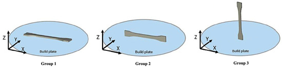
Figure 1.
Samples of group A were printed in different XY, XZ, and ZX orientations.
Dog bone samples of group 2 and group 3 were then milled out of rectangular bars and from each side of short pentagon towers, respectively. This strategy was implemented to have a consistent reporting and evaluation criteria in all the end-product specimens, i.e., dog-bone samples. Furthermore, group 3 samples were printed in excess to assess the reproducibility of printing in ZX orientation.
Group B was considered to assess the influence of different top/bottom and lateral positions of the part in the build room on its performance and repeatability in terms of mechanics. It is essential to mention that the printing process parameters for these groups were identical, and the only difference was the position of the part on the printer build plate. The printing orientation in group B samples was ZX; therefore, pentagon tower structures were considered [38,39].
Two similar tall towers, at one per build, were printed in each lateral position on the build plate. Each side of the tall pentagon towers was milled into two dog bones—one on top and one on the bottom (Figure 2).
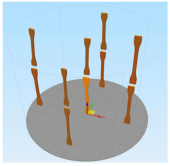
Figure 2.
Samples of group B were printed in different positions on the build job.
An overview of all groups, including their number of samples, their subgroups, and differences in production strategy, is given in Table 1. PEEK 3D-printed parts were manufactured at one per build.

Table 1.
Printed parts were divided into two main groups considering different printing strategies.
2.2. 3D Printing of Test Samples
In this study, samples were manufactured with MEX-based 3D printer (Kumovis R1, Kumovis GmbH, Munich, Germany).
Medical-grade PEEK filament (Evonik VESTAKEEP ® i4 G resin, Evonik Industries AG, Essen, Germany) with a 1.75 mm diameter was used in this study. This filament is a semicrystalline polymer with a density of 1.30 g/cm3 and tensile strength of 97 MPa. To prepare filaments for printing, every spool was dried 8 h before printing at 80 °C using an oven (Memmert GmbH + Co.KG, Buechenbach, Germany). The dried filament was loaded into the printer. Then the chamber, build plate, and nozzle were preheated to 200 °C, 250 °C, and 450 °C, respectively.
2.3. Geometrical and Mechanical Characterization
To assess dimensional accuracy, the definitive dimensions of printed parts in group 1 were determined with a calibrated digital micrometer (Mitutoyo Corp caliper, Kawasaki, Japan) [40]. The thickness of the middle of dog bones (dimension A), the width of one side of dog bones (dimension B), the width of the center of the dog bones (dimension C), and the length of the dog bones (dimension D) were measured (Figure 3).
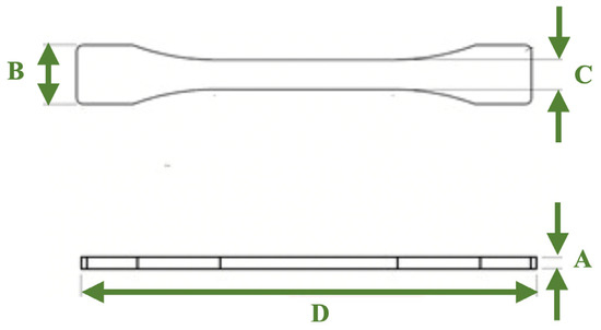
Figure 3.
Measured dimensions in dog bones of group 1. (A) thickness of the middle, (B) width of one side, (C) width of the center, (D) length of the dog bones.
Before the tensile test, the samples were acclimatized in a condition for 24 h at 23 °C/50% r.h. The Zwick/Roell Z100 device (Zwick Roell GmbH & Co., Ulm, Germany) was used for the tensile test. The LaserXtens 2-220 HP optical extensometer (Zwick Roell GmbH & Co., Ulm, Germany) was used to contactless measure sample strain. We set the test speed to 5 mm/min, tensile modulus 1 mm/min, preload 0.1 MPa, and gauge length (standard travel) 20 mm. In contrast to the norm ISO 527-2, the elastic region between 20 MPa and 30 MPa was used to determine the tensile modulus of each measurement by linear regression, not the 0.05–0.25% strain interval.
2.4. Statistical Analysis
Statistical analyses were done with the software R4.2.1. Measurement series of tensile modulus () and maximum strength () were checked using qq plots and Shapiro tests to determine if data were normally distributed. If so, ANOVA analysis was performed to check whether the variances of the measurement groups had the same theoretical means. Pairwise comparisons were made by Tukey’s honest significant difference test (HSD). If nonnormality was the case, the Kruskal–Wallis test was applied to check variances. Additionally, pairwise comparisons were made by pairwise Wilcox test.
To check whether the Z-position (top and bottom) or the towers in groups 4 to 8 influenced the tensile modulus, a linear mixed effect model (lmer) was performed with the Z-position (top and bottom) as a fixed effect and the towers as a random effect.
3. Results
3.1. Geometrical Characterization
Table 2 shows the mean and standard deviation corresponding to the dimensional accuracy of the horizontally printed samples of group 1.
Table 2.
Dimensional accuracy in group 1 considering four different dimensions.
3.2. Effect of Printing Orientation on Mechanical Properties
Table 3 represents the mean and standard deviation of all groups’ tensile modulus and maximum strength.
Table 3.
An overview of the result of tensile testing of PEEK printed parts with different printing strategies.
The means of the tensile modulus in groups 1, 2, and 3 were not significantly different (p-value = 0.063).
The tensile strength of printed parts in groups 1 and 2 had a small distribution with a range of 87.371–91.613 MPa and 95.322–101.82 MPa, respectively. Group 3 had a much wider distribution with 63.47 MPa and 89.748 MPa (Figure 4). The tensile strength of group 3 showed outliers. Therefore, it could not be directly compared with groups 1 and 2.
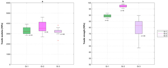
Figure 4.
Distribution of (a) tensile modulus and (b) tensile strength of groups 1 to 3.
However, pairwise comparisons of the tensile strength with the HSD-test of groups 1, 2, and 3 were possible when dividing group 3 into its respective subgroups 3.1 to 3.8 (Figure 5). This test implied that the tensile strength of all subgroups of group 3 except for 3.8 have significant differences from groups 1 and 2. Furthermore, the subgroups 3.5 and 3.6 also differ significantly from the rest of the subgroups of group 3. Figure 6 shows the 3D-printed parts of subgroup 3.1 before and after tensile test.
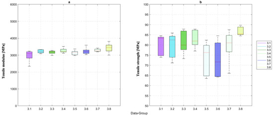
Figure 5.
The (a) tensile modulus and (b) tensile strength of PEEK printed samples of all subgroups of group 3.
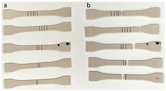
Figure 6.
(a) The 3D-printed samples of subgroup 3.1; (b) fractured samples after tensile test.
The highest and lowest tensile modulus values were observed with 3815.41 MPa and 3227.22 MPa, respectively. In contrast, the difference between the means of the eight groups’ tensile modulus was insignificant (p-value = 0.14).
3.3. Effect of Printing Position on Mechanical Properties
As illustrated in Figure 7, the bottom and top samples of groups 4 to 8 showed no significant differences among their means for the tensile modulus (bottom: p-value = 0.19, top: p-value = 0.2). This indicated that the position of the part in the build room had no influence on its performance and repeatability in terms of mechanics.
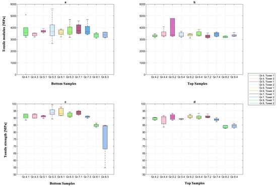
Figure 7.
Tensile modulus of the (a) bottom samples and (b) top samples as well as the tensile strength of the (c) bottom and the (d) top samples of groups 4–8.
Additionally, the Kruskal–Wallis test implied that the differences in the tensile strength between the bottom and top samples did not differ significantly (p-value = 0.096).
Further consideration of the differences was taken with an lmer test. The results showed that the tensile strength did not change significantly when the towers were taken as random effects (p-value = 0.124).
In addition, the differences between the top and bottom samples of each side of the pentagon towers did not show any significant differences (p-value = 0.26). Considering bottom and top samples of groups 4 to 8, two groups showed wider distribution of tensile modulus in bottom samples but were not significant (Figure 8). It showed that the height in Z-direction did not influence the reproducibility of the printing process.
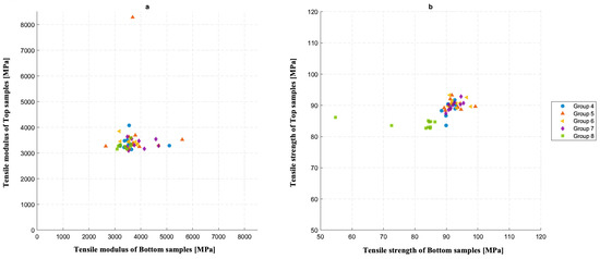
Figure 8.
Distribution of (a) tensile modulus and (b) tensile strength between the bottom and top samples.
An overall t-test, based on an lmer-model that checked whether the z-positions of the bottom and top samples influenced the tensile modulus with the respective towers’ placement, showed that the overall means of the top and bottom measurements did not differ significantly (p-value = 0.315).
The differences between top and bottom samples were also considered with a separate lmer test with only the towers as random effects. The differences showed no effect on the tensile modulus (p-value = 0.34).
Figure 9 shows the light microscopy and scanning electron microscope (SEM) images of fracture sites in one of the samples of group #4.1 after tensile testing.
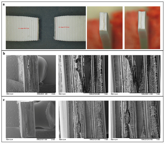
Figure 9.
Visualization of both fracture sites of a sample using (a) light microscopy and (b,c) SEM.
4. Discussion
The effects of different printing parameters—such as the orientation and position of the object top/bottom in different lateral positions—on the mechanical properties of PEEK printed samples using the MEX method were investigated in the current study. Other printing properties, such as nozzle diameter, filament, the temperature of the nozzle, build chamber, and plate, were kept constant [22,31,41,42,43].
According to the study of Basgul et al. [10], only one sample per build was printed. Therefore, the cooling time of a layer was decreased compared to printing more samples per platform, and the interlayer adhesion was improved, which would significantly affect ultimate strength [10].
Controlling the extruded line width in 3D printing PEEK biomaterial using the MEX method is an essential part of meeting commercial manufacturing requirements [22]. Maintaining uniform layers causes homogenous contact areas between the layers with fewer pores and cracks, which leads to better mechanical properties and lower surface roughness, as the main factor of final quality [22,41]. Nozzle size and the temperatures of the nozzle, bed, and chamber, which were kept constant in this study, are some factors that could affect the line width in the 3D printing process of PEEK biomaterial using the MEX method [22,31,41,42,43].
According to the study of Baek et al. [22], defining specific temperature parameters in the manufacturing of PEEK is very important as they directly affect mechanical properties, printing quality, and reliability. In another study by Wang et al. [44], it was mentioned that a higher nozzle temperature could facilitate filling voids and pores, as it leads to better fluidity of PEEK filament. Other studies revealed thermal degradation and increasing instability in the fabrication of PEEK 3D objects when PEEK filaments were printed at higher printing temperature. While higher printing temperatures led to lower viscosity and broader line width, the limitations for increasing temperature should be considered [22,34,43].
For these reasons, we fixed the nozzle size, and likewise fixed the temperature of the nozzle, chamber, and bed, in order to decrease instability in the printing process. The laminar airflow in the 3D printer also helped us to maintain homogeneous temperature distribution during the printing process [37], unlike the results reported in a previous study [45].
4.1. Effect of Printing Orientation on Mechanical Properties
Among different parameters, the printing orientation affects the mechanical performance of PEEK [29,41,46]. Zheng et al. [3] investigated the influence of printing orientation on the mechanical properties of PEEK/HA composite scaffolds fabricated via MEX 3D printing technology. For the mechanical testing, scaffolds were compressed parallel and perpendicular to the printing orientation. They concluded that samples represented higher Young’s modulus and lower compressive strength along the Z printing orientation [3]. The results of this study were not comparable to ours, as the samples were built not only with PEEK; HA was also included. Fabricated samples were also cubes with different pore sizes and underwent compression testing. In contrast, our samples were printed with a theoretic infill percentage of 100% in dog bone shape and underwent tensile testing.
Arif et al. [29] investigated PEEK samples printed in different orientations via MEX technology. They concluded that vertically printed samples had a poorer mechanical performance [29]. Cicala et al. [47] also mentioned that they had the lowest print void and best mechanical performance in horizontally printed samples out of PEEK material, which were dried for 48 h at 140 °C before printing. Even though the drying parameters of PEEK filaments were not similar to our study, results of mechanical test were in accordance with the results of our study, as we had no fractures in groups 1 and 2, with maximum tensile strengths of 91.613 MPa and 101.82 MPa, respectively; fractures were seen in group 3 with a tensile strength of 89.748 MPa.
The effect of the printing path on the mechanical properties of 3D-printed PEEK was also investigated by Zheng et al. [48], in a study which presented similar results to ours. They mentioned that printed samples along horizontal 0° exhibited the best mechanical properties and showed plastic deformation during tensile testing, which was loaded parallel to the printing orientation. Samples printed in this orientation did not completely rebond themselves, which may have affected the mechanical strength. Other samples printed in two different orientation paths, including horizontal 90° and vertical 90°, were loaded perpendicular to the printing orientation. They showed flat fracture morphology, which may have shown tearing at the interlayer interface [48]. Some other studies also reported that the orientation of printing had an essential impact on the tensile performance of 3D-printed PEEK samples. Thus, by printing in the horizontal orientation, we could achieve near bulk mechanical properties [9,29,46,49,50,51].
In the current study, pairwise comparisons of the tensile strength values of subgroups 3.1 to 3.8 showed a significant difference between subgroups 3.6 and 3.8; the means of the tensile modulus in groups 1, 2, and 3 were not significantly different (p-value = 0.063). This implied that the elastic behavior was the same, but differing durability could be seen due to voids generated during the milling process of creating dog bones out of printed towers or voids between layers during the printing process.
4.2. Effect of Printing Position on Mechanical Properties
We concluded that the position of printed parts, considering five different lateral positions and top/bottom positions, had no direct effect on mechanical properties such as tensile strength and tensile modulus of the PEEK printed parts at the point-of-care.
Basgul et al. [52] determined the interlayer strength of PEEK layers when 3D printed and mentioned that the dominant temperature settings in layer healing were nozzle, then build plate, and chamber, respectively. They concluded that the degree of healing increased linearly from the lower layers, which were closer to the build plate, to the upper layers. They also dried the filaments at 120 °C for four hours prior to printing, which could affect the reported results [52]. In accordance with another study by Basgul et al. [10], a single print job per build, a bigger nozzle, and a smaller build volume of the printer were associated with a higher ultimate load. It was mentioned that, in printing a single print job per build instead of two, the layers were laid over each other directly and the cooling time was shorter. A bigger nozzle diameter also resulted in less porosity and higher layer thickness which cooled more slowly than the volume of an extruded line through a smaller nozzle diameter. Additionally, 3D printers with smaller build volumes could preserve heat better than 3D printers with bigger build volumes. In their study, the values of PEEK filament drying, which can influence the properties of printed parts, was 60 °C for at least 12 h prior to printing [10]. It should also be noted that setting the temperature of the nozzle, bed, and chamber is very crucial, as it should be low enough to allow further layer building and high enough to reach the maximum interlayer strength [34,52,53,54,55,56] and avoiding delamination between individual deposition tracks (Figure 9).
These results were not in accordance with the results of our study, which may be due to the different methodology or laminar flow-altered cooling rate. However, we had the same nozzle diameter and 3D printer, and all samples were printed at a number of one per build.
5. Conclusions
- This is the first study, to our knowledge, to systematically investigate the mechanical and dimensional characteristics of MEX-printed PEEK samples printed at the point-of-care. The samples were printed in several orientations and at various positions spread across the entire build chamber and an assessment strategy was developed to study the influence of the printing parameters on the mechanical and dimensional accuracy attributes of the printed samples. Mechanical strengths of the MEX-printed PEEK samples were evaluated by tensile tests. In contrast to previous studies, the non-thermal printing parameters were chosen as an independent factor throughout the experiments. Based on our findings, the following conclusions have been drawn from this study: the tensile strength of the MEX-printed PEEK samples was in the range of 89.748–101.82 MPa, while the tensile modulus values were in between 3227.22 and 3815.41 MPa, respectively.
- The tensile tests showed that printing in XY and XZ orientations had no significant influence on the mechanical properties of printed parts. In addition, altering the position of the objects/test samples and the height of printing in the Z-direction did not influence the mechanical strength of PEEK-printed parts.
- The dimensional attributes and reliability of printing were also quantified and reported to be under 0.2 mm deviations.
Up until now, there has been no study for testing the physical attributes of MEX 3D-printed outputs, specifically for mechanical strength and dimensional accuracy attributes printed at the point-of-care. We believe that the approach and findings presented in this study are an important step toward establishing a framework for developing standardized tests for understanding these relevant characteristics prior to fabricating PEEK PSIs at the point-of-care.
Author Contributions
Conceptualization, P.Z. (Paridokht Zarean), P.M., P.Z. (Parichehr Zarean), D.S., M.d.W., F.M.T. and N.S.; methodology, P.Z. (Paridokht Zarean), P.M., P.Z. (Parichehr Zarean), D.S., M.d.W., F.M.T. and N.S.; software, P.Z. (Paridokht Zarean), P.M., P.Z. (Parichehr Zarean), D.S., M.d.W., F.M.T. and N.S.; validation, P.Z. (Paridokht Zarean), P.M., P.Z. (Parichehr Zarean), D.S., M.d.W., F.M.T. and N.S.; formal analysis, P.Z. (Paridokht Zarean), P.M., P.Z. (Parichehr Zarean), D.S. and M.d.W.; investigation, P.Z. (Paridokht Zarean), P.M., P.Z. (Parichehr Zarean), D.S., M.d.W., F.M.T. and N.S.; resources, D.S., M.d.W. and F.M.T.; data curation, P.Z. (Paridokht Zarean), P.M., P.Z. (Parichehr Zarean), D.S., M.d.W., F.M.T. and N.S.; writing—original draft preparation, P.Z. (Paridokht Zarean) and P.Z. (Parichehr Zarean); writing—review and editing, P.Z. (Paridokht Zarean), P.M., P.Z. (Parichehr Zarean), D.S., M.d.W., F.M.T. and N.S.; visualization, P.Z. (Paridokht Zarean), P.M. and P.Z. (Parichehr Zarean); supervision, D.S., M.d.W., F.M.T. and N.S.; project administration, D.S., M.d.W. and F.M.T. All authors have read and agreed to the published version of the manuscript.
Funding
This research received no external funding.
Institutional Review Board Statement
Not applicable.
Informed Consent Statement
Not applicable.
Data Availability Statement
Not applicable.
Acknowledgments
The authors thank Arnaud Bruyas and Stefan Leonhardt from Kumovis GmbH (Munich, Germany) for their support.
Conflicts of Interest
The authors declare no conflict of interest.
References
- Williams, D.F.; McNamara, A.; Turner, R.M. Potential of polyetheretherketone (PEEK) and carbon-fibre-reinforced PEEK in medical applications. J. Mater. Sci. Lett. 1987, 6, 188–190. [Google Scholar] [CrossRef]
- Skinner, H.B. Composite technology for total hip arthroplasty. Clin. Orthop. Relat. Res. 1988, 235, 224–236. [Google Scholar] [CrossRef]
- Zheng, J.; Zhao, H.; Dong., E.; Kang., J.; Liu, C.; Sun, C.; Li, D.; Wang, L. Additively-manufactured PEEK/HA porous scaffolds with highly-controllable mechanical properties and excellent biocompatibility. Mater. Sci. Eng. C Mater. Biol. Appl. 2021, 128, 112333. [Google Scholar] [CrossRef]
- Verma, S.; Sharma, N.; Kango, S.; Sharma, S. Developments of PEEK (Polyetheretherketone) as a biomedical material: A focused review. Eur. Polym. J. 2021, 147, 110295. [Google Scholar] [CrossRef]
- Zanjanijam, A.R.; Major, I.; Lyons, J.G.; Lafont, U.; Devine, D.M. Fused Filament Fabrication of PEEK: A Review of Process-Structure-Property Relationships. Polymers 2020, 12, 1665. [Google Scholar] [CrossRef]
- May, R. Polyetheretherketones. In Encyclopedia of Polymer Science and Engineering; Mark, H.F., Bikales, N.M., Overberger, C.G., Menges, G., Kroschiwitz, J.I., Eds.; John Wiley and Sons: New York, NY, USA, 1988; pp. 313–320. [Google Scholar]
- Green, S.M.; Schlegel, J. A polyaryletherketone biomaterial for use in medical implant applications. In Proceedings of the Polymers for the Medical Industry, Brussels, Belgium, 14–15 May 2001; pp. 1–7. [Google Scholar]
- Kurtz, S.M. PEEK Biomaterials Handbook; William Andrew: Norwich, NY, USA, 2019. [Google Scholar] [CrossRef]
- Gao, S.; Liu, R.; Xin, H.; Liang, H.; Wang, Y.; Jia, J. The Surface Characteristics, Microstructure and Mechanical Properties of PEEK Printed by Fused Deposition Modeling with Different Raster Angles. Polymers 2021, 14, 77. [Google Scholar] [CrossRef]
- Basgul, C.; MacDonald, D.W.; Siskey, R.; Kurtz, S.M. Thermal Localization Improves the Interlayer Adhesion and Structural Integrity of 3D printed PEEK Lumbar Spinal Cages. Materialia 2020, 10, 100650. [Google Scholar] [CrossRef]
- Dua, R.; Rashad, Z.; Spears, J.; Dunn, G.; Maxwell, M. Applications of 3D-Printed PEEK via Fused Filament Fabrication: A Systematic Review. Polymers 2021, 13, 4046. [Google Scholar] [CrossRef]
- Chia, H.N.; Wu, B.M. Recent advances in 3D printing of biomaterials. J. Biol. Eng. 2015, 9, 4. [Google Scholar] [CrossRef]
- Melchels, F.P.; Feijen, J.; Grijpma, D.W. A review on stereolithography and its applications in biomedical engineering. Biomaterials 2010, 31, 6121–6130. [Google Scholar] [CrossRef]
- Gibson, I.; Shi, D. Material properties and fabrication parameters in selective laser sintering process. Rapid Prototyp. J. 1997, 3, 129–136. [Google Scholar] [CrossRef]
- Stansbury, J.W.; Idacavage, M.J. 3D printing with polymers: Challenges among expanding options and opportunities. Dent. Mater. 2016, 32, 54–64. [Google Scholar] [CrossRef]
- Kruth, J.P.; Wang, X.; Laoui, T.; Froyen, L. Lasers and materials in selective laser sintering. Assem. Autom. 2003, 23, 357–371. [Google Scholar] [CrossRef]
- Turner, B.N.; Gold, S.A. A review of melt extrusion additive manufacturing processes: II. Materials, dimensional accuracy, and surface roughness. Rapid Prototyp. J. 2015, 21, 250–261. [Google Scholar] [CrossRef]
- Guo, N.; Leu, M.C. Additive manufacturing: Technology, applications and research needs. Front. Mech. Eng. 2013, 8, 215–243. [Google Scholar] [CrossRef]
- Frazier, W.E. Metal Additive Manufacturing: A Review. J. Mater. Eng. Perform. 2014, 23, 1917–1928. [Google Scholar] [CrossRef]
- Sharma, N.; Aghlmandi, S.; Dalcanale, F.; Seiler, D.; Zeilhofer, H.-F.; Honigmann, P.; Thieringer, F.M. Quantitative Assessment of Point-of-Care 3D-Printed Patient-Specific Polyetheretherketone (PEEK) Cranial Implants. Int. J. Mol. Sci. 2021, 22, 8521. [Google Scholar] [CrossRef]
- Sharma, N.; Honigmann, P.; Cao, S.; Thieringer, F. Dimensional characteristics of FDM 3D printed PEEK implant for craniofacial reconstructions. Trans. Addit. Manuf. Meets Med. 2020, 2, 011. [Google Scholar] [CrossRef]
- Baek, I.; Kwon, O.; Lim, C.M.; Park, K.Y.; Bae, C.J. 3D PEEK Objects Fabricated by Fused Filament Fabrication(FFF). Materials 2022, 15, 898. [Google Scholar] [CrossRef]
- Oladapo, B.I.; Zahedi, S.A.; Ismail, S.O.; Omigbodun, F.T.; Bowoto, O.K.; Olawumi, M.A.; Muhammad, M.A. 3D printing of PEEK–cHAp scaffold for medical bone implant. Bio-Des. Manuf. 2020, 4, 44–59. [Google Scholar] [CrossRef]
- Sun, Q.; Rizvi, G.M.; Bellehumeur, C.T.; Gu, P. Effect of processing conditions on the bonding quality of FDM polymer filaments. Rapid Prototyp. J. 2008, 14, 72–80. [Google Scholar] [CrossRef]
- Thomas, J.; Rodriguez, J. Modeling the fracture strength between fused-deposition extruded roads. In Proceedings of the Solid Freeform Fabrication Symposium Proceeding, Austin, TX, USA, 8–10 August 2000; pp. 16–23. [Google Scholar]
- Drummer, D.; Cifuentes-Cuéllar, S.; Rietzel, D. Suitability of PLA/TCP for fused deposition modeling. Rapid Prototyp. J. 2012, 18, 500–507. [Google Scholar] [CrossRef]
- Xinhua, L.; Shengpeng, L.; Zhou, L.; Xianhua, Z.; Xiaohu, C.; Zhongbin, W. An investigation on distortion of PLA thin-plate part in the FDM process. Int. J. Adv. Manuf. Technol. 2015, 79, 1117–1126. [Google Scholar] [CrossRef]
- Zhang, Y.; Chou, Y.K. Three-dimensional finite element analysis simulations of the fused deposition modelling process. Proc. Inst. Mech. Eng. B J. Eng. Manuf. 2006, 220, 1663–1671. [Google Scholar] [CrossRef]
- Arif, M.F.; Kumar, S.; Varadarajan, K.M.; Cantwell, W.J. Performance of biocompatible PEEK processed by fused deposition additive manufacturing. Mater. Des. 2018, 146, 249–259. [Google Scholar] [CrossRef]
- Li, H.; Liu, Z.; Gu, J.; Wang, D.; Qu, C. Preparation of high performance adhesives matrix based on epoxy resin modified by bis-hydroxy terminated polyphenylene oxide. J. Adhes. Sci. Technol. 2018, 32, 1224–1238. [Google Scholar] [CrossRef]
- Hu, B.; Duan, X.; Xing, Z.; Xu, Z.; Du, C.; Zhou, H.; Chen, R.; Shan, B. Improved design of fused deposition modeling equipment for 3D printing of high-performance PEEK parts. Mech. Mater. 2019, 137, 103139. [Google Scholar] [CrossRef]
- Rinaldi, M.; Cecchini, F.; Pigliaru, L.; Ghidini, T.; Lumaca, F.; Nanni, F. Additive Manufacturing of Polyether Ether Ketone (PEEK) for Space Applications: A Nanosat Polymeric Structure. Polymers 2020, 13, 11. [Google Scholar] [CrossRef]
- Hoskins, T.J.; Dearn, K.D.; Kukureka, S.N. Mechanical performance of PEEK produced by additive manufacturing. Polym. Test. 2018, 70, 511–519. [Google Scholar] [CrossRef]
- Yang, C.; Tian, X.; Li, D.; Cao, Y.; Zhao, F.; Shi, C. Influence of thermal processing conditions in 3D printing on the crystallinity and mechanical properties of PEEK material. J. Mater. Process. Technol. 2017, 248, 1–7. [Google Scholar] [CrossRef]
- El Magri, A.; El Mabrouk, K.; Vaudreuil, S.; Chibane, H.; Touhami, M.E. Optimization of printing parameters for improvement of mechanical and thermal performances of 3D printed poly(ether ether ketone) parts. J. Appl. Polym. Sci. 2020, 137, e49087. [Google Scholar] [CrossRef]
- Parthasarathy, J. 3D modeling, custom implants and its future perspectives in craniofacial surgery. Ann. Maxillofac. Surg. 2014, 4, 9–18. [Google Scholar] [CrossRef] [PubMed]
- Kumovis. A 3D System Company. Available online: https://kumovis.com/3d-printer/ (accessed on 3 November 2022).
- Davies, R.; Yi, N.; McCutchion, P.; Ghita, O. Mechanical property variance amongst vertical fused filament fabricated specimens via four different printing methods. Polym. Int. 2021, 70, 1073–1079. [Google Scholar] [CrossRef]
- Wang, Y.; Lee, K. 3D-printed semi-soft mechanisms inspired by origami twisted tower. In Proceedings of the 2017 NASA/ESA Conference on Adaptive Hardware and Systems (AHS), Pasadena, CA, USA, 24–27 July 2017; pp. 161–166. [Google Scholar] [CrossRef]
- Schönhoff, L.M.; Mayinger, F.; Eichberger, M.; Reznikova, E.; Stawarczyk, B. 3D printing of dental restorations: Mechanical properties of thermoplastic polymer materials. J. Mech. Behav. Biomed. Mater. 2021, 119, 104544. [Google Scholar] [CrossRef] [PubMed]
- Ding, S.; Zou, B.; Wang, P.; Ding, H. Effects of nozzle temperature and building orientation on mechanical properties and microstructure of PEEK and PEI printed by 3D-FDM. Polym. Test. 2019, 78, 105948. [Google Scholar] [CrossRef]
- Kumar, N.; Jain, P.K.; Tandon, P.; Pandey, P.M. The effect of process parameters on tensile behavior of 3D printed flexible parts of ethylene vinyl acetate (EVA). J. Manuf. Process. 2018, 35, 317–326. [Google Scholar] [CrossRef]
- Wu, W.Z.; Geng, P.; Zhao, J.; Zhang, Y.; Rosen, D.W.; Zhang, H.B. Manufacture and thermal deformation analysis of semicrystalline polymer polyether ether ketone by 3D printing. Mater. Res. Innov. 2014, 18, S5-12–S5-16. [Google Scholar] [CrossRef]
- Wang, P.; Zou, B.; Xiao, H.; Ding, S.; Huang, C. Effects of printing parameters of fused deposition modeling on mechanical properties, surface quality, and microstructure of PEEK. J. Mater. Process. Technol. 2019, 271, 62–74. [Google Scholar] [CrossRef]
- Sharma, N.; Aghlmandi, S.; Cao, S.; Kunz, C.; Honigmann, P.; Thieringer, F.M. Quality Characteristics and Clinical Relevance of In-House 3D-Printed Customized Polyetheretherketone (PEEK) Implants for Craniofacial Reconstruction. J. Clin. Med. 2020, 9, 2818. [Google Scholar] [CrossRef]
- Rinaldia, M.; Ghidinic, T.; Cecchinia, F.; Brandaoc, A.; Nanni, F. Additive layer manufacturing of poly (ether ether ketone) via FDM. Compos. B Eng. 2018, 145, 162–172. [Google Scholar] [CrossRef]
- Cicala, G.; Latteri, A.; Del Curto, B.; Lo Russo, A.; Recca, G.; Farè, S. Engineering Thermoplastics for Additive Manufacturing: A Critical Perspective with Experimental Evidence to Support Functional Applications. J. Appl. Biomater. Funct. Mater. 2017, 15, 10–18. [Google Scholar] [CrossRef] [PubMed]
- Zheng, J.; Kang, J.; Sun, C.; Yang, C.; Wang, L.; Li, D. Effects of printing path and material components on mechanical properties of 3D-printed polyether-ether-ketone/hydroxyapatite composites. J. Mech. Behav. Biomed. Mater. 2021, 118, 104475. [Google Scholar] [CrossRef] [PubMed]
- Rahman, K.M.; Letcher, T.; Reese, R. Mechanical properties of additively manufactured peek components using fused filament fabrication. In Proceedings of the ASME 2015 International Mechanical Engineering Congress and Exposition, Houston, TX, USA, 13–19 November 2015; American Society of Mechanical Engineers: New York, NY, USA, 2015; p. V02AT02A009. [Google Scholar]
- Sviridov, A.; Lopatina, I.; Kurganova, I. 3D-printed polyetheretherketone samples mechanical properties estimation. In IOP Conference Series: Materials Science and Engineering; IOP Publishing: Bristol, UK, 2019; Volume 589, p. 12021. [Google Scholar]
- Van Egmond, D.A. Properties of Poly(Ether Ether Ketone) as a High Performance Engineering Thermoplastic Processed by Fused Deposition Modelling, Internship Report; ESA-TECQEE-RP-004897; ESA: Paris, France, 2015. [Google Scholar]
- Basgul, C.; Thieringer, F.M.; Kurtz, S.M. Heat Transfer-Based Non-isothermal Healing Model for the Interfacial Bonding Strength of Fused Filament Fabricated Polyetheretherketone. Addit. Manuf. 2022, 46, 102097. [Google Scholar] [CrossRef]
- Wang, P.; Zou, B.; Ding, S. Modeling of surface roughness based on heat transfer considering diffusion among deposition filaments for FDM 3D printing heat- resistant resin. Appl. Therm. Eng. 2019, 161, 114064. [Google Scholar] [CrossRef]
- Zhang, J.; Wang, X.Z.; Yu, W.W.; Deng, Y.H. Numerical investigation of the influence of process conditions on the temperature variation in fused deposition modeling. Mater. Des. 2017, 130, 59–68. [Google Scholar] [CrossRef]
- Han, X.; Yang, D.; Yang, C.; Spintzyk, S.; Scheideler, L.; Li, P.; Li, D.; Geis-Gerstorfer, J.; Rupp, F. Carbon Fiber Reinforced PEEK Composites Based on 3D-Printing Technology for Orthopedic and Dental Applications. J. Clin. Med. 2019, 8, 240. [Google Scholar] [CrossRef] [PubMed]
- Basgul, C.; Spece, H.; Sharma, N.; Thieringer, F.M.; Kurtz, S.M. Structure, properties, and bioactivity of 3D printed PAEKs for implant applications: A systematic review. J. Biomed. Mater. Res. B Appl. Biomater. 2021, 109, 1924–1941. [Google Scholar] [CrossRef]


Disclaimer/Publisher’s Note: The statements, opinions and data contained in all publications are solely those of the individual author(s) and contributor(s) and not of MDPI and/or the editor(s). MDPI and/or the editor(s) disclaim responsibility for any injury to people or property resulting from any ideas, methods, instructions or products referred to in the content. |
© 2023 by the authors. Licensee MDPI, Basel, Switzerland. This article is an open access article distributed under the terms and conditions of the Creative Commons Attribution (CC BY) license (https://creativecommons.org/licenses/by/4.0/).