Article

Innovative Design of a Conductive Center Pole for an Active Thermal Insulation and Coring System in Deep Rock

1
School of Mechanical Engineering, Sichuan University, Chengdu 610065, China
2
State Key Laboratory of Hydraulics and Mountain River Engineering, College of Water Resource and Hydropower, Sichuan University, Chengdu 610065, China
3
College of Polymer Science and Engineering, Sichuan University, Chengdu 610065, China
4
College of Civil and Transportation Engineering, Shenzhen University, Shenzhen 518060, China
*
Author to whom correspondence should be addressed.
Appl. Sci. 2023, 13(3), 1242; https://doi.org/10.3390/app13031242
Submission received: 3 December 2022 / Revised: 4 January 2023 / Accepted: 14 January 2023 / Published: 17 January 2023
(This article belongs to the Special Issue Intelligent Manufacturing and Design for an Extreme Environment)

Abstract

:
Intelligent drilling technologies, such as downhole signal and power transmission, can be used to measure key downhole data and obtain thermal insulation cores. This technology is of great significance for the accurate assessment of deep oil and gas resources, the reconstruction of oil and gas resource extraction systems, and the realization of efficient, intelligent and safe resource extraction. In order to meet the needs of underground communication and power supply for active thermal insulation coring, a new type of conductive center pole was innovatively designed. Using the theory of innovation problem solving (TRIZ) and axiomatic design (AD) to analyze the functional requirements of the conductive central pole, establish and solve the original design matrix. Based on the axiomatic design theory, the non-coupling matrix is decoupled by using the TRIZ solving tool, and the key indicators of the design scheme that meet the independent axiom are evaluated. In view of the contradictions and conflicts, the TRIZ solution tool was continually used to solve, optimize and obtain a design scheme with a higher comprehensive evaluation. Thus, the self-adaptive non-winding connection and power conduction of the conductive center pole was realized. Finally, the strength of the newly designed center pole was checked, and a physical prototype was made. Pre-research experiments on its conductivity and electrothermal conversion efficiency were carried out under different simulation environments to verify its conductivity. It provides innovative solutions to related problems in the field of deep insulation coring and intelligent drilling and provides effective technical means for related needs.

1. Introduction

In 2021, British Petroleum (BP) released the 2021 World Energy Statistics Yearbook, in which non-renewable resources, such as oil, natural gas, and coal, accounted for an extremely high proportion of energy consumption around the world, reaching 83%. Even in recent years, the whole world has emphasized energy saving and emission reduction, and put forward related concepts such as “carbon neutrality” and “carbon peaking” to reduce carbon emissions [1,2] The consumption of renewable resources, such as wind and solar energy, has reached a historical peak and only accounts for 6% of the total consumption. Figure 1 shows the proportion of energy consumption in all continents and regions of the world [3].
Especially for developing countries, their dependence on non-renewable resources, such as oil and natural gas, is even more serious. For example, China’s consumption of non-renewable energy accounts for as high as 85%, which is higher than the world average. The proportion of energy consumption is shown in Figure 2. It can be seen that human beings are still highly dependent on the utilization of non-renewable resources, such as petrochemicals and oil and gas.
People’s high dependence on petrochemical resources has led to the gradual depletion of minerals and oil and gas resources in the shallow parts of the earth, and the exploitation of resources needs to continue to go to the deeper parts of the earth [4]. Efficient exploration and accurate assessment of deep oil and gas resources are crucial for their exploitation [5,6]. However, the existing deep resource mining work lacks consideration of the real physical and mechanical parameters and model basis of the core in the deep in situ environment, resulting in failure to achieve safe, efficient and economical deep resource mining and utilization [7]. Therefore, obtaining fidelity cores with deep in situ environmental conditions is of great significance to the exploration and evaluation of deep oil and gas resources [7].
At present, the research and application of fidelity core technology at home and abroad mostly belong to the category of holding pressure, and the fidelity of temperature is rarely involved [8,9]. However, changes in in situ sample temperature will also have a significant impact on rock porosity, permeability, and mechanical properties. The conventional coring technology lacks consideration of insulation, leading to serious deviations in results, affecting the preparation and evaluation of deep resources. It also helps researchers understand the microbial life in the deep subsurface of the Earth [10,11,12].
To find out the laws of the Earth’s oil and gas resource storage, it is necessary to overcome the influence of changes in the in situ sample temperature and other occurrences in the environment on the in situ properties of the rock during the coring process [13]. However, the extreme environment and complicated working conditions deep underground make it extremely difficult to achieve power and data transmission at the bottom of the hole, making it extremely difficult to achieve core temperature fidelity [9].
The research and development of key technologies and equipment for intelligent geological drilling at large depths is one of the necessary means to realize deep exploration [6] In this paper, aiming at the technical difficulties of in situ thermal insulation and coring in deep rocks, the mechanism and technical requirements for in situ thermal insulation and coring in deep rocks are analyzed, and innovative design methods are used to design and optimize the conductive center pole. Based on the independence axiom of axiomatic design and integrating TRIZ conflict resolution theory, the innovative design process of a downhole drilling conductive center rod is established. By analyzing the boundary conditions of the use environment, the design requirements of the conductive central rod are obtained, and the non-winding and effective contact power transmission of the underground conductive central rod is realized. In addition, it is not limited by the assembly position during the assembly of the central rod, and can be operated in the casing of the coring device, so as to realize the effective and stable connection of the power channel during the rotation of the central rod.
The conductive center pole will provide energy for the deep insulation system, establish deep underground information and power channels, realize intelligent and digital mining, and ensure the safety, speed and efficiency of the drilling process [14].

2. Related Works

At present, the international community only involves thermal insulation and coring in in situ low-temperature environments, such as combustible ice coring, while high-temperature thermal insulation and coring in deep hard rock is a blank in research. The core samplers with thermal insulation function include the pressure temperature core sampler (PTCS) designed by Japan Petroleum Corporation [15]. Multiple autoclave corer (MAC) and dynamic autoclave piston corer (DAPC) used in R.V.SONNE cruises developed by the German OMEGA project [16]. The pressure and temperature preservation system (PTPS) developed by China First Ocean Research Institute [17]. The hole bottom freezing core sampler (FCS) developed by Jilin University [18]. The insulation and pressure-maintaining sampler developed by Beijing Institute of Prospecting Engineering [19]. The gravity piston fidelity sampler of Zhejiang University [20] Changsha Mine Research Institute developed a deep-sea hard rock fidelity core remover [21]. The GW194-70BB thermal insulation pressure-maintaining coring tool and the coal-bed methane thermal insulation, pressure-maintaining and shape-preserving coring tool developed by the PetroChina Great Wall Drilling Engineering Technology Research Institute [22,23]. The heat preservation method of each core remover is shown in Table 1.
Except for the main types of core removers mentioned above, other core removers do not have the function of heat preservation. At present, most thermal insulation cores only use passive thermal insulation, and few use active thermal insulation. The most representative one is the pressure temperature core sampler developed by Japan, which has both active and passive heat preservation. Its structural principle is shown in Figure 3. The core remover mainly uses heat insulation materials and liquid nitrogen between the core lining pipe and the inner pipe to realize passive heat preservation. At the same time, a battery is used to drive the Peltier refrigeration sheet and cooperate with the low-temperature drilling fluid to remove the heat from the hot end, maintain high-efficiency thermoelectric conversion in the well, and realize active heat preservation. However, due to its complex structure, difficult processing, and high cost, its active insulation technology has only been tested indoors and has not been applied in engineering [15].
Since the in situ temperature of combustible ice is not much different from the ambient temperature, the use of passive heat preservation and pressure-maintaining coring technology can achieve combustible ice acquisition [24]. However, for deep hard rock, the in situ temperature is as high as hundreds of degrees Celsius, which is very different from the ground environment temperature. The heat loss during the coring process is serious, so it is necessary to take active heat preservation for real-time heat compensation to maintain the in situ temperature of the core.
Underground power supply and signal transmission technology are the prerequisites for realizing active thermal insulation and coring, but this is still a difficult problem internationally [25]. At present, most of the downhole signal and data transmission are realized through the drilling fluid pulse transmission method, electromagnetic wave transmission method, acoustic wave transmission method, optical fiber transmission method, and wired transmission method [26,27]. Downhole current transmission is realized by embedding cables inside the drill pipe, which greatly improves the reliability and power transmission capacity. This method was first proposed by Intelliserv Corporation of the United States, and is called smart drill pipe [28]. Wired drill pipe transmission technology includes the induction and wire butt method. As shown in Figure 4 and Figure 5, respectively [26,29].
However, the smart drill pipe is mainly for the measurement of the environmental parameters of the drill bit and the bottom hole and cannot conduct and supply electrical energy to the core remover in the drill pipe, let alone realize the temperature measurement and temperature control of the core. In addition, the commonly used wired connection methods in smart drill pipes also have problems such as inability to align electrodes, poor contact, and low connection reliability [26].
Referring to the design principles of smart drill pipes, and the use innovative design methods we designed and optimized the conductive structure of the center pole of the core remover to realize a self-adaptive non-winding connection and power conduction of the conductive center pole. Finally, a physical prototype was made for relevant experimental verification to meet the signal and power requirements for in situ insulation and coring operations of deep rocks.

3. Overdesign

3.1. The Position and Workflow of the Center Pole

When taking the core, the core remover is in the center of the drill pole. First, the drill bit and drill pole are used to drill holes. After reaching a specified depth, the core remover is lowered inside the drill pole. The mud pump provides power to the coring device to realize the deep in situ coring operation.
By arranging wires in the center pole, electrical energy is provided for the heating system at the bottom of the hole, realizing active insulation and core removal in situ. One of the main difficulties is to realize the electrical conduction at the connection position. The conductive process is shown in Figure 6.
With reference to the conduction mode of the smart drill pipe at the connection position, there are often problems such as unaligned electrodes, poor contact, and wire entanglement. Therefore, an innovative design is made for the conductive center pole in view of the above problems.

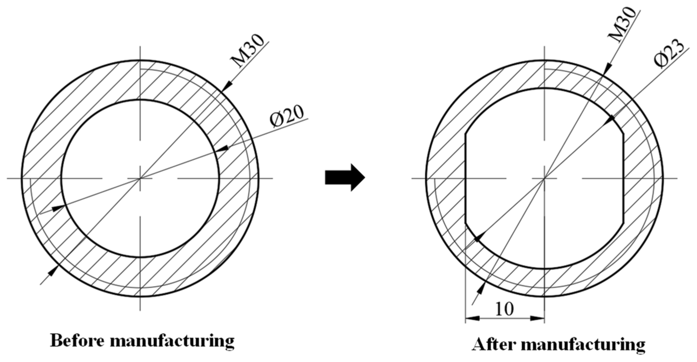
3.2. Center Pole Size and Assembly Requirements

The center pole is formed by connecting multiple sections of slender poles, and the interface at the connecting position is a circular ring with an outer diameter of 30 mm and an inner diameter of 20 mm, as shown in Figure 7. The center pole is small in size and compact in structure.
The center pole must strictly observe a certain assembly sequence during the assembly process, so assembly and wiring cannot be completed in advance. Additionally, it is required to realize the conduction of electrical energy at the same time after the screw connection of the central pole is completed.

4. Detailed Design of the Conductive Center Pole Based on the Innovative Design Method

4.1. Innovative Design Strategy and Process of the Conductive Center Pole

After clarifying the size and assembly requirements of the center pole, the innovative design method was used to carry out a detailed structural design according to its functional requirements. The TRIZ invention problem-solving theory was proposed by Rich Altshuller in 1964 [30,31]. The theory is composed of 39 engineering parameters and conflict matrices, 40 invention principles, four separation principles, and physical contradictions. It is believed that the essence of innovative and invention is the process of resolving contradictions [32,33].
Technical and physical conflict are the main research contents of the TRIZ theory. When we want to improve one feature in the technical system and cause another feature in the system to deteriorate, it is a technical conflict. When there are opposite requirements for a certain feature of a system, it is a physical conflict. To solve a technical conflict, the improved and deteriorated engineering parameters are defined with 39 technical parameters, and the invention principle of resolving the conflict is found in the classic conflict matrix, as shown in Figure 8. When there is a physical conflict in the technical system, four separation principles (space separation, time separation, separation of the whole and its parts, and conditional separation) and 40 corresponding invention principles are mainly used to solve the problem, as shown in Table 2.
Axiomatic design is a design decision method proposed by Professor Nam P. Suh of the Massachusetts Institute of Technology in 1990 [34,35]. Axiomatic design divides product design into the user domain { C A s } , functional domain {FRs}, physical domain {DPs}, and process domain {PVs}, and each domain can be represented by matrix mapping. Product design mainly refers to the process of mapping and solving the functional domain {FRs} and physical domain {DPs} of the designed product [36]. Nam Suh used mathematics to formalize his work in axiomatic design. The following equation articulates any solution to a given design problem.
{ F R } = [ A ] { D P }
Among them, [A] is the design matrix, which represents the relationship between the functional requirements and design parameters. When the design matrix [A] is a diagonal matrix or a triangular matrix, the elements in { F R } are independent from each other to meet the product design requirements, which is also called the independence axiom [37].
The specialty of axiomatic design lies in the systematicness of overall design and process decomposition, which can provide designers with logical and rational thinking methods and tools. TRIZ’s specialty lies in its technical innovation and the localization of conflict resolution. Based on the discussion of design theory and TRIZ theory, the technical process of the product design is formed according to the independence axiom of axiomatic design and the integration of TRIZ’s conflict resolution principle.
We analyzed the functional requirements of the conductive center pole, established the functional requirement vector { F R } , used the TRIZ solution tool to perform preliminary solutions, and obtained the original design matrix [A]. Then, we used the conflict matrix and object field analysis method in TRIZ to solve and optimize the contradictions and problems in the design [38,39]. Finally, a comprehensive evaluation was made from six aspects: “structural design”, “installation and assembly”, “material properties”, “independence”, “functionality”, and “manufacturability” to obtain comprehensive selection solutions and generate the corresponding design schemes. Then, we evaluated the generated scheme according to the initial functional requirements, and obtained the final feasible design scheme.
The innovative design process of the conductive center pole is shown in Figure 9.

4.2. Analysis of the Functional Requirements of the Conductive Center Pole

Thermal insulation in the deeper parts of the ground has high requirements for the design of power and signal transmission mechanisms. The conductive function is integrated into the center pole, and the conductive module is required to be connected and screwed with the center pole to complete the conduction of electricity.
The structure and performance design of the new conductive center pole needs to meet the following requirements:
  • The conductive module can realize the alignment of the positive and negative electrodes after the center pole is rotated and docked.
  • The conductive module can realize the contact between the positive and negative electrodes after the center pole is rotated and connected.
  • Avoid entanglement of the wire during the screwing process of the center pole.
  • The whole operation process meets the requirements of insulation and 150 °C temperature resistance.
A vector of the functional requirements is established, as follows:
[ F R 1 F R 2 F R 3 F R 4 ] = { Align   the   electrodes   at   both   ends Electrode   contact   at   both   ends The   wire   is   not   entangled Insulation   and   high   temperature   resistance   ( 150   ° C ) }

4.3. Establishing the Design Parameter Vector and Design Matrix of the Conductive Center Pole

Solving the design parameter DP1: In order to ensure that the two poles of the conductive module can be accurately aligned after the center pole is screwed and docked, the corresponding position of the center pole can be marked after the center pole is screwed. Additionally, the electrode channel corresponding to the conductive module can be arranged at the marked position, and increase the probability of electrode alignment by increasing the contact area.
Solving the design parameter DP2: In order to ensure that the two poles of the conductive module can fully contact and achieve conduction after the center pole is screwed together, the length of the connecting thread of the center pole should be measured in advance, and the placement position of the conductive module in the center pole should be designed according to the distance after screwing.
Solving the design parameter DP3: In order to ensure that the wire is not twisted during the screwing and installation process of the center pole, an anti-rotation structure can be designed between the conductive module and the center pole to avoid the relative rotation of the conductive module and the center pole during the screwing process, which may cause the wire to be twisted.
Solving the design parameter DP4: To ensure the insulation and temperature resistance of the conductive module, high-temperature-resistant resin and conductive copper phase materials can be used. The high-temperature resin is small in size and difficult to machine, so must be manufactured by 3D printing.
The expression of the design parameter vector can be obtained as follows:
[ D P 1 D P 2 D P 3 D P 4 ] = { Mark   the   position   in   the   circumferential   direction   of   the   center   rod Measure   and   set   the   length   of   the   thread Design   anti - rotation   structure Use   high   temperature   resistant   resin }
Through the expression of the design parameter vector, the initial conceptual design diagram of the conductive center pole can be obtained, as shown in Figure 10.
Set the elements in the design matrix A to X. It can be seen from the mapping relationship between the functional requirement vector { F R } and the design parameter vector { D P } that the connection of the conductive module is related to the position of the center pole circumferential mark, the thread length, and the angle of the anti-rotation structure. Therefore, the design parameter DP1 is related to the design parameters DP2 and DP3, and the design parameter DP2 is related to the design parameter DP1 and DP3. The design matrix A is as follows:
A = { 1 1 1 0 1 1 1 0 0 0 1 0 0 0 0 1 }
In the design matrix A, 1 means that there is a correlation between the design parameters, and 0 means that there is no correlation between the design parameters. This matrix is a coupling matrix and does not satisfy the independence axiom design. The associated design needs to be optimized and decoupled to form a triangular or diagonal array that meets the design requirements.

4.4. Design Matrix Decoupling Based on TRIZ

To decouple the design matrix A for the conductive module structure of the center pole in Figure 10, the position and length of the center pole need to be calibrated after the center pole is tightened to ensure that the conductive module can be screwed together with the center pole to complete the alignment and contact of the electrodes. However, whether the conductive module can be conducted is related to the position of the electrode in the circumferential direction, the distance in the axial direction, and the relative position of the anti-rotation structure. It is necessary to ensure the alignment of the electrodes and to ensure that the electrodes are in full contact and are not affected by the angle of the anti-rotation structure, that is, to eliminate the influence of elements A12, A13, A21, and A23 in matrix A. Furthermore, the required effects or effects that need to be eliminated must be established according to functional requirements.
Ideally, to realize the conduction of the conductive module in the center pole, it is necessary for the conductive module to completely align its electrodes and ensure sufficient contact at the same time after the connection is completed. In order to avoid wire entanglement during the installation, an anti-rotation structure was designed to make the conductive module and the center pole move in-sync, remaining relatively static. However, the conductive modules in the two sections of the center pole move with the center pole, resulting in a relative rotation, which causes the electrodes of the two sections to move relative to each other, making it difficult to ensure alignment.
This problem is the alignment of the two conductive poles, which belongs to the physical conflict in TRIZ. When the two sides of the key subsystem conflict only appear on one side of a certain space, the space separation method can be used to resolve the physical conflict. Mann of the University of Bath in the United Kingdom proposed that there is a corresponding relationship between the separation principle for resolving physical conflicts and the invention principle for resolving technical conflicts. There are multiple invention principles corresponding to one separation principle, and more ideas for solving problems are provided [40]. The corresponding relationship is shown in Table 2.
The solution to spatial separation includes 10 principles of invention. To solve the problem of electrode alignment in the conductive module, the invention principle seven “nesting” and the invention principle 17 “space dimension change” can be used. “Nesting” refers to embedding an object in another object or allowing something to pass through the cavity of another object. “Space dimensionality change” refers to changing one-dimensional linear motion into two-dimensional plane motion or three-dimensional space motion. With the help of these two principles, and considering the rotational movement of the conductive module, the electrode can be designed as a combination of a ring and a dot. The dot-shaped electrode is placed in the center of the circular ring electrode, and the electrode at the other end is the dot-shaped electrode at the corresponding position, which avoids the problem that the two electrodes cannot be aligned due to the rotational movement. The structure before and after the improvement is shown in Figure 11.
This design ensures that when the center pole drives the conductive module to rotate, the electrodes at both ends can always be aligned in the circumferential direction and the center position and are not affected by the center rod’s circumferentially calibrated position and the angle of the anti-rotation structure. Therefore, A12 and A13 in the design matrix A can be eliminated, and the alignment before contact can also be satisfied, that is, A23 can also be eliminated. Matrix A is improved to matrix B, as shown below:
B = ( 1 0 0 0 1 1 0 0 0 0 1 0 0 0 0 1 )
However, whether the electrode can contact is still related to the circumferential calibration position of the center pole, that is, the angle of rotation of the center pole, so A21 is still 1. It can be judged by the independent axiom that the improved matrix B is still a coupling matrix, and the design scheme still needs to be improved. Since the contact of the conductive module is related to the screwing angle of the center pole and the thread wear condition, when the center pole is completely screwed, it may cause insufficient contact or excessive squeeze. The object–field model between the center pole and the conductive module can be established for analysis, as shown in Figure 12. S1 represents the conductive module, S2 represents the center pole, and F1 represents the electrical conduction.
Due to the insufficient contact or excessive squeezing of the conductive module, this object–field model belongs to the ineffective complete model and the harmful complete model. According to the general solution of the object–field model, the useful effect can be improved by adding another substance S3 and another field F2. Considering that the degree of electrode contact can be adjusted by itself, a spring that can provide a telescopic function is introduced as S3, and the elastic force field is F2. The improved object–field model of the conductive module is shown in Figure 13.
By adding a spring mechanism between the center pole and the conductive module, and introducing an elastic force field, the problem of insufficient or excessive contact between the conductive modules is solved.
The functional behavior structure diagram to realize the conductive function of the center pole can be obtained, as shown in Figure 14 [41].
By adding a spring mechanism between the center pole and the conductive module, the adaptive adjustment of the electrode contact is realized. The conductive center pole is shown in Figure 15. The space and positioning structure for placing the spring mechanism are designed inside the center pole, the spring is installed on the positioning structure, and the conductive module is placed on the spring. During the screwing process of the center pole, the two electrodes always remain aligned. A certain length of spring is selected to provide the initial pre-pressure to ensure contact, and after the screwing is completed, the position of the two electrodes is automatically adjusted by the compression spring to make them fully squeeze in contact without excessive squeezing, ensuring the safe conduction of electricity.
In this design, the contact of the electrode can be adjusted by a spring, and the contact of the electrode can be achieved even if the fixed-length thread and the circumferential position of the center pole are not set, that is, A21 can be 0. After design matrix B is improved, it becomes matrix C, as shown below.
C = ( 1 0 0 0 0 1 0 0 0 0 1 0 0 0 0 1 )
The design matrix C is a diagonal matrix, which satisfies the independence axiom design.

4.5. Optimized Design of the Conductive Center Pole

According to the design of the conductive center pole in Figure 15, the design of the conductive center pole can meet the basic installation and conductivity requirements. However, its “independence”, “functionality” and “installation and assembly” still need to be improved. In terms of “installation and assembly”, a spring mechanism has been added, and an elastic force field has been introduced, which can solve the situation of insufficient or excessive contact of the conductive module. However, the internal space requirement for the center pole has increased, and the increased spring mechanism reduces the overall assemblability. In terms of “independence” and “functionality”, although the electrode alignment and contact of the conductive module are not affected by the rotational angle of the center pole and the thread length, this structure has high requirements for the relative position between the two electrodes. Because the two electrodes are on the same conductive module, if one electrode comes into contact earlier than the other electrode, the first electrode in contact will push the conductive module to squeeze the spring, causing the conductive module to move as a whole, while the other electrode will not contact. The contact of the electrodes will form mutual interference. As shown in Figure 16.
In order to solve the problem of mutual interference of electrode contact, it is necessary for the two electrodes to have the ability to move and adjust independently, but the conductive module belongs to a hole with a fixed shape, and there is a physical conflict here. The division principle in the invention principle in Table 2. can be used to divide the electrodes so that they can be aligned and contacted, respectively. The preliminary segmentation is shown in Figure 17.
To optimize the “overall assemblability.” of the conductive module, it is necessary to simplify the shape of the spring and the conductive module to reduce the difficulty of assembly and avoid interference with the center pole. However, the internal complexity of the corresponding system will increase, and its manufacturability will also deteriorate.
In engineering design, one design parameter of the system is improved, while another parameter is aggravated, that is, technical conflict [30,31]. To solve the technical conflict, it is necessary to transform the actual problem into the conflict problem model. The relationship between the technical parameters and the invention principle is found through the conflict matrix table, and the final solution is obtained according to the invention principle.
Using the technical conflict resolution theory, the corresponding technical parameters and invention principles in the classic conflict matrix were found, as shown in Table 3.
To simplify the shape of the conductive module, while avoiding the deterioration of its manufacturability and system complexity, inventive principle 1 (segmentation: divide the object into mutually independent, detachable and installable parts) can be used as a solution. This solution integrated the spring structure into the conductive structure to make the overall shape more concise and easy to assemble, while retaining the expansion and contraction function of the spring. Even if the initial segmentation operation is performed, as shown in Figure 17, the relative position of the two electrodes in the axial direction cannot be guaranteed before the central rod is tightened, and they are prone to misalignment. So the segmentation operation in Table 3 needs to be performed again. This separation needs to maintain the shape of the conductive module, including the spring structure and can meet the independent adjustment of the two electrodes. The structure of the separated components is shown in Figure 18.
As shown in Figure 18, the four electrodes at both ends are separated in the axial direction so that they can move independently without interfering with each other. The insulating base 2 and the straight conductive copper 3 must be threaded together to form an independently movable electrode unit, as shown in Figure 18a. The ring-shaped insulating base 5 and the corresponding ring-shaped conductive structure 6 are assembled to form an independently movable electrode unit, as shown in Figure 18b. The insulating base 7 and the straight conductive copper 8 must be threaded together to form an electrode unit that can move independently, as shown in Figure 18c. The insulating base 9 and the straight conductive copper 10 must be threaded to form an electrode unit that can move independently, as shown in Figure 18d.
The spring structure is integrated with the conductive module to make it both functional and simple in appearance. The original conductive module structure is divided to form a split structure, and the spring and the four independently moving electrodes a, b, c, and d shown in Figure 18 are placed inside the conductive module. Additionally, the split and step structures are placed in the insulating seat to form an assembly fit to realize the limit and movement guidance. Finally, its function integration and appearance simplification are carried out. The simplified conductive structure and overall shape are shown in Figure 18e.
The final design of the conductive center pole is shown in Figure 19.
The electrode unit a and the electrode unit b are matched with each other, the electrode unit c and the electrode unit d are matched with each other, and the conduction and self-adaptive adjustment of the electrode are realized by a spring.
The optimized conductive center pole integrates the spring structure, solves the contact interference of the two electrodes, and optimizes its “installation and assembly”, “independence” and “functionality”.

4.6. Design Comprehensive Evaluation and Analysis

According to the functional requirements and the comprehensive solution from Figure 9. The overall design scheme was evaluated from six aspects: “structural design”, “installation and assembly”, “material properties”, “independence”, “functionality” and “manufacturability”.
The design schemes of the above three conductive center poles are summarized and evaluated through the analytic hierarchy process [42,43], as shown in Table 4. Scheme A is improved on the basis of the original scheme (Figure 10) by changing the electrode contact from surface contact to point contact, which solves the problem that the electrodes cannot be aligned when the conductive structure rotates with the central rod. Scheme B separates the conductive structure on the basis of Scheme A, and adds a spring structure at the middle electrode. The problem that the conductive structure in Scheme A is excessively squeezed and contacted after the central rod is rotated is solved. Scheme C is improved on the basis of Scheme B. The electrode is separated again, and the spring is integrated into the conductive structure, which increases the overall installation of the conductive structure.

5. Strength Check of the Conductive Center Pole

In order to assemble the conductive module, it is necessary to expand the hollow inside the center pole, which causes the pipe wall at the threaded part to be thinned. The cross-section of the threaded connection is shown in Figure 20.
Therefore, it is necessary to check the strength of the threaded connection structure of the center pole after processing and thinning to ensure that the center pole can complete the lifting of the core remover.
During the operation of the core remover, it is always in a vertical working state. After the core is completed, the center pole needs to vertically lift the corer with a weight of about 350 kg. The threaded connection strength when the central pole is subjected to an axial load, and the tensile strength of the structure at the weakest part of the central pole need to be identified and resolved [44].
The connection of the center pole adopts an M30 standard thread, the pitch P is 2 mm, and the minor diameter d1 of the thread is 27.835 mm. The center pole is made of 304 stainless steel, its yield strength ReL is 310 MPa, and its tensile strength Rm is 620 MPa. In the case of a static load, the safety factor SS of the bolt connection is taken as 4. To ensure the reliability of the threaded connection, it is required that the residual pre-tightening force of 1.3 times the working load is retained when the center pole is tensioned.
σ = 1.3 ( 1.3 F 0 + F 0 ) π 4 d 1 2 = 17.1   MPa
The allowable strength is:
[ σ ] = R eL S s = 77.5   MPa
The strength check value is far less than the allowable strength, and the strength of the threaded connection meets the needs of use.
The tensile strength of the thinned part of the center pole must be checked. The cross-sectional area of the threaded connection of the center pole is As, and the area of the hollow is Ad.
A s = π d 1 2 A d = 215.9   mm 2
σ = 1.3 F 0 + F 0 A s = 37.29   MPa
Taking the safety factor Ss as 4, the allowable tensile stress is [ σ s ] .
[ σ s ] = R m S s = 155   MPa
The tensile strength value is much smaller than the allowable tensile strength, which meets the operation requirements of the center pole pulling and lifting.

6. Experiments and Results

6.1. Continuity Performance Test

A physical prototype of the designed conductive center pole was made, as shown in Figure 21. Since it only needs to verify the action and conduction performance of the key structure of the conductive module, on the basis of retaining the key features and dimensions of the center pole, it has been reduced in the length direction. The lengths of the two test center poles are 200 mm and 133 mm, respectively, and the connection between the center poles is an annulus with a diameter of 20 mm and an M30 threaded connection.
The resistance of the connected conductive center pole was measured using a multimeter, as shown in Figure 22.
It was measured that one end of the connection resistance was 0.3 Ω, and the other end was 0 Ω, and its conduction performance was good. The electrothermal conversion efficiency of the center pole conductive module in actual use still needs further experimental verification.

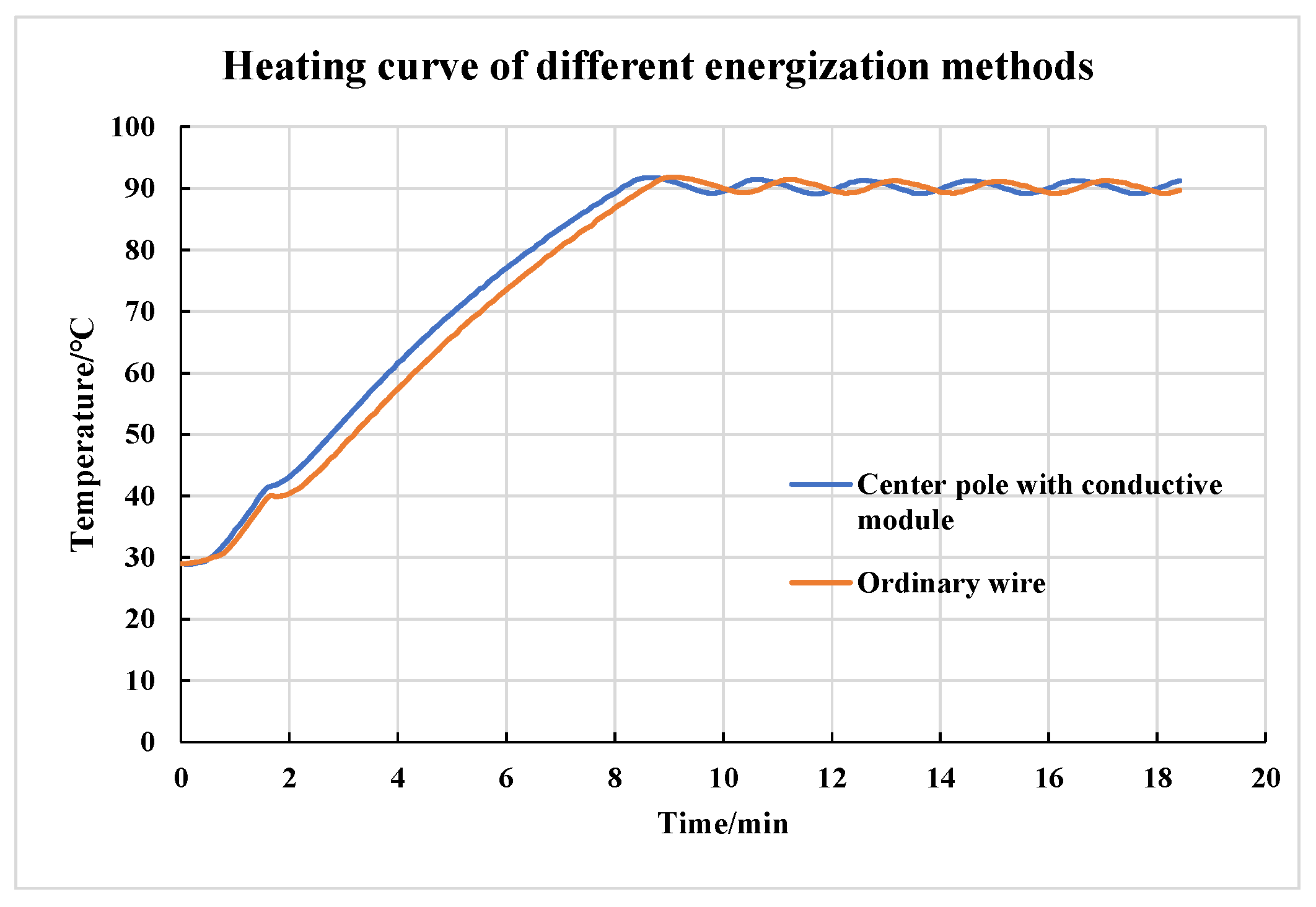
6.2. Heating Performance Test of the Conductive Center Pole at Room Temperature

A conductive center pole and a conventional wire were used to power the carbon nano-material heater and heat the thermal oil, respectively, to compare its electrothermal conversion efficiency. The experimental platform is shown in Figure 23.
Using a 12 V DC power supply to supply power to the load, 100 mL of thermal oil was heated with a heating target temperature of 90 °C, and kept at a constant temperature for 10 min after reaching the target temperature. The results of the experiment are shown in Figure 24. The thermal oil was heated to 90 °C through the conductive center pole and the conventional wire, which took 8 min and 8 min and 35 s, respectively.

6.3. Heating Performance Test of the Conductive Center Pole at High Temperatures

The oven was used to simulate an in situ high-temperature environment of 150 °C to verify the working performance of the conductive center pole in a high-temperature environment. The conductive center pole was placed in a high-temperature oven, and the rest of the connected electronic components were placed outside the oven to ensure normal operation. The principle of the experimental system is shown in Figure 25.
The physical experiment platform is shown in Figure 26.
The results of the high-temperature-resistance test of the conductive center pole are shown in Figure 27. Heating the same thermal oil to 90 °C took 2 min and 45 s longer in a high-temperature environment than at room temperature, taking 10 min and 45 s in total. On the one hand, it is considered that due to the increase in temperature, the resistance of the wires in the center pole increases, and the loss of power consumption increases. On the other hand, the uniformity of the temperature distribution of the thermal oil is poor, and the position of the temperature sensor has great influence on its readings, which ultimately makes the heating curve of the two environments different.

6.4. Long-Term Effectiveness and Stability Test of the Energy Supply Transmission and Signal Transmission of the Conductive Central Rod

In order to verify the long-term effectiveness and stability of the conductive central rod in the process of power and signal transmission, the long-term work and temperature and pressure signal transmission test experiments were added on the basis of the above experiments.
In the long-term energy supply stability test, the conductive central rod is used as the current-carrying middleware. The twisted conductive central rod is connected in series with the heating load, and the heating load is powered by a 0–30 V adjustable DC power supply. The heating medium is heat conduction oil, and the heating target temperature was set at 100 °C. When the target temperature was reached, the temperature was maintained by a paperless recorder and relay. The whole experiment process was set to maintain the temperature for more than 100 h. The experimental results are shown in Figure 28, which verify that the conductive central rod, as a current-carrying middleware, can stably supply power for a long time and meet the dynamic response when the voltage and current change.
In addition, the signal transmission performance of the conductive central rod was verified by experiments. First, the signal transmission of the PT100 temperature sensor was tested. The temperature sensor was connected in series with the conductive central rod, and the heat conducting oil was used as the object of temperature measurement. The different temperatures of the heat conducting oil at different times were measured and recorded. The experimental results are shown in Figure 29. The temperatures measured by the temperature sensor in series with the conductive central rod and the standard temperature sensor have a high consistency. Due to the different placement positions of the sensors, the measured temperatures have slight differences, but basically meet the engineering application requirements.
Later, the pressure sensor signal transmission was tested. The pressure sensor was connected in series with the conductive central rod, and connected with the hydraulic station for pressurization and pressure data acquisition. In the experiment, the hydraulic source pressure was raised from 0 MPa to 63 MPa within 200 s, and the pressure data collected by the test pressure sensor was compared with the standard pressure data of the hydraulic station. The experimental results are shown in Figure 30. The two pressure data have good consistency and can meet the engineering application requirements.
The signal transmission experiment of the temperature sensor and pressure sensor verified the stability and reliability of the conductive central rod as the signal-transmission middleware, which has certain application prospects in the field of deep in situ measurements.

7. Conclusions

In this paper, based on the requirements of the in situ insulation and coring of deep rocks, and based on energized smart drill pipe technology commonly used in the logging field, an innovative conductive center pole was developed. The conductive center pole meets the power supply and lifting strength requirements for the in situ insulation and coring of deep rocks. With a small size, high-reliability connection and self-adjustment function, it can realize the non-winding energization and communication between the center poles.
  • According to the requirements for the in situ insulation and coring of deep rocks and referring to the design of smart drill pipes in logging, the overall design of the conductive center pole is proposed.
  • The innovative design process of the conductive center pole is proposed, the functional requirements of the conductive center pole were analyzed, and the design matrix A was established and solved.
  • The TRIZ solving tool was used to obtain a preliminary design scheme, and to further optimize the scheme to obtain a scheme with a higher comprehensive evaluation.
  • The strength of the conductive center pole of the new structure was verified, and a physical prototype was made to conduct comparative experiments in a realistic environment to verify the feasibility of its function and structure.
  • In addition, the feasibility of its application in the field of energy supply and signal transmission was verified through long-term heating experiments and sensor data acquisition tests.
The conductive center pole technology proposed in this paper is of great significance for the realization of underground power supply and communication. The effectiveness of the integrated application and the design processes of the axiomatic and TRIZ design methods were verified. The preliminary research experiments were carried out in an ideal indoor environment. It performed well in the installation and resistance tests, and could realize a normal energy supply to the load under high-temperatures, which verified its characteristics of a non-winding and stable connection. It provides technical support for the accurate assessment of oil and gas resources and the realization of intelligent, efficient and safe digital drilling. It is also provides an innovative approach for the in situ insulation and coring of deep rocks. Follow-up work will continue to focus on experimental tests under high-temperature and high-pressure and practical engineering applications.

Author Contributions

Conceptualization, B.Y.; methodology, B.Y.; writing—original draft preparation, B.Y.; writing—review and editing, Z.H.; software, Z.H.; resources, J.Y.; investigation, Z.W.; data curation, C.L.; supervision, H.X.; funding acquisition H.X.; projection administration H.X. All authors have read and agreed to the published version of the manuscript.

Funding

This research was founded by the National Key R&D Program of China, grant number 2022YFB3706605, National Natural Science Foundation of China, grant number 52274133, National Natural Science Foundation of China, grant number 51827901.

Institutional Review Board Statement

Not applicable.

Informed Consent Statement

Not applicable.

Data Availability Statement

The data used to support the findings of this study cannot be shared.

Conflicts of Interest

The authors declare that they have no competing financial interests or personal relationships that could appear to have influenced the work reported in this paper.

References

  1. Lin, W.; Wu, J. Discussion on the roadmap of China’s energy transition framework under the goal of carbon neutrality. Price Theory Pract. 2021, 6, 9–12. [Google Scholar] [CrossRef]
  2. Xie, H.; Ren, S.; Xie, Y.; Jiao, X.M. Development opportunities of the coal industry towards the goal of carbon neutrality. J. China Coal Soc. 2021, 46, 2197–2211. [Google Scholar] [CrossRef]
  3. bp.com. Statistical Review of World Energy; Whitehouse Associates: London, UK, 2021; Available online: https://www.bp.com/en/global/corporate/energy-economics/statistical-review-of-world-energy.html (accessed on 21 June 2022).
  4. Xie, H.; Gao, F.; Ju, Y. Research and development of rock mechanics in deep ground engineering. Chin. J. Rock Mech. Eng. 2015, 34, 2161–2178. [Google Scholar] [CrossRef]
  5. Xie, H.; Gao, M.; Zhang, R.; Chen, L.; Liu, T.; Li, C.; Li, C.; He, Z. Study on concept and progress of in situ fidelity coring of deep rocks. Chin. J. Rock Mech. Eng. 2020, 39, 865–876. [Google Scholar] [CrossRef]
  6. Xue, Q.; Zhang, J. Advances in intelligent automatic drilling technologies and equipment. Explor. Eng. (Rock Soil Drill. Tunn.) 2020, 47, 9–14. [Google Scholar] [CrossRef]
  7. Xie, H.; Gao, F.; Ju, Y.; Gao, M.Z.; Zhang, R.; Gao, Y.N.; Liu, J.F.; Xie, L.Z. Quantitative definition and investigation of deep mining. J. China Coal Soc. 2015, 40, 1–10. [Google Scholar] [CrossRef]
  8. Li, C.; Xie, H.; Gao, M.; Chen, L.; Zhao, L.; Li, C.; Wu, N.; He, Z.; Li, J. Novel designs of pressure controllers to enhance the upper pressure limit for gas-hydrate-bearing sediment sampling. Energy 2021, 227, 120405. [Google Scholar] [CrossRef]
  9. Yu, B.; Zhao, W.; Chen, L.; Gao, M.; He, Z.; Wan, H. Innovative design of active insulation system for in-situ fidelity coring in deep strata. Chin. J. Eng. Des. 2020, 27, 407–415. [Google Scholar] [CrossRef]
  10. Kashefi, K.; Lovley Derek, R. Extending the Upper Temperature Limit for Life. Science 2003, 301, 934. [Google Scholar] [CrossRef]
  11. Borgonie, G.; García-Moyano, A.; Litthauer, D.; Bert, W.; Bester, A.; van Heerden, E.; Möller, C.; Erasmus, M.; Onstott, T.C. Nematoda from the terrestrial deep subsurface of South Africa. Nature 2011, 474, 79–82. [Google Scholar] [CrossRef]
  12. Teske, A.P. The deep subsurface biosphere is alive and well. Trends Microbiol. 2005, 13, 402–404. [Google Scholar] [CrossRef]
  13. Lupton, N.; Connell, L.D.; Heryanto, D.; Sander, R.; Camilleri, M.; Down, D.I.; Pan, Z. Enhancing biogenic methane generation in coalbed methane reservoirs—Core flooding experiments on coals at in-situ conditions. Int. J. Coal Geol. 2020, 219, 103377. [Google Scholar] [CrossRef]
  14. Yan, T.; Xu, R.; Liu, W.; Sun, W.; Hou, Z.; Shao, Y. Research and development of intelligent drilling technology in China. J. Northeast. Pet. Univ. 2020, 44, 15–21+6. [Google Scholar] [CrossRef]
  15. Abid, K.; Spagnoli, G.; Teodoriu, C.; Falcone, G. Review of pressure coring systems for offshore gas hydrates research. Underw. Technol. 2015, 33, 19–30. [Google Scholar] [CrossRef]
  16. Abegg, F.; Hohnberg, H.-J.; Pape, T.; Bohrmann, G.; Freitag, J. Development and application of pressure-core-sampling systems for the investigation of gas- and gas-hydrate-bearing sediments. Deep Sea Res. Part I 2008, 55, 1590–1599. [Google Scholar] [CrossRef]
  17. Zhu, H.Y.; Liu, Q.Y.; Wong, G.R.; Xiao, X.H.; Zhu, X.H.; Jiang, Z.L.; Zhang, D.Y. A Pressure and Temperature Preservation System for Gas-hydrate-bearing Sediments Sampler. Pet. Sci. Technol. 2013, 31, 652–662. [Google Scholar] [CrossRef]
  18. Wang, Y.; Guo, W.; Sun, Y.; Jia, R.; Liu, H.N.; Xue, J. The Development of Wire-line Sampling Drilling Tool for Gas Hydrates by Hole Bottom Freezing with Development of Wire-line Sampling Drilling Tool for Gas Hydrates by Hole Bottom Freezing with Liquid Nitrogen as Ex-ternal Cold Source. Drill. Eng. 2013, 40, 1–3. [Google Scholar] [CrossRef]
  19. Liu, X.; Zhao, Y.; Liu, H.; Ruan, H.; Chem, Y.; Shen, L.; Wu, H.; Liang, Q. Comparative Study on Sampling Tools for Insulation and Pressure-holding of Marine Gas Hydrate. Equip. Geotech. Eng. 2018, 19, 11–15. [Google Scholar] [CrossRef]
  20. Li, S.; Cheng, Y.; Qin, H. Development of pressure piston corer for exploring natural gas hydrates. J. Zhejiang Univ. (Eng. Sci.) 2006, 40, 888–892. [Google Scholar] [CrossRef]
  21. Wan, B.; Huang, Y.; Qian, X. Deep-sea hard rock fidelity corer. CN Patent CN 200958379Y, 10 October 2007. [Google Scholar]
  22. Yang, L.; Sun, W.; Luo, J.; Wang, G.; Wang, J. Study and application of GWY194-70BB heat and pressure preservation coring tool. Oil Drill. Prod. Technol. 2014, 36, 58–61. [Google Scholar] [CrossRef]
  23. Wang, X.; Zhou, D.; Yang, L.; Gao, W.; Sun, S.; Su, Y. Development and Field Application of a Coalbed Methane Coring Tool with Pressure Maintenance, Thermal Insulation, and Shape Preservation Capabilities. Pet. Drill. Tech. 2021, 49, 94–99. [Google Scholar] [CrossRef]
  24. Katz, B.J. Hydrocarbon shows and source rocks in scientific ocean drilling. Int. J. Coal Geol. 2003, 54, 139–154. [Google Scholar] [CrossRef]
  25. Xing, D.; Qi, L.; Zhao, J.; Wang, Y. The design of computer controlled ground information transmission down platform in drilling. MATEC Web Conf. 2020, 309, 04017. [Google Scholar] [CrossRef] [Green Version]
  26. Lurie, P.; Head, P.; Smith, J. Smart Drilling with ELECTRIC DRILLSTRING. In Proceedings of the SPE/IADC Drilling Conference, Amsterdam, The Netherlands, 19–21 February 2003. [Google Scholar] [CrossRef]
  27. Hu, Y.; Li, X.; Huang, Y.; Liu, Y. Design of Downhole Automatic Power Supply Device based on TPS2121. Pet. Drill. Tech. 2020, 48, 76–81. [Google Scholar] [CrossRef]
  28. Yang, J.; Zhu, G.; Zhang, H.; Li, X.; Tian, H.; Guo, X. Noteworthy advanced international petroleum engineering technology. Oil Forum 2012, 31, 36–44. [Google Scholar] [CrossRef]
  29. Jellison, M.; Hall, D.; Howard, D.; Hall, H.T.J.; Long, R.C.; Chandler, R.B.; Pixton, D.S. Telemetry Drill Pipe: Enabling Technology for the Downhole Internet. In Proceedings of the SPE/IADC Drilling Conference, Amsterdam, The Netherlands, 19–21 February 2003. [Google Scholar] [CrossRef]
  30. Jiang, J.; Li, Y.; Li, L.; Zhou, C.; Huo, Y.; Li, Q. An Innovation Design Approach for Product Service Systems Based on TRIZ and Function Incentive. Complexity 2021, 2021, 5592272. [Google Scholar] [CrossRef]
  31. Chou, J.-R. A TRIZ-based product-service design approach for developing innovative products. Comput. Ind. Eng. 2021, 161, 107608. [Google Scholar] [CrossRef]
  32. Li, M.; Ming, X.; He, L.; Zheng, M.; Xu, Z. A TRIZ-based Trimming method for Patent design around. Comput.-Aided Des. 2015, 62, 20–30. [Google Scholar] [CrossRef]
  33. Liu, A.; Lu, S. Functional design framework for innovative design thinking in product development. CIRP J. Manuf. Sci. Technol. 2020, 30, 105–117. [Google Scholar] [CrossRef]
  34. Jahanmir, S.; Saka, N.; Tucker, C., II; Kim, S.-G. Axiomatic Design. In Advances in Multidisciplinary Engineering; ASME Press: New York, NY, USA, 2016. [Google Scholar]
  35. Li, X.; Qiu, S.; Ming, H.X.G. An integrated module-based reasoning and axiomatic design approach for new product design under incomplete information environment. Comput. Ind. Eng. 2019, 127, 63–73. [Google Scholar] [CrossRef]
  36. Benavides, E.M. Axiomatic design. In Advanced Engineering Design; Woodhead Publishing: Sawston, UK, 2012. [Google Scholar]
  37. Kulak, O.; Kahraman, C.J.I.S. Fuzzy multi-attribute selection among transportation companies using axiomatic design and analytic hierarchy process. Inf. Sci. 2005, 170, 191–210. [Google Scholar] [CrossRef]
  38. Delgado-Maciel, J.; Cortés-Robles, G.; Sánchez-Ramírez, C.; García-Alcaraz, J.; Méndez-Contreras, J.M. The evaluation of conceptual design through dynamic simulation: A proposal based on TRIZ and system Dynamics. Comput. Ind. Eng. 2020, 149, 106785. [Google Scholar] [CrossRef]
  39. Liu, A.; Wang, Y.; Teo, I.; Lu, S. Constraint management for concept ideation in conceptual design. CIRP J. Manuf. Sci. Technol. 2019, 24, 35–48. [Google Scholar] [CrossRef]
  40. Li, Z.; Tate, D.; Lane, C.; Adams, C. A framework for automatic TRIZ level of invention estimation of patents using natural language processing, knowledge-transfer and patent citation metrics. Comput.-Aided Des. 2012, 44, 987–1010. [Google Scholar] [CrossRef]
  41. Sadeghi, L.; Dantan, J.-Y.; Mathieu, L.; Siadat, A.; Aghelinejad, M.M. A design approach for safety based on Product-Service Systems and Function–Behavior–Structure. CIRP J. Manuf. Sci. Technol. 2017, 19, 44–56. [Google Scholar] [CrossRef] [Green Version]
  42. Saaty, T. That is not the analytic hierarchy process: What the AHP is and what it is not. J. Multi-Criteria Decis. Anal. 1997, 6, 324–335. [Google Scholar] [CrossRef]
  43. Chen, C.; Tao, Y.; Li, Y.; Liu, Q.; Li, S.; Tang, Z. A structure-function knowledge extraction method for bio-inspired design. Comput. Ind. 2021, 127, 103402. [Google Scholar] [CrossRef]
  44. Gong, H.; Liu, J.; Feng, H. Review on anti-loosening methods for threaded fasteners. Chin. J. Aeronaut. 2021, 35, 47–61. [Google Scholar] [CrossRef]
Figure 1. Percentage of energy consumption by continents and regions in the world in 2020.
Applsci 13 01242 g001
Figure 2. Proportion of China’s energy consumption in 2020.
Applsci 13 01242 g002
Figure 3. Schematic diagram of active and passive heat preservation of PTCS.
Applsci 13 01242 g003
Figure 4. Principle and structure diagram of the induction transmission technology.
Applsci 13 01242 g004
Figure 5. Structure diagram of the wire butt method.
Applsci 13 01242 g005
Figure 6. The position and workflow of the center pole.
Applsci 13 01242 g006
Figure 7. Sectional size of the connecting position of the center pole.
Applsci 13 01242 g007
Figure 8. Classical conflict matrix.
Applsci 13 01242 g008
Figure 9. The innovative design process of the conductive center pole.
Applsci 13 01242 g009
Figure 10. Conceptual design drawing of the conductive center pole.
Applsci 13 01242 g010
Figure 11. Improved conductive module structure.
Applsci 13 01242 g011
Figure 12. Object–field model of the conductive module.
Applsci 13 01242 g012
Figure 13. Improved object–field model of the conductive module.
Applsci 13 01242 g013
Figure 14. Functional behavior structure diagram of the electrified center pole.
Applsci 13 01242 g014
Figure 15. Conductive center pole.
Applsci 13 01242 g015
Figure 16. Interference of electrode position.
Applsci 13 01242 g016
Figure 17. Structural separation of the conductive modules.
Applsci 13 01242 g017
Figure 18. The final optimization design of the conductive center pole structure.
Applsci 13 01242 g018
Figure 19. The final design of the conductive center pole.
Applsci 13 01242 g019
Figure 20. The cross-section of the threaded connection.
Applsci 13 01242 g020
Figure 21. Physical prototype of the conductive center pole.
Applsci 13 01242 g021
Figure 22. Conductive center pole resistance test.
Applsci 13 01242 g022
Figure 23. Comparative heating performance experiment.
Applsci 13 01242 g023
Figure 24. Heating curve of the different energization methods.
Applsci 13 01242 g024
Figure 25. High-temperature test experiment of the conductive center pole.
Applsci 13 01242 g025
Figure 26. The physical experiment platform.
Applsci 13 01242 g026
Figure 27. The results of the high-temperature-resistance test of the conductive center pole.
Applsci 13 01242 g027
Figure 28. Long-term experiment and results of the stability of the energy supply by the conducting central rod.
Applsci 13 01242 g028
Figure 29. Comparison experiment and results of the temperature sensor testing.
Applsci 13 01242 g029
Figure 30. Comparison experiment and results of the pressure sensor testing.
Applsci 13 01242 g030
Table 1. Main thermal insulation method of core remover.
Name of Core SamplerR&D Country or InstitutionInsulation Method
PTCSJapanActive insulation
MACGermany/R.V.SONNE cruisesExternal cooling device
DAPCGermany/R.V.SONNE cruisesExternal cooling device
PTPSFirst Ocean InstitutePassive insulation
FCSJilin UniversityDry ice, low-temperature alcohol
TKP-1Beijing Institute of Prospecting EngineeringPassive insulation
Gravity piston fidelity samplerZhejiang UniversityPassive insulation
Deep-sea hard rock fidelity core samplerChangsha Mine Research InstitutePassive insulation
GW194-70BB type heat preservation pressure core toolPetroChina Great Wall Drilling Engineering Technology Research InstitutePassive insulation
Coal-bed methane thermal insulation, pressure-maintaining and shape-preserving coring toolPetroChina Great Wall Drilling Engineering Technology Research InstitutePassive insulation
Table 2. Correspondence between the separation principle and the invention principle.
Separation PrinciplesInvention Principles
Space separation1,2,3,4,7,13,17,24,26,30
Time separation9,10,11,15,16,18,19,20,21,29,34,37
Separation of the whole and its parts12,28,31,32,35,36,38,39,40
Condition separation1,5,6,7,8,13,14,22,23,25,27,33,35
Table 3. Technical conflict matrix of conductive center pole assembly.
Optimized ParametersDeteriorating ParametersInvention Principles
Shape (9)Manufacturability (32)01,32,17,28
System complexity (36)16,29,01,28
Table 4. Comprehensive evaluation of the optimized conductive center pole.
Scoring Item and WeightDesign SchemeSchematic Diagram
Scheme AScheme BScheme C
Structural design
(0.1309)
0.49310.33420.1727Applsci 13 01242 i001
Installation and assembly
(0.2032)
0.24130.12350.6352
Material properties
(0.0343)
0.33330.33330.3333
Independence
(0.2051)
0.15720.31930.5235
Functionality
(0.3231)
0.16160.30250.5359
Manufacturability
(0.1034)
0.40250.32910.2684
Comprehensive score 0.25110.27760.4712
Disclaimer/Publisher’s Note: The statements, opinions and data contained in all publications are solely those of the individual author(s) and contributor(s) and not of MDPI and/or the editor(s). MDPI and/or the editor(s) disclaim responsibility for any injury to people or property resulting from any ideas, methods, instructions or products referred to in the content.

