Communication

Development of a High-Function Fiber Stylus for Microstructure Measurement with Water-Repellent and Antistatic Coatings

1
Department of Mechanical Systems Engineering, Faculty of Environmental Engineering, The University of Kitakyushu, 1-1 Hibikino, Wakamatsu-ku, Kitakyushu, Fukuoka 808-0135, Japan
2
Technical Support Department, Tokushima University, Tokushima 770-8501, Japan
3
Department of Mechanical Engineering, Faculty of Engineering, Kyushu University, Fukuoka 819-0395, Japan
4
Fukuoka Industrial Technology Center, Chikushino, Fukuoka 818-8540, Japan
*
Author to whom correspondence should be addressed.
Appl. Sci. 2023, 13(3), 1260; https://doi.org/10.3390/app13031260
Submission received: 14 December 2022 / Revised: 5 January 2023 / Accepted: 10 January 2023 / Published: 17 January 2023

Abstract

:
The precise measurement of microstructures and other micron-sized materials has garnered considerable interest in recent years. We have developed a measurement system that uses an etched small diameter optical fiber as a stylus to measure microstructures with low contact force. However, when the diameter of the stylus tip is less than a few tens of micrometers, the surface forces between the measured surface and the stylus tip become larger than the gravity of the stylus tip, causing the stylus tip to stick to the measured surface. This adhesion leads to an increase in measurement time and a decrease in measurement accuracy. In this study, we fabricated a high-function stylus with water-repellent and antistatic coatings applied to the stylus tip to reduce the adhesion between the stylus tip and measured surface due to surface forces, and conducted performance evaluation tests. As a result, the average separation distance was 13.8 µm when a fluorinated resin coating with a contact angle of 105° was used, confirming that the influence of liquid bridge forces could be reduced by approximately 78%. Additionally, when static elimination experiments were conducted by scanning the charged surface at a pitch of 0.5 µm using an antistatic coating stylus with a gold on the stylus surface, the average adsorption distance was 3.6 µm, confirming that the effect of electrostatic force could be reduced by 71%.

1. Introduction

Recent advances in machining technology have increased demand for the microfabrication of micro molds, various nozzle holes, through silicon via (TSV) semiconductors, micro electro mechanical systems (MEMSs), micro components such as micromachines, optical communication devices, and medical devices [1,2,3]. However, it is extremely difficult to accurately measure microstructures such as micrometer-order small holes and grooves with a high aspect ratio. Various microstructure measurement system based on different principles have been proposed [4,5,6,7,8,9,10,11,12,13,14,15].
We have developed a system that uses an optical fiber as a stylus to measure microstructures with low contact force [16,17,18,19,20]. The measurement system detects contact using a laser to measure the amount of deflection of the stylus shaft when the stylus tip makes contact with the measured surface. A stylus with a diameter from one to several hundred micrometers can be used. When the diameter of the stylus tip is less than several tens of micrometers, surface forces such as van der Waals force, electrostatic force, and liquid bridge force generated between the measured surface and the stylus tip, become larger than the gravity of the stylus tip, causing the stylus tip to stick to the measured surface as shown in Figure 1.
If the stylus tip adheres to the measured surface, the measurement time increases because the stylus tip must be pulled away from the measured surface. The distance required to pull the stylus tip away from the measured surface, δ , shown in Figure 1, varies depending on the ambient environment, such as temperature and humidity, and ranges from several micrometers to several hundred micrometers. Naturally, as the diameter of the stylus shaft (corresponding to the stiffness of the stylus shaft) increases, the distance, δ , decreases. In other words, the distance, δ , is determined by the relative relationship between the stiffness of the stylus shaft and the surface forces generated between the measured surface and the stylus tip.
In addition, the measurement accuracy may deteriorate due to deflection when measuring in scanning mode [19]. As a countermeasure for this adhesion, we have developed a measurement system which prevents adhesion by vibrating the stylus in a circular motion [18]. This method uses circular vibration of the stylus tip; therefore, it can be used to measure 2.5-dimensional shapes such as holes and grooves. However, when measuring 3-dimensional shapes such as free-form surfaces, there is a problem that errors occur depending on the contact direction. Therefore, we have developed a system which enables measurements to be taken in a vacuum vessel, reducing the effects of adhesion due to surface forces by about 60% [21]. However, the size of the space inside the vacuum vessel is limited, making it impossible to measure large objects. In addition, it takes time to create a vacuum inside the vessel.
In this study, we have developed a high-performance stylus with water-repellent and antistatic coatings applied to the stylus to reduce stylus tip adhesion to the measured surface due to surface forces such as van der Waals force, electrostatic force, and liquid bridge force generated between the measured surface and the stylus tip. A water-repellent coating on the stylus reduces the effect of liquid bridge forces. Styluses coated with a water-repellent layer are assumed to be used in humid environments, where the influence of liquid bridge forces is greater. On the other hand, a stylus coated with an antistatic layer can reduce the effects of electrostatic force. The measured surfaces are more likely to be charged in low-humidity environments; therefore, a stylus with an antistatic coating is expected to be used. The novelty of the paper is the use of a fluoropolymer coating to reduce the influence of liquid bridge force and the use of a stylus with antistatic coating to reduce the influence of electrostatic force. A stylus with an antistatic coating enables electrostatic elimination of the charged surface to be measured by scanning at a small pitch.

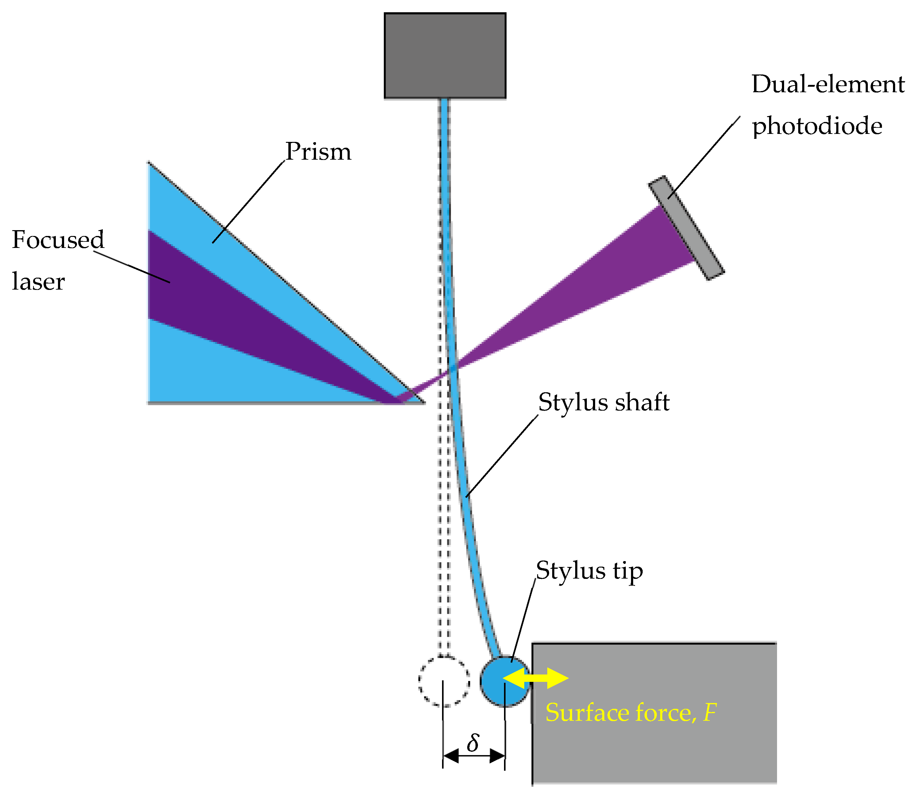
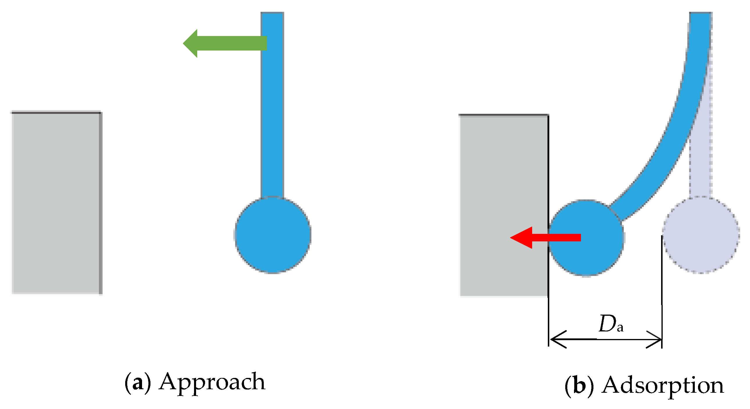
2. Effect of Surface Force

Surface forces mainly consist of van der Waals force, electrostatic force, and liquid bridge force. Van der Waals forces are interactions between molecules (or atoms) and are universal, always acting between objects. Liquid bridge force is an adhesion force caused by liquid bridging formed at a contact area. Force between the charged stylus tip and the measured surface is called electrostatic force [22]. When the charged stylus is brought close to the charged surface to be measured and the distance between the stylus tip and the measured surface becomes 10 µm or below while using the stylus shaft and tips with diameters of 20 and 35 µm, the stylus tip is attracted to the measured surface by the electrostatic force and may stick to it [21]. The adsorption distance decreases as the diameter of the stylus shaft increases. It is necessary to move the stylus approximately 60 µm to pull it away from the measured surface due to liquid bridge force and electrostatic force once it is attached to the measured surface. In humid environments, once the stylus tip makes contact with the measured surface, large liquid bridge force acts between the stylus tip and the measured surface. A stylus shaft with a diameter of several tens of micrometers or more can easily pull the stylus tip away from the measured surface due to its high rigidity. However, when the diameter of stylus shaft is less than several tens of micrometers, the deflection of the stylus shaft is larger, and the stylus movement required to pull it away from the measured surface is larger. Surface forces acting on the stylus tip also decrease as the diameter of the stylus decreases. However, the decrease in stylus stiffness with decreasing diameter is greater than the decrease in surface forces; therefore, the stylus deflection (the distance δ in Figure 1) increases with the decreasing stylus diameter, leading to increased measurement time and reduced measurement accuracy.
In addition, once the stylus tip makes contact with the measured surface, it adheres to the measured surface and is difficult to separate. When measuring with the touch-trigger method, this adhesion increases the measurement time because the stuck tip must be pulled away. When measuring in scanning mode, the stylus shaft may deflect due to surface forces, which can worsen the measurement accuracy.
The van der Waals force and liquid bridge force are sufficiently larger than the electrostatic force when the diameter of stylus tip is approximately 100 µm or less [21]. However, the van der Waals force drops sharply when surface roughness exists on the contact surface. As an example, the van der Waals force for a surface roughness, RZ, of 100 nm is approximately 1/100 of that for a surface roughness, RZ, of 10 nm. Therefore, the liquid bridge force and electrostatic force are considered to have a large influence on the adhesion of the stylus tip to the measured surface. The effect of liquid bridge force is greater in humid environments, whereas the effect of electrostatic force is greater in low-humidity environments or in the case of measuring easily charged materials such as resins. First, we examine the possibility of reducing the liquid bridge force by applying a water-repellent coating to the stylus tip to reduce the adhesion of moisture from the air to the surface of stylus tip.

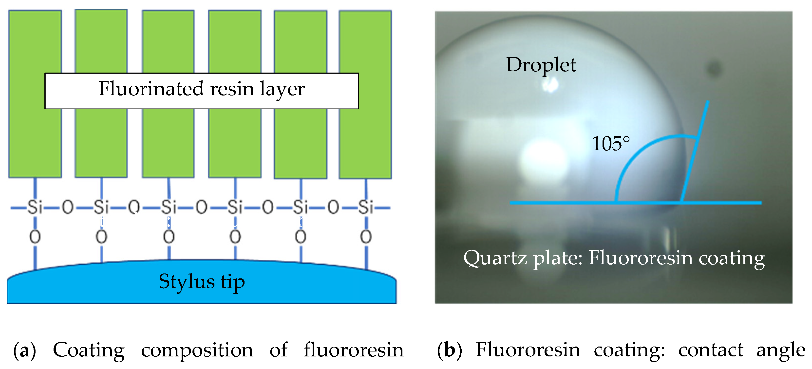
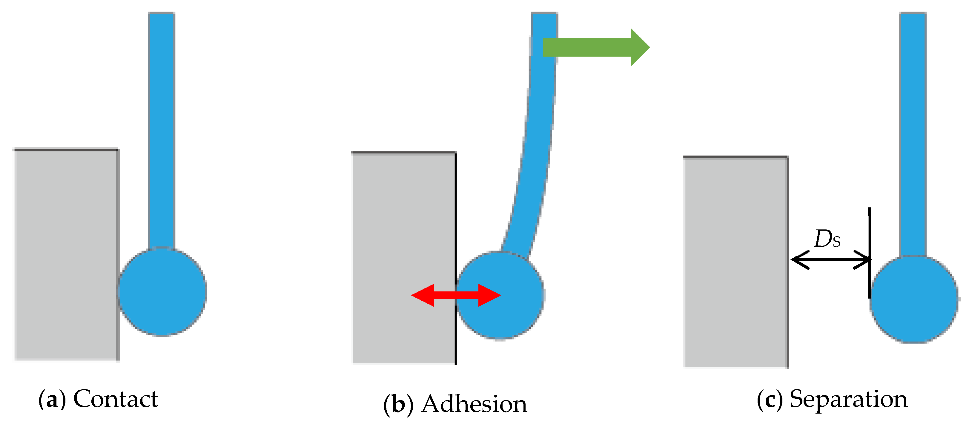
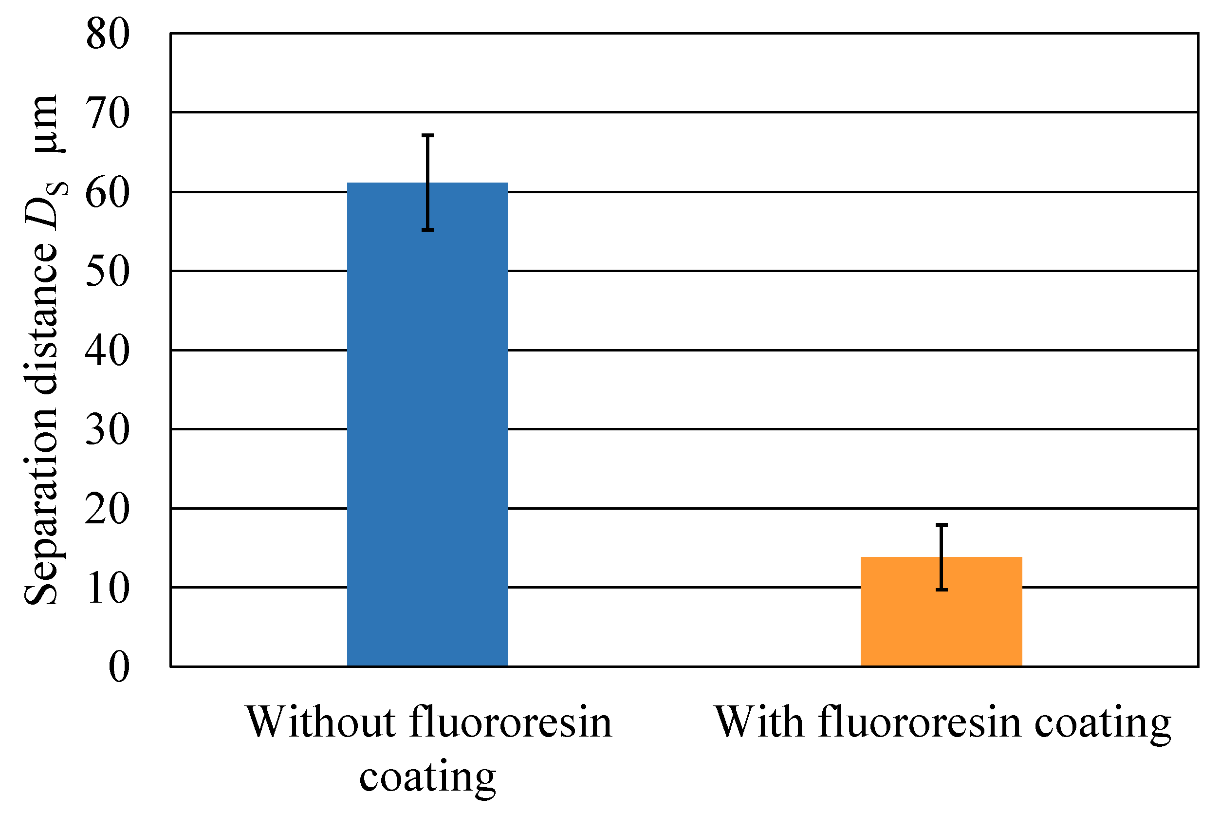
3. Reduction in Liquid Bridge Force by Applying a Water-Repellent Coating to the Stylus Tip

When moisture is present on the stylus tip or the measured surface, liquid bridges are formed between the contacting surfaces at the moment of contact. This liquid bridge generates a liquid bridge force when the stylus tip is pulled away from the measured surface. One possible method to reduce the liquid bridge force is to create a vacuum or low humidity in the measurement environment to prevent water from adhering to the stylus tip [21]; however, it is difficult to create such an environment at the actual measurement site. Therefore, a water-repellent coating was investigated to change the contact angle with the liquid as a method to reduce the influence of liquid bridge force.
This fluoropolymer coating (Fluoro Technology Co., Ltd., Japan, Fluoro Surf FG-5084) shown in Figure 2a reduces the adhesion of water by forming a fluorinated resin layer on the surface. Fluorine-based coatings were selected because of their higher water repellency and durability compared with silicone-based coatings [23]. Figure 2b shows a photograph of a drop of water observed from the horizontal direction on a glass substrate with the fluororesin coating. From this photograph, the contact angle with the fluororesin coating can be determined as 105°.
To evaluate the performance of a stylus coated with a water-repellent coating, the performance test was conducted using styluses with and without the fluororesin coating (tip diameter 35 µm, shaft diameter 20 µm, shaft length 2 mm). The stylus was dipped into the coating solution and then dried in a furnace at 80 °C for 60 min to form a fluorinated resin layer. As shown in Figure 3a,b, the stylus was moved at a pitch of 100 nm by the fine movement positioning XYZ piezo stage (P-562.3 CD, Physik Instrument) [16] away from the measured surface in contact with the stylus tip. The closed-loop resolution of the stage travel was 1 nm, and repeatability in the X-, Y-, and Z-directions was 2.2, 2.2 and 4 nm, respectively. A capacitive displacement sensor was integrated into the stage. The experiment was conducted in a chamber controlled at 20 ± 0.1 °C.
When the stylus is moved further, the stylus tip separates from the measured surface at a certain distance, DS (Figure 3c). The distance, DS, was measured 10 times repeatedly. To eliminate the effect of static electricity, the stylus and the measured surface were ionized with an ionizer before the experiment.
The film thickness of a fluorinated resin layer was estimated to be 10–20 nm from the specifications in the manufacturer’s catalog. The film thickness was assumed to have no effect on the stylus dimension and measurement accuracy because its thickness was below the resolution of this measurement system. The relative humidity during the measurement was 27%. The average separation distances for styluses with and without the fluororesin coating are shown in Figure 4. The results show that the average separation distance without a coating is 61.2 µm and with a fluororesin coating it is 13.8 µm, indicating that the fluororesin-coated stylus reduces the separation distance by approximately 78%. These results confirm that the liquid bridge force is reduced by improving water repellency of the stylus tip. This is thought to be due to a decrease in capillary condensation between the stylus tip and the measured surface by changing the stylus surface from hydrophilic to hydrophobic.

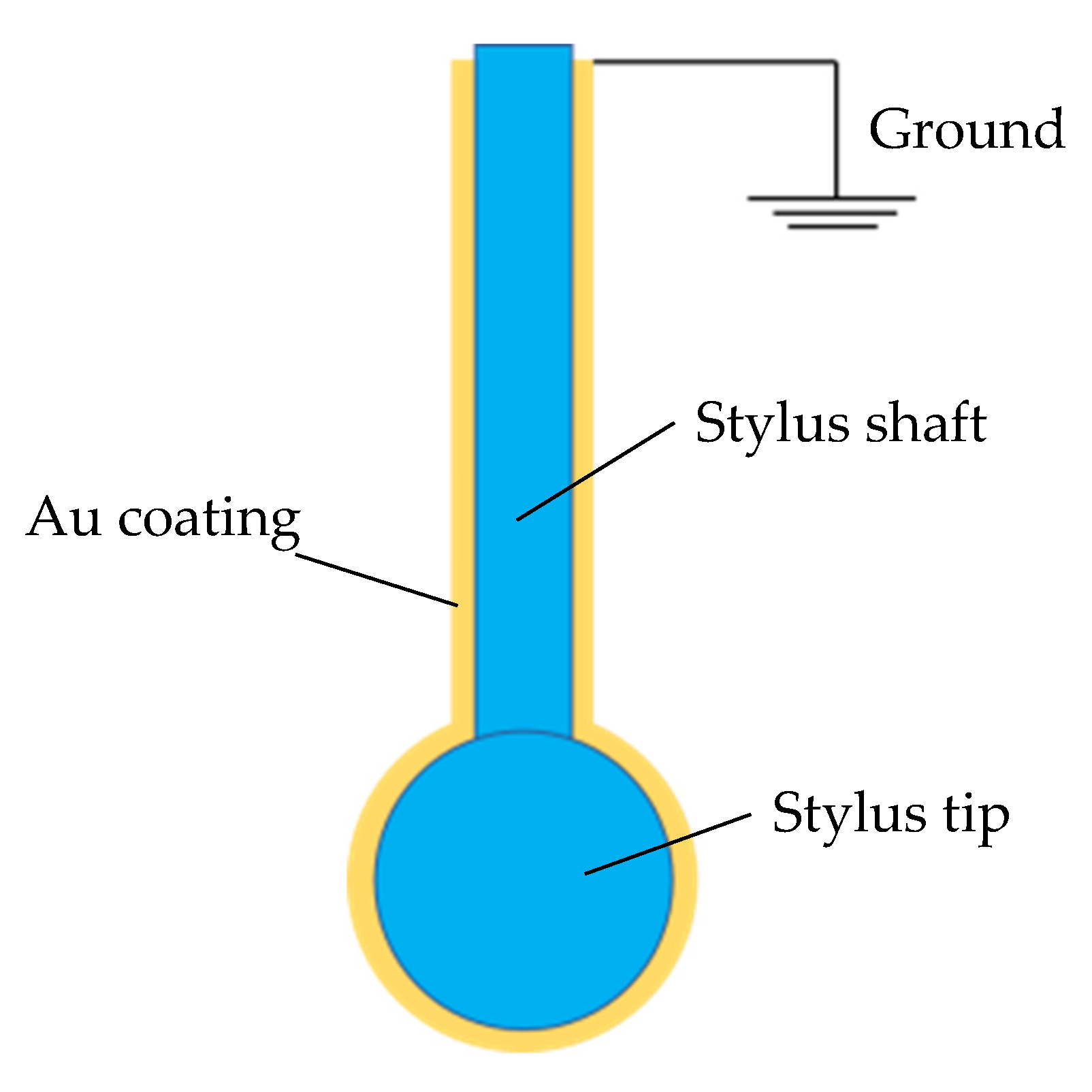
4. Reduction in Electrostatic Force by Applying an Antistatic Coating to the Stylus Tip

Generally, when materials are charged with static electricity, the materials are ionized using an ionizer to supply an electric charge opposite to the charged electric charge to eliminate bias of the electric charge. However, there is a problem that ionizers cannot sufficiently eliminate static electricity inside holes with a small diameter. We investigated whether a stylus with a sputtered metal coating on its surface could be used to reduce the electrostatic force by removing the charge inside the small-diameter hole through the metal coating on the stylus surface. In this study, the stylus was coated with Au to reduce the electrical resistance of the stylus tip surface and promote charge leakage. A nickel ferrule stylus was placed in an Au sputtering apparatus; the entire stylus (tip diameter 35 µm, shaft diameter 20 µm, shaft length 3 mm) was coated with Au as shown in Figure 5; and the rear end face of the ferrule was connected to ground. The film thickness of the Au coating was 3 nm. A conductive adhesive was applied to the boundary between the stylus and ferrule. Figure 6 shows a photograph of the stylus with antistatic coating.
Figure 7 shows an adsorption test conducted between the charged surface and the stylus tip. When the stylus was brought close to the charged surface (Figure 7a) and the distance between the stylus and the measured surface fell below Da (Figure 7b), the stylus adhered to the measured surface due to electrostatic forces. The adsorption distance, Da, was then measured. The material of the measured surface was fluoroplastic, and the surface was charged to −100 V using a charging gun. The adsorption distances for styluses with and without antistatic coating are shown in Figure 8. The adsorption distance of the stylus with an antistatic coating is greater than that of the stylus without an antistatic coating. This is thought to be because when the gold-coated stylus approaches the charged surface, the coated surface of stylus tip is inductively charged with the opposite polarity of the charged surface, increasing the attraction between the charged surface and the stylus tip. To reduce the effect of induced charging, the stylus with an antistatic coating was used to scan the area near the contact point to eliminate static electricity; then, the adsorption test was performed again. As shown in Figure 9, a 200 µm square around the contact point in adsorption test was scanned with the stylus tip in contact at 0.5, 1, and 2 µm pitch in the Z-axis direction to eliminate static electricity. The times required to scan a 200 µm square region are 463, 916, and 1833 s for 2, 1, and 0.5 µm pitch, respectively. The adsorption test was then conducted again. Figure 10 shows the average adsorption distance after scanning. When the scanning pitch in the Z direction was 2µm, there was almost no change in the adsorption distance, but rather, an increase. With a scanning pitch of 1 µm, the adsorption distance was 7.2 µm on average, with a 42% reduction in adsorption distance compared with the uncoated stylus. When the scanning pitch was 0.5 µm, the adsorption distance was 3.6 µm on average, a reduction of 71% in adsorption distance compared with the uncoated stylus.
These results indicate that when measuring the internal shape of a microhole, scanning the inside of the hole first reduces the effects of electrostatic force adhesion, and the time required to pull the attached stylus tip away from the measured surface can be reduced.

5. Conclusions

In this study, we fabricated and evaluated a high-function fiber stylus with a water-repellent and antistatic coating applied to the stylus tip to reduce tip adhesion due to liquid bridge force and electrostatic force, obtaining the following results.
1. When a water-repellent coating using fluororesin was applied to the stylus tip, the effect of liquid bridge force could be reduced by approximately 78%.
2. When the ionization of charged surfaces was performed using the stylus coated with an antistatic coating, the effect of electrostatic force could be reduced by 71%.

Author Contributions

Conceptualization, H.M.; methodology, K.U.; validation, A.K., T.S. and K.F.; formal analysis, A.K. and T.S.; investigation, K.U. and K.F.; data curation, K.U.; writing—original draft preparation, H.M.; writing—review and editing, K.U., A.K., T.S. and K.F.; funding acquisition, H.M. All authors have read and agreed to the published version of the manuscript.

Funding

This research was funded by [METI Supporting Industry Program], [Japan Society for the Promotion of Science (JSPS KAKENHI)] grant number [26420392] and [Japan Science and Technology Agency (JST)] grant number [A-Step].

Institutional Review Board Statement

Not applicable.

Informed Consent Statement

Not applicable.

Data Availability Statement

The data presented in this study are available on request from the corresponding author.

Acknowledgments

This study was partially supported by a research grant from the METI Supporting Industry Program, JSPS KAKENHI Grant Number 26420392 and JST A-Step.

Conflicts of Interest

The authors declare no conflict of interest.

References

  1. Michihata, M. Surface-Sensing Principle of Microprobe System for Micro-Scale Coordinate Metrology: A Review. Metrology 2022, 2, 4. [Google Scholar] [CrossRef]
  2. Fang, F.Z.; Zhang, X.D.; Gao, W.; Guo, Y.B.; Byrne, G.; Hansen, H.N. Nanomanufacturing—Perspective and applications. CIRP Ann. 2017, 66, 683–705. [Google Scholar] [CrossRef] [Green Version]
  3. Thalmann, R.; Meli, F.; Küng, A. State of the Art of Tactile Micro Coordinate Metrology. Appl. Sci. 2016, 6, 150. [Google Scholar] [CrossRef]
  4. Metz, D.; Dietzel, A. 3-D Isotropic Tactile Microprobe Based on a Silicon Parallelogram Kinematic: From Concept to Fabrication. J. Microelectromech. Syst. 2019, 28, 63–76. [Google Scholar] [CrossRef]
  5. Metz, D.; Jantzen, S.; Wessel, D.; Mies, G.; Lüdenbach, J.; Stein, M.; Kniel, K.; Dietzel, A. Integration of an isotropic microprobe and a microenvironment into a conventional CMM. Meas. Sci. Technol. 2019, 30, 115007. [Google Scholar] [CrossRef]
  6. Feng, K.; Cui, J.; Sun, X.; Dang, H.; Shi, T.; Niu, Y.; Jin, Y.; Tan, J. Investigation of a Three-Dimensional Micro-Scale Sensing System Based on a Tapered Self-Assembly Four-Cores Fiber Bragg Grating Probe. Sensors 2018, 18, 2824. [Google Scholar] [CrossRef] [Green Version]
  7. Zou, L.; Ni, H.; Zhang, P.; Ding, X. Assembled Cantilever Fiber Touch Trigger Probe for Three-Dimensional Measurement of Microstructures. Sensors 2017, 17, 2652. [Google Scholar] [CrossRef] [Green Version]
  8. Petz, M.; Tutsch, R.; Christoph, R.; Andraes, M.; Hopp, B. Tactile–optical probes for three-dimensional microparts. Measurement 2012, 45, 2288–2298. [Google Scholar] [CrossRef]
  9. Michihata, M.; Takaya, Y.; Hayashi, T. Improvement of Laser Trapping Based Microprobe in Laser Shaded Condition. J. Adv. Mech. Des. Syst. Manuf. 2012, 6, 764–770. [Google Scholar] [CrossRef] [Green Version]
  10. Bian, X.; Cui, J.; Lu, Y.; Tan, J. Ultraprecision Diameter Measurement of Small Holes with Large Depth-To-Diameter Ratios Based on Spherical Scattering Electrical-Field Probing. Appl. Sci. 2019, 9, 242. [Google Scholar] [CrossRef]
  11. Zhang, R.; Wu, S.; Liu, L.; Lu, N.-H.; Fu, X.; Gao, S.-T.; Hu, X.-D. A CD probe with a tailored cantilever for 3D-AFM measurement. Meas. Sci. Technol. 2018, 29, 125011. [Google Scholar] [CrossRef]
  12. Ren, Z.; Wang, D.; Jing, W.; Wang, S.; Jiang, Z.; Ren, J.; Gu, H.; Wei, X. A probe-type high-precision micro-force sensor based on quartz DETF resonator. Meas. Sci. Technol. 2021, 32, 115107. [Google Scholar] [CrossRef]
  13. Ito, S.; Shima, Y.; Kato, D.; Matsumoto, K.; Kamiya, K. Development of a Microprobing System for Side Wall Detection Based on Local Surface Interaction Force Detection. Int. J. Autom. Technol. 2020, 14, 91–98. [Google Scholar] [CrossRef]
  14. Schuler, A.; Hausotte, T.; Sun, Z. Micro- and nanocoordinate measurements of micro-parts with 3-D tunnelling current probing. J. Sens. Sens. Syst. 2015, 4, 199–208. [Google Scholar] [CrossRef] [Green Version]
  15. Manske, E.; Fröhlich, T.; Füßl, R.; Ortlepp, I.; Mastylo, R.; Blumröder, U.; Dontsov, D.; Kühnel, M.; Köchert, P. Progress of nanopositioning and nanomeasuring machines for cross-scale measurement with sub-nanometre precision. Meas. Sci. Technol. 2020, 31, 085005. [Google Scholar] [CrossRef]
  16. Murakami, H.; Katsuki, A.; Sajima, T.; Uchiyama, K.; Yoshida, I.; Hamano, Y.; Honda, H. Development of measurement system for microstructures using an optical fiber probe: Improvement of measurable region and depth. Meas. Sci. Technol. 2020, 31, 075902. [Google Scholar] [CrossRef]
  17. Murakami, H.; Katsuki, A.; Sajima, T.; Uchiyama, K. Fabrication of Ultra-Small-Diameter Optical-Fiber Probe Using Acid-Etch Technique and CO2 Laser for 3D-Micro Metrology. Int. J. Autom. Technol. 2017, 11, 699–706. [Google Scholar] [CrossRef]
  18. Murakami, H.; Katsuki, A.; Sajima, T.; Suematsu, T. Study of a vibrating fiber probing system for 3-D micro-structures: Performance improvement. Meas. Sci. Technol. 2014, 25, 094010. [Google Scholar] [CrossRef]
  19. Uchiyama, K.; Murakami, H.; Katsuki, A.; Sajima, T. Development of a Sharp-Tipped L-Shaped Stylus for Measurement of Nanoscale Sidewall Features. Int. J. Autom. Technol. 2022, 16, 489–496. [Google Scholar] [CrossRef]
  20. Murakami, H.; Murakami, H.; Katsuki, A.; Sajima, T.; Uchiyama, K. Development of a two-step stylus with elastic hinge for microstructure measurement to improve sensitivity and vibration characteristics. Precis. Eng. 2023, 80, 72–81. [Google Scholar] [CrossRef]
  21. Murakami, H.; Katsuki, A.; Sajima, T.; Fukuda, M. Reduction of Liquid Bridge Force for 3D Microstructure Measurements. Appl. Sci. 2016, 6, 153. [Google Scholar] [CrossRef] [Green Version]
  22. Okuyama, K.M.H.; Morooka, S. Fine Particle Engineering; Ohmsha: Tokyo, Japan, 1992; pp. 32–40. [Google Scholar]
  23. Uchiyama, H.M.K.; Katsuki, A.; Sajima, T.; Yamamoto, R.N.T.; Fujiyoshi, K. Fabrication of a fiber probe using a CO2 laser for microstructure measurement: High functionality and durability test. Procedia CIRP 2018, 77, 513–516. [Google Scholar] [CrossRef]
Figure 1. Effect of the surface force, F, during measurement.
Applsci 13 01260 g001
Figure 2. Coating composition and contact angle of the droplet.
Applsci 13 01260 g002
Figure 3. Measurement method of separation distance.
Applsci 13 01260 g003
Figure 4. Influence of fluororesin coating on the average separation distance.
Applsci 13 01260 g004
Figure 5. Structure of the stylus with an antistatic coating.
Applsci 13 01260 g005
Figure 6. Photograph of the stylus with an antistatic coating.
Applsci 13 01260 g006
Figure 7. Measurement method of adsorption distance.
Applsci 13 01260 g007
Figure 8. Influence of antistatic coating on the average adsorption distance.
Applsci 13 01260 g008
Figure 9. Ionizing method of charged surface using the stylus with a gold coating.
Applsci 13 01260 g009
Figure 10. Influence of antistatic coating on the average adsorption distance when measured by changing the scanning pitch in the Z direction to 0.5, 1, and 2 µm pitch.
Applsci 13 01260 g010
Disclaimer/Publisher’s Note: The statements, opinions and data contained in all publications are solely those of the individual author(s) and contributor(s) and not of MDPI and/or the editor(s). MDPI and/or the editor(s) disclaim responsibility for any injury to people or property resulting from any ideas, methods, instructions or products referred to in the content.

