1. Introduction
In order to achieve carbon neutrality, many countries have introduced policies to support non-fossil energy sources, and nuclear energy is developing rapidly as a low-carbon non-fossil energy source [
1,
2,
3,
4]. However, the development of nuclear energy has also brought tragic accidents to mankind [
5], which makes nuclear safety ever more important [
6]. There are six types of Generation IV nuclear reactors designed with safety in mind, namely, VHTR, GFR, MSR, LFR, SFR, and SCWR [
7], which are considered to solve the obvious problems of existing reactor types [
8]. The high-temperature gas-cooled reactor (HTR) is considered a promising Generation IV nuclear reactor due to its inherent safety [
9,
10,
11]. The construction of the first commercial HTR-PM was initiated at Shidao Bay, Rongcheng, Shandong province, China, in 2012, and is in the commissioning stage [
12,
13,
14].
HTR can be divided into hexagonal prismatic and pebble-bed high-temperature gas-cooled reactors based on the geometry of the fuel. The fuel elements of prismatic high-temperature gas-cooled reactors use hexagonal graphite blocks and are arranged in the longitudinal direction of the core, with the active cores distributed in an annulus shape in the lateral direction, and each standard fuel element consists of burnable poison rods, compact fuel rods, large coolant channels, and small inner coolant channels [
15,
16,
17]. The fuel element of a pebble-bed high-temperature gas-cooled reactor is a fuel sphere consisting of a fuel core and a fuel-free shell, which takes advantage of the fluidity of the sphere to ensure its circulation capability, allowing the input of fresh and unexhausted fuel without stopping the reactor. When the fuel elements are discharged from the bottom of the core, the unexhausted fuel elements are screened and fed into the reactor together with fresh fuel through the fuel-lift system, which ensures fuel utilization.
The fuel-element pneumatic lifting system uses pneumatic transportation to cycle the fuel element. Thousands of elements are discharged from the bottom of the core and lifted to the top of the core by the continuous airflow in a spatially oriented transport pipeline [
18]. The diameter of spherical fuel elements is very close to the inner diameter of the conveying pipeline, with the diameter ratio ranging from 0.92 to 0.97. Therefore, this conveying method is called “near-equal diameter spherical flow pipeline pneumatic conveying.”
Figure 1 shows a schematic diagram of the motion of the fuel element. A Cartesian system attached to the sphere is used to express the axial, lateral, and rotational motions. During its motion from the steering section of the bend to the vertical section, the fuel element will move in the plane where the axis of the bend is located due to the centrifugal force in the bend, and the dotted line in the figure illustrates the trajectory of the center of mass of the fuel element. The motion of the fuel element can be decomposed into translational motion
along the axis of the pipe (along the
z-axis direction), transverse motion
perpendicular to the axis of the pipe (along the
x-axis direction), and rotational motion
. Shen et al. [
19] pointed out that in the process of pneumatic transportation of fuel balls, the collision will lead to the formation of graphite dust, and the accumulation of graphite dust will affect the stability and reliability of the reactor. Therefore, it is imperative to analyze the dynamics of the motion process.
Asim et al. [
20] studied the process of pipeline transport of fuel elements with water as the medium and explored the effect of each parameter of the element but did not carry out a kinetic study. German scholars studied the motion of fuel elements along the axial pipeline direction during the transport process [
21,
22,
23] but did not take account of the complex motion behavior of highly coupled fuel elements (axial lateral shift of the vertical pipeline, collision, and friction with the pipeline wall, etc.), nor did they carry out experimental studies of the fuel-element operation process in the pipeline. Shen et al. [
24] obtained the transverse coefficients C
d and C
y and the torque coefficient C
m of the fuel element based on CFD and established the equations of the motion of the fuel element accordingly. Liu et al. [
25] performed a dynamic analysis of the motion process of the fuel element and derived the equations of the motion. Liu et al. [
26] simulated the flow field using a structural mesh of fluid dynamics and performed a force analysis of the fuel element. However, previous studies focused on typical bends (pipe axis in the vertical plane) and did not consider atypical bends (pipe axis not in the vertical plane, as in
Figure 2), which leads to a large error in the model calculation.
In this paper, the kinetic model of the fuel element in an atypical bend is established in
Section 2. The kinetic characteristics of the fuel element and the influence of the pipe parameters on its motion are analyzed and discussed by numerical simulations in
Section 3. The experimental results are verified by building an experimental platform in
Section 4.
Section 5 discusses the hazards and ideas for solutions regarding collisions between fuel elements and piping.
Section 6 concludes the paper with suggestions for the design and optimization of the fuel-element lifting system of a pebble-bed reactor and provides a direction for future research.
3. Analysis of the Motion Characteristics of Fuel Elements
Based on the above fuel-element pneumatic-lifting-system kinetic model, the numerical-simulation method is used to analyze the motion characteristics in the fuel-element pipeline. The values of the basic parameters of the model are shown in
Table 2. The diameter ratio of the spheres/pipe, the inclination angle of the pipe, the collision recovery coefficient, and the bending radius of the pipe are important parameters to describe the pipe structure [
28], and the range of parameters is based on the basic working conditions of the pneumatic lifting system of the fuel elements of the pebble-bed reactor. The pneumatic forces
,
, and
on the fuel elements in the straight pipe, typical, and atypical bends, respectively are calculated according to Equations (18)–(20), respectively [
24].
where
is the traction coefficient,
is the lateral-force coefficient,
is the torque coefficient,
is the windward area of the fuel element,
is the diameter of the fuel element,
is the gas density, and
is the incoming-gas velocity.
The fuel element runs along the conveying pipeline under the action of gas power, which will show three kinds of motion states. These are the acceleration process, balance-lifting process, and bend-motion process, as shown in
Figure 6. Under each motion state, the pipeline-structure parameters have a significant influence on the motion characteristics of the fuel element.
3.1. Analysis of Acceleration-Process Motion of Fuel Elements
Figure 7a–d shows the axial velocity, lateral velocity, lateral displacement, and rotational angular velocity versus time for the fuel element in the horizontal straight-pipe section, respectively, and
Figure 7e shows the effect of the sphere/pipe-diameter ratio and pipe-inclination angle on the motion of the fuel element.
Figure 7a shows that the axial velocity
of the fuel element under the action of pneumatic force increases rapidly from 0 to 5.1 m/s in 0.2 s, then
increases slowly until it is close to the lifting gas-flow velocity
(
is indicated by the dashed line in the figure, taking 6 m/s as an example). According to the kinetic model, the winding velocity of gas (the difference between
and
) is larger in 0–0.2 s, so the pneumatic thrust
is larger and the axial acceleration of the fuel element (the slope of
) is large. Its collision with the inner wall of the pipe leads to the instantaneous reduction of the axial velocity
(reflected as the zigzag step of the
curve), the collision-recovery coefficient
(about 0.8) prompts the collision to gradually weaken, and finally
and
only have a small velocity difference caused by the rolling friction of the fuel element.
Figure 7b,c displays the transverse velocity and transverse motion trajectory of the fuel element. When the transverse displacement reaches –1 mm and 1 mm, it means that the fuel element collides with the upper and lower wall surfaces of the pipe, respectively (the diameter of the fuel element
is 60 mm and the inner diameter of the pipe
is 62 mm). The collision time
is extremely short, and it is reflected as a point on the time axis t. The transverse velocity
of the fuel element gradually decreases from 1 m/s to nearly 0. The decay of the transverse motion is synchronized with the appearance of the jagged step on
. At the end of each collision, the fuel element runs in the reverse direction with the velocity
(the product of the velocity
and
before this collision), and after 0.25 s it will roll against the lower wall of the pipe.
Figure 7d shows the change in the rotational angular velocity
of the fuel element with time. Within 0–0.25 s, when the fuel element collides with the pipe, its rotational angular velocity shows a positive or negative instantaneous step (the collision time is very short; the friction of the collision process produces the instantaneous torque acting on the fuel element). From the fuel-element pneumatic-lifting-system kinetic model, the instantaneous torque generated by the collision process is much larger than the torque
generated by the lifting airflow, so the change in
caused by the collision process will be much larger than the change in
caused by
(i.e., the
curve shows the step-like characteristics). When the collision ends after 0.25 s, the fuel element rolls against the lower wall of the pipe due to gravity. At this point, the sliding between the fuel element and the inner wall of the pipe can be ignored and only the pure rolling friction state is considered.
The effect of the sphere/pipe-diameter ratio and pipe-inclination angle on the motion characteristics of the fuel-sphere acceleration process is shown in
Figure 7e. the sphere/pipe-diameter ratio and pipe-inclination angle increase, the final velocity of the fuel element increases, and the time to reach the final velocity is shortened. In the case of k = 0.92, the axial velocity takes 0.2 s to accelerate to about 4 m/s, whereas in the case of k = 0.97, the axial acceleration is greater and the acceleration time is shorter, taking only 0.1 s to accelerate to about 5 m/s. The effect of increasing the pipe-inclination angle to 30° is not significant, and it is easy to see that the main factor affecting the acceleration process is the sphere/pipe-diameter ratio; the fuel element continuously collides with the inner wall of the pipe during the acceleration process, and the axial motion of the fuel element slows down at the moment of collision, i.e., the collision slows down the acceleration process of the fuel element.
3.2. Analysis of the Motion of the Vertical-Lifting Part of the Fuel Element
Figure 8a–d shows the curves of axial velocity
, transverse velocity
, transverse displacement
, and rotational angular velocity
of the fuel element in a straight-pipe section perpendicular to the horizontal plane (i.e.,
= 90°), respectively, as a function of time, and
Figure 8e shows the effect of the sphere/pipe-diameter ratio and recovery factor on the motion of the fuel element.
When the fuel element enters the vertical-lifting section from the bend-turning section at the beginning (i.e., within 0.1 s time), its transverse velocity
is larger and the collision between the fuel element and the inner-wall surface of the pipe is frequent and violent, which makes the axial velocity
drop rapidly. As shown in
Figure 8a,
drops rapidly from 5.1 m/s to 3.8 m/s.
In 0.1–0.6 s, the collision intensity decays gradually. As shown in
Figure 8b,c, the transverse velocity
of the fuel element decreases significantly, the frequency of the collision decreases, and its axial velocity
differs from the gas-flow velocity
(shown as a dashed line in
Figure 8a), and the fuel element completes the re-acceleration process rapidly due to the pneumatic thrust
.
After 0.6 s, the fuel element no longer collides with the inner wall of the pipe; its axial velocity is basically stable, referring to the kinetic model of the fuel-element pneumatic lifting system. The difference between this and the lifting gas-flow velocity is mainly caused by gravity, and the difference is the delayed velocity of the fuel element. The lateral velocity and lateral displacement x of the fuel element fluctuate reciprocally around 0 and have a tendency to gradually decrease. With reference to the kinetic model of the fuel-element pneumatic lifting system, the lateral force on the fuel element is always directed to the center of the pipe, which has the effect of maintaining its movement along the axis of the pipe and gradually weakening the lateral movement. The rotational angular velocity of the fuel element is also basically stable during this period, and the variation in under the action of the aerodynamic component is very small. In summary, at this time, the fuel element enters the smooth lifting stage without collision with the pipe and has a high and stable axial velocity, which is the best state for the pneumatic lifting process of the pebble-bed-reactor fuel element.
The effect of the sphere/pipe-diameter ratio and recovery factor on the motion characteristics of fuel-element vertical-lifting process is shown in
Figure 8e. Due to the change in the direction of motion at the beginning of the vertical-lifting process, the fuel element collides violently with the inner wall of the pipe, and the axial velocity of the fuel element drops significantly. Lowering the recovery factor
could reduce the strength and frequency of collisions, which in turn reduces the magnitude of the velocity drop and the level of cyclic stress on the pipe (setting a bellows at the front of the vertical-lifting section and relaxing the pipe constraint can effectively reduce
); then, the collision starts to decay, and the fuel element is lifted vertically with the characteristic axial velocity
(the small fluctuation of
is caused by the transverse motion
and rotational motion
of the fuel element). The difference between
and the gas-flow velocity (6 m/s, for example) is the delay velocity
. Increasing the ball/pipe-diameter-ratio k can reduce the delay velocity and increase
while making the vertical-lifting process smoother.
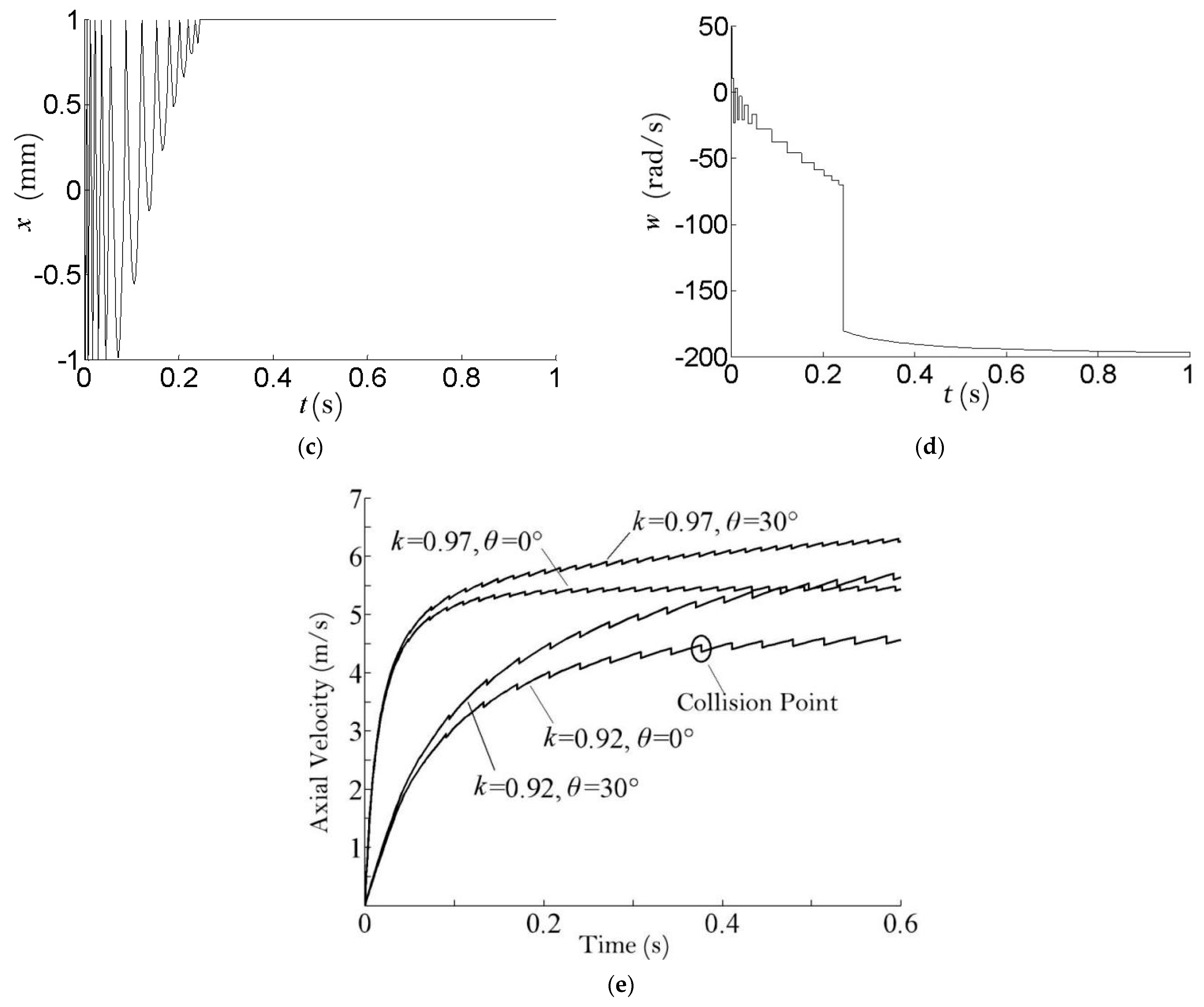
3.3. Analysis of the Motion of Fuel Elements in Atypical Bends
Figure 9a–d shows the curves of axial velocity
, transverse velocity
, transverse displacement x, and rotational angular velocity w of the fuel element in an atypical bend with time, respectively, and
Figure 9e shows the effect of the sphere/pipe-diameter ratio and pipe-bending radius on the motion of the fuel element in the deceleration section.
At the beginning of the fuel element entering the bend, its transverse velocity
is large and the collision between the fuel element and the inner-wall surface of the pipe is frequent and violent, which makes its axial velocity
drop rapidly. As shown in
Figure 9a,
drops rapidly from 4.9 m/s to 2 m/s. After that, the collision strength decays rapidly, and the transverse velocity
of the fuel element decreases significantly (as shown in
Figure 9b,c). Due to the pneumatic thrust
, the fuel element will undergo a re-acceleration process. The decay of the lateral motion of the fuel element in the bend is more significant than in the horizontal straight pipe (
Figure 7) because of the larger centrifugal force in the bend. After 0.15 s, the collision process ends and the fuel element rolls against the outer wall of the pipe (x = 1 mm wall), and its rotational angular velocity
in the pure rolling state is determined by
/
, as shown in
Figure 9d.
The effect of sphere/pipe-diameter ratio and pipe-bending radius
on the motion characteristics of fuel-element deceleration section is shown in
Figure 9e. Decreasing the sphere/pipe-diameter ratio
and pipe-bending radius
can limit the final velocity of the fuel element during the whole pneumatic lifting process, i.e., reduce the impact velocity
of the fuel element on the core. When the sphere/pipe-diameter ratio is 0.97, the axial velocity of the fuel element only decreases slightly for a short time, and the impact velocity
is greater than 5.5 m/s. When the sphere/pipe-diameter ratio is 0.92 and the pipe-bending radius is 0.4 m, the deceleration effect is obvious, and the impact velocity
of the fuel element on the core drops to 4.3 m/s. In summary, a larger sphere/pipe-diameter ratio will have a greater impact velocity. A smaller bending radius has a more pronounced deceleration during the collision phase, but its recovery rate is faster and the impact velocity is smaller. The choice of a larger sphere/pipe-diameter ratio and a smaller bending radius will help to ensure the integrity of the fuel elements and the safety of the reactor interior.
4. Test System and Experimental Results
In order to study the accuracy of the fuel-element lifting-system-dynamics model, a visualization experimental platform was built. In order to facilitate observation and data acquisition, φ60 mm colored Plexiglas spheres were used as fuel elements in this experimental platform, and transparent Plexiglas pipes were used to build the lifting pipeline.
Referring to the structural characteristics of the lifting pipeline of the pebble-bed reactor, several straight-pipe sections and bent-pipe sections were connected by flanges to form the lifting pipeline of the experimental platform, and the lifting height was 15 m in the experiment. The motion image of the sphere was recorded by a high-speed camera, and the gas-state parameters were collected by a manometer and a flow meter, as shown in
Figure 10. The experimental equipment included a roots fan, manometer, regulating valve, thermometer, flow meter, dosing device, and diverter. The roots fan is the gas-power source, whose rated pressure is 98 kPa. The manometer monitors the gas pressure. The regulating valve regulates the flow rate of the lifting gas. The thermometer monitors the temperature of the lifting gas. The flow meter monitors the flow rate of the lifting gas. The dosing device can temporarily store the spherical components and add them to the lifting pipe accordingly. The straight pipe with an inner diameter of φ60 mm and the bent pipe are connected to form the circulation channel of the sphere. The diverter is used to divert the lifting airflow out of the pipeline. The collector stores the fuel elements lifted to the top.
The roots fan is used to generate gas power. The gas flow is regulated by a regulating valve, which passes through a cooler, a thermometer, a pressure gauge, and a gas-flow meter before reaching the inlet of the dosing device. A 60 mm-diameter mock-up of the fuel element (colored Plexiglas sphere) passes through the dosing device into a 65 mm inner-diameter Plexiglas conveying duct and is driven by a continuous air flow to a collection device at a height of 15 m. The air density during the test was 1.2 kg/m
3 and the gas-flow rate was 9.4 m/s. To measure the running speed of the simulated parts during the conveying process, a high-speed camera recorded the motion of the simulated parts and output a series of motion images, as shown in
Figure 11.
Figure 12 shows the comparison between the theoretical and experimental values of the axial velocity of the simulated parts during the whole conveying process, and each data point is the average velocity of the simulated parts at the corresponding motion distance. When the axial displacement of the simulated part was in the range of 0~14 m, the axial velocity calculated by the kinetic model of fuel-element lifting system was in good agreement with the experimental value, with a deviation within 7%. During the experiment, when the simulated part passed through the bend (axial displacement of 16 m), the velocity dropped significantly and the experimental value deviated from the theoretical value. The reason for the deviation may be that the diameter ratio of the ball/pipe in the bend section was less than 0.92, resulting in a significant reduction in the pneumatic thrust provided by the airflow. The phenomenon can be explained as follows: as the bend pipe installed on the test platform was made from a straight-pipe section with a 65 mm inner diameter by a hot-bending formation process, the inner diameter of the local pipe was larger than 65 mm during the manufacturing process.
5. Discussion
In the above study, it was found that the fuel element undergoes violent velocity changes at specific locations in the accelerating-pipe section, vertical-lifting-pipe section, and decelerating-pipe section during the lifting process, accompanied by collisions of different intensities and frequencies. The main parameters affecting the collisions are the sphere/pipe-diameter ratio and recovery coefficient. Although the higher sphere/pipe-diameter ratio leads to an increase in the collision frequency, it limits the intensity of its collision and speeds up the process from the unstable phase to the stable phase. The smaller recovery factor results in more lateral velocity being consumed in the event of a collision, thus reducing the frequency and intensity of subsequent collisions.
Collisions also pose a hidden risk for the long-term safe operation of the fuel-lift system. For the fuel element, the collision will lead to wear of the fuel-free shell, which is only 5 mm thick, and there is a risk that the fuel core will be exposed due to excessive wear. Secondly, since the clearance between the pipe and the fuel element is only 1 mm, the graphite dust generated by the collision may lead to clogging of the fuel element, which may cause more serious accidents. For the pipe, the collision will cause impact stress in the pipe, and there is uneven distribution of impact-stress intensity in different pipe sections and uneven distribution of impact-stress location in the same pipe section.
For collision hazards, first, a larger sphere/pipe-diameter ratio and a smaller recovery factor can be used to reduce the frequency and intensity of collisions. In addition, the core-exposure problem can be prevented by testing the shell integrity of the fuel element during consumption testing. Secondly, the air-pressure monitoring method (when the fuel-element lifting system is clogged, a prolonged high air-pressure condition will be formed in the pipe below the clogged position) can be considered to detect whether the fuel element is clogged. Finally, the high-frequency location from the collision is reinforced to prevent damage to the piping.
6. Conclusions
In this paper, a fuel-element lifting-system kinetic model is proposed and developed to describe the fuel-element transport process in a pebble-bed reactor. On this basis we calculated important parameters, such as axial velocity, rotation speed, and lateral displacement of the fuel element. The results are as follows:
- (1)
The fuel element accelerated to 85% of the airflow velocity in the first 0.2 s of the accelerating-duct-section movement and finally stabilized at 93% of the airflow velocity. The collision occurred in the first 0.25 s, in which the collision between the fuel element and the lower wall of the pipe is dominant.
- (2)
The motion speed of the fuel element in the vertical-lifting-pipe section first plummeted from 5.1 m/s to 3.8 m/s in the first 0.1 s, then gradually increased and stabilized at 5.1 m/s in 0.6 s, where the collision occurred in the first 0.7 s, and then entered a stable lifting state.
- (3)
The velocity change of the fuel-element movement in the bend was similar to that of the vertical-lifting-pipe section, and its collision occurred mainly between the fuel element and the outer side of the inner wall of the bend, which was maintained for about 0.15 s.
The experimental results verify the accuracy of the analysis. This study provides the basis for optimization of the pebble-bed-reactor fuel-element delivery system, including:
- (1)
When designing the acceleration-pipe section, the acceleration time can be shortened by increasing the sphere/pipe-diameter ratio and the pipe-inclination angle.
- (2)
When designing the vertical-lifting-pipe section, the intensity and frequency of collisions can be reduced by decreasing the recovery factor , with the setting bellows at the front of the vertical-lifting-pipe section serving as an effective way to reduce the recovery factor ; the efficiency can also be improved by increasing the sphere/pipe-diameter ratio.
- (3)
When designing the reduction section, the axial velocity of the fuel element can be reduced by decreasing the sphere/pipe-diameter ratio and the bending radius of the pipe to ensure the integrity of the fuel element and the safety of the reactor core.
- (4)
When designing the pipe thickness and support, according to the collision strength and frequency, the thickness or support of the lower half of the acceleration section of the piping and the outside of the bend can be added.
Most of the current research on fuel-lifting systems is about the lifting process of a single fuel element, but multi-fuel-element lifting in groups is a promising research direction for improving efficiency.


