Abstract
The aim of this study was to design operation methods for three-stage coil gun experiments and to fabricate and compare prototypes of control systems using these methods. Two methods are proposed: (1) recognizing the position of a projectile using a photointerrupter and (2) operating a control circuit to supply power to a silicon-controlled rectifier when the projectile reaches an intended position by registering the delay time between coil gun operations. The distance between the projectile and the solenoid coil during a coil gun operation is a key design factor. For the multi-stage coil gun manufactured in this study, the discharge time must be determined according to the position of the projectile, which moves at high velocity. Therefore, the selected method should have minimal operation error and allow the circuit to be easily used according to the coil gun stage and configuration. This study compares the prototypes of coil gun discharge circuits that were fabricated based on the proposed methods by applying them to three-stage coil guns and measuring their velocities. The findings of this study could be used to suggest design methods for experimental models for coil guns with fewer stages according to the final velocity and coil gun stage to be manufactured.
1. Introduction
An electromagnetic launcher (EML) accelerates a projectile using electrical energy. EMLs are broadly classified as rail guns and coil guns according to the method used to convert electromagnetic force into kinetic energy [1]. In rail guns, Lorentz force is applied to a projectile located between two rails through which current flows, and coil guns accelerate projectiles using the electromagnetic force generated by a current applied to a cylindrical solenoid coil [2].
EMLs do not use chemical energy such as that from gunpowder, so they have no restrictions on firing conditions as long as there is a charging environment with a power supply. For this reason, EML systems have received extensive attention in research for defense and space-launch vehicles [3,4]. In particular, recent research has focused on applying an EML to an aircraft catapult as an accelerator that allows fighter jets to take off from aircraft carriers, as well as the actual deployment of an EML on an aircraft carrier. An electromagnetic injection device has also been developed to replace compressed vapor injection devices, which are currently used on U.S. aircraft carriers [5,6].
A coil gun primarily comprises a solenoid coil to generate electromagnetic forces and a direct current (DC) power supply to apply power to the solenoid coil. Coil guns typically include a capacitor as a power supply to instantaneously apply high voltage and high current. Devices such as SCRs, IGBTs, and FETs are used to maintain the stability of the high voltage and high current flowing in the charging circuit for the capacitor and in the coil gun circuit [7]. Single-stage coil guns have limited capability for accelerating a projectile due to the magnetic saturation point of the solenoid coil. Addressing this limitation in acceleration performance requires a multi-stage coil gun design. A coil gun circuit with suitable configuration for acceleration according to the launcher velocity can greatly accelerate a projectile in theory.
To realize an efficient acceleration in the coil gun, the components of the coil gun must be analyzed in terms of their relationships to the launcher velocity. Recent efforts have been made to optimize the coil gun components, which include the solenoid coil, the shape of the projectile, and power supply such as a capacitor, which act together to determine the launch velocity [8,9].
One of the design elements of the coil gun system is the distance between the projectile and the solenoid coil during discharge. In the coil gun device utilizing capacitors, the current applied to the solenoid coil is not constant, and the magnitude of the applied electromagnetic force constantly changes according to the position of the projectile [10]. The current that moves through the electric subsystem is underdamped due to the capacitance, inductance, and self-resistance of coil winding, so discharge must be controlled according to the position of the moving projectile.
For a multi-stage coil gun, the configuration of the discharge control system to discharge the coil gun is problematic when the projectile reaches an intended position because discharge must be controlled according to the position of the moving projectile. Kim used coil guns with two different types of control circuits: one based on physical contact between a projectile and a discharge circuit, and another with a photodeflector [11]. The latter is based on the detection of infrared rays reflected by the projectile, but it recorded large errors during secondary acceleration. The physical contact method also has disadvantages: the position of the projectile needs to be readjusted every time the switch is turned on, and an impact from turning the switch may cause damage.
These problems were addressed by configuring a coil gun system with a discharge control circuit based on a delay [12]. Although this system has smaller operating errors than those using physical contact and photodeflector methods, the delay time needs to be adjusted through trial and error to find the discharge timing. Moreover, the higher the launcher velocity is, the more difficult it is to adjust the delay time because the adjustment range must be set more finely as the velocity increases. Furthermore, during launch, the position of the solenoid coil is misaligned due to recoil, which causes error. Therefore, the present study presents a control method for coil gun discharge with a photointerrupter sensor. Coil gun systems with a photointerrupter sensor were designed, their prototypes were fabricated to measure the launcher velocity, and their errors were compared with those of the other coil gun systems using the delay approach.
2. Coil Gun Circuit Design
To design the coil gun circuit, the shape of the projectile must first be determined. As the weight of the projectile decreases, the magnitude of the mechanical force essential to accelerate the projectile also decreases. The force acting on the projectile decreases with the decrease in its volume, but the magnitude of the electromagnetic force to accelerate the projectile increases. Conversely, as the weight of the projectile increases, the electromagnetic force received by the projectile increases, and the magnitude of the electromagnetic force required for acceleration also increases. Therefore, a coil gun circuit must be designed to fit the shape and acceleration of the projectile based on the capacitance, coil winding, the diameter of the copper wire used to fabricate the solenoid coil, and the mass of the projectile. The projectile was made of 1010 steel and weighed 11.35 g. Figure 1 shows the projectile used for the simulation and experiment.
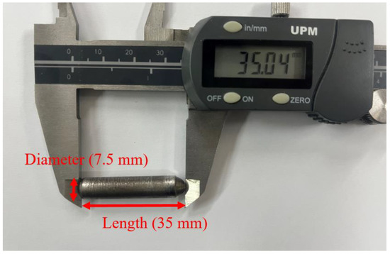
Figure 1.
Projectile for experiment.
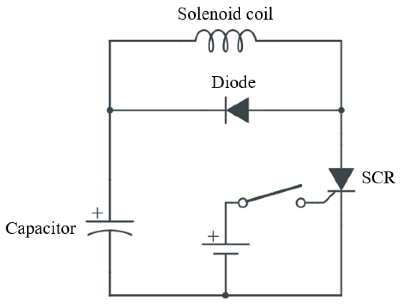
Following the selection of the projectile, the coil gun circuit was designed. The coil gun circuit primarily comprises a solenoid coil and a DC power supply, for which a capacitor is used to instantaneously apply a large current. To use a capacitor, a circuit for charging it and a DC power supply are needed. Moreover, during discharge from the capacitor, a current as high as over 400 A flows through the solenoid coil. Therefore, devices such as SCRs are required to control the high voltage and current generated during operation of the coil gun circuit. Figure 2 shows the circuit diagram of a single-stage coil gun, including a charging circuit and a discharge circuit with an SCR.

Figure 2.
Circuit diagram of a single-stage coil gun.
In the coil gun circuit, the position of the projectile and the distance between the solenoid coils are key design factors, in addition to the electrical components of the coil gun, such as capacitor capacitance, charging voltage, and coil winding. This is because force is applied in the direction opposite to the direction in which the projectile is launched when the projectile’s center of gravity moves over the center of the solenoid coil due to the characteristics of the coil gun circuit with the solenoid coil. Moreover, the electric current profile through the electromagnetic coil is not constant, and the greatness of the force acting on the projectile in accordance with its position constantly changes when the coil gun circuit includes a capacitor.
Therefore, the shape and weight of the projectile must be considered when the capacitance and the shape of the solenoid coil are designed for efficient acceleration of the projectile. The electromagnetic force generated in the solenoid coil is proportional to the magnitude of the current flowing through the coil, whose shape resembles that of an underdamped system. It is important to design the system so that the majority of the electromagnetic force generated by the coil gun circuit is exerted on the projectile in the launch direction while comparing the RLC function waveform to the velocity of the projectile. The electromagnetic force experienced by the projectile changes with the position of the projectile, whereas the electromagnetic force changes in magnitude with time. Because of the difficulty when directly calculating the launch velocity, it is recommended to use a computer program. In this study, the capacitance and shape of the solenoid coil for the one-, two-, and three-stage coil suns were determined through the design experiments [12].
Figure 3 presents the projectile velocity and electromagnetic force on the projectile simulated with respect to the distance between the projectile and solenoid coil. The coil gun model used in the simulations is as described for the one-stage coil gun in Table 1. The results were simulated for the distances from 1 mm to 7 mm in 2 mm increments. As shown in Figure 3A, the smaller the distance, the greater the decrease in velocity. Although a smaller distance generates a larger electromagnetic force, it also causes an increase in the electromagnetic force acting in the opposite direction that the projectile travels when passing the center of the solenoid coil. According to the simulation results, the maximum velocity of 33.7 m/s was observed at the distance of 5 mm where the magnitude of the velocity decrease is small.
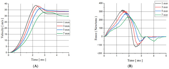
Figure 3.
(A) Velocity of the projectile, (B) force acting on the projectile.

Table 1.
Solenoid coil turns, capacitance, and increases in the launcher velocity in simulation.
Finally, the muzzle velocity is higher when the decreases in velocity are smaller. In other words, the trigger position affects the shape of the electromagnetic force received by the projectile, and accordingly, the shape of the projectile acceleration varies.
Thus, the projectile position is a key design factor that affects the overall performance of a coil gun. In particular, in a multi-stage coil gun system, the discharge system must be designed to be capable of controlling the electric circuit according to the position of the moving projectile because when the high-speed moving projectile reaches the intended position, the next stage of the coil gun must be in operation. Before the fabrication of coil gun prototypes, a coil gun system was designed using simulation. The system design involved finite element analysis using the electromagnetic analysis program ANSYS Maxwell. A multi-stage coil gun system with three stages and a final velocity of 63 m/s was used. Table 1 shows the coil winding and capacitance of the simulated coil gun.
The charging voltage of the capacitor was set at 400 V. The three-stage coil gun design showed a decrease in the winding amount and capacitance when the number of stages increased because the initial launcher velocity of the projectile increases with the higher stages. For efficient acceleration according to the increased initial velocity, the cycle of the RLC function should be shortened so that the discharge time of the capacitor decreases. Accordingly, the coil gun was designed with fewer turns of the electromagnetic coil and lower capacitance of the solenoid coil to reduce the resistance of electric circuit and inductance.
3. Charging Electric Circuit of Gun System
The electric circuit to charge the capacitor requires a booster converter step-up circuit to apply high voltage according to the capacitor’s capacitance. Moreover, for the multi-stage system, each stage has as many capacitors as the number of the stage, and the capacitors in each stage must operate independently once charged. In this study, a capacitor with a charging voltage of 400 V was used with a circuit for charging the capacitors in a three-stage coil gun system. We fabricated a charging device using a relay and a booster converter designed to simultaneously charge all capacitors through the capacitors connected prior to charging. The aim of this design was to reduce the difference in charge and to make charging control easier. The relay in the charging device was designed to physically bind the capacitors in each stage together when charging. Figure 4 illustrates the charging device used in the experiment.

Figure 4.
The charging device of a three-stage coil gun.
The operational sequence of the charging device is as follows: connecting the capacitors of the one-, two-, and three-stage coil guns by operating the relay, applying 400 V DC power to the booster converter to charge the capacitors, and turning off the relay power to complete the charging procedure once the capacitors are fully charged. The grade of the relay should be selected after considering the capacitor charging voltage to prevent damage to the relay device. The booster converter should output a higher voltage than the target charging voltage. The circuit in Figure 4 can also be used to configure a charging device for a coil gun capacitor. Figure 5 shows a prototype of the charging circuit used in our experiment.
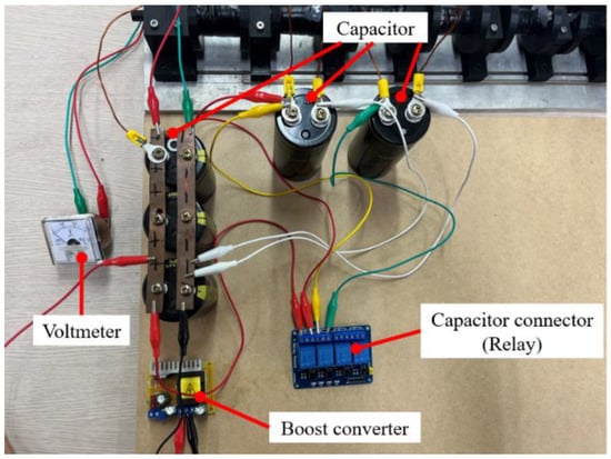
Figure 5.
The prototype of the charging circuit for the coil gun capacitor.
4. Discharge Circuit of a Multi-Stage Coil Gun System
4.1. Discharge Control Method Using a Photointerrupter
The first method proposed in this study is the direct detection of a projectile using a circuit with an infrared light-emitting diode (LED) and a phototransistor. As it entails the direct detection of a projectile, it is more apt to use a photointerrupter circuit by configuring the projectile to pass between an infrared LED and a phototransistor than to use a photodeflector circuit to detect reflected light. Figure 6 illustrates how to fit a launch tube for projectile detection using phototransistors with infrared LEDs.

Figure 6.
Configuration of a launch tube, infrared LEDs, and a phototransistor.
It is recommended that the launch tube be fabricated with an opaque material to prevent the dispersion of light output from infrared LEDs and to reduce the operating error. A photointerrupter circuit should output the SCR operation signal when a projectile is detected—that is, when the light emitted from the infrared LEDs does not pass through the phototransistor. Photointerrupter circuits must operate in a way that goes against the properties of a phototransistor, which converts light into power. Therefore, a circuit to be used as a photointerrupter needs to be used to fit this logic.
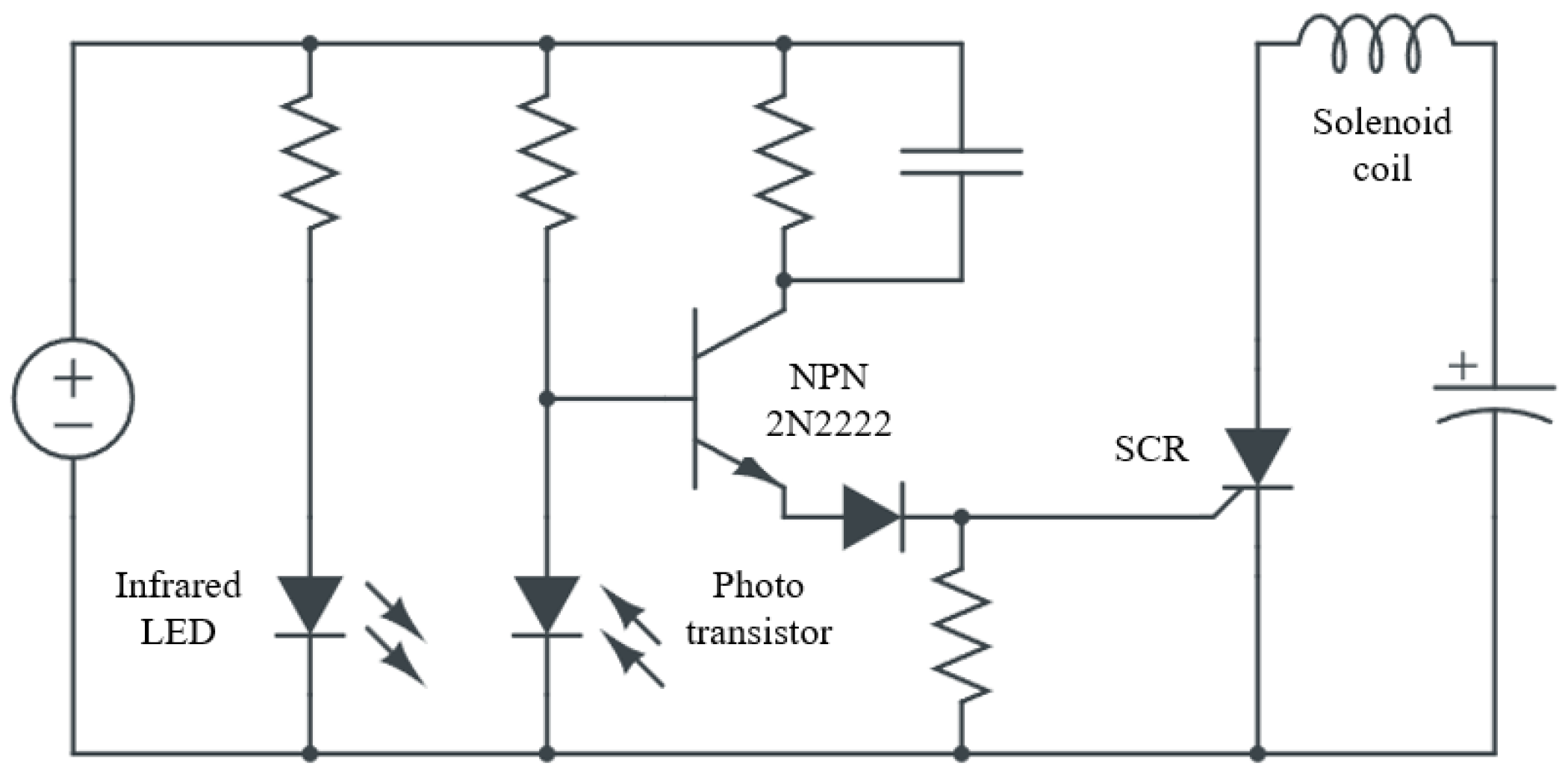
Photointerrupter circuits can be used easily with an open-source controller such as an Arduino. However, when using an Arduino to configure a discharge control circuit, its control signal output may be lower than the SCR’s operating current. Therefore, an additional circuit for amplifying the control signal may be required. In this study, a photointerrupter circuit that can independently operate with only an external power supply along with the capability of SCR operation was used. Figure 7 shows the SCR discharge control circuit with a photointerrupter.
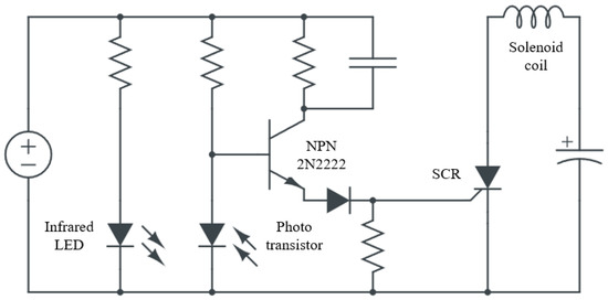
Figure 7.
Schematic of the photointerrupter discharge control circuit.
The discharge control circuit receives 12 V DC power, operates devices such as LEDs and transistors, and supplies the current to operate the SCR. The circuit requires an NPN transistor, and a 2N2222 transistor was used in this study. The resistance value should be determined according to the LEDs, phototransistor, and DC power supply voltage used in the circuit. SI5312-H was used as the infrared LED used in the experiment, and ST-5811 was used as the phototransistor. Based on the circuit diagram, a prototype of the discharge control circuit was fabricated for use in the experiment. Figure 8 shows the prototype used in this study.
Figure 8.
Prototype of the discharge control circuit.
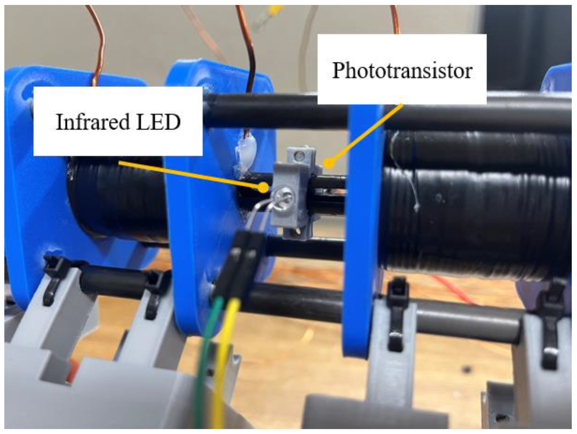
The infrared LEDs and phototransistor should be attached to the launch tube as shown in Figure 6 and fabricated to allow the adjustment of the position of the sensors. This is because even the optimal value of the trigger position obtained through simulations can be different from that in the experiment. Unlike in a simulation, during the experiment, the projectile is not located in the center of the launch tube, and friction exists between the projectile and the launch tube. Moreover, even when coil winding in the simulation and the experiment is same, the inductance and resistance values are different. Therefore, in the experiment, launch tests should be conducted based on the trigger position calculated in the simulation while adjusting the position of the projectile during operation of the coil gun. Figure 9 shows the discharge control circuit in the experiment with a launch tube installed.

Figure 9.
Installed launch tube with infrared LEDs and phototransistor.
Sensors should be installed to face each other and send out SCR control signals when the projectile moves through and blocks the light. Because the sensors must directly detect the projectile, the launch tube needs to be installed as shown in Figure 9. As the launcher velocity increases, the discharge position of the projectile moves farther away. Therefore, coils should be sufficiently spaced to secure the distance between sensors.
4.2. Discharge Control Method Using Delay
The second discharge control method proposed is a method used in a conventional coil gun system: registering a certain amount of time delay until the projectile reaches the intended position between the coil gun operations. The delay time is determined by calculating the time required for the projectile accelerated in the first stage to reach its discharge position in the next stage of the coil gun considering the trigger position. Once the projectile reaches the position where it needs to be accelerated for the next stage, it sends out an SCR operation signal to activate the coil gun circuit. This method requires a digital output device to send out the current to operate the SCR based on time settings.
In this study, an external switch input activates the single-stage coil gun with no delay, the second-stage coil gun after a delay of 2955 μs, and the third-stage coil gun after 1860 μs. Discharge control signals are sent out using an Arduino, an open-source development tool. The Arduino code used in the experiment is attached as an appendix.
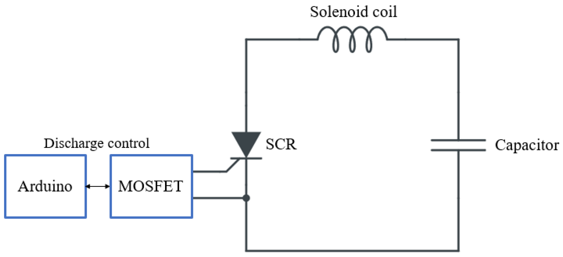
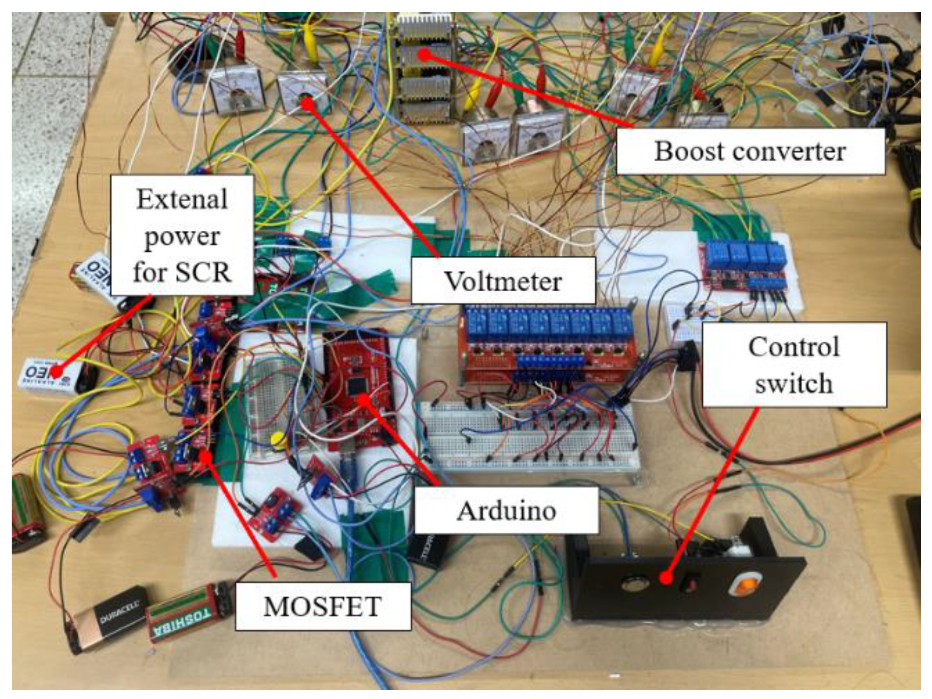
The delay values should be calculated according to the projectile position derived from the simulation considering the distance between the coils and the launcher velocity in each previous stage. The experiment was conducted based on the calculated delay values, which were adjusted to generate the maximum velocities. Because the output voltage of the Arduino is insufficient to operate the SCR used in this study, a method to amplify the control signal is required. Therefore, an amplification circuit was used using a metal oxide semiconductor field-effect transistor (MOSFET) device and an external power source. When the Arduino sends out a control signal, the MOSFET device that receives the signal connects the external power source and the SCR to activate the system. Figure 10 shows the discharge control circuit with the Arduino and the MOSFET device, and Figure 11 presents the configuration of the discharge control circuit and the SCR.

Figure 10.
Schematic of the discharge control circuit with Arduino and MOSFET.

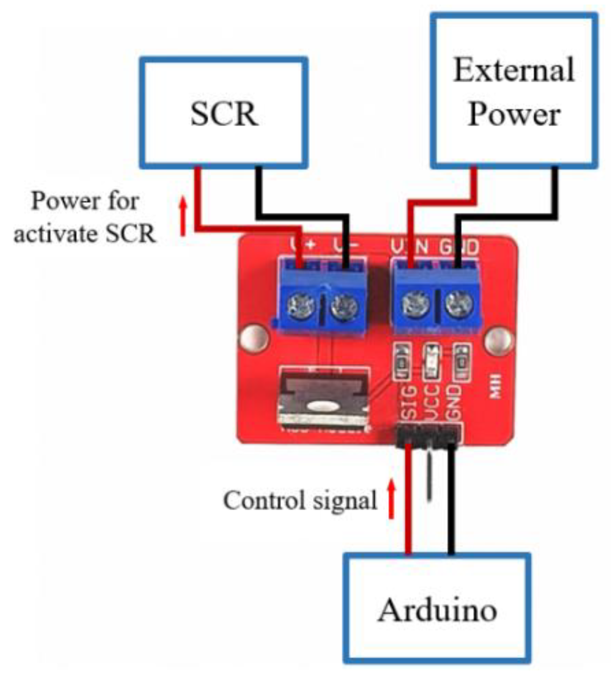
Figure 11.
SCR-MOSFET switch circuit configuration.
MOSFET switches were used in the second and the third stages, and a 9 V battery was used as the external power source for each MOSFET switch. A discharge circuit was used at each stage to prevent damage to the entire circuit during the experiment. In the event of damage, the experiment could be resumed by replacing only the damaged circuit. In addition to the method used in this study, a discharge system can be constructed by amplifying a signal using a transistor. However, this may require the additional configuration of a freewheeling diode circuit to prevent back electromotive force from being generated in the coil gun circuit, which can cause circuit damage.
A freewheeling diode circuit comprises a diode in parallel with the solenoid coil and in the opposite direction of the capacitor to eliminate the back electromotive force generated by the inductor. Figure 12 presents the coil gun’s freewheeling diode circuit. When configuring a coil gun circuit to cut off current in the middle of operation using an insulated gate bipolar transistor (IGBT) instead of an SCR, a freewheeling diode circuit must be used to prevent damage to the coil gun circuit.

Figure 12.
Coil gun circuit with freewheeling diode.
5. Fabrication and Experiment
Coil gun circuits were fabricated, and the coil gun’s launcher velocity was experimentally measured. Figure 13 shows the experimental environment, and Figure 14 shows the discharging device of the coil gun system.
Figure 13.
Experimental environment for the velocity measuring equipment.

Figure 14.
Discharging circuit of the coil gun system.
The maximum velocity was not obtained from the two coil gun systems at the discharge position of the projectile derived from simulations, so adjustment of the discharge position was required in both systems. For the delay-type discharge control circuit, this adjustment was made using the delay time. For the photointerrupter circuit, the positions of the infrared LEDs and phototransistor sensors were adjusted to measure the launcher velocity. While adjusting the positions, we recorded the delay values and sensor positions at which the maximum velocities were obtained. For the two adjusted coil gun systems, the launcher velocities were the same within the measurement range. Table 2 shows the maximum muzzle velocity when using the two-stage coil only and when using the three-stage coil gun.
Table 2.
Results of the measurement of launcher velocity of the three-stage coil gun.
The differences between the simulation and experimental results of the two models were identical. The differences were attributable to the experimental models having projectiles off the center of the launch tube and the friction between the projectiles and the launch tube. Moreover, the inductance of the solenoid coil calculated in the simulations was different from that of the solenoid coil used in the experiment. Table 3 lists the velocities of the launch experiment with the two coil gun systems. Following the final adjustment, 10 launch experiments were conducted, and the errors in the operations were compared. Regarding velocity measurements, the experiment was performed with the setting in which the maximum velocity was obtained with no changes in the delay time or the position of the optical sensors.
Table 3.
Final velocities of the three-stage coil guns with control by delay and optical sensor.
During measurement, more errors were observed in the delay-based discharge control circuit than in the photointerrupter-based one. Moreover, the differences in the launcher’s muzzle velocity were greater when using the delay-based method than when using the sensor-based method. Errors in operability occur for reasons other than those described above, such as recoil during launch. In the delay method, when an error occurred in the second stage, it affected the acceleration in the third stage, and the overall speed of the projectile decreased. If a coil gun has more than three stages, and error due to recoil occurs because the muzzle velocity is high, the acceleration in the next stage is affected. With stacking errors in each stage, the total error in launch velocity will be significant.
In contrast, the photointerrupter-based circuit showed little error in operability. Even in the event of vibration due to recoil when the coil gun is fired, the error has little effect on the launcher velocity because the launch tube and the fixed sensor move together. However, space is required for the sensors, and higher launcher velocity requires more space for the sensors.
6. Conclusions
We proposed two discharge methods for reduced multi-stage coil gun systems. Both discharge methods required adjustment of the discharge position for the maximum launch velocity at each stage.
The proposed charging device has the advantage of small differences in the charging amount depending on the capacitor used. Based on the justifications provided in this paper, the charging device can be utilized as the capacitor charging device in a coil gun system with three or more stages. Two methods have been proposed for the discharging circuit, and an appropriate circuit can be selected for the coil gun system of interest based on the characteristics of the two circuits.
The optimal discharge positions were obtained using finite element analysis without friction between the projectile and the launch tube. Moreover, in the simulation, there is wind drag, and the projectile is not located at the center of the launch tube, so the mechanical force received from the electromagnetic coil in the experiment may be different than that in the simulation. Furthermore, error arises from the difference in the resistance and inductance values of the solenoid coil designed in the simulation and the prototype of the solenoid coil with an actual coil. Consequently, adjusting the discharge position of the projectile is necessary to obtain the maximum velocity in both discharge methods.
Velocity measurements showed that the frequency and magnitude of errors were greater in the delay-based discharge control method than in the photointerrupter-based method. The delay-based method does not require the fabrication of a launch tube, but any errors such as those that occur due to recoil during launch affect the acceleration in the next stage. This results in errors stacking up and an overall decrease in performance as the number of stages increases. The photointerrupter-based method addresses the issue of these errors, but it requires the fabrication of a launch tube to install the sensors as well as space for them. Therefore, the coil gun is longer than one with the delay-based method with the same number of stages.
To reduce the resultant errors in the delay-based control system, a controller that sends out control signals that are more precise than those by an Arduino must be used. In a photointerrupter system, the LED light guide must be processed so that the infrared rays entering the photointerrupter are not dispersed, and a phototransistor with a narrower viewing angle than that used in this study is recommended. Moreover, it is important to secure the coil gun model in place to reduce the error due to recoil during firing and fasten the photointerrupter sensor attached to the launch tube in a delay-based control method.
In conclusion, the photointerrupter-based control circuit with smaller operation errors is likely to be more fitting for a reduced coil gun system. Moreover, the charging circuit and discharge methods presented are fully capable of being used in a multi-stage coil gun system with more than three stages. The discharge methods to fit the target final launcher velocity and the number of stages may be used alone or in combination based on whether a launch tube is fabricated and the overall size of the experimental model.
Author Contributions
Conceptualization, S.K.; Data curation, S.K.; Formal analysis, S.K.; Funding acquisition, J.K.; Investigation, S.K.; Project administration, J.K.; Resources, J.K.; Software, S.K.; Supervision, C.J. and J.K.; Validation, S.K.; Visualization, S.K.; Writing—original draft, S.K.; Writing—review and editing, C.J. and J.K. All authors have read and agreed to the published version of the manuscript.
Funding
This research was funded by the National Research Foundation of Korea (NRF) funded by the Korean government (MSIT) (no. 2022R1A2C1005357).
Institutional Review Board Statement
Not applicable.
Informed Consent Statement
Not applicable.
Data Availability Statement
Not applicable.
Conflicts of Interest
The authors declare no conflict of interest.
References
- Meinel, C. For love of a gun. IEEE Spectr. 2007, 44, 40–46. [Google Scholar]
- McNab, I.R. Launch to space with an electromagnetic railgun. IEEE Trans. Magn. 2003, 39, 295–304. [Google Scholar]
- Fair, H.D. Progress in electromagnetic launch science and technology. IEEE Trans. Magn. 2006, 43, 93–98. [Google Scholar] [CrossRef]
- Kaye, R.J. Operational requirements and issues for coilgun EM launchers. In Proceedings of the 2004 12th Symposium on Electromagnetic Launch Technology, Snowbird, UT, USA, 25–28 May 2004; IEEE: Piscataway, NJ, USA, 2004; pp. 59–64. [Google Scholar]
- Doyle, M.R.; Samuel, D.J.; Conway, T.; Klimowski, R.R. Electromagnetic aircraft launch system-EMALS. IEEE Trans. Magn. 1995, 31, 528–533. [Google Scholar]
- Patterson, D.; Monti, A.; Brice, C.; Dougal, R.; Pettus, R.; Srinivas, D.; Dilipchandra, K.; Bertoncelli, T. Design and simulation of an electromagnetic aircraft launch system. In Proceedings of the Conference Record of the 2002 IEEE Industry Applications Conference, 37th IAS Annual Meeting (Cat. No. 02CH37344), Pittsburgh, PA, USA, 13–18 October 2002; pp. 1950–1957. [Google Scholar]
- Ram, R.; Thomas, M.J. A Novel Technique to Arrest the Armature Capture Effect in an Induction Coilgun. IEEE Trans. Plasma Sci. 2022, 50, 3334–3340. [Google Scholar] [CrossRef]
- Ram, R.; Thomas, M.J. Developmental Studies on a Two-Stage Coilgun. IEEE Trans. Plasma Sci. 2022, 50, 3318–3325. [Google Scholar] [CrossRef]
- Camp, J.T. Optimizing Coilgun Geometry to Maximize Efficiency. IEEE Trans. Plasma Sci. 2022, 50, 3816–3823. [Google Scholar] [CrossRef]
- Zhou, J.; Liu, T. Physical analysis and optimization of electromagnetic coilgun launch systems. Am. J. Phys. 2019, 87, 894–900. [Google Scholar]
- Kim, S.J.; Kim, J.H. Control of discharge time using physical contact in a two-stage coil gun. Adv. Mech. Eng. 2019, 11, 1687814019877082. [Google Scholar] [CrossRef]
- Kim, S.M.; Kim, J.H. An Electromagnetic Circuit Design to Improve a Multi-Stage Coil-Gun’s Energy Conversion Efficiency. Appl. Sci. 2022, 12, 8942. [Google Scholar]


Disclaimer/Publisher’s Note: The statements, opinions and data contained in all publications are solely those of the individual author(s) and contributor(s) and not of MDPI and/or the editor(s). MDPI and/or the editor(s) disclaim responsibility for any injury to people or property resulting from any ideas, methods, instructions or products referred to in the content. |
© 2023 by the authors. Licensee MDPI, Basel, Switzerland. This article is an open access article distributed under the terms and conditions of the Creative Commons Attribution (CC BY) license (https://creativecommons.org/licenses/by/4.0/).