1. Introduction
Software product line engineering (SPLE) [
1,
2,
3,
4] enables the rapid production of software products that satisfy custom needs through the reuse of core software assets. This technique is widely used in industry to achieve a rapid response to market changes.
The key issue in software product family engineering is how to manage variability and reuse core software assets on that basis. Software product line variability modeling is the key technology for variability management, and it is an important technique for domain analysis. By examining the commonality and variability of the components in the system, the corresponding product family model is established using abstraction and selection methods. Feature-Oriented Domain Analysis (FODA) [
5] is a generic approach to modeling variability in domain analysis. Subsequent studies have investigated the domain analysis method, Feature-Oriented Reuse Method (FORM) [
6], based on the FODA method. However, these methods stay at the feature level description and cannot analyze the internal structure of the relevant features.
Some approaches try to enhance the understanding of the feature model by describing the function of the features. The functional role of the features in the feature model is observed during the description. Such approaches help to improve the quality of the feature model during the analytical modeling phase of the product. However, these researchers used informal methods in the analysis process, resulting in the inability of using computers to assist in the analysis for efficiency. Feature specifications written using natural language may suffer from contradictions, ambiguities, and incompleteness.
Formal methods have been introduced to solve the problems caused by the use of informal methods in the requirements analysis phase of product family feature modeling. Some researchers [
7,
8] chose to use Abstract Behavioural Specification (ABS) and UML language to describe the internal structure of the features. The use of formal specification language enables the consistency and completeness of the specification to be checked during the domain analysis phase. Additionally, the formal specification can be transformed into target software according to rules and checked using computer-assisted methods, which reduces problems caused by human factors and improves the quality and reliability of the product family model. However, these works formalized the initial feature model for each feature without considering the connection between the feature model and the feature specification.
According to our investigation and practical experience [
9,
10], we found that the feature model is likely to undergo the necessary changes during the clarification of the feature. In-depth analysis of features using formal methods often reveals consistency problems with feature models, which suggests that variability analysis and feature requirements clarification processes are related and should not be considered separately. Although there have been studies considering the correlation between the two, there is still a lack of effective methods to obtain product family models taking into consideration the relationship between analytical feature modeling and feature specification.
In summary, current software product line engineering faces a number of dilemmas. When extracting specific products from large product line feature models, similarities and functional uncertainties are found between some functional scenarios. For example, the same set of inputs may cause completely different outputs through two functional modules. This is because the analysis of product family feature models is not precise enough, and the acquisition of product family feature models relies on the personal competence of domain experts and lacks the means to improve model quality. There are some researchers who hope to improve the quality of the entire product family feature model by introducing formal methods to describe it. However, there is still a lack of research that describes a specific feature formally and considers its connection to the feature model.
In this paper, we propose a systematic approach to product family modeling. The method performs inconsistency checks during the formalization of each feature in the given initial feature model, pushing the evolution of the feature model and feature specification, and finally obtains an internally consistent product family model. The method formalizes the specification of each feature on the basis of an initial feature model. Moreover, the consistency of feature specifications with the feature model is checked during the formalization of features. When an inconsistency is detected, a relevant operation is performed to promote the evolution of the feature model. The approach consists of two key techniques: a template-based modeling approach for feature model construction and evolution and a rule-based inconsistency check approach for detecting inconsistencies between the feature specification and the feature model and giving solutions. For the template-based modeling method, each template contains two parts of knowledge: the elements needed to describe a class of feature models, and the algorithm to translate the given elements into formal description. The rule-based inconsistency checking approach is based on the consistent implementation of the formal specification. Each rule consists of a condition and an action. When the feature description and the feature model satisfy all the conditions of the rule, it indicates that there are descriptions of inconsistency, and the corresponding action hints are given to resolve the inconsistency. There are three types of consistency check rules: variable consistency rule, functional scenario consistency rule, and functional path consistency check rule.
A tool is implemented to support our approach. It guides the user in constructing and evolving the product family model. The tool detects the consistency problem between feature specification and feature model in the feature description process and automatically generates the corresponding solution according to the satisfied conditions. A specific case study is presented in the paper to illustrate how our tool works.
Our approach is language independent. We use the PFA language to describe feature models and the Structured Object-Oriented Formal Language (SOFL) [
11,
12] language to describe feature specifications. We chose PFA because it can derive the specification of the members of a product family from the algebraic specification of the abstract features of that family and the specification of each feature. We chose SOFL because it is formal and easy to use. SOFL as a formal description language combines formal methods, graphics, and a three-step approach to address the gap between formal methods and actual software development. There are already examples of specifications using the SOFL language in the actual industrial requirements analysis phase [
13].
The remainder of the article is organized as follows.
Section 2 reviews the related work.
Section 3 presents our computer-aided product family modeling after introducing the algebra of product families and the formal specification technique of SOFL.
Section 4 uses a concrete example to illustrate our approach and to briefly introduce our support tools.
Section 5 summarizes the points of the article and describes what problems we have solved so far and the direction of our work afterward.
2. Related Work
Major software product line engineering methods include software product line engineering [
2], RSEB [
3] and FAST [
4]. Variability is a core issue in the theoretical study of product line technology, and there are mainly FODA [
5], FORM [
6], and other methods. The modeling of feature variability is an important part of product family domain engineering. For example, Webber [
14] proposes a variability-based model that models variability in software product lines through four approaches: parameterization, information hiding, inheritance, and variation points. Sinnema [
15] unifies the modeling of variability across all abstraction layers of a software product family by treating variation points and dependencies as monadic relationships. Bachmann [
16] used variability features to describe the development process of a product line and proposed a unified meta-model that can represent the dependencies of variability features at different stages. In the literature [
17], a semi-automatic domain requirement modeling method for software product lines is proposed, based on the idea of separation of concerns, using feature models to represent different aspects of the features information of the products in the software product line, and the construction of the domain requirement model is realized by the comparison and combination of feature models. In [
18], the authors propose using Extensible Markup Language (XML) architecture and Extensible Stylesheet Language Transformations (XSLT) files to manage the variability of feature modeling, enabling the complete package from product line engineering to specific product implementation.
Researchers have proposed a number of proven methods around feature variability modeling, supported by tools such as Feature-IDE that have provided the industry with usable systematic modeling tools [
19]. The tool [
20] was originally built for AHEAD as an IDE that integrated all phases of feature-oriented software development, and later researchers refactored Feature-IDE into an open-source framework [
21] in order to make it available for other tools and languages. The above approach is mainly for the improvement of the product family variability modeling method and lacks a complete requirement analysis process for the product family model from the feature model to the specification of each product.
Some researchers have clarified the functions of each feature in the product family model through feature specification. In the process of feature specification, a clarification of the feature model is provided. In [
22], the authors analyze feature functionality from the perspective of functional interactions, a process that achieves intrinsic functional integrity of features and reduces functional coupling. The literature [
23] proposes a combined business process analysis and feature analysis approach to assess the quality of software product family models. The literature [
24] introduces the role of feature specification through an example of automotive software product line development. The method uses the results of feature specification description to guide structured analysis and development and reduces development costs by reconstructing the product line structure through data flow and state transition analysis. These studies mentioned above used informal language in describing the feature specifications. Inconsistencies can exist between feature specification descriptions, and these are difficult to detect. A non-formal analysis approach also makes it difficult to use tools to automate the checking of problems.
Formal specifications can prevent major errors in the early stages of a software project by precisely defining operational behavior and making it easy to build the associated automated support software. There is some work that introduces formal methods into the modeling of product families in the hope of improving the quality of product line engineering models through formal methods. However, the author of this work only suggests the advantages of formal methods for use in feature modeling-centered product line approaches and does not propose a specific methodological framework. In 2011, Ina Schaefer and Reiner Hähnle [
25] presented that formal methods could overcome the limitations of current SPLE practice, ensuring high product quality while decreasing the time to market. In [
7], the author proposes a framework combining ABS with product line engineering where an adapter combines ABS micro-services with a Zotonic-based information system that automates the generation of business logic into the system. In [
8], The author presents SPL-UML, a profile for modeling variability in the UML design of software product families (SPL). An illustrative diagram enriched by information extracted from the feature model is provided to enable the differentiation of commonalities and differences of SPL. In [
26,
27], the author proposes for the first time that a more complete product line feature model can be obtained by using formal analysis for the feature modeling phase of the product line approach. The above approaches identify the advantages of the use of formal methods in feature modeling by applying them to describe feature models. The researchers hardly consider the relation between the feature model with the feature specification process to form an internally consistent product family model. In contrast, we propose a systematic approach to product family modeling that uses feature models and feature specifications to analyze product families. The feature formalization process is checked for consistency with the description of the feature model to drive the evolution of the feature model, and the feature specification is improved based on the feature model. These two processes drive each other to obtain an internally consistent product family model.
3. Computer-Aided Product Family Modeling
Our method analyzes the feature model from both abstract and concrete aspects. The requirements are first performed at the abstract level to obtain an initial feature model. Subsequently, each feature specification is described at the concrete level to facilitate the co-evolution of both by analyzing the relationship between the feature model and the feature specification, and finally to obtain a highly consistent product family model. In this approach, we use PFA to describe the feature model and the SOFL language to formally describe the features.
3.1. Product Family Algebra
Product Family Algebra (PFA) is a formal language with a mature mathematical foundation, it mainly translates it into a formal description by studying the hierarchical relationships between features and the constraints between features in the product line family model [
28], PFA is defined as a (S, +, 0, ∙, 1) quintet to describe the features in the product family feature model, and mathematically proves the given theorem, making the product family. The formalization of the feature model becomes possible.
Definition 1. A semiring is a quintuple (S, +, 0, ·, 1) such that (S, +, 0) is a commutative monoid and (S, ·, 1) is a monoid such that · distributes over + and 0 is an annihilator.
In the definition of PFA, S is the set of features. The symbol + can be interpreted as a choice between features of different products, while the symbol · is the composition or forced presence of features. 0 represents an empty product family that does not contain any features. Element 1 represents a pseudo-product family without any features.
We will use the definition of relationships and constraints between features to build templates for guiding the construction and evolution of feature models according to the definition of PFA, which does not require any knowledge of the PFA language. It is not necessary to know the PFA language to use but to select the template according to the requirement description and give the set of parameters to automatically form the PFA expressions of the pair, which will be used to build the visual display of the feature model and the subsequent consistency check. PFA uses mathematical language to describe the relationships and constraints between features and convert feature trees into concrete representations. In this way, we can describe product feature models and relationships between features mathematically.
An example of an automotive product line is given to illustrate the PFA expression.
In the definition of the feature model, features are classified into two main classes. The first class is single features, including mandatory and optional; the second class is multi-feature structure, including multiple, alternative, and or-groups. PFA describes features in the following way. In the automotive product line, including the mandatory models (roadster, SUV, truck), the optional Autopilot configuration, defined as opt-in Autopilot. When a feature can be decomposed to be represented by multiple sub-features, the correlation relationship between the sub-features needs to be considered, containing both uncorrelated multi-feature models and correlated multi-feature models. Unrelated multi-feature models are those that can be chosen arbitrarily and have no influence on each other. There are two types of correlated multi-feature models, which can be classified as or-group features and alternative features. The or-group structure means that they can be combined at will. Just like the relationship between leather, audio, and car fridge in a car product line, they can be combined in any way. Alternative features imply that one and only one feature of the group must be selected. Features have two dependent limitations. Autopilot includes automatic gearbox, which means that the automatic gearbox feature must be selected when the Autopilot feature is present. The second relationship is an exclude relationship, meaning that two features cannot exist in the same product.
3.2. SOFL
Formal specifications can overcome the limitations of current SPLE practices and ensure high-quality products while reducing time to market. Formal methods allow accurate modeling of systems and their assumed properties based on notations with strict mathematical semantics. In the last decade, formal methods and extended verification tools have migrated from the academic to the commercial world.
There are various formal languages proposed here, such as VDM [
29], Z [
30], and B [
31]. In this paper, the SOFL language [
32] is used to validate the given methodological framework because we are more familiar with SOFL. SOFL combines parts of the formal description in VDM-SL, inherits and develops the traditional data flow graph as a new graphical description, and integrates the linguistic description in Petri nets. The formal specification of SOFL uses different notations for the description of functions. The description notation includes a description of the definition and declaration of the resource and a description of the operation the case study includes the SOFL description of a feature module. The formal specification of this module contains a description of the types, variables, and processes. The definitions of the process and module of SOFL from existing studies were used in our study. Each process consists of a set of inputs, outputs, pre-conditions, and post-conditions [
32].
Definition 2. A SOFL process p is a 4-tuple (IPort, OPort, PreP, PostP) where eachis the set of input ports of p where eachis a set of input variables.is the set of output ports of p where eachis a set of output variables, PreP is the pre-condition of p and PostP is the post-condition of p.
A module consists of a set of processes, each process describes an action or operation, the processes are connected to each other through data flow, and a complex process can be decomposed into a new module for description. SOFL is based on modules as the basic unit. Each module consists of a collection of processes. The processes are connected to each other by a data stream. The process can be further decomposed into the sub-module [
32].
Definition 3. A module (CDFD) m is a tuple (P, L, D, C, T, F,) where P is a set of processes, L is a set of labels, D is a set of data store, T denotes the objects outside the system, C is the set of lower-level CDFDs for decomposing processes in m,is a set of dataflow among processes and objects, is a set of dataflow between processes and data store, anddenotes the decomposition relations between processes in m and lower-level modules.
A process can be considered as a set of functional scenarios, each process may have a set of inputs and a set of outputs. We use functional scenarios to describe one of the inputs and its corresponding output [
33].
3.3. Formalization of Product Family Models
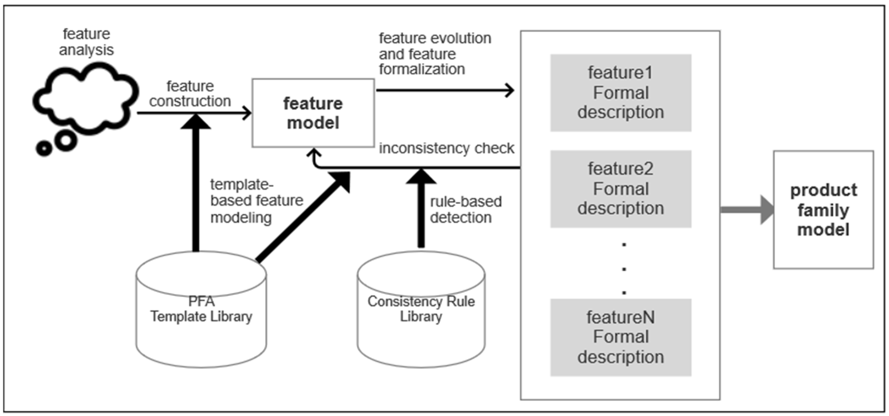
The framework of our approach is shown in
Figure 1. The approach starts with a feature analysis of the target domain, and the initial feature model described by PFA is constructed with the support of the PFA template library. Once this feature model is obtained, a formal description of each leaf feature within the feature model is performed. Its consistency with the feature model is checked by a rule-based consistency check and location method during the specification of the features. The evolution of the feature model and feature specification is driven by the corresponding actions when the conditions of the detected rule are satisfied. When inconsistency issues are no longer detected, an internally consistent product family model is obtained. There are two core techniques in this approach, template-based feature modeling approach, and rule-based inconsistency check and location approach. The PFA template library is used to support the template-based feature modeling and consists of four templates. The consistency rule library is used to support the rule-based detection approach, and the rule library consists of three types of rules: variable consistency, functional scenario consistency, and functional path consistency.
The PFA template library supports the creation and modification of feature models. Each template contains the elements required for one type of PFA and an algorithm to convert the given elements into a PFA. Templates are used by the tool to automatically generate guidelines for modeling features of product family. The requirements of the product family are guided using the templates, which are then converted into feature models by the corresponding algorithms.
The role of the consistency rule library is to support the detection of consistency between the feature specification and the feature model. Three types of rules are included in the consistency rule library. The first one is the variable detection rule, which is used to check the consistency of variable definitions. The second one is the functional scenario detection rule, which is used to check the consistency of scenarios that have the same input but result in different outputs under the same conditions. The third one is the functional path detection rule, which is used to check the consistency of functional paths.
3.3.1. Template-Based Feature Modeling
Template-based feature modeling is achieved through PFA knowledge. A PFA template library consists of a set of templates, each template is used to express a type of PFA. The PFA template consists of two important elements: one is the information needed to form the corresponding PFA, and the other is a set of rules that determine the resulting PFA expression. We use templates as a knowledge base to express the corresponding PFA relationships, and build templates in the tool to generate guidance. Templates are used for the creation and evolution of feature models. We define the PFA template as a triplet.
Definition 4. A PFA template is a triplet (N, E, exp) where
N is the name of the template
E is {elements}
exp is C→PFA expressions
N is the unique identifier of the template. E is a set of elements to be clarified, exp to satisfy the mapping relationship C→PFA expressions, it is to generate the corresponding PFA expressions for different requirements. C is the set of conditions. The PFA expressions are a set of strings, each of which is a PFA expression. PFA expressions are used for the relationships between elements in E. Individual features do not need to be connected, and multiple features are connected by symbols {·, +, opt[], (),→}.
Based on the above definition, we define four templates: multiple, alternative, or-group, and constraint. Two example templates are given for the sake of space. The multiple template definition is shown in
Table 1.
The name of the template is multiple, which is used to describe the splitting of a feature into multiple unrelated sub-features. E is the set of elements to be given in the template again, containing the parent feature, the child feature, and the type of the child feature. The sub-features name are . The types of is mandatory or optional. There are three cases of PFA expressions depending on the exp. The types of features in childE are all mandatory, the types of features in childE are all optional, and the types of features in childE are both mandatory and optional.
The constraint template definition in
Table 2:
The name of this template is constraint. This template is used to describe the constraint relationship between two features. E contains two element and . T(f) is a mapping of feature f to the {include, exclude}. The first element is the set of constrained features with the constraint type, and the second element is the constrained feature and its type. Constraint types consist of include and exclude. include means that the existence of depends on . exclude means that there does not exist a product that makes , exist at the same time.
PFA provides advanced mechanisms for describing various aspects of product families such as their relations. Only basic expressions for individual feature models are included since this paper focuses on the connection between feature model and specifications. Others will be studied in the future to enrich our modeling approach.
Templates are used for the creation and evolution of feature models. The template turns the PFA knowledge into guidance to assist the user in using PFA without understanding it. The elements within the template are then formed into PFA expressions by the corresponding algorithm (as shown in Algorithm 1) The tool then converts the PFA expression into the corresponding feature model.
| Algorithm 1: PFA generation based on templates
|
Input: Select pattern name n ∈ N
Output: PFA expressions
1: Judge the template type
2: if n ∈ {Multiple, Alternative, OrGroup} then
3: for Find all e ∈ E do
4: Get the decomposed feature f. f ∈ E
5: Display the e1, e2, …, en ∈ childE
6: input ei(i ≠ 1 … n)
7: if Get change siganl then
8: Add the new ei to the E
9: if Continue splitting ei then
10: Select n ∈ N, n = ei type
11: Repeat the above steps for adding or modifying
12: end if
13: end if
14: end if
15: if n = Constraint then
16: Get the feature f1 and T(f1)
17: Judge the T(f1) value
18: Get the feature f2
19: Add the constraint relationship of f1, f2
20: end if
21: Determine the exp of the current template
22: for Query the feature type of each e1, e2, …, en ∈ E do
23: {check exp: C→PFAex pressions}
24: f = e1 … ei opt[ei+1] … opt[en].
25: end for
26: Follow the exp.
27: for From the bottom up do
28: Replacing the high level feature using the low level features e1, e2, …, en.
29: end for
30: end for |
Give the feature f to be split, and all the elements in E. Display all sub-features of feature f in the template. After finishing the modification of f, the corresponding PFA expressions are generated according to the conditions in exp. The role of the algorithm is to convert the elements given by the template into PFA expressions, and then compose the corresponding feature models based on the PFA expressions.
3.3.2. Rule-Based Detection and Location Approach
In this section, we give the rule-based approach for feature specification description and feature model consistency checking and problem point localization. Each rule contains a class of conditions that feature specification descriptions and feature models satisfy, and actions that are used to resolve inconsistencies when the conditions are satisfied. The consistency rule base provides support for the internal formal description of features and the consistency detection of feature models. The key rules are given below.
Variable Consistency Rule
In order to check the consistency problem of variables in the formalization process for each feature (definition problem, location problem, problem of variables in the process), there are three rules of this type, as shown in
Table 3. Given the process
in module
m and a variable
where
, there are two variables,
, where
,
and
,
. When the conditions in
Table 3 are satisfied, the evolution of the feature model is driven by the corresponding actions.
The first rule deals with variable definition consistency. This rule checks for inconsistencies in the definition of the same variable in a different process. The function def(v) describes the definition of v. If a variable v belonging to the set of variables V is described as different in the formal definitions of process A and process B (), the consistency principle of the formal description is violated, and the given guideline hints to change the description of v in the feature model. R(v) means that the variable v needs to be redefined.
The second rule detects variable position consistency. In process A, there does not exist an output variable that is also a process precondition variable; if it is found to exist, then the specification states that there is an inconsistency problem and the formal description of the current process needs to be modified. M(v) means that the variable v needs to be modified.
The third rule deals with the consistency of variables in the process. This rule is illustrated as follows. For each process in the module, there can be no variables that appear in the pre-condition and post-condition and do not belong to the set of input and output variables of process
A. Variables stored in the database are not subject to these conditions. We will return this variable name and automatically add it to the variable definition of the module m to which process A belongs. means join the variable to the set of variables of process .
Functional Scenario Consistency Rule
This rule is used to detect inconsistency problems that can cause more than two outputs for the same input condition. We define the consistency detection condition for functional paths as the same functional scenarios may lead to different outputs. These functional paths have the same entry point and subsequently enter different processes depending on the conditions they each satisfy., resulting in different functional paths. The consistency of the description of functional scenarios is determined by testing the consistency of the outputs of functional paths with the same entry point and different exit points.
Definition 5. A function scenario of a process p is a conjunctionwhereis the pre-condition,andare one of the guard conditions and defining conditions in the post-condition. Each guard condition is a predicate that contains no output variables and each defining condition is predicate that contains at least one output variable but no guard condition.
In one functional scenario, is called “guard condition”, which contains no output variables and satisfies , is called “defining condition”, which involves at least one output variable, and defines the expected final state of output variables. Each functional scenario defines an independent behavior.
Definition 6. denotes the set of functional paths for a functional scenario. A functional path I is a sequence:in the module m where eachandis the pre-condition of P, iff
The functional scenario path I consists of a sequence of conditions. The first node in the sequence satisfies that any variable cannot exist in other nodes when it belongs to the input of the head node. When any variable belongs to the output of the tail node, it no longer points to the input of any node. Any two nodes are connected by a data flow.
For a sequence of functional scenarios, the input condition of the starting node does not come from other nodes, and the output of the ending node is no longer used as the input of other nodes.
For each two modules
and
,
is the set of functional paths in
and
is the set of functional paths in
, a set of inputs
I. The functional scenario consistency rule is as follows:
In the module and , the presence of one set of inputs I causes that different paths in the two modules can be activated at the same time. Such a set of inputs needs to be decomposed into more than two processes. P(I) means that the set of inputs is put into a new process and add the new process to the set P.
According to functional path range detection, we give the algorithms. The Algorithm 2 first compares the expressions of the functional scenario paths, and if it is found that the initial inputs of the two paths are the same, but the outputs are different, then check the input range for both paths. The nodes of the two paths are split to obtain the C and D expressions of all their nodes, and the range of input conditions of the two paths are detected using Z3 to see if they overlap.
Algorithm 2 deals with the consistency detection of functional scenarios, and Algorithm 3 describes how to translate the given condition into an expression of Z3 and calculate the range of the input conditions. For the processing of the conditions, we use the following algorithm. First, we determine the type to which the expression of the condition belongs, parse it according to the type, convert it to a type that Z3 can recognize, and then use Z3 for range determination.
| Algorithm 2: Functional scenario condition detection |
Input: The set of all paths η
Output: Give prompts according to the triggered rules
1: for Matching the set of generated paths in the set of η do
2: Get VPreP
3: Get C ∈ η
4: Get D ∈ η
5: if two path I, J ∈ m then
6: if IVPreP = JVPreP then
7: if IVPostP ≠ JVPostP then
8: Convert C and D into mathematical expressions for range determination
9: Put the conditions on the path to Z3 format for determination
10: Derive the solution range of two path
11: if Two path ranges overlap then
12: print the warning
13: end if
14: end if
15: end if
16: end if
17: end for |
| Algorithm 3:Condition classification and processing |
Input: function scenario path l
Output: Z3 detection results and adjustment opinion
1: Put C and D from path l to set Condition
2: for int i = 0; Condition[i]; i++ do
3: if Condition[i] ∈ v⊙N then
4: Convert to Z3 statements into container
5: end if
6: if Condition[i] ∈ ⊕(v, S) then
7: if S ∈ set then
8: Read variables from set’s database
9: Convert it to N according to the specific operator
10: end if
11: if S ∈ sequence then
12: Read variables from sequence’s database
13: Convert it to N according to the specific operator
14: end if
15: Convert to Z3 statements into container
16: end if
17: if Belongs to SOFL true or false judgment then
18: if true then
19: No impact
20: end if
21: if false then
22: Path conditions are written incorrectly and return problems
23: end if
24: end if
25: Converts all expressions to v⊙N and put it in the container of Z3
26: end for |
The algorithm receives a functional path and puts all C and D in the path into an array of conditions. Each condition in the array is judged individually. Conditions belonging to type are directly converted to Z3 expressions and put into the container of Z3. If the condition is of type , further determination of its SOFL symbol type is required. According to the corresponding type, the data is read in the pre-stored database and its expressions are converted to .
The data that can be handled are shown in
Table 4. We will discuss the following cases: (a) there is only one variable involved and R(
) has the format
, where
is a relational operator and N is a constant expression; (b) there is more than one variable involved in R(
) with a format of
, where
are the constant expressions; (c) there is only one SOFL variable involved and R(
) has a format of
, where
and {S} are SOFL type data including both set and sequence; (d) more than one SOFL variable is involved in R(
) with a format of
, where
, and
are the SOFL type data such as S. Functional scenario detection rules currently support variable types of numeric types, enumerated types, and Boolean types. These types are all SOFL data types [
34]. The SOFL
set and
sequence types must be declared in the specification:
inset is used to determine if the target value is in the set,
notin is the opposite of
inset,
subset(set1, set2) is used to determine if
set1 is a subset of
set2,
get is used to obtain the value from the set,
inter(set1, set2) is used to take the intersection,
diff is the opposite of
inter,
len is used to calculate the length of the sequence,
hd is used to take the first element of the sequence, and
tl is used to take all the elements of the sequence except the head element. We extract all the conditions of the functional paths separately for determination, and we directly use the Z3 constraint solver [
35,
36,
37] to determine the range for the input for functional scenarios that meet the numerical range determination. We assign the conditions to conform to the SOFL assignment statement based on the data type and operator, and then convert them into Z3 determination conditions for comparison. If the condition is true, we will continue with the range determination, and if it is false, we will stop the current determination. The operations that can be handled for numeric data include addition, subtraction, multiplication, division, and operators such as greater than or less than. The operations that can be handled for sequence data include fetching length, fetching the beginning of the queue, fetching the end of the queue, merging the queue, and for collection, data include inserting, fetching elements of a collection, fetching the same elements of multiple collections, and fetching different elements of multiple collections.
Functional Path Consistency Rule
Based on the possible inconsistency in the declarations of functional scenarios, we give the following rules for illustrating the cases of inconsistent declarations of functional scenarios. The functional path consistency check applies to the following case. For each process p and the variable
In a functional scenario of a process, there cannot be a functional scenario in which the same input leads to two or more different outputs. If such a scenario exists, then the specification indicates that an error exists and it can be assumed that the functional scenario can be divided into two different process descriptions. The S(p) function splits process p into two new processes and , and adds them to the set P.
The Algorithm 4 first obtains all processes
p from module
m, then extracts all conjunction
from
p. If the two paths are different only in the
part, it is considered a problem. This situation means that two paths produce inconsistent outputs under the same input conditions, which violates the consistency principle. Inconsistent error hints are required at this point and should ensure that different inputs lead to different outputs.
| Algorithm 4: Single path detection |
Input: A module m and process p ∈ P
Output: path and adjustment opinion
1: for find the functional scenario path in p do
2: if path ∈ η then
3: i, j, k are the variables of path
4: if i ∈ Ci, j ∈ Dj, k ∈ Dk then
5: if Ci ˄ Dj = Ci ˄ Dk then
6: p = p1 ∪ p2
7: end if
8: end if
9: end if
10: end for |
The above three rules are our current proposed formal description of the consistency detection rules, giving some of the algorithmic ideas.
4. Case Study and Supporting Tool
To validate the proposed approach, we developed the support tool. According to our approach, the main work of the tool is divided into two modules based on the library. One is the PFA template library, and the other is the consistency rule library. The PFA template library mainly supports feature model construction and modification; the consistency rule library is responsible for checking problems in the formal description of feature behavior. We also provide a visualization interface of the feature model and a formal description window in the tool as an aid.
Our tool mainly implements the following functions:
PFA template-based feature model construction and evolution;
Description of a specific formal specification based on SOFL;
Consistency check based on SOFL’s specifications;
Consistency check problem point location and modification suggestions.
The design structure of our support tool is shown in
Figure 2. The main function of the tool is feature modeling and a feature specification description. The feature modeling relies on PFA templates, and the data of PFA templates are processed by XML to generate the corresponding feature trees, and then the features are specified, and the generated formal descriptions are stored in XML files, then checked for consistency, and resolved suggestions are given for inconsistent parts. The PFA template library and the consistency rule library provide support for feature model evolution and consistency check.
We provide the specific modeling process for the reservoir management system (RMS) software system as a way to illustrate how we integrated formal specification with feature modeling in the requirements analysis phase. The most initial RMS feature model was constructed using PFA templates (
Figure 3). The process involves the following. First, we analyze the requirements of the reservoir management system product line project, the basic functions of the reservoir include water storage and water release; they both belong to the reservoir state, then the reservoir state warning function is a mandatory function and contains two sub-modules of water storage and water release; the reservoir operation should be operated by personnel and requires a member management system; considering the different sizes of reservoirs, the product line project should be adapted to different types of reservoirs. Finally, considering that natural disasters may pose a threat to reservoirs (some reservoirs do not need this function), an optional hazard alarm function is provided. Based on the above analysis, we started to build the initial feature model using the PFA template. RMS consists of four basic features: mandatory feature MM (member management) defines the operator of the reservoir; in mandatory feature RSA (reservoir status alerts), the two inherent states of the reservoir are defined, including WS (water storage) and DTW (drain the water); mandatory feature SGM (sluice gate management) defines the management of sluice gate; optional feature DAM (danger alert management) defines the management of emergency situations, considering that some reservoirs do not have to include emergency management, so it is an optional feature. We first create a new RMS product line feature file, then select the multi-feature template, and then select the current node as RMS, then enter the name and type of the current node child node, we follow the above description to enter MM, RSA, SGM, and DAM into the template in turn, and then change the current node to RSA and then enter WS and DTW two features, at this time the initial feature model construction is complete.
The main function of RMS is to help reservoir managers handle member management, reservoir status alert management, sluice gate management, and danger alert management. Different reservoirs may have different requirements for specific systems for various reasons, so a family of products about RMS needs to be created. Based on the proposed methodological framework, we first built an initial RMS feature model as shown in
Figure 4. For the sake of observation, here we use Eclipse’s Feature-IDE [
19,
20,
21] plug-in to draw the feature model.
After finishing the initial feature model definition of the RMS system, we start the formal description of the SOFL for the RMS system, and the SOFL editor is shown in
Figure 5. This includes feature names, constants, types, variables, and sub-module declarations. For the process part, we require user input for process names, input variables, output variables, and pre-conditions and post-conditions, and for analysis purposes, we require user input for post-conditions by group (a guard condition and a defining condition). Finally, we use an XML file to store the edited data.
The feature RSA reservoir status alert is a function that provides alerts to reservoir operators according to the reservoir status as well as the external status of the reservoir. We divide it into two states: water storage and water release. The water storage specification is in
Figure 5.
The following factors are taken into account in determining the status: reservoir water level, intake rate, release rate, rainfall volume, and the number of gates opened. When all the data in the reservoir reach the storage or release warning line, the corresponding alert is given. Start the conflict detection after completing the formal description of RSA. After conflict detection on the formal description of RSA, we found that there are two functional paths (The two paths are shown in
Figure 6) in the description of the process water storage and drained the water, which has the same set of inputs that results in two different signal outputs (water storage signal and drain the water signal) in
Figure 7.
We can find that the conditions of the two paths are satisfied simultaneously when waterline = 15, inlet velocity = 25, rainfall = 3, and gate = 3, but the two paths have different outputs. This violates the functional path range detection rule of our rule library that the same input cannot exist with different outputs. Clicking on the problem prompt, the system automatically pops up a multi-feature selection template, as shown in
Figure 7. A prompt message is given in the suggestion column suggesting splitting the overlapping range into another sub-feature to complete the feature model refinement. Following the hints, we believe that there should be an intermediate state between water storage and water release, which we call the safe state, when the water level in the reservoir is in a safe state and no other cues need to be given and we split RSA into water storage, safety, and drainage. By constructing an intermediate state safety process to store the overlapping input part of the actual process, the formal description of the safety process is completed and then detected again without finding the same problem. The feature model is changed, as shown in
Figure 8.
We performed a new round of formal descriptions of the updated RSA module. In the new round of requirement description, we thought that water storage, drainage, and safety should have a status display function. In the formal description process, we added status variables in these three sub-modules at the same time, considering the practical situation that the message prompt may need to be displayed on mobile, in the formal description, we continued to add a message prompt process in RSA, and the output of the process is a status message. However, after consistency testing, we found that the state variables are named the same but defined differently, and the state message as the output of the message prompt process is not declared at the variable, which violates both of the variable consistency rules (inconsistent definitions and undeclared variables appearing in the post-condition). Based on the hints, we add an optional sub-module state display through the template for unifying the definition of state variables, and at the same time, add an optional mobile subsystem under the RMS for message notification and reservoir operations. The updated model is shown in
Figure 9.
We start by describing the gate management system SGM, which consists of two main functions opening and closing. The open function serves to select specific gates to open them. The close function does the opposite of the open function. The function focuses on the gate number, status, and success of the operation. A signal is returned to indicate the success or failure of the operation.
Based on the above description, we have a formal description of the MM and SGM in the tool as SOFL. We then perform a formal conflict detection on it. We found the variable success information in the output of the process delete and process on, which have the same variable name but with different definitions, violating the variable consistency rule, so the user is prompted to make changes to the variable definition of the MM module or change it in SGM module. By continuously cycling the above process until the conflict detection no longer finds problems, we will obtain a high-reliability feature model and the corresponding formal description. The modification of the feature model is carried out under the condition of composite specification, so it does not affect the consistency of the features.
RMS has been guided by our approach with the following changes. In the first round of checking, we found inconsistencies in the formal descriptions of the two functional scenarios of WS and DTW in the reservoir management system, with some scopes that can satisfy both functional scenarios. After extending the feature model and rewriting the feature specifications as suggested again, it was detected that the newly completed functional scenarios used some of the previous variable descriptions, but their definitions were problematic and there were some variables that had not been defined yet. At this point, two feature nodes have been expanded on the basis of the original feature model, the mandatory feature safe and the optional feature SD. In another round of testing, we found a problem with the SD feature path. The main role of SD is to notify the reservoir status to the manager. In the SD feature, there are two feature scenarios that have the same input but lead to different outputs. Based on the hints, we split the notification function into message notification and reservoir operation. RMS went through three evolutions through the above process, and a total of five inconsistencies were resolved, and the feature nodes were changed from 7 to 12.
We conducted example studies on reservoir management systems (RMS), air conditioning controller systems (ACCS), account management systems (AMS), and mobile phone products (MPP), and constructed corresponding feature models and formal specifications. The PFA expressions for each case study are given in
Table 5. The initial number of features for each product family and the final number of features after several evolutions are given in
Table 6. The RMS product family originally contained 7 features, which evolved three times to 12 features, and the ACCS product family evolved four times from 17 features to 23 features. After verification by example, we found that introducing formal specifications in the requirements analysis phase can solve the actual inconsistency problem in the analysis and effectively improve the consistency of the product family feature model.
5. Conclusions
This paper proposes a systematic approach by integrating feature models with feature specification descriptions. Feature model construction, evolution, and specification consistency checks are facilitated by each other to obtain internally consistent product family models which contain product family feature models and corresponding formal specifications. In terms of internal validity [
38], it will be difficult to avoid inconsistencies in the feature model when building a specific product after only one round of specification of the initial feature model without using our approach. After using our method, the consistency problems of variables, feature scenarios, and feature paths are excluded, and the quality of the product family model is improved. We illustrate with a few simple examples that our approach applies to product line engineering in different domains. In subsequent work, we will evaluate the computational efficiency of our approach and its applicability to large product line engineering by analyzing a large product line.
We provide a support tool that allows users to select suitable templates to build and evolve feature models without knowledge of PFA, then describe the internal structure of each feature with formal specifications based on the generated feature models, and finally perform consistency checks on the formal specification descriptions. In addition, we provide advice to solve inconsistencies by corresponding actions for the checked inconsistencies to facilitate feature model evolution and finally obtain internally consistent product family models. After four examples of practice, our approach proved to be effective in improving the consistency of the product family model. Using the approach proposed in this paper helps to obtain internally consistent product family models. The product family models obtained according to the method include feature models with feature specifications, and product-specific model specifications can be derived from the feature models and the formal language.
Our approach has some limitations identified by tool implementation and experimental analysis. First, with our approach, in order to improve efficiency and industrial usability, the tool only tests for variable consistency and path range consistency in the formal description, and ignores the presence of other conditions in the postcondition that do not meet the test specification, which may lead to some existing problems that are not detected. Second, although our tool sets the input content and formatting requirements for the formal language, it still requires a certain level of knowledge of the SOFL formal language. In future work, we will further expand the range of variables that can be supported, and will consider reducing the difficulty of using SOFL through the three-step approach of SOFL, adding other means of inconsistency detection, no longer relying only on constraint-solving tools.


