
Transient Cooling of Millisecond-Pulsed Heat Sources by a Jet Impingement Heat Sink with Metallic Phase Change Material

Abstract
:1. Introduction
2. Numerical Methodology
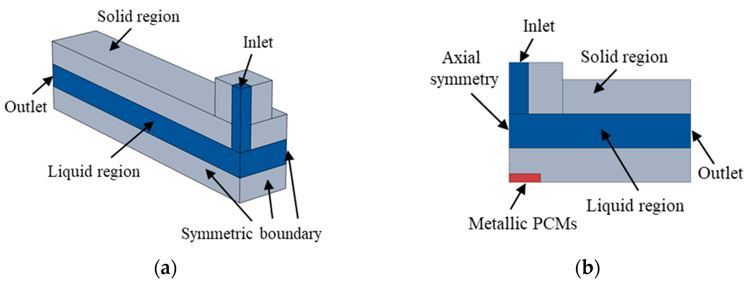
2.1. Geometry Model
2.2. Model Assumptions and Governing Equations
- (1)
- The flow and temperature fields are symmetric with respect to the geometric symmetry planes of the heat sink;
- (2)
- The cooling medium is an incompressible fluid, and its thermophysical properties are adopted at the average temperature of the inlet and outlet;
- (3)
- As the temperature of the device will not exceed 100 °C, the thermal radiation of the device to the external environment is negligible;
- (4)
- The influence of gravity is negligible;
- (5)
- The metallic PCM is assumed to be uniformly embedded between the contact surface of chips and the heat sink;
- (6)
- Convection heat transfer of the melted PCM can be assumed to be negligible due to the small thickness.
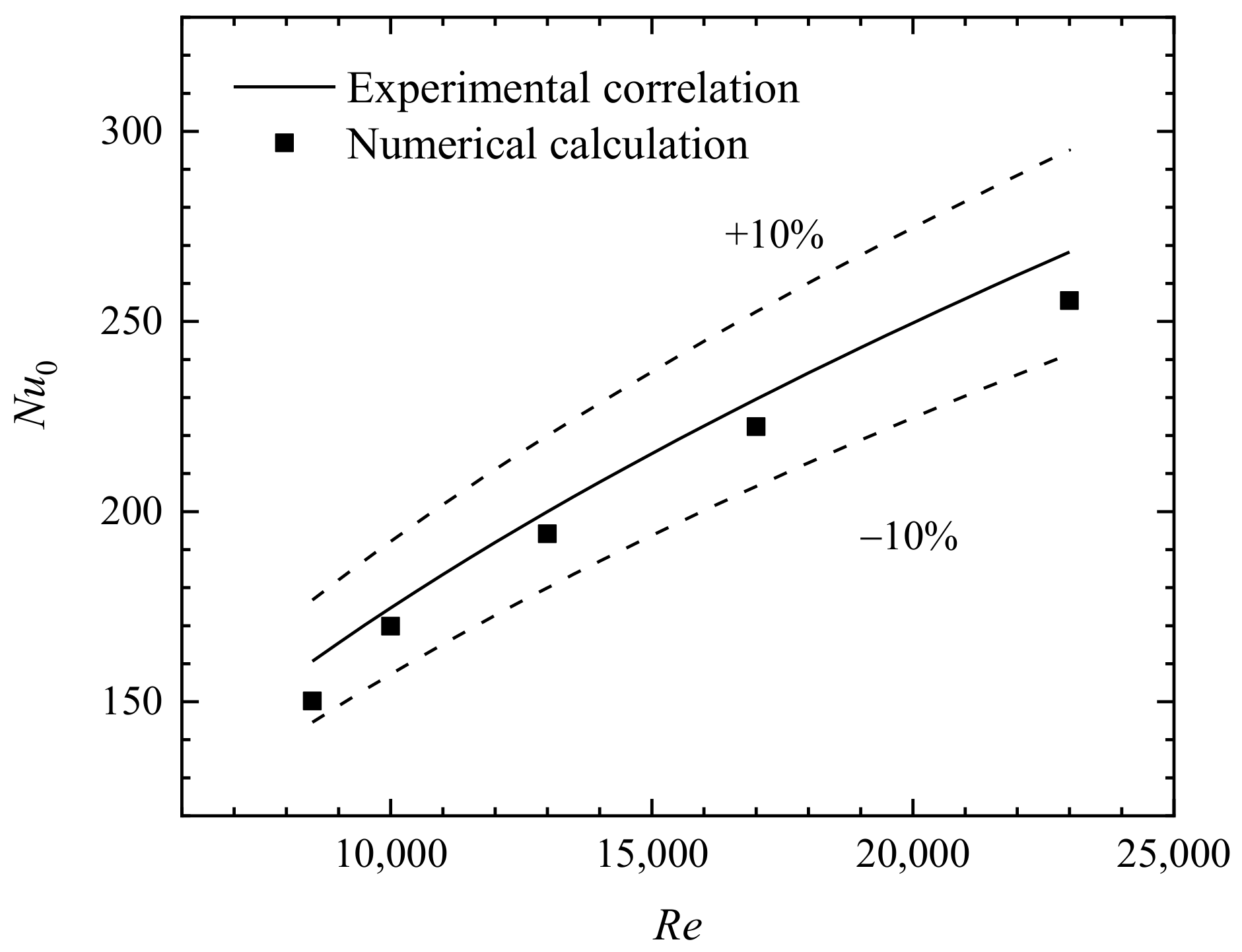
2.3. Mesh Generation and Model Validation
3. Results and Discussion
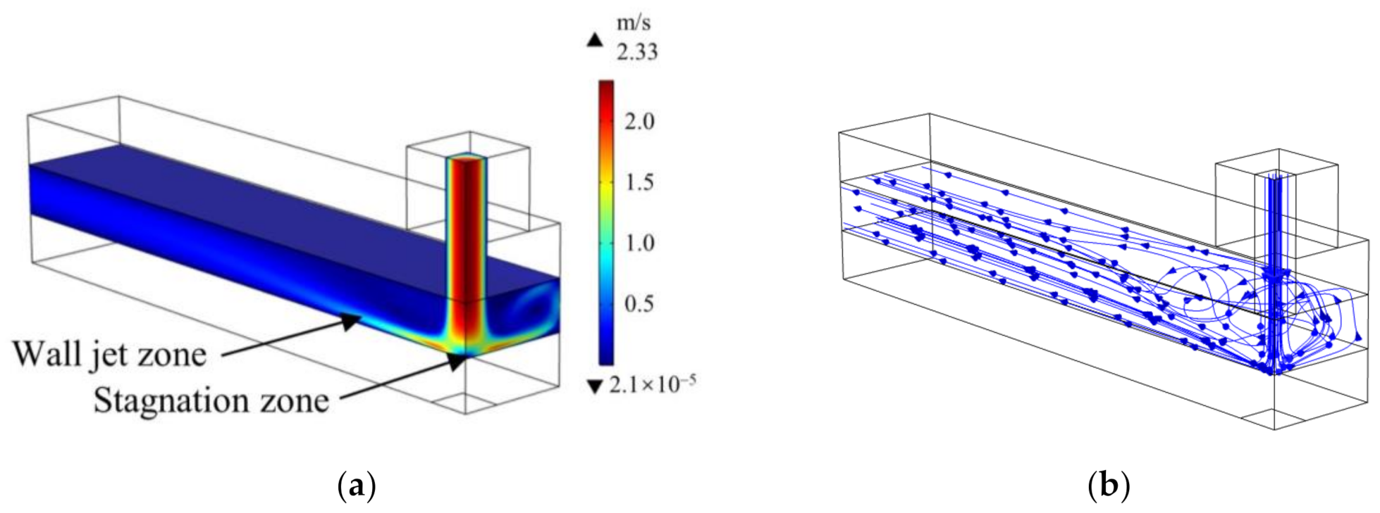
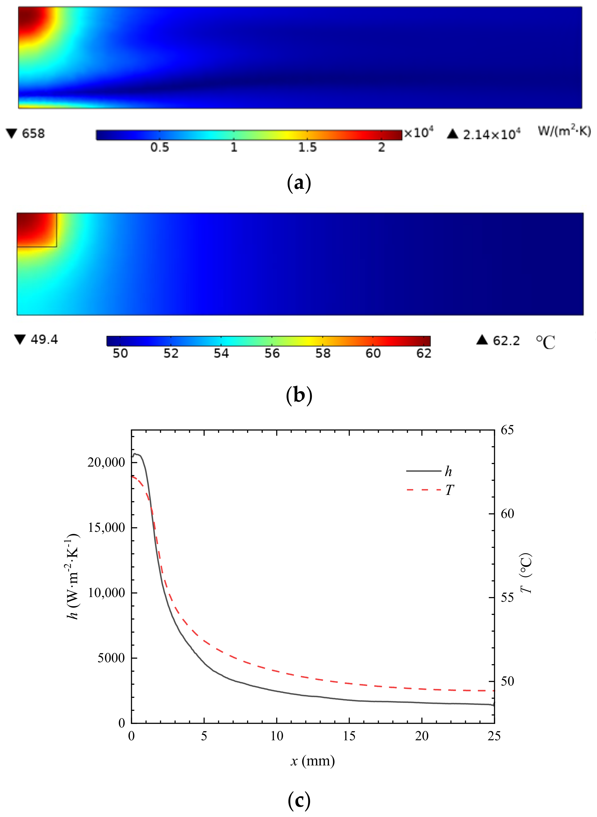
3.1. The Performance of Jet Impingement under a Constant Heat Load
3.2. Transient Performance under High Heat Flux Millisecond Pulses
3.2.1. Transient Responses under Millisecond-Pulsed Heat Sources without PCM
3.2.2. The Effects of the Thickness of the Metallic PCM Layer
3.2.3. The Effects of the Heat Pluses’ Peak Heat Flux and Duty Cycle
3.2.4. The Comparison of Thermal Contact Performance between the Metallic PCM and Thermal Silicon Grease
3.3. Comparison of the Current Study with Other Existing Numerical Studies
4. Conclusions
- (1)
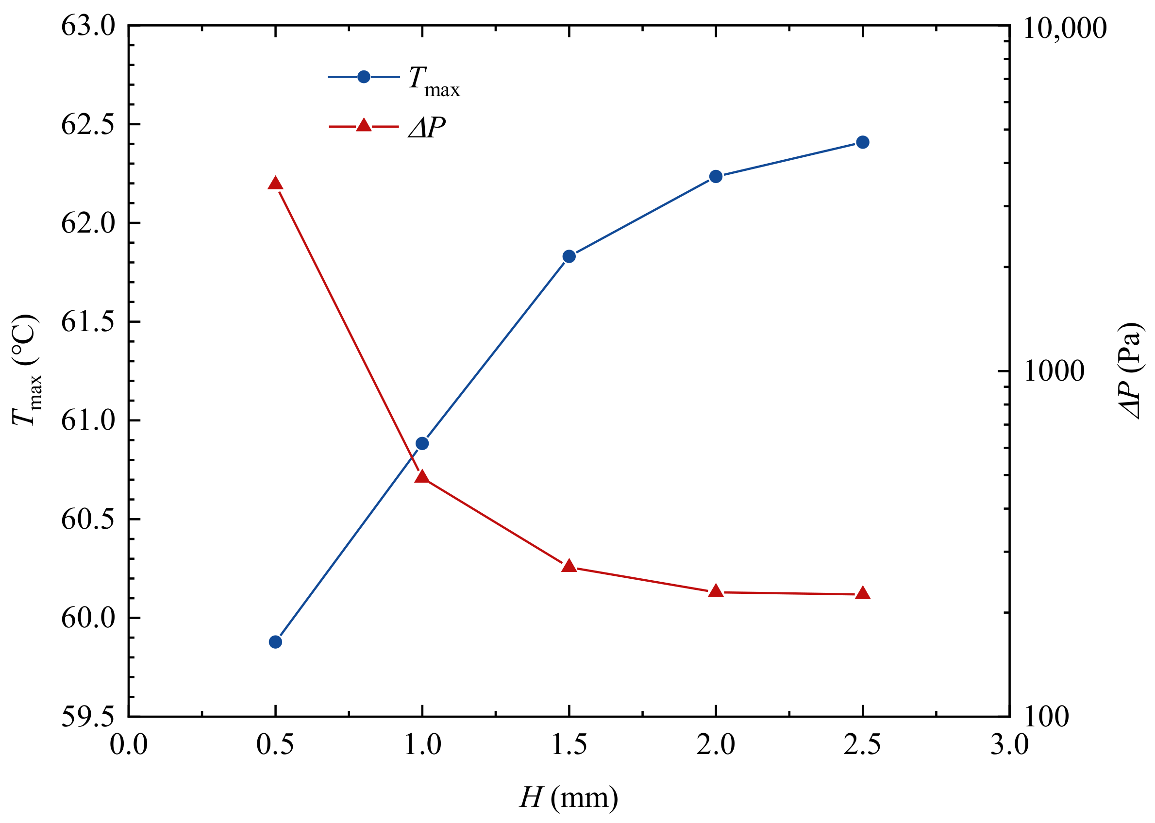
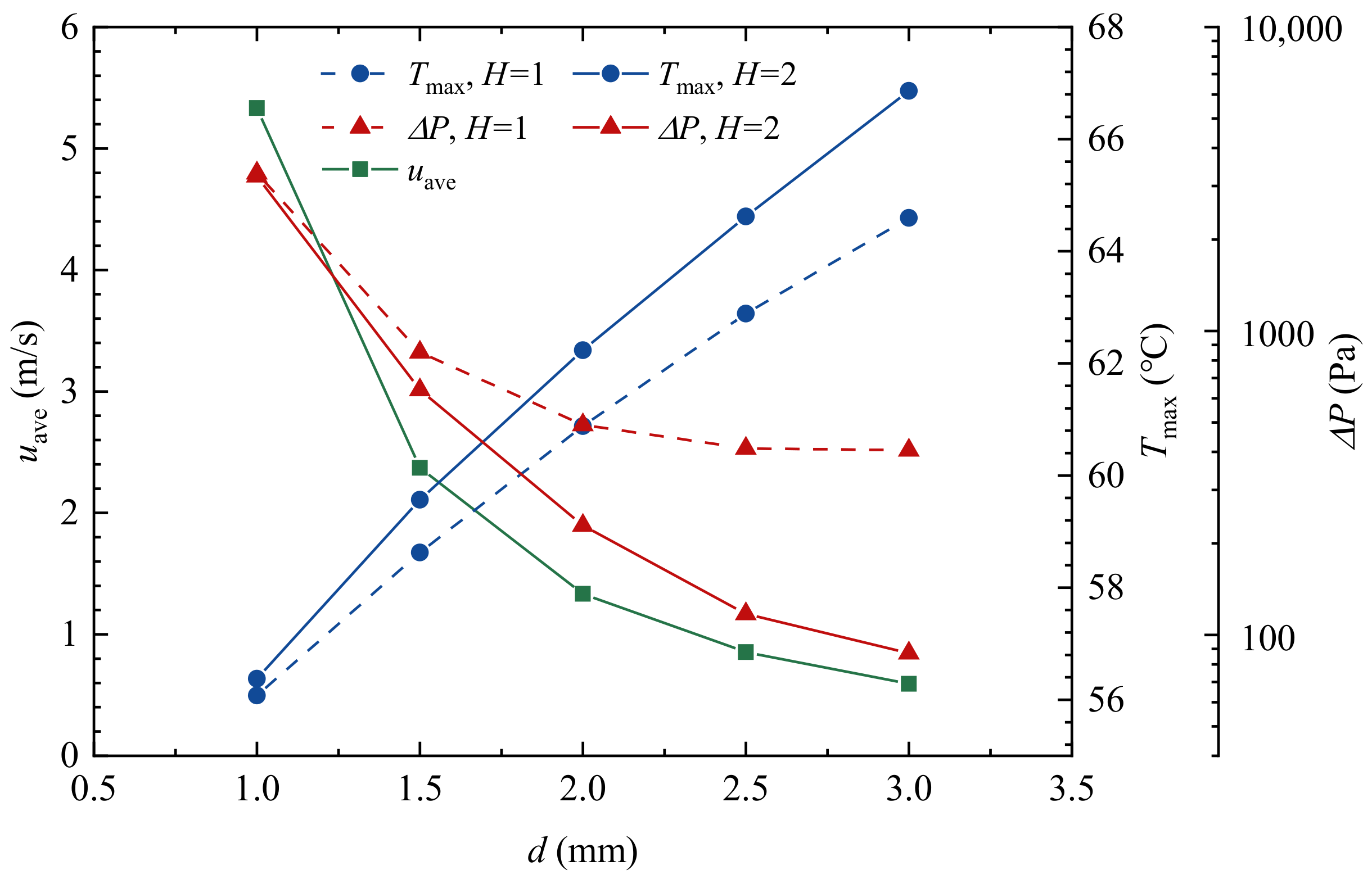
- Under the same volumetric flow rate of the cooling medium, the heat transfer of jet impingement can be enhanced with the decrease in jet diameter and jet height, but the pressure drop increases dramatically. For a jet diameter of 2 mm and impingement height of 2 mm, the maximum surface temperature on a 3 × 3.5 mm2 surface of a constant heat flux of 150 W/cm2 can be cooled to 62.2 °C with a coolant inlet temperature of 35 °C.
- (2)
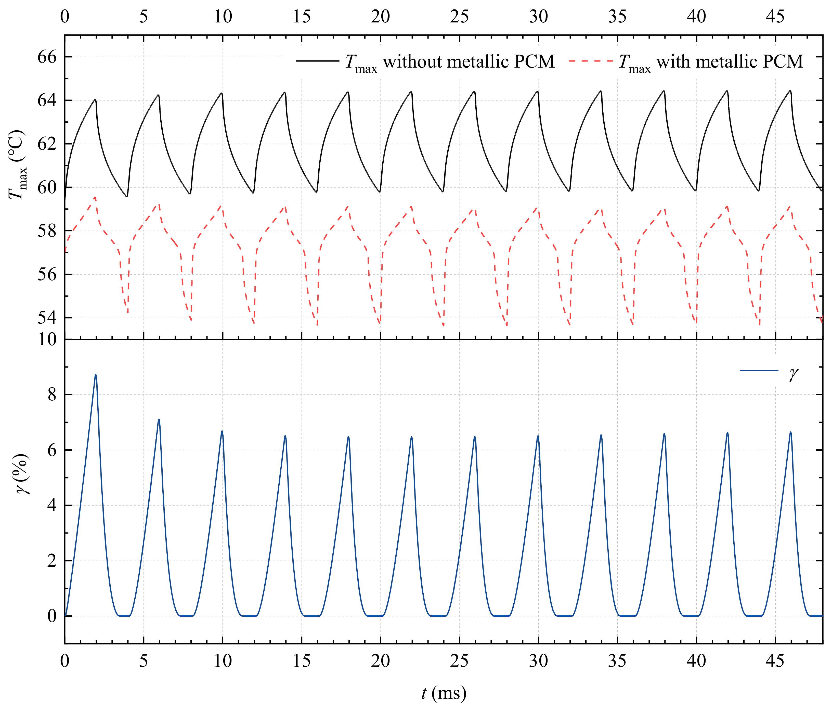
- Under the heat pulses with a peak heat flux of 600 W/cm2 and duration of 1 ms per 4 ms, the temperature fluctuates in the same period as the heat pulses, and the maximum temperature is increased to 66.9 °C for jet impingement cooling. After adding a thin layer of metallic PCM, the maximum temperature can be reduced to 61.5 °C.
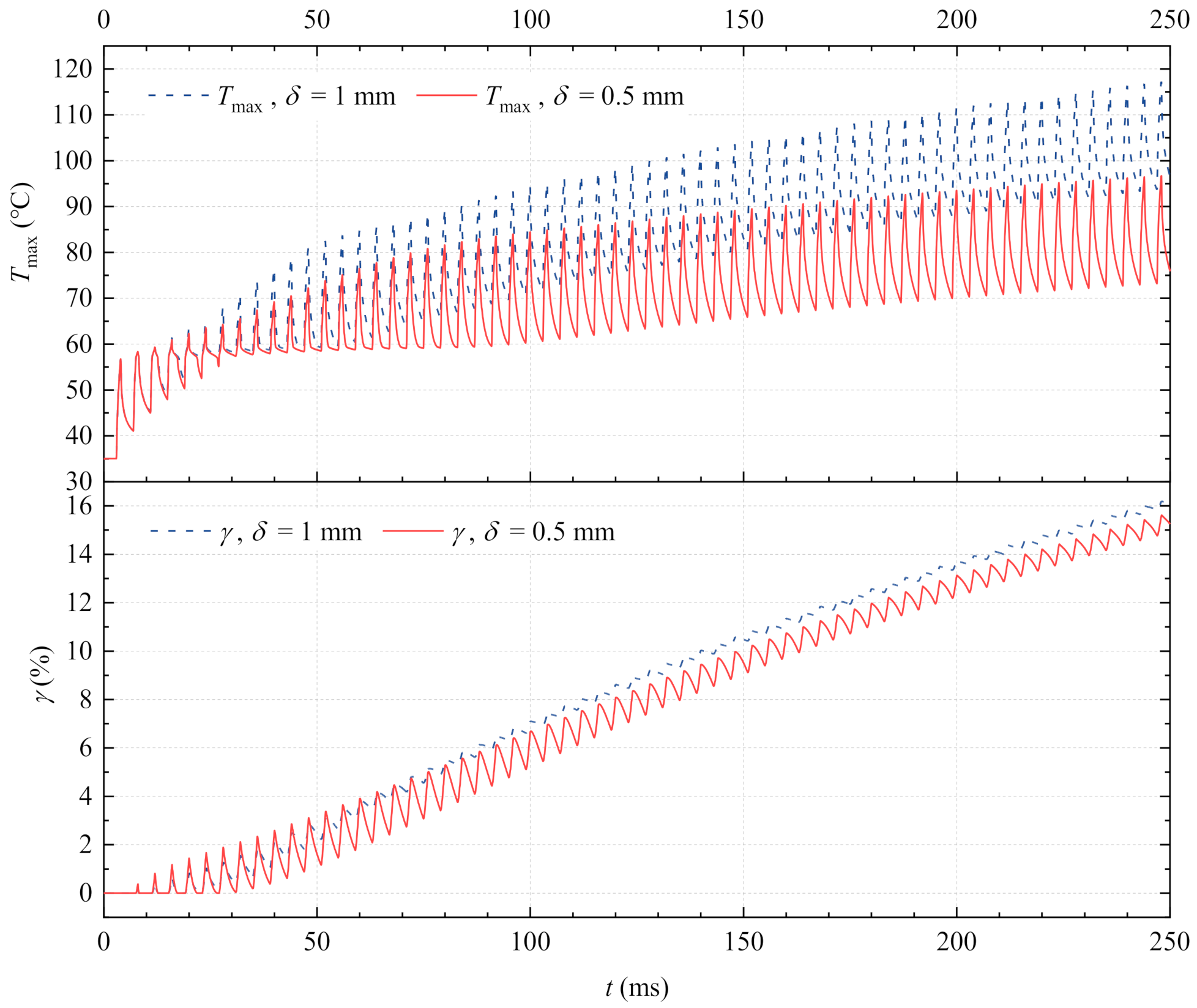
- (3)
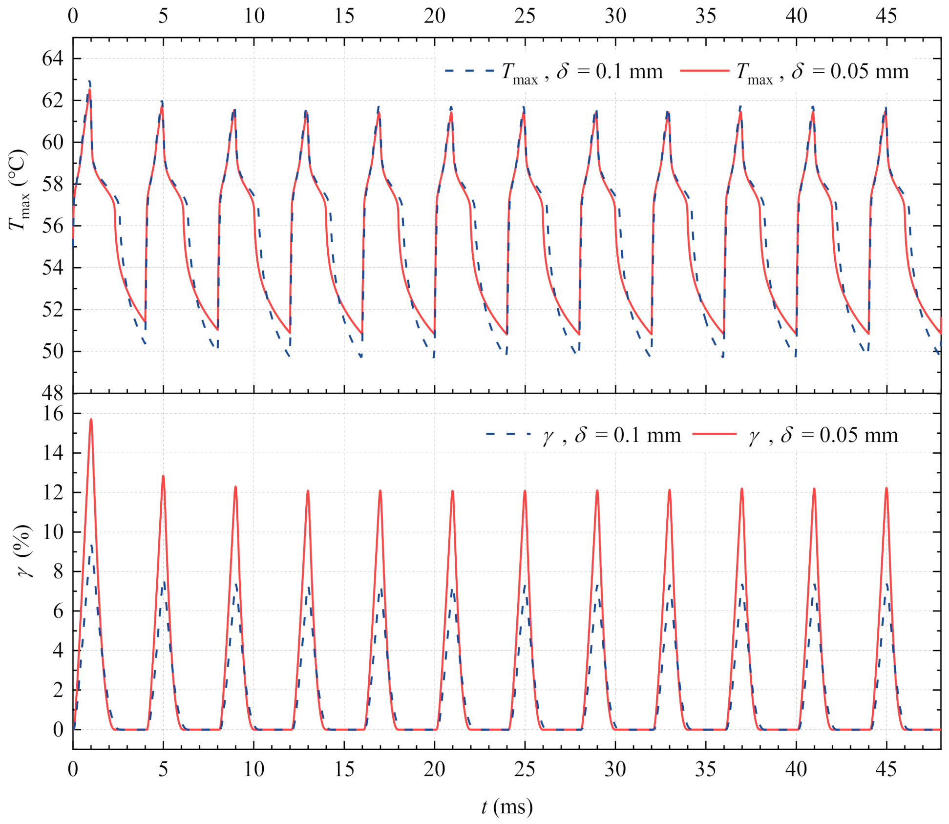
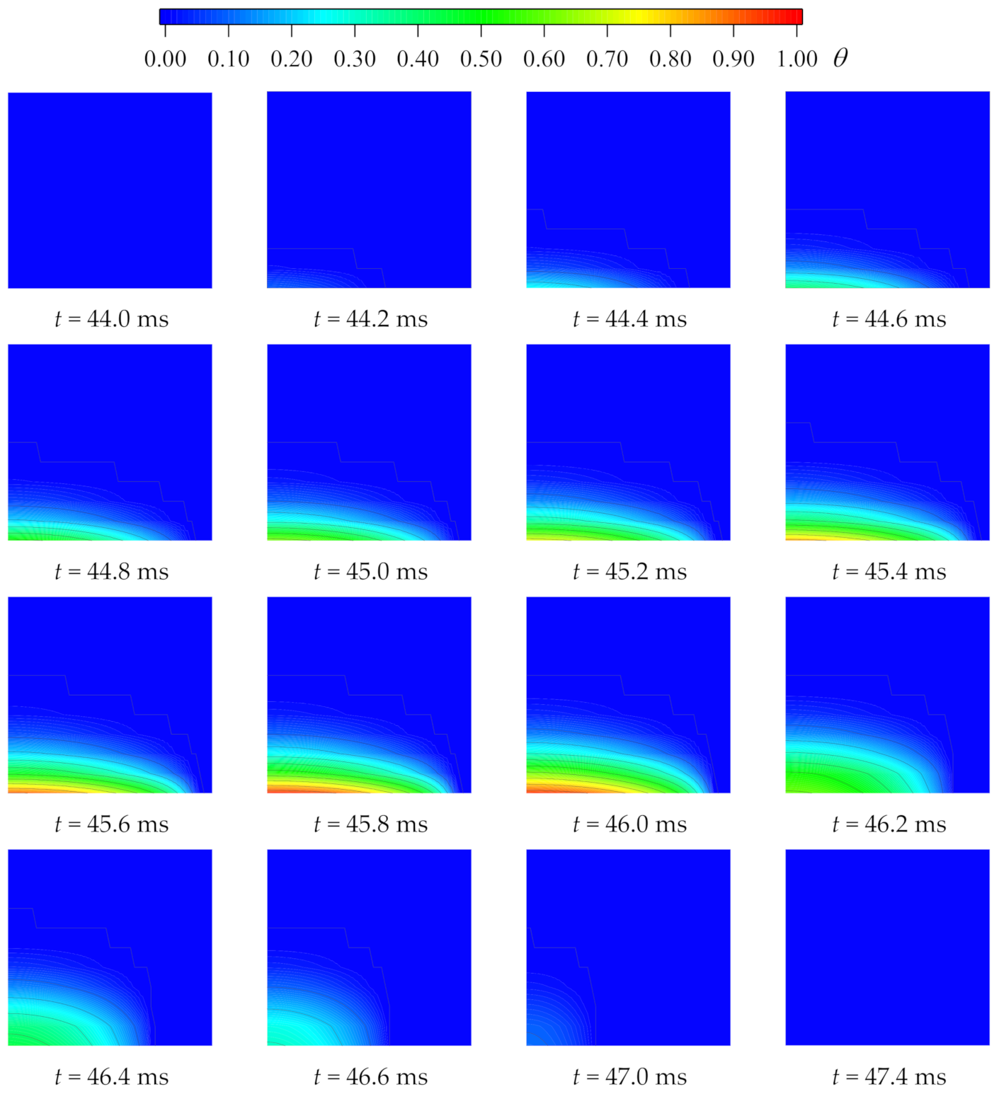
- The PCM thickness has a significant influence on the cooling performance. Results show that the maximum temperature can be maintained around the phase change temperature only if the melted PCM during the heating period can be completely solidified within heat pulse intervals, suggesting that a thickness smaller than 0.1 mm is appropriate.
- (4)
- The heat pluses’ peak heat flux and duty cycle also have effects on the buffer performance of PCM. Results show that low peak heat flux and large duty cycle pulse heating can take full advantage of metallic PCMs.
- (5)
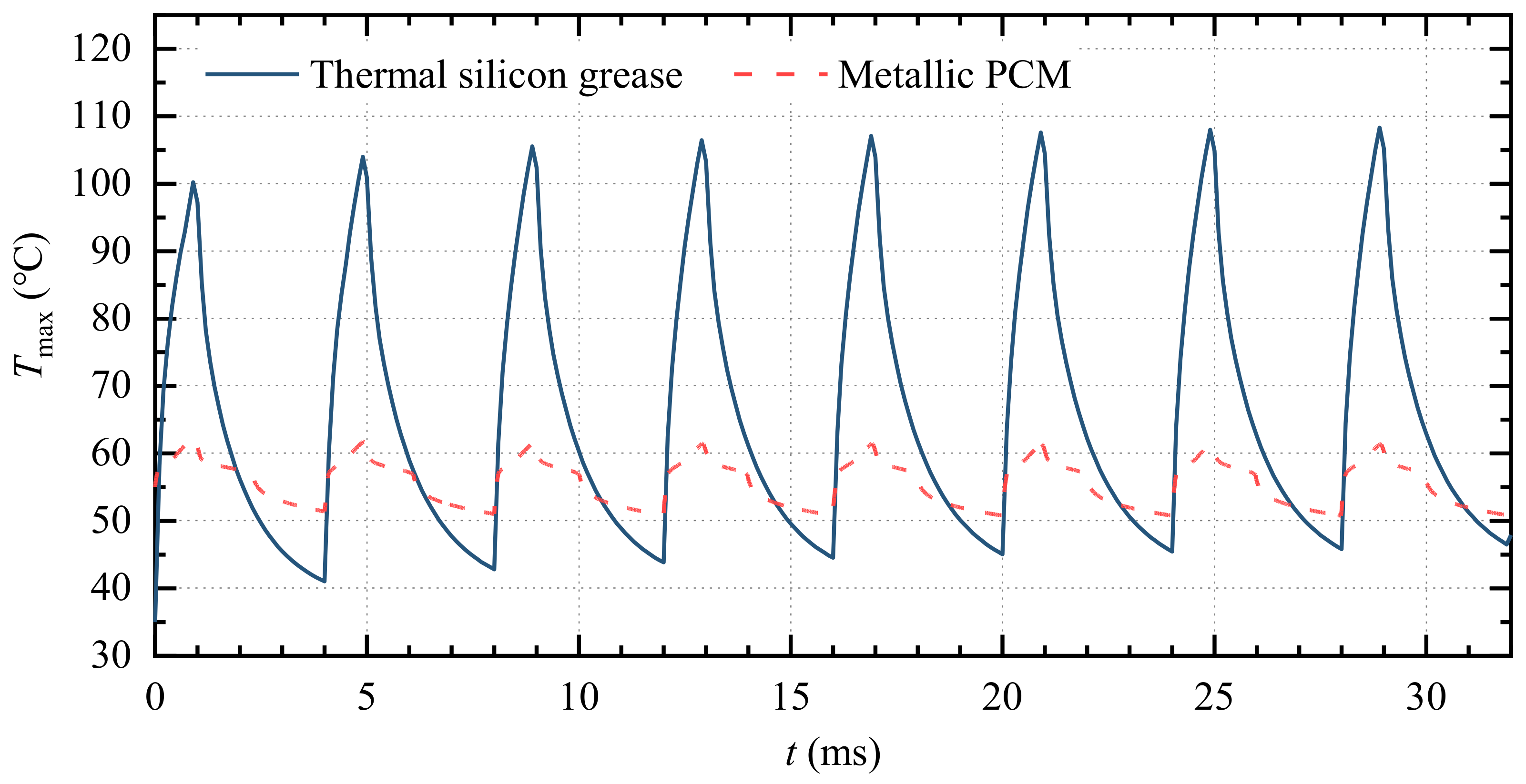
- Compared to the thermal silicon grease, metallic PCM can achieve a lower temperature and a smaller amplitude of fluctuations under pulses, showing a better thermal contact performance.
Author Contributions
Funding
Institutional Review Board Statement
Informed Consent Statement
Data Availability Statement
Conflicts of Interest
Nomenclature
| Cp | specific heat capacity (J·kg−1·K−1) |
| d | jet diameter (mm) |
| H | jet height (mm) |
| h | heat transfer coefficient (W·m−2·K−1) |
| k | thermal conductivity (W·m−1·K−1) |
| L | latent heat (J/kg) |
| Nu | Nusselt number |
| Nu0 | stagnation point Nusselt number |
| ΔP | pressure drop (Pa) |
| QV | volumetric flow rate (L/min) |
| q″ | heat flux (W/cm2) |
| Re | Reynold number |
| T | temperature (°C) |
| Tm | mean temperature of the phase change (°C) |
| t | time (ms) |
| u | velocity (m/s) |
| Greek symbols | |
| δ | the thickness of metallic PCM (mm) |
| ρ | density (kg/m3) |
| γ | average phase change percentage (%) |
| θ | liquid fraction |
| Superscripts | |
| ave | average |
| max | maximum |
References
- Garimella, S.V.; Fleischer, A.S.; Murthy, J.Y.; Keshavarzi, A.; Prasher, R.; Patel, C.; Bhavnani, S.H.; Venkatasubramanian, R.; Mahajan, R.; Joshi, Y.; et al. Thermal Challenges in Next-Generation Electronic Systems. IEEE Trans. Components Packag. Technol. 2008, 31, 801–815. [Google Scholar] [CrossRef]
- Huang, Y.-C.; Hsu, H.-C. Selective Laser Melting Heat Sinks under Jet Impingement Cooling for Heat Dissipation of Higher Light Output LED Lighting in a Limited Space. Appl. Sci. 2020, 10, 3898. [Google Scholar] [CrossRef]
- Zhu, L.Y.; Cao, J.G.; Dong, L.N. Review on Jet Impingement Technology for Spacecraft High-Heat-Flux Removal. Aerosp. Shanghai 2016, 33, 106–112. [Google Scholar] [CrossRef]
- Garimella, S.V.; Nenaydykh, B. Nozzle-geometry effects in liquid jet impingement heat transfer. Int. J. Heat Mass Transf. 1996, 39, 2915–2923. [Google Scholar] [CrossRef]
- Robinson, A.; Schnitzler, E. An experimental investigation of free and submerged miniature liquid jet array impingement heat transfer. Exp. Therm. Fluid Sci. 2007, 32, 1–13. [Google Scholar] [CrossRef]
- Garimella, S.V.; Rice, R.A. Confined and Submerged Liquid Jet Impingement Heat Transfer. J. Heat Transf. 1995, 117, 871–877. [Google Scholar] [CrossRef]
- Womac, D.J.; Incropera, F.P.; Ramadhyani, S. Correlating equations for impingement cooling of small heat sources with multiple circular liquid jets. ASME J. Heat Transf. 1994, 116, 482–486. [Google Scholar] [CrossRef]
- Garimella, S.V. Heat transfer and flow fields in confined jet impingement. Annu. Rev. Heat Transf. 2000, 11, 413–494. [Google Scholar] [CrossRef]
- Nguyen, C.T.; Galanis, N.; Polidori, G.; Fohanno, S.; Popa, C.V.; Le Bechec, A. An experimental study of a confined and submerged impinging jet heat transfer using Al2O3-water nanofluid. Int. J. Therm. Sci. 2009, 48, 401–411. [Google Scholar] [CrossRef]
- Zhang, D.; Qu, H.; Lan, J.; Chen, J.; Xie, Y. Flow and heat transfer characteristics of single jet impinging on protrusioned surface. Int. J. Heat Mass Transf. 2013, 58, 18–28. [Google Scholar] [CrossRef]
- Sathik, M.; Jet, T.K.; Gajanayake, C.J.; Simanjorang, R.; Gupta, A.K. Comparison of power cycling and thermal cycling effects on the thermal impedance degradation in IGBT modules. In Proceedings of the 41st Annual Conference of the IEEE Industrial Electronics Society, Yokohama, Japan, 9–12 November 2015. [Google Scholar] [CrossRef]
- Liu, Z.; Qin, S.; Chen, X.; Chen, D.; Wang, F. PDMS-PDMS Micro Channels Filled with Phase-Change Material for Chip Cooling. Micromachines 2018, 9, 165. [Google Scholar] [CrossRef] [Green Version]
- Iradukunda, A.-C.; Vargas, A.; Huitink, D.; Lohan, D. Transient thermal performance using phase change material integrated topology optimized heat sinks. Appl. Therm. Eng. 2020, 179, 115723. [Google Scholar] [CrossRef]
- Pal, D.; Joshi, Y.K. Application of Phase Change Materials to Thermal Control of Electronic Modules: A Computational Study. J. Electron. Packag. 1997, 119, 40–50. [Google Scholar] [CrossRef]
- Liu, J.; Deng, Z.-S.; He, Z.-Z. Art and Science Towards Noiseless Driving of Liquid Metal for Advanced Thermal Management of High Heat Flux Device. In International Electronic Packaging Technical Conference and Exhibition; American Society of Mechanical Engineers: San Francisco, CA, USA, 2015. [Google Scholar] [CrossRef]
- Xiaohu, Y.; Liu, J. Advanced liquid metal cooling: Historical developments and research frontiers. Sci. Technol. Rev. 2018, 36, 54–66. [Google Scholar]
- Boteler, L.; Fish, M.; Berman, M.; Wang, J. Understanding Trade-Offs of Phase Change Materials for Transient Thermal Mitigation. In Proceedings of the 2019 18th IEEE Intersociety Conference on Thermal and Thermomechanical Phenomena in Electronic Systems (ITherm), Las Vegas, NV, USA, 28–31 May 2019; pp. 870–877. [Google Scholar]
- Cai, Y.; Hong, B.-H.; Wu, W.-X.; Wang, W.-W.; Zhao, F.-Y. Active cooling performance of a PCM-based thermoelectric device: Dynamic characteristics and parametric investigations. Energy 2022, 254, 124356. [Google Scholar] [CrossRef]
- Yoo, D.-W.; Joshi, Y. Energy Efficient Thermal Management of Electronic Components Using Solid–Liquid Phase Change Materials. IEEE Trans. Device Mater. Reliab. 2004, 4, 641–649. [Google Scholar] [CrossRef]
- Hao, G.; Zhou, L.; Ren, H.; Ran, L.; Xie, B. Study on thermal buffering effect of phase change material on press-pack IGBT. Int. J. Heat Mass Transf. 2020, 154, 119584. [Google Scholar] [CrossRef]
- Yang, X.-H.; Tan, S.-C.; Ding, Y.-J.; Wang, L.; Liu, J.; Zhou, Y.-X. Experimental and numerical investigation of low melting point metal based PCM heat sink with internal fins. Int. Commun. Heat Mass Transf. 2017, 87, 118–124. [Google Scholar] [CrossRef]
- Yang, X.-H.; Tan, S.-C.; He, Z.-Z.; Zhou, Y.-X.; Liu, J. Evaluation and optimization of low melting point metal PCM heat sink against ultra-high thermal shock. Appl. Therm. Eng. 2017, 119, 34–41. [Google Scholar] [CrossRef]
- Yang, X.-H.; Tan, S.-C.; He, Z.-Z.; Liu, J. Finned heat pipe assisted low melting point metal PCM heat sink against extremely high power thermal shock. Energy Convers. Manag. 2018, 160, 467–476. [Google Scholar] [CrossRef]
- Shamberger, P.J.; Bruno, N.M. Review of metallic phase change materials for high heat flux transient thermal management applications. Appl. Energy 2020, 258, 113955. [Google Scholar] [CrossRef]
- Muratore, C.; Aouadi, S.; Voevodin, A. Embedded phase change material microinclusions for thermal control of surfaces. Surf. Coatings Technol. 2012, 206, 4828–4832. [Google Scholar] [CrossRef]
- Ollier, E.; Soupremanien, U.; Remondière, V.; Dijon, J.; Le Poche, H.; Seiler, A.; Lefevre, F.; Lips, S.; Kinkelin, C.; Rolland, N.; et al. Thermal management of electronic devices by composite materials integrated in silicon. Microelectron. Eng. 2014, 127, 28–33. [Google Scholar] [CrossRef]
- Sponagle, B.; Groulx, D.; White, M. Experimental Evaluation of a Latent Heat Storage Module with a Heat Spreader for Thermal Management of a Tablet Computer. Appl. Sci. 2021, 11, 3983. [Google Scholar] [CrossRef]
- Maranda, S.; Sponagle, B.; Worlitschek, J.; Groulx, D. Experimental Investigation of Thin PCM Packages and Thermal Spreader for Thermal Management of Portable Electronic Devices. Appl. Sci. 2019, 9, 4613. [Google Scholar] [CrossRef] [Green Version]
- Potthast, F.; Laschefski, H.; Mitra, N.K.; Biswas, G. Numerical investigation of flow structure and mixed convection heat transfer of impinging radial and axial jets. Numer. Heat Transf. Part A Appl. 1994, 26, 123–140. [Google Scholar] [CrossRef]
- Revill, B.K. Chapter 9—Jet mixing. In Mixing in the Process Industries; Harnby, N., Edwards, M.F., Nienow, A.W., Eds.; Butterworth-Heinemann: Oxford, UK, 1992; pp. 159–183. [Google Scholar]
- Tao, W. Numerical Heat Transfer, 2nd ed.; Xi’an Jiaotong University Press: Xi’an, China, 2001. [Google Scholar]
- Muhammad, A.; Selvakumar, D.; Wu, J. Numerical investigation of laminar flow and heat transfer in a liquid metal cooled mini-channel heat sink. Int. J. Heat Mass Transf. 2020, 150, 119265. [Google Scholar] [CrossRef]
- Wilcox, D.C. Turbulence Modeling for CFD; DCW Industries, Inc.: La Canada, CA, USA, 1998. [Google Scholar]
- Khattari, Y.; El Rhafiki, T.; Choab, N.; Kousksou, T.; Alaphilippe, M.; Zeraouli, Y. Apparent heat capacity method to investigate heat transfer in a composite phase change material. J. Energy Storage 2020, 28, 101239. [Google Scholar] [CrossRef]
- El Ouali, A.; Khattari, Y.; Lamrani, B.; El Rhafiki, T.; Zeraouli, Y.; Kousksou, T. Apparent heat capacity method to describe the thermal performances of a latent thermal storage system during discharge period. J. Energy Storage 2022, 52, 104960. [Google Scholar] [CrossRef]
- COMSOL AB. Heat Transfer Module User’s Guide. In COMSOL Multiphysics® v. 5.5; COMSOL AB: Stockholm, Sweden, 2019; pp. 77–80. [Google Scholar]
- Desai, A.; Singh, V.K.; Bhavsar, R.R. Numerical investigation of pcm based thermal control module for space applications. In Proceedings of the 24th National and 2nd International ISHMT-ASTFE Heat and Mass Transfer Conference (IHMTC-2017), Hyderabad, India, 27–30 December 2017. [Google Scholar]
- Manikandan, S.; Selvam, C.; Poddar, N.; Pranjyal, K.; Lamba, R.; Kaushik, S. Thermal management of low concentrated photovoltaic module with phase change material. J. Clean. Prod. 2019, 219, 359–367. [Google Scholar] [CrossRef]
- Mazloum, S.; Awad, S.; Allam, N.; Aboumsallem, Y.; Loubar, K.; Tazerout, M. Modelling plastic heating and melting in a semi-batch pyrolysis reactor. Appl. Energy 2021, 283, 116375. [Google Scholar] [CrossRef]
- Pan, A.-G.; Wang, J.-B.; Zhang, X.-J.; Cao, X.-B. Experimental Research of Electronic Devices Thermal Control Using Metallic Phase Change Materials. J. Harbin Inst. Technol. 2014, 21, 113–121. [Google Scholar]
- Li, C.-Y.; Garimella, S.V. Prandtl-number effects and generalized correlations for confined and submerged jet impingement. Int. J. Heat Mass Transf. 2001, 44, 3471–3480. [Google Scholar] [CrossRef] [Green Version]
- Shishkin, R.A. Investigation of the influence of submicron spherical diamond particles and silicon whiskers on the thermal conductivity of thermal greases. In AIP Conference Proceedings; AIP Publishing: Melville, NY, USA, 2022; Volume 2632, p. 020022. [Google Scholar] [CrossRef]
- Hansson, J.; Nilsson, T.M.J.; Ye, L.; Liu, J. Novel nanostructured thermal interface materials: A review. Int. Mater. Rev. 2018, 63, 22–45. [Google Scholar] [CrossRef]
- Wang, X.; Lu, C.; Rao, W. Liquid metal-based thermal interface materials with a high thermal conductivity for electronic cooling and bioheat-transfer applications. Appl. Therm. Eng. 2021, 192, 116937. [Google Scholar] [CrossRef]
- Hamed, A.; Ndao, S. Modeling of writable thin film liquid metal phase change material for electronics cooling. In Proceedings of the 2017 16th IEEE Intersociety Conference on Thermal and Thermomechanical Phenomena in Electronic Systems (ITherm), Orlando, FL, USA, 30 May–2 June 2017; pp. 1062–1068. [Google Scholar]


| Thermophysical Properties | Solid | Liquid |
|---|---|---|
| ρ (kg/m3) | 9060 | 8200 |
| Cp (J∙kg−1∙K−1) | 323 | 721 |
| k (W∙m−1∙K−1) | 33.2 | 10.6 |
| ΔT⁄2 (K) | 1.5 | |
| L (J/kg) | 28,980 | |
| Mesh | Number of Cells | Tmax /°C | ΔP /Pa | ||
|---|---|---|---|---|---|
| Mesh1 | 26,718 | 63.83 | 6.75 × 10⁻³ | 196.11 | 3.68 × 10⁻¹ |
| Mesh2 | 68,546 | 63.39 | 1.27 × 10⁻² | 268.35 | 1.70 × 10⁻¹ |
| Mesh3 | 127,091 | 62.59 | 5.67 × 10⁻³ | 222.79 | 2.75 × 10⁻² |
| Mesh4 | 323,075 | 62.24 | 6.11 × 10⁻⁴ | 228.93 | 2.81 × 10⁻⁴ |
| Mesh5 | 998,199 | 62.20 | — | 229.00 | — |
| Author | Metallic PCM | Co-Design of PCM and Heat Sink | Numerical Model |
|---|---|---|---|
| DW Yoo et al. [19] | 50Bi/27Pb/13Sn/10Cd | Fill the fan cooled external plate fin heat sink with PCM | PCM melting under forced convection was modeled using the enthalpy–porosity approach, and the heat transfer coefficient on the air-cooled channel surfaces was calculated by correlation. |
| Gaofeng Hao et al. [20] | Vrycul TP-III | Integrate PCM into IGBT molybdenum plate | Only the heat transfer and PCM melting processes were involved, and the apparent heat capacity method was used to model phase transition processes. |
| Ahmed et al. [45] | 50Bi/27Pb/13Sn/10Cd | Thin film metallic PCM in direct contact with the chip | One dimensional model and the enthalpy method were used to model phase transition processes. |
| Xiaohu Yang et al. [21] | 31.6Bi/48.8In/19.6Sn | Fill the internal finned heat sink with PCM | PCM melting processes were modeled using the enthalpy–porosity method, and the natural convection heat transfer coefficient of the heat sink outer wall was set to constant. |
| Xiaohu Yang et al. [22] | 49Bi/21In/18Pb/12Sn | Fill the internal finned heat sink with PCM | Only the heat transfer and PCM melting processes were involved, and the enthalpy–porosity method was used to model phase transition processes. |
| Present work | 49Bi/21In/18Pb/12Sn | Embed PCM into the interface between the chips and the jet impingement heat sink | The k-ω turbulence model and the apparent heat capacity method were used to model the conjugated heat transfer of confined jet impingement cooling and PCM melting. |
Disclaimer/Publisher’s Note: The statements, opinions and data contained in all publications are solely those of the individual author(s) and contributor(s) and not of MDPI and/or the editor(s). MDPI and/or the editor(s) disclaim responsibility for any injury to people or property resulting from any ideas, methods, instructions or products referred to in the content. |
© 2023 by the authors. Licensee MDPI, Basel, Switzerland. This article is an open access article distributed under the terms and conditions of the Creative Commons Attribution (CC BY) license (https://creativecommons.org/licenses/by/4.0/).
Share and Cite
Chen, L.; Wang, Q.; Si, Y.; Hou, Y. Transient Cooling of Millisecond-Pulsed Heat Sources by a Jet Impingement Heat Sink with Metallic Phase Change Material. Appl. Sci. 2023, 13, 1812. https://doi.org/10.3390/app13031812
Chen L, Wang Q, Si Y, Hou Y. Transient Cooling of Millisecond-Pulsed Heat Sources by a Jet Impingement Heat Sink with Metallic Phase Change Material. Applied Sciences. 2023; 13(3):1812. https://doi.org/10.3390/app13031812
Chicago/Turabian StyleChen, Liang, Qi Wang, Yansong Si, and Yu Hou. 2023. "Transient Cooling of Millisecond-Pulsed Heat Sources by a Jet Impingement Heat Sink with Metallic Phase Change Material" Applied Sciences 13, no. 3: 1812. https://doi.org/10.3390/app13031812