Abstract
Microfocusing X-rays direct high-density photons on crystal samples and can enhance the diffraction limit and quality of collected data. However, these intense X-rays can cause radiation damage to the sample, which often results in undesirable structural information. Accordingly, a data collection strategy that minimizes radiation damage is critical to obtaining accurate structural information. In this study, radiation damage in single-point data collection was investigated at two different X-ray exposure times (1 s and 100 ms) using microfocusing X-rays and a thaumatin crystal larger than the beam. The data collection statistics showed that the diffraction intensity of the Bragg peak did not gradually decrease until the crystal rotation reached 180°, and it significantly decreased after exceeding this value. Thaumatin structures exposed to X-rays for 1 s (Thaumatin1s) and 100 ms (Thaumatin100ms) were determined at 1.13 Å resolution. The temperature factors for Asp60, Arg119, Lys163, and Lys187 of thaumatin were increased by radiation damage. Specific radiation damage was observed at the disulfide bond in Thaumatin1s but was negligible in Thaumatin100ms. Splitting and reprocessing Thaumatin100ms showed that electron density maps with minimal radiation damage can be obtained when using minimal data that satisfy the completeness, I/sigma, and CC1/2 parameters. These results expand our understanding of radiation damage phenomena in macromolecules and can be used for data collection applications.
1. Introduction
Macromolecular crystallography (MX) enables the determination of macromolecule crystal structures at atomic resolutions [1]. Such structural information provides useful information for understanding the molecular mechanisms of macromolecules [2,3,4] and provides insights into new drug design [5,6] and rational protein engineering for industrial and medical applications [7,8]. However, despite these advantages, radiation damage due to the absorption of X-ray radiation by crystals remains a major obstacle for MX [9]. When macromolecule crystals are absorbed the X-rays, free radicals are generated in the crystal [10,11] that propagate global or specific radiation damage [12]. In global radiation damage, an overall increase in nonisomorphism in the crystal weakens the diffraction intensity of the crystal, lowers the resolution, increases the volume of the unit cell, and increases the Wilson B coefficient [11,13]. Specific radiation damage affects the electron density map, such as elongation and breakage of disulfide bond sites, decarboxylation of aspartic acid and glutamic acid side chains, disorganization of methionine sulfur, and photoreduction of metal centers [11,13,14,15,16,17,18]. Accordingly, radiation damage reduces the diffraction data quality, disrupts experimental phasing, generates inaccuracy of the solved structure, and results in unreliable biological structures [19,20,21].
The focal size achievable in low-emittance third-generation synchrotron sources is reducing [22]. In particular, it is now possible to focus X-rays to a size of several μm using optical devices such as KB mirrors [23], providing a very high flux density to the sample. These intense X-rays provide a strong signal to collect improved diffraction, absorption, and scattering data. However, when these intense X-rays is continuously exposed to the sample, radiation damage can be caused. To reduce the radiation damage on crystal sample, various attempts have been made to understand radiation damage theoretically and experimentally in MX [9,10,14,24,25,26,27,28,29].
Thaumatin is a plant sweet protein that contains eight disulfide bonds [30]. This protein is often used as a model crystal sample for radiation damage in MX experiments [22,31,32]. For example, Schulze-Briese et al. investigated beam-size effects in radiation damage to thaumatin crystals [22]. X-rays (photons/s = 0.75 × 10¹²) of 82 × 10 μm (h x v) and 85 × 170 μm size were exposed to thaumatin I (300 × 150 × 100 μm3) and thaumatin II (350 × 150 × 150 μm3), respectively, to investigate the radiation damage for each beam size; a negative electron density of disulfide bond Cys159–Cys164 was observed. However, analysis of radiation damage to all disulfide bond sites in thaumatin has not been reported. In addition, because the specific and global radiation damage of crystals differ depending on the X-ray characteristics and collection strategy used, the results of previous studies cannot be applied to all experiments. Accordingly, Bragg peaks and structure analyses according to radiation damage in various data collection scenarios are important for optimal data collection utilization. Among them, research on data quality or radiation damage by using large crystals and a microfocusing beamline of <10 μm is not well known. Theoretically, for single-point data collection, a part of the sample is continuously exposed to X-rays; therefore, multipoint or helical data collection strategies are useful for minimizing X-ray exposure of the same crystal volume [33]. However, it is not applicable on beamlines, unless multipoint or helical data collection is supported. In addition, there may be cases where single-point data collection is inevitably performed depending on the shape of the crystal or the shape of the mounted crystal. Hence, radiation damage studies in single-point data collection considering multiple scenarios will provide useful information on efficient data collection strategies.
To understand the radiation damage caused by MX experiments, radiation damage to crystals during single-point data collection where the crystals were larger than the beam size of microfocusing X-rays was investigated. The statistics of the collected data and quality of each image were comparatively analyzed. Based on the crystal structure, changes in the temperature factors and specific radiation damage to the disulfide bonds of thaumatin were investigated. In addition, strategies for using data with minimal radiation damage were discussed. The results of this study broaden our knowledge of radiation damage and provide opportunities for improving data processing.
2. Materials and Methods
2.1. Crystallization
Thaumatin from Thaumatococcus daniellii (T7638) was purchased from Sigma-Aldrich (Louis, MO, USA). The protein powder was dissolved into a buffer containing 10 mM Tris-HCl and pH 8.0. Thaumatin crystallization was performed using the hanging drop vapor diffusion method at 20 °C. Thaumatin solution (50 mg/mL, 2 μL) and crystallization solution (2 μL) containing 3.5 M tartaric acid were mixed and equilibrate with reservoir solution (500 μL). The bipyramid-shaped thaumatin crystals were grown within 1 day. The dimensions of the thaumatin crystals were approximately 300 × 200 × 150 μm3.
2.2. Data Collection
X-ray diffraction data were collected at beamline 11C of Pohang Light Source II (Pohang, Republic of Korea). Thaumatin crystals were cryoprotected with reservoir solution supplemented with 20% (v/v) ethylene glycol for 5 s and then mounted on the liquid nitrogen stream at 100 K. The X-ray wavelength and photon flux were 0.97641 Å and ~5 × 10¹¹ phs/s, respectively. The horizontal and vertical X-ray beam sizes (FWHM: full-width half-maximum) at the focal point were 3.5 and 8.5 μm, respectively. Thaumatin crystals were X-ray-exposed for 1 s or 100 ms. Diffraction data were recorded on Pilatus 6M. The diffraction images were processed using Xia2 [34] and corrected for absorption using spherical harmonics in AIMLESS [35].
2.3. Structure Determination
The phasing problem was solved using the molecular replacement method using MOLREP [36]. The crystal structure of thaumatin (PDB code 5X9M) [37] was used as a search model. Model building and structure refinement were performed using COOT [38] and REFMAC [39], respectively. The final model was refined using phenix.refine in PHENIX (Québec, QC, Canada) [40]. The geometries of model structures were validated using MolProbity [41]. The structure factors and coordinates were deposited in the Protein Data Bank under accession codes 8HVE (Thaumatin1s) and 8HVF (Thaumatin100ms).
2.4. Structure Analysis
The temperature factors were analyzed using CCP4i [42]. The dose was calculated with RADDOSE-3D [43]. The electron density map and model structure were visualized with PyMOL (https://pymol.org/ (accessed on 1 October 2022)). Peak search was performed using ADXV (https://www.scripps.edu/tainer/arvai/adxv.html (accessed on 1 December 2022)).
3. Results
3.1. Data Collection
In MX with single-point collection, after aligning the crystal to the X-rays, the crystal rotates and collects diffraction data for three-dimensional structural information. When the X-rays are larger than the crystal, all crystal volumes accumulate radiation damage over the X-ray exposure time (Figure 1A). When the crystal is larger than the X-ray, the first time that the crystal is exposed to the X-ray, radiation damage occurs in the area corresponding to the X-ray path (Figure 1B). Then, when the crystal is rotated by the goniometer, the center of the crystal aligned with the X-ray beam is continuously exposed to the X-ray, whereas the crystal volume not previously exposed to the X-ray path is newly exposed to the X-ray for first time (Figure 1B).
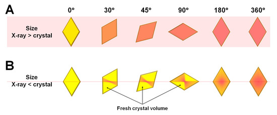
Figure 1.
Schematic view of microfocused X-ray beam path on crystals that are (A) smaller and (B) larger than the X-ray beam.
Accordingly, the X-ray dose is accumulated in the center of the crystal where the X-rays are aligned, and this area contains structural information that corresponds to radiation damage. In contrast, the fresh crystal volume that was not previously exposed to X-rays provides structural information that corresponds to minimal radiation damage. Diffraction data collected when the crystal rotates by 180° include structural information that corresponds to a mixture of radiation damage at the center of the crystal and diffraction information with minimal radiation damage in the fresh crystal volume. In contrast, if the rotation of the crystal sample exceeds 180°, then the crystal is re-exposed at positions where all volumes had been previously exposed (Figure 1B).
To understand the phenomena of radiation damage when a crystal is larger than the X-ray beam, this study exposed a thaumatin crystal (300 × 200 × 150 μm) to a microfocused X-ray beam (3.5 × 8.5 μm, FWHM) and investigated the subsequent radiation damage. One image contains diffraction information for 1°, and the X-ray exposure time was for 1 s (Thaumatin1s) or 100 ms (Thaumatin100ms) per image. For Thaumatin1s, Bragg peaks were clearly observed up to ~1.4 Å in the first image. However, a decrease in the Bragg peak was observed as the X-ray exposure time increased (Figure 2A). When the oscillation reached 360°, Bragg peaks beyond 2.1 Å resolution were not clearly observed (Figure 2A). For Thaumatin100ms, Bragg peaks were observed up to ~1.5 Å in the first diffraction image and continued steadily up to 1.6 Å until the X-ray rotated by 360° (Figure 2B). This indicated that the radiation produced damage that weakened the diffraction intensity of Thaumatin1s but did not have a noticeable effect on Thaumatin100ms.
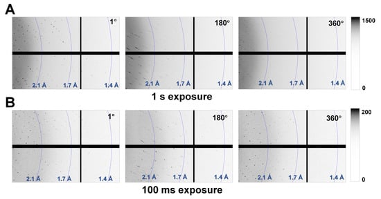
Figure 2.
Magnified views of the diffraction patterns of (A) Thaumatin1s and (B) Thaumatin100ms recorded at oscillation angles of 1°, 180°, and 360°.
Next, to avoid bias in data processing, diffraction data were automatically processed using Xia2, and the standard for resolution cutoff was based on the default value of the program. Thaumatin1s and Thaumatin100ms showed identical tetragonal space groups, and the unit cell dimensions were almost identical, with a difference of less than 0.1%. Although there was a difference in the statistical values of the two data in terms of resolution range, completeness, multiplicity, I/sigma, and CC1/2, whether one set of data was more dominant could not be determined (Table 1).

Table 1.
Data collection and refinement statistics.
Because the data statistics integrated the Bragg peak in all images (Table 1), information on the degree of radiation damage of Thaumatin1s and Thaumatin100ms could not be obtained. Accordingly, to compare the quality of Bragg peaks according to the radiation exposure time, the number of Bragg peaks at I/sigma values of 5, 10, 20, and 30 from each of the collected images were investigated. In normal single-point mode, when exposed to X-rays, the crystal diffraction intensity gradually decreased with increasing exposure time [33]. However, for both Thaumatin1s and Thaumatin100ms, the intensity of Bragg peaks did not decrease in proportion to the exposure time in the range of 1–180° (Figure 3A,B). In Thaumatin1s, the number of Bragg peaks gradually decreased until a rotation of 30°, remained constant until ~120°, and increased again at approximately 160–170° (Figure 3A). Subsequently, the number of peaks decreased rapidly around 180°, remained relatively constant around 220–300°, increased again around 330–340°, and then rapidly decreased around 360° (Figure 3A). Even in the case of Thaumatin100ms, the number of Bragg peaks did not tend to decrease in proportion to the X-ray exposure time in the range of 1–180° (Figure 3B). At around 30° and 160°, the number of Bragg peaks increased from the initial number. In contrast, the number of Bragg peaks detected after 180° was similar to that of the previous 1–180°; however, the relative number of detections decreased (Figure 3B).
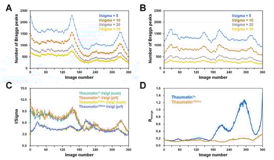
Figure 3.
Analysis of the diffraction images of Thaumatin1s and Thaumatin100ms. Number of Bragg peaks as a function of I/sigma value for (A) Thaumatin1s and (B) Thaumatin100ms. (C) I/sigI with summation and profile fitting for Thaumatin1s and Thaumatin100ms. (D) Rmerge values of Thaumatin1s and Thaumatin100ms.
We speculate that Bragg peaks increase at certain angles (for example, 160° for Thaumatin1s and 30° for Thaumatin100ms) in the data because the corresponding fresh crystal volume exposed to X-rays is larger than that in the other regions. Ultimately, if a crystal is larger than the X-ray beam, then depending on the crystal shape and mounting orientation of the crystal, Bragg peaks at a stronger intensity will be observed at a certain angle regardless of the exposure time.
However, because X-rays penetrate the crystal, after a crystal is rotated 180°, it no longer provides a fresh volume through which X-rays do not penetrate. Therefore, after 180°, X-rays pass at least twice through the whole crystal volume. As a result, Bragg peaks are significantly reduced based on the 180° rotation. In Thaumatin1s, ~1700 Bragg peaks were observed when the I/sigma value was 5 at 60°, but only ~1000 Bragg peaks were observed at 240°. In addition, when I/sigma was 10, 20, and 30, the number of observed Bragg peaks was reduced by ~65% compared with that at the initial 1°. The reduction in these Bragg peaks is considered a factor in the radiation damage caused by exposure of the crystal to X-rays. In Thaumatin100ms, ~1350 Bragg peaks were observed when the I/sigma value was 5 at 90°, while ~1250 Bragg peaks were observed at 270°. In addition, when I/sigma was 10, 20, and 30 at 360°, the number of observed Bragg peaks was reduced by ~20% compared with that at the initial 1°. The reduction in these Bragg peaks is considered a factor in the radiation damage caused by exposure of the crystal to X-rays.
Meanwhile, because X-rays penetrate the crystal, the angle at which the X-ray is exposed to the crystal and its 180° rotation angle have the X-ray path in the same crystal volume. Accordingly, both Thaumatin1s and Thaumatin100ms showed the same tendency for Bragg peaks detected between 1–180° and 181–360°. In the case of Thaumatin1s, the amount of X-ray exposure was higher at 1–180° compared with Thaumatin100ms; hence, it was more affected by radiation damage. As such, the Bragg peak value significantly decreased after 180°. On the other hand, in Thaumatin100ms, the decrease in Bragg peaks after relatively low radiation damage was lower than that of Thaumatin1s.
Meanwhile, Thaumatin1s had a greater number of strong Bragg peaks than Thaumatin100ms, but the overall I/sigma (I) value of Thaumatin1s was lower than that of Thaumatin100ms, because the mean Ibg of Thaumatin1s (Ibg: 182.56) was higher than that of Thaumatin100ms (mean Ibg: 13.45).
Next, I/sigI with summation and profile fitting from integration data for Thaumatin1s and Thaumatin100ms were investigated (Figure 3C). The consumption and profile filtering values from the same data showed very similar trends and I/sigma values. For Thaumatin1s, the I/sigma values for images between 1° and 180° were approximately 6–10. After 180°, the Bragg peak intensity sharply decreased and the I/sigma values for images between 181° and 360° were approximately 4–6, indicating that I/sigma had reduced by approximately 30–40%. For Thaumatin100ms, I/sigI of ~4–6 was observed between 1° and 330° and then decreased to 3 after 330°. I/sigI with summation and profile fitting from integration data were investigated. Meanwhile, Thaumatin100ms showed a lower I/sigI value than Thaumatin1s; however, the background intensity was also low. Therefore, similar statistical results without significant differences were observed in terms of the mean I/sigma.
Next, to investigate the global radiation damage, the Rmerge value of each image was investigated (Figure 3D). The Rmerge value of Thaumatin1s was within 0.2 from 1° to 180°; however, the Rmerge values were 0.6, 1.2, and 1.4 at approximately 200°, 290°, and 360°, respectively. Correspondingly, the intensity of diffraction and the quality of the crystal were reduced in Thaumatin1s. In contrast, the Rmerge value of Thaumatin1s after 180° and at approximately 330° was 0.3, and the corresponding location was a part with a large crystal volume and high intensity. The Rmerge value of Thaumatin100ms was within 0.2 from 1° to 330° but increased to ~0.3 from 330° to 360°. These results indicate that global radiation damage to crystals can be minimized by low X-ray exposure time.
Overall, the diffraction intensity due to radiation damage should decrease because the X-ray exposure time of a crystal increases with a single-point data collection strategy. However, if the crystal is larger than the X-ray, a fresh crystal volume is continuously provided to the X-ray within 1–180° during crystal rotation; thus, a decrease in the intensity that is proportional to time was not observed. In addition, depending on the shape of the crystal and its mounting orientation, more or stronger Bragg peaks may be collected than at the beginning of data collection. Meanwhile, during data collection, the mounting center of the crystal, excluding the fresh crystal volume, is continuously exposed to X-rays, theoretically causing the continuous accumulation of radiation damage.
3.2. Structure Analysis
To better understand the radiation damage, we determined the crystal structures of Thaumatin1s and Thaumatin100ms at 1.13 Å resolution. The Rwork/Rfree of Thaumatin1s and Thaumatin100ms were 18.36/19.24 and 17.06/17.91, respectively (Table 2). This indicates that the model structure of Thaumatin100ms was better fitted into the electron density map than that of Thaumatin1s.
Table 2.
Data refinement statistics.
The thaumatin structure consists of three domains: the flattened β-sandwich domain (Ala1-Thr54, Thr85-Ala127, and Pro178-Ala207), a small disulfide-rich domain (Asp55-Pro84), and a large disulfide-rich domain (Ala128-Cys177) (Figure 4A), which is similar to the findings of a previous report [30]. The superimposition of Thaumatin1s and Thaumatin100ms showed an r.m.s. deviation of 0.033 Å, indicating that the X-ray dose is not critical in changing the main chain conformation of thaumatin.
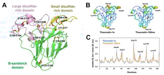
Figure 4.
Crystal structure of thaumatin. (A) Thaumatin consists of β-sandwich (green), small disulfide-rich (yellow), and large disulfide (pink) domains. (B) B-factor putty representation of Thaumatin1s and Thaumatin100ms. (C) Normalized mean B-factors of Thaumatin1s and Thaumatin100ms.
The average temperature factors of Thaumatin1s and Thaumatin100ms were 10.39 and 13.41 Å2, respectively (Table 2). B-factor putty representation showed that several loop regions of Thaumatin1s were relatively more flexible than those of Thaumatin100ms (Figure 4B). A normalized B-factor plot showed that loop regions containing Asp60, Arg119, Lys163, and Lys187 of Thaumatin1s showed high B-factor values when compared with Thaumatin100ms (Figure 4C).
In macromolecular crystallography, the integrity of disulfide bonds and loss of definition of the carboxyl groups of acidic residues are considered a marker for specific radiation damage [12,31]. Thaumatin has eight disulfide bonds in the β-sandwich (Cys9–Cys204 and Cys121–Cys193), small disulfide-rich (Cys56–Cys66 and Cys71–Cys77), and large disulfide-rich (C126–C177, C134–C145, Cys149–Cys158, and Cys159–Cys164) domains. To identify the specific radiation damage, electron density maps of all disulfide bond regions of Thaumatin1s and Thaumatin100ms were investigated. In Thaumatin1s, a negative mFo-DFc electron density map appeared at all positions corresponding to sulfur at all disulfide bond positions (Figure 5A). On the other hand, in C9–C204, C56–C66, and C126–C177, a positive mFo-DFc electron density amp appeared in the opposite direction of the disulfide bond position, whereas in C71, C134, and C158, positive mFo-DFc density maps appeared. Meanwhile, in Thaumatin100ms, no or relatively weak negative mFo–DFc density was observed for all disulfide bond regions except for C134–C145 (Figure 5B), indicating that in one protein, the sensitivity to radiation damage is different depending on the position of the disulfide bond. However, the negative mFo-DFc density map of Thaumatin100ms is negligible for model building. Meanwhile, the C159–C164 disulfide bond of thaumatin showed two conformations in Thaumatin100ms, whereas the electron density map of C159 and C164 in Thaumatin1s was separated (Figure 5A). In summary, the degree of the radiation damage of disulfide bond sites was distinguished according to the X-ray exposure time for both Thaumatin1s and Thaumatin100ms.
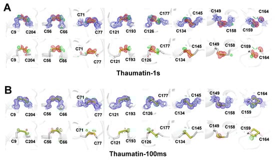
Figure 5.
2mFo-DFc (blue mesh, 1σ) and mFo-DFc (green mesh, 3σ; red mesh, −3σ) electron density map of disulfide bonds in (A) Thaumatin1s and (B) Thaumatin100ms. (Upper) 2mFo-DFc and mFo-DFc; (lower) mFo-DFc.
3.3. Data Dissection
Large crystals provide diffraction data without intensity problems up to a certain rotation angle; however, theoretically, radiation damage always occurs at the center of the crystal where the X-ray was aligned. Accordingly, it is important to collect data that can minimize radiation damage to generate a better model structure. Thaumatin100ms data were split into 90° increments and reprocessed, and structure refinement was performed (Table 3).
Table 3.
Data and refinement statistics of reprocessed Thaumatin100ms.
The images of Thaumatin100ms at 1–90° (Data I), 91–180° (Data II), 181–270° (Data III), and 271–360° (Data IV) were processed up to 1.15, 1.18, 1.17, and 1.26 Å, respectively (Table 3). The results indicated that Data IV had a relatively reduced diffraction limit compared with the other data. The Wilson B factors of Data I, Data II, Data III, and Data VI were 10.60, 10.42, 11.92, and 12.00 Å2, respectively, indicating that Data I and II were relatively lower than Data III and Data IV, which were collected later. There were no significant differences in terms of completeness or CC1/2. Meanwhile, among the four datasets, radiation damage was theoretically minimized in Data I, and this was compared with the Thaumatin100ms (1–360°) data collection statistics. Thaumatin100ms (1–360°) was higher than Data I in terms of resolution and I/sigma; however, the Wilson B-factor indicated that Data I represented an improvement over the total image. Next, refinement was performed using the Thaumatin100ms model for each dataset at 1.3 Å resolution to allow for quantitative comparisons. The Rwork/Rfree of Data I, Data II, Data III, and Data IV were 15.67/17.33, 15.70/16.56, 16.03/17.12, and 16.23/16.83, respectively. The average protein B-factors of Data I, Data II, Data III, and Data IV were 11.85, 12.89, 13.27, and 13.92, respectively. In terms of B-factor, Data I at the beginning was excellent; however, it was difficult to make judgments in terms of Rfree. Accordingly, focusing on the specific radiation damage, the electron density maps of the disulfide bond regions of the four datasets were analyzed (Figure 6).
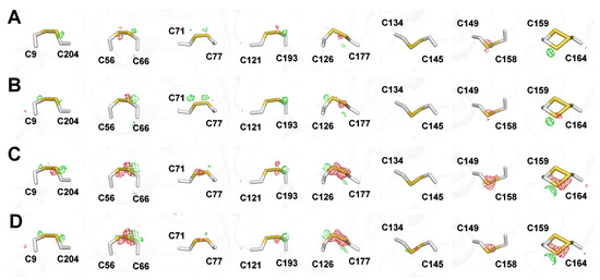
Figure 6.
mFo–DFc (green mesh, 3σ; red mesh, −3σ) electron density map of disulfide bonds in Thaumatin100ms for (A) Data I (1–90°), (B) Data II (91–180°), (C) Data III (181–270°), and (D) Data IV (271–360°).
In the mFo-DFc electron density analysis, Data I and Data II did not show any notable negative electron density maps while Data III and Data IV showed strong negative density maps around disulfide bonds C56–C66, C126–C177, C149–C158, and C159–C164. As a result, no notable radiation damage was observed in the overall data statistics and electron density map for Thaumatin100ms (1–360°). However, based on the electron density map, specific radiation damage occurred for some disulfide bonds as the X-ray exposure time increased, even for Thaumatin100ms. This indicates that structural information with minimized radiation damage can be obtained by minimizing diffraction images.
4. Discussion
In MX, various data collection strategies, such as single-point, multipoint, and helical data collection, have been reported [33]. Theoretically, to minimize radiation damage, multipoint data collection or helical data collection with minimal X-ray exposure to the same crystal volume is preferred. However, these functions may not be supported by the beamline, or single-point data collection must be performed depending on the characteristics or shape of the crystal. In such cases, it is important to conduct various experimental investigations on how to minimize radiation damage in single-point data collection.
Here, we investigated radiation damage during single-point data collection when the protein crystal sample used was larger than the microfocusing beam. Generally, the radiation damage on the crystal increases as the exposure time increases, and the crystal diffraction intensity gradually decreases [33]. However, our experimental results show that if the crystal sample is larger than the X-ray, then the diffraction intensity may not necessarily show a tendency to decrease because the fresh crystal volume is continuously exposed to X-rays while the crystal is rotating during data collection. In addition, the diffraction intensity can increase more than before in the case of a region that is enlarged in a fresh crystal volume (e.g., 160° in Thaumatin1s or 30° in Thaumatin100ms) exposed to X-rays. On the other hand, when using a microfocusing beam, the fresh crystal volume exposed to X-rays is greater when a larger crystal is used. Thus, the volume ratio of the radiation-damaged crystal to the total diffraction information may be reduced. Therefore, large crystals must be used to achieve the effect of minimizing radiation damage, even with microfocused beams.
Meanwhile, because X-rays are continuously exposed to the center of the crystal, which is aligned with the X-ray, the diffraction intensity from the crystal center theoretically decreases and radiation damage is accumulated. Accordingly, the radiation-damaged diffraction patterns from the center of the crystal and diffraction patterns from the fresh crystal volume are mixed until the crystal rotation reaches 180°. However, because there is no fresh crystal volume after 180°, significant radiation damage information is included.
In the total data collection statistics of Thaumatin1s and Thaumatin100ms, no numerical difference that can be regarded as radiation damage was found, and clear differences were observed when individual images of each data were analyzed. However, because the crystal is larger than the X-ray beam, characteristics that can be regarded as radiation damage were not found until the crystal was rotated by 180°, and radiation damage could be distinguished after 180° when X-rays were exposed at least twice. For Thaumatin1s, which was exposed to X-rays for a long time, a significant decrease in the intensity and number of Bragg peaks was observed after the crystal was rotated 180° and the Rmerge value increased, thus confirming that global radiation damage occurred. For Thaumatin100ms, there was no noticeable deterioration in data quality as the X-ray exposure time increased in terms of the Bragg peak intensity, I/sigma, or Rmerge.
Accordingly, in terms of data collection, if a large crystal with high symmetry (for example, a tetragonal space group) is exposed to a microfocusing beam, completed data collection before 180° rotation is possible. However, for a large crystal with low symmetry (for example, a triclinic space group), data collection over more than 180° of rotation is required. In this case, to reduce radiation damage, a strategy to minimize the amount of X-rays exposed to the crystal by reducing the X-ray exposure time or using an attenuator is required. Conversely, if the crystal is large and the fresh crystal volume is larger than the area exposed to overlapping X-rays, the diffraction information of the fresh crystal volume will be dominant. Therefore, density information with relatively less radiation damage can be included. Accordingly, the larger the size of the crystal in the single-point data collection, then radiation damage information can be minimized both statistically and theoretically.
Through individual diffraction image analysis, it was confirmed that Thaumatin1s experienced higher radiation damage than Thaumatin100ms, and in the protein crystal structure analysis, differences due to radiation damage were observed in the temperature factor and disulfide bond electron density maps. As a result of B-factor presentation and normalized B-factor analysis, it was confirmed that the temperature factors for Asp60, Arg119, Lys163, and Lys187 of Thaumatin1s were increased, and they were commonly located in the outer loop region of thaumatin. On the other hand, the electron density analysis produced a negative electron density map, which is considered as specific radiation damage, for all disulfide bonds of Thaumatin1s. This indicates that specific radiation damage can be observed at all other disulfide bonds in thaumatin in addition to the previously reported C159–C164 region. In contrast, for Thaumatin100ms, a significant negative mFo-Dfc electron density map, which can be considered as specific radiation damage, was not observed for disulfide bonds.
Nevertheless, in Thaumatin100ms, radiation damage partially occurs because the X-rays are constantly exposed to the center of the crystal aligned with the X-rays. To track radiation damage that could not be distinguished from the entire data, the entire image of Thaumatin100ms was divided into 90° intervals and reprocessed. This result showed that the quality of the statistics deteriorated as X-ray exposure continued in terms of resolution limit or B-factor. In particular, electron density map analysis showed that notable negative mFo-Dfc electron density maps were observed in Data III and Data IV of Thaumatin100ms. The lack of noticeable radiation damage in the entire Thaumatin100ms image is considered to be due to the overall average of Data I, II, III, and IV. Accordingly, Data I of Thaumatin100ms were optimal for minimizing radiation damage. Taken together, it was possible to identify the tendency of radiation damage using data collection or statistical values of structure refinement. In particular, analysis via electron density map was able to more intuitively reveal the radiation damage.
5. Conclusions
In this study, radiation damage that occurred under two exposure times to a crystal larger than the microfocusing X-ray beam was analyzed based on data collection statistics and electron density maps of thaumatin. The results of this study showed that when diffraction data were collected by the application of a microfocusing beam on a large crystal, radiation damage could be significantly increased after exposure to 180° rotation. In addition, crystal structures with minimal radiation damage can be determined by processing the minimum diffraction image that satisfies the data collection statistics.
Funding
This work was funded by the National Research Foundation of Korea (NRF) (NRF-2017M3A9F6029736 and NRF-2021R1I1A1A01050838) and Korea Initiative for Fostering University of Research and Innovation (KIURI) Program of the NRF (NRF-2020M3H1A1075314). This study was supported by ProGen.
Institutional Review Board Statement
Not applicable.
Informed Consent Statement
Not applicable.
Data Availability Statement
Diffraction images have been deposited in Zenodo under the accession https://doi.org/10.5281/zenodo.7403182.
Acknowledgments
I would like to thank the beamline staffs at the 11C beamline at the Pohang Accelerator Laboratory for their assistance with data collection.
Conflicts of Interest
The author declares no conflict of interest.
References
- McPherson, A.; Gavira, J.A. Introduction to protein crystallization. Acta Crystallogr. F Struct. Biol. Commun. 2013, 70, 2–20. [Google Scholar] [CrossRef] [PubMed]
- Nam, K.H.; Haitjema, C.; Liu, X.; Ding, F.; Wang, H.; DeLisa, M.P.; Ke, A. Cas5d protein processes pre-crRNA and assembles into a cascade-like interference complex in subtype I-C/Dvulg CRISPR-Cas system. Structure 2012, 20, 1574–1584. [Google Scholar] [CrossRef] [PubMed]
- Nam, K.H. Crystal structure of human brain-type fatty acid-binding protein FABP7 complexed with palmitic acid. Acta Crystallogr. D Struct. Biol. 2021, 77, 954–965. [Google Scholar] [CrossRef] [PubMed]
- Nam, K.H. Structural analysis of metal chelation of the metalloproteinase thermolysin by 1,10-phenanthroline. J. Inorg. Biochem. 2021, 215, 111319. [Google Scholar] [CrossRef] [PubMed]
- Zheng, H.; Hou, J.; Zimmerman, M.D.; Wlodawer, A.; Minor, W. The future of crystallography in drug discovery. Expert Opin. Drug Discov. 2013, 9, 125–137. [Google Scholar] [CrossRef]
- Hogg, T.; Hilgenfeld, R. Protein Crystallography in Drug Discovery. In Comprehensive Medicinal Chemistry II; Elsevier Science: Amsterdam, The Netherlands, 2007; pp. 875–900. [Google Scholar]
- Roda, S.; Robles-Martín, A.; Xiang, R.; Kazemi, M.; Guallar, V. Structural-Based Modeling in Protein Engineering. A Must Do. J. Phys. Chem. B 2021, 125, 6491–6500. [Google Scholar] [CrossRef]
- Kuhlman, B.; Bradley, P. Advances in protein structure prediction and design. Nat. Rev. Mol. Cell Biol. 2019, 20, 681–697. [Google Scholar] [CrossRef]
- Shelley, K.L.; Garman, E.F. Quantifying and comparing radiation damage in the Protein Data Bank. Nat. Commun. 2022, 13, 1314. [Google Scholar] [CrossRef]
- Taberman, H. Radiation Damage in Macromolecular Crystallography—An Experimentalist’s View. Crystals 2018, 8, 157. [Google Scholar] [CrossRef]
- Murray, J.; Garman, E. Investigation of possible free-radical scavengers and metrics for radiation damage in protein cryocrystallography. J. Synchrotron Radiat. 2002, 9, 347–354. [Google Scholar] [CrossRef]
- Weik, M.; Ravelli, R.B.G.; Kryger, G.; McSweeney, S.; Raves, M.L.; Harel, M.; Gros, P.; Silman, I.; Kroon, J.; Sussman, J.L. Specific chemical and structural damage to proteins produced by synchrotron radiation. Proc. Natl. Acad. Sci. USA 2000, 97, 623–628. [Google Scholar] [CrossRef] [PubMed]
- Ravelli, R.B.G.; McSweeney, S.M. The ‘fingerprint’ that X-rays can leave on structures. Structure 2000, 8, 315–328. [Google Scholar] [CrossRef] [PubMed]
- Carugo, O.; Carugo, K.D. When X-rays modify the protein structure: Radiation damage at work. Trends Biochem. Sci. 2005, 30, 213–219. [Google Scholar] [CrossRef] [PubMed]
- Weiss, M.S.; Panjikar, S.; Mueller-Dieckmann, C.; Tucker, P.A. On the influence of the incident photon energy on the radiation damage in crystalline biological samples. J. Synchrotron Radiat. 2005, 12, 304–309. [Google Scholar] [CrossRef] [PubMed]
- Corbett, M.C.; Latimer, M.J.; Poulos, T.L.; Sevrioukova, I.F.; Hodgson, K.O.; Hedman, B. Photoreduction of the active site of the metalloprotein putidaredoxin by synchrotron radiation. Acta Crystallogr. D Biol. 2007, 63, 951–960. [Google Scholar] [CrossRef]
- Garman, E.F. Radiation damage in macromolecular crystallography: What is it and why should we care? Acta Crystallogr. D Biol. 2010, 66, 339–351. [Google Scholar] [CrossRef]
- Burmeister, W.P. Structural changes in a cryo-cooled protein crystal owing to radiation damage. Acta Crystallogr. D Biol. 2000, 56, 328–341. [Google Scholar] [CrossRef]
- McCoy, A.J.; Read, R.J. Experimental phasing: Best practice and pitfalls. Acta Crystallogr. D Biol. 2010, 66, 458–469. [Google Scholar] [CrossRef]
- Schmidt, M.; Šrajer, V.; Purwar, N.; Tripathi, S. The kinetic dose limit in room-temperature time-resolved macromolecular crystallography. J. Synchrotron Radiat. 2012, 19, 264–273. [Google Scholar] [CrossRef]
- Matsui, Y.; Sakai, K.; Murakami, M.; Shiro, Y.; Adachi, S.-i.; Okumura, H.; Kouyama, T. Specific Damage Induced by X-ray Radiation and Structural Changes in the Primary Photoreaction of Bacteriorhodopsin. J. Mol. Biol. 2002, 324, 469–481. [Google Scholar] [CrossRef]
- Schulze-Briese, C.; Wagner, A.; Tomizaki, T.; Oetiker, M. Beam-size effects in radiation damage in insulin and thaumatin crystals. J. Synchrotron Radiat. 2005, 12, 261–267. [Google Scholar] [CrossRef] [PubMed]
- Kim, J.; Kim, H.Y.; Park, J.; Kim, S.; Kim, S.; Rah, S.; Lim, J.; Nam, K.H. Focusing X-ray free-electron laser pulses using Kirkpatrick-Baez mirrors at the NCI hutch of the PAL-XFEL. J. Synchrotron Radiat. 2018, 25, 289–292. [Google Scholar] [CrossRef] [PubMed]
- de la Mora, E.; Coquelle, N.; Bury, C.S.; Rosenthal, M.; Holton, J.M.; Carmichael, I.; Garman, E.F.; Burghammer, M.; Colletier, J.-P.; Weik, M. Radiation damage and dose limits in serial synchrotron crystallography at cryo- and room temperatures. Proc. Natl. Acad. Sci. USA 2020, 117, 4142–4151. [Google Scholar] [CrossRef] [PubMed]
- Kim, J.; Nam, K.H. X-ray-Induced Heating in the Vicinity of the X-ray Interaction Point. Appl. Sci. 2023, 13, 717. [Google Scholar] [CrossRef]
- Sliz, P.; Harrison, S.C.; Rosenbaum, G. How does Radiation Damage in Protein Crystals Depend on X-Ray Dose? Structure 2003, 11, 13–19. [Google Scholar] [CrossRef] [PubMed]
- Warkentin, M.; Hopkins, J.B.; Badeau, R.; Mulichak, A.M.; Keefe, L.J.; Thorne, R.E. Global radiation damage: Temperature dependence, time dependence and how to outrun it. J. Synchrotron Radiat. 2013, 20, 7–13. [Google Scholar] [CrossRef]
- Watenpaugh, K.D. Macromolecular crystallography at cryogenic temperatures. Curr. Opin. Struc. Biol. 1991, 1, 1012–1015. [Google Scholar] [CrossRef]
- Lee, K.; Lee, D.; Baek, S.; Kim, J.; Park, J.; Lee, S.J.; Park, S.; Kim, J.; Lee, J.-L.; Chung, W.K.; et al. Radiation Damage of Polydimethylsiloxane and Polyimide by X-ray Free-Electron Laser. Appl. Sci. 2022, 12, 8431. [Google Scholar] [CrossRef]
- Ogata, C.M.; Gordon, P.F.; de Vos, A.M.; Kim, S.-H. Crystal structure of a sweet tasting protein thaumatin I, at 1·65 Å resolution. J. Mol. Biol. 1992, 228, 893–908. [Google Scholar] [CrossRef]
- Nass, K.; Gorel, A.; Abdullah, M.M.; Martin, A.V.; Kloos, M.; Marinelli, A.; Aquila, A.; Barends, T.R.M.; Decker, F.-J.; Bruce Doak, R.; et al. Structural dynamics in proteins induced by and probed with X-ray free-electron laser pulses. Nat. Commun. 2020, 11, 1814. [Google Scholar] [CrossRef] [PubMed]
- Russi, S.; González, A.; Kenner, L.R.; Keedy, D.A.; Fraser, J.S.; van den Bedem, H. Conformational variation of proteins at room temperature is not dominated by radiation damage. J. Synchrotron Radiat. 2017, 24, 73–82. [Google Scholar] [CrossRef] [PubMed]
- Yamamoto, M.; Hirata, K.; Yamashita, K.; Hasegawa, K.; Ueno, G.; Ago, H.; Kumasaka, T. Protein microcrystallography using synchrotron radiation. IUCrJ 2017, 4, 529–539. [Google Scholar] [CrossRef] [PubMed]
- Winter, G. xia2: An expert system for macromolecular crystallography data reduction. J. Appl. Crystallogr. 2009, 43, 186–190. [Google Scholar] [CrossRef]
- Evans, P.R.; Murshudov, G.N. How good are my data and what is the resolution? Acta Crystallogr. D Biol. 2013, 69, 1204–1214. [Google Scholar] [CrossRef]
- Vagin, A.; Teplyakov, A. Molecular replacement with MOLREP. Acta Crystallogr. D Biol. Crystallogr. 2010, 66, 22–25. [Google Scholar] [CrossRef] [PubMed]
- Masuda, T.; Okubo, K.; Murata, K.; Mikami, B.; Sugahara, M.; Suzuki, M.; Temussi, P.A.; Tani, F. Subatomic structure of hyper-sweet thaumatin D21N mutant reveals the importance of flexible conformations for enhanced sweetness. Biochimie 2019, 157, 57–63. [Google Scholar] [CrossRef]
- Emsley, P.; Cowtan, K. Coot: Model-building tools for molecular graphics. Acta Crystallogr. D Biol. Crystallogr. 2004, 60, 2126–2132. [Google Scholar] [CrossRef] [PubMed]
- Murshudov, G.N.; Skubak, P.; Lebedev, A.A.; Pannu, N.S.; Steiner, R.A.; Nicholls, R.A.; Winn, M.D.; Long, F.; Vagin, A.A. REFMAC5 for the refinement of macromolecular crystal structures. Acta Crystallogr. D Biol. Crystallogr. 2011, 67, 355–367. [Google Scholar] [CrossRef]
- Liebschner, D.; Afonine, P.V.; Baker, M.L.; Bunkoczi, G.; Chen, V.B.; Croll, T.I.; Hintze, B.; Hung, L.W.; Jain, S.; McCoy, A.J.; et al. Macromolecular structure determination using X-rays, neutrons and electrons: Recent developments in Phenix. Acta Crystallogr. D Struct. Biol. 2019, 75, 861–877. [Google Scholar] [CrossRef]
- Williams, C.J.; Headd, J.J.; Moriarty, N.W.; Prisant, M.G.; Videau, L.L.; Deis, L.N.; Verma, V.; Keedy, D.A.; Hintze, B.J.; Chen, V.B.; et al. MolProbity: More and better reference data for improved all-atom structure validation. Protein Sci. 2018, 27, 293–315. [Google Scholar] [CrossRef]
- Winn, M.D.; Ballard, C.C.; Cowtan, K.D.; Dodson, E.J.; Emsley, P.; Evans, P.R.; Keegan, R.M.; Krissinel, E.B.; Leslie, A.G.; McCoy, A.; et al. Overview of the CCP4 suite and current developments. Acta Crystallogr. D Biol. Crystallogr. 2011, 67, 235–242. [Google Scholar] [CrossRef] [PubMed]
- Zeldin, O.B.; Gerstel, M.; Garman, E.F. RADDOSE-3D: Time- and space-resolved modelling of dose in macromolecular crystallography. J. Appl. Crystallogr. 2013, 46, 1225–1230. [Google Scholar] [CrossRef]


Disclaimer/Publisher’s Note: The statements, opinions and data contained in all publications are solely those of the individual author(s) and contributor(s) and not of MDPI and/or the editor(s). MDPI and/or the editor(s) disclaim responsibility for any injury to people or property resulting from any ideas, methods, instructions or products referred to in the content. |
© 2023 by the author. Licensee MDPI, Basel, Switzerland. This article is an open access article distributed under the terms and conditions of the Creative Commons Attribution (CC BY) license (https://creativecommons.org/licenses/by/4.0/).