Article

Biomechanical Modeling of Human–Robot Accident Scenarios: A Computational Assessment for Heavy-Payload-Capacity Robots

1
Department of Mechanical Engineering, Capital University of Science and Technology, Islamabad 45750, Pakistan
2
Department of Biosciences, School of Science & Technology, Nottingham Trent University, Nottingham NG11 8NS, UK
3
Digital Innovation Research Group, Department of Engineering, School of Science & Technology, Nottingham Trent University, Nottingham NG11 8NS, UK
4
Institute for Intermodal Transport and Logistic Systems, TU Braunschweig, Hermann-Blenk-Straße 42, 38108 Braunschweig, Germany
*
Author to whom correspondence should be addressed.
Appl. Sci. 2023, 13(3), 1957; https://doi.org/10.3390/app13031957
Submission received: 15 November 2022 / Revised: 14 December 2022 / Accepted: 27 January 2023 / Published: 2 February 2023
(This article belongs to the Topic Human–Machine Interaction)

Abstract

:
Exponentially growing technologies such as intelligent robots in the context of Industry 4.0 are radically changing traditional manufacturing to intelligent manufacturing with increased productivity and flexibility. Workspaces are being transformed into fully shared spaces for performing tasks during human–robot collaboration (HRC), increasing the possibility of accidents as compared to the fully restricted and partially shared workspaces. The next technological epoch of Industry 5.0 has a heavy focus on human well-being, with humans and robots operating in synergy. However, the reluctance to adopt heavy-payload-capacity robots due to safety concerns is a major hurdle. Therefore, the importance of analyzing the level of injury after impact can never be neglected for the safety of workers and for designing a collaborative environment. In this study, quasi-static and dynamic analyses of accidental scenarios during HRC are performed for medium- and low-payload-capacity robots according to the conditions given in ISO TS 15066 to assess the threshold level of injury and pain, and is subsequently extended for high speeds and heavy payloads for collaborative robots. For this purpose, accidental scenarios are simulated in ANSYS using a 3D finite element model of an adult human index finger and hand, composed of cortical bone and soft tissue. Stresses and strains in the bone and tissue, and contact forces and energy transfer during impact are studied, and contact speed limit values are estimated. It is observed that heavy-payload-capacity robots must be restricted to 80% of the speed limit of low-payload-capacity robots. Biomechanical modeling of accident scenarios offers insights and, therefore, gives confidence in the adoption of heavy-payload robots in factories of the future. The analysis allows for prediction and assessment of different hypothetical accidental scenarios in HRC involving high speeds and heavy-payload-capacity robots.

1. Introduction

Industrial robots, from the last fifty years, have been widely used in industrial manufacturing, to the effect of complementing the proficiencies of human workers and relieving them from non-ergonomic, repetitive, uncomfortable, and dangerous tasks. Robot utilization is continuously increasing in industrial environments with a growth rate of about fourteen percent, yearly [1]. Moreover, it is estimated that nearly 2.1 million industrial robots will be deployed around the world in the near future [2]. Conventional industrial robots work with human workers either in a completely separated or in partially shared workspaces. The current exposure of humans with industrial robots is up to a limited extent in the workspace, where the robot is equipped with appropriate safety controls that completely stop the machine in case of any workspace violation. This causes resetting and stoppage actions to be triggered and hinders productive time [3]. With the advent of Industry 4.0, there has been a paradigm shift from automated manufacturing to intelligent manufacturing concepts [4]. In Industry 4.0, industrial robots have shifted from isolation into a collaborative work environment, where humans and robots share workspaces fully without any barriers, termed human–robot collaboration (HRC) [5,6]. A collaborative work environment is a core part of the manufacturing setups involved in Industry 4.0 where both humans and robots are pooling up their specific capabilities. Hand guiding, speed and separation monitoring, and power and force limiting are the level of HRC with partially separated, completely restricted, and fully shared workspaces, respectively. Direct deployment of intelligent robots in fully shared workspaces in HRC increases the possibility of accidents. There is extensive literature on using advances in Artificial Intelligence for safe Human–Robot Interaction to avoid collision, using computer vision [7], an array of sensors and techniques such as Reinforcement Learning [8,9], Digital Twins, and Deep Learning [10]. However, in case of any type of robot failure or cyber-attack intended to cause harm [11], the large amount of impact forces created during accidents can create minor, moderate, and major injury to the human workers. There is also the consideration that converting present industrial robots into interactive ones for safe HRC further increases the risk of accidents [12,13]. Therefore, in the factory of the future, safety will be an intrinsic part of the Collaborative Robotic Cyber Physical Systems. There is a list of reported accidents that includes fatality and non-fatality cases with injury and pain even using the full safety protocols and isolated work environments in developed countries such as China, Japan, the United States, and Germany, where robot use is popular in industry [14]. Environmental conditions, human error, and engineering error could be the reason for the accidents during HRC [15]. Jiang et al. reported thirty-two fatal and non-fatal accidents that occurred due to maintenance error and programming error [16]. Fryman et al. reported thirty-one cases in which workers were injured because of operators’ error and maintenance errors, whereas eight cases were fatal injuries [17]. The Occupational Safety and Health Administration (OSHA) has also reported many fatal as well as non-fatal accidents occurring due to low-, medium-, and heavy-payload-capacity robots working in the non-collaborative environment since 1984. The human body regions that were affected during collisions between humans and robots were the arm, hand, shoulders, chest, neck, head, ribs, fingers, and knuckle [18]. The harm varies from minor injuries to fatal injuries. Therefore, safety issues are of prime importance for safe HRC to minimize the number of accidents. For appropriate safety standards in such systems, new regulations are established for the design and application to allow HRC in industrial environments [19]. Spanish UNE-EN 755, American ANSI/RIA R15.06, ISO 10218, and Technical Specification ISO/TS 15066:2016 are the national and international standards that incorporate robot-associated risks for safe human and robot interaction. In future manufacturing, HRC in the context of smart factories will involve heavy-payload-capacity robots that will increase the chances and magnitude of impacts due to several types of failures [20].
Therefore, for a safe collaborative environment in HRC, it is important to analyze the accidental impact on the human body either by estimating the pain tolerance or by quantifying the level of injury followed by impact. Several methods have been adopted by researchers to measure the tolerable pain level in case of impact in HRC. A pneumatic-cylinder-based actuator was used in one study to deliver impacts on twelve different regions of human volunteers for calculating the tolerable impact forces, but it was suggested to follow a simulations-based approach to include different surfaces of industrial robots [21]. A passive mechanical lower arm, which mimicked human characteristics, was used as an alternative to the human volunteers for evaluating pain level, as presented in [22]. Similarly, the Association for the Advancement of automotive Medicine (AAAM) has divided the human body into different regions for automobile crash-tests for the evaluation of injury level and has proposed standard injury scales such as the Abbreviated Injury Scale (AIS) and Maximum Abbreviated Injury Scale (MAIS) to assess the injury level after impact during HRC [23]
In this work, we assessed the level of injury during human–robot accidental interaction. The Finite Element model of a human hand and a single index finger was selected to simulate the scenarios of human–robot accidents for the purpose of validation, reinforcement, and extension of the Technical Standard TS/15066 standard for Robots and Robotic devices [24]. Different cases of quasi-static and dynamic analysis were performed to estimate the level of damage expected in the case of accidents involving low-, medium-, and heavy-payload-capacity robots. No such analysis has previously been carried out for biomechanical modeling of accident scenarios for different-payload-capacity robots. This work offers insights into the impact of loading conditions and contact velocities on expected injury level, thus boosting confidence in the adoption of heavy-payload-robots in factories of the future.
The paper is organized as follows: In Section 2, we present the details of the finite element model of a human hand and finger, including its geometry, material properties, joints, and meshing. Section 3 describes the conditions of the virtual experiments involving a static analysis and hypothetical high-speed accidental scenarios. Results and Analysis are presented in Section 4. Discussions on some important results as well as the limitations of this study are presented in Section 5, and, finally, Section 6 presents the conclusions and future work.

2. Material and Methods

An adult human hand was selected in this work for quasi-static and dynamic analysis to simulate a human–robot accidental case because of its wide use in daily environments, and there is a list of accidents that involve the human hand in human–robot shared workspaces. A single index finger was also developed to validate the analysis performed in TS/ISO15066 for injury level due to human–robot accidental interaction.

2.1. Design of Finite Element Human Hand Model

The finite element model of the human hand used here consisted of metacarpals, phalanges, joints, and human hand tissue. For unidirectional loading, revolute joints were used to mimic the distal interphalangeal joint (DIP) ranges from −10° to +22°, proximal interphalangeal joint (PIP) ranges from −10° to +90°, and metacarpophalangeal joint (MCP) ranges from −45° to +45°, which fall within the range of motion for an index finger [25]. For cases with mixed loading, the joint was simulated using a spherical joint in ANSYS when DOFs are expected to be significant. The clearance between the bones such as metacarpals and phalanges was introduced to mimic the sliding of bones on cartilage. The 3D model of a human hand and index figure was created using Autodesk ® 3ds Max 2018, edited in Autodesk ® Mesh mixer 2017 and exported in STL file format. Next, the model was imported in ANSYS Discovery SpaceClaim and converted into the required solid bodies for analysis, carried out in ANSYS ® Workbench 2021 R2. Figure 1 shows the FE model of a (a) hand with bones and tissue, and an (b) index finger with degrees of freedom.

2.2. Material of FE Human Hand Model

The material properties of bones, soft tissues, and joints employed for the analysis in this work are presented in Table 1. Several hyperelastic material models are available and have been cited in the literature for the modeling of soft tissue, such as the Neo–Hookean, Mooney–Rivlin, and Ogden hyperelastic material models [26]. Mechanical material properties for skin subcutaneous tissue have been widely studied. The mechanical behavior of soft tissue can be described by a hyperelastic material model, given in Equation (1).
U = i = 1 N 2 μ i α i 2 λ 1 ¯ α i + λ 2 ¯ α i + λ 2 ¯ α i 3 + 1 D i J e l 1 2 i
where λ i ¯ α i are the deviatoric principal stretches, N is the number of terms used; μ i and α i are the experimentally determined material parameters, D i is the compressibility, and J e l is the elastic volume ratio [27].
Bones and soft tissue of a human hand were defined as an isotropic material and the Ogden hyper-elastic material model using parameters reported by Shergold and Fleck [28] for human skin, respectively. Finger joint characteristics such as stiffness and damping were modeled using parameters reported by Kamper et al. [29]. The correctly modeled human hand model plays a vital role in impact evaluations because this is related with the real-life problem during HRC.

2.3. Meshing

Due to the topological complexity of the FE human hand and index finger model presented in this study, tetrahedral SOLID187 10-node elements were chosen for mesh sensitivity analysis. Tetrahedral elements have frequently been used in finite-element-based studies involving complex human geometry, for example, for FEM analysis of the knee joints [30], shoulder bones [31], tibia [32], and femur [33]. For simulation of articular contacts, 10-node quadratic tetrahedral elements exhibit good performance in terms of computational cost and accuracy [34]. Therefore, tetrahedral elements were used and mesh defeaturing was turned off to ensure proper bonded contact between the hand bone and soft tissues. Mesh independency analysis was also performed under a constant load using ANSYS Static Structural. Initially, a coarse mesh was used to perform a quasi-static analysis. An increasingly fine mesh was then employed to achieve mesh convergence. The final mesh, which offers a balanced tradeoff between performance and accuracy, had 274,247 nodes and 164,813 elements for the full hand model. Additional refinement was added at point(s) of impact for Explicit Dynamics simulations.

3. Virtual Experiment Setup for Human–Robot Collaboration

In this section, the configuration for the quasi-static analysis is presented where a static load is applied to the index in accordance with the experimental conditions detailed in Technical Specification ISO/TS15066. For dynamic simulations, the inertial effect of the robot motion is considered and an effective mass in computed, which is used in subsequent simulations to study impact.

3.1. Setup for Quasi-Static Simulations

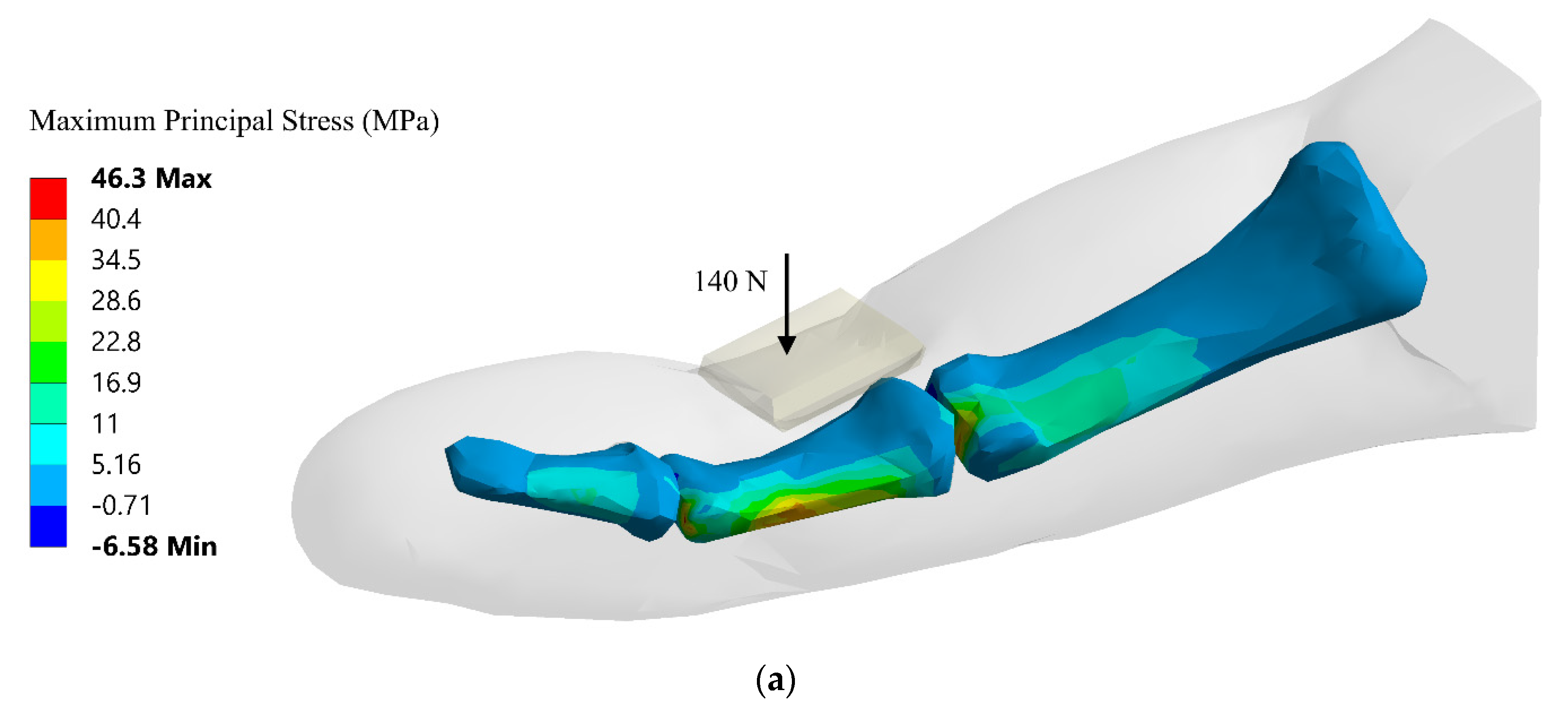
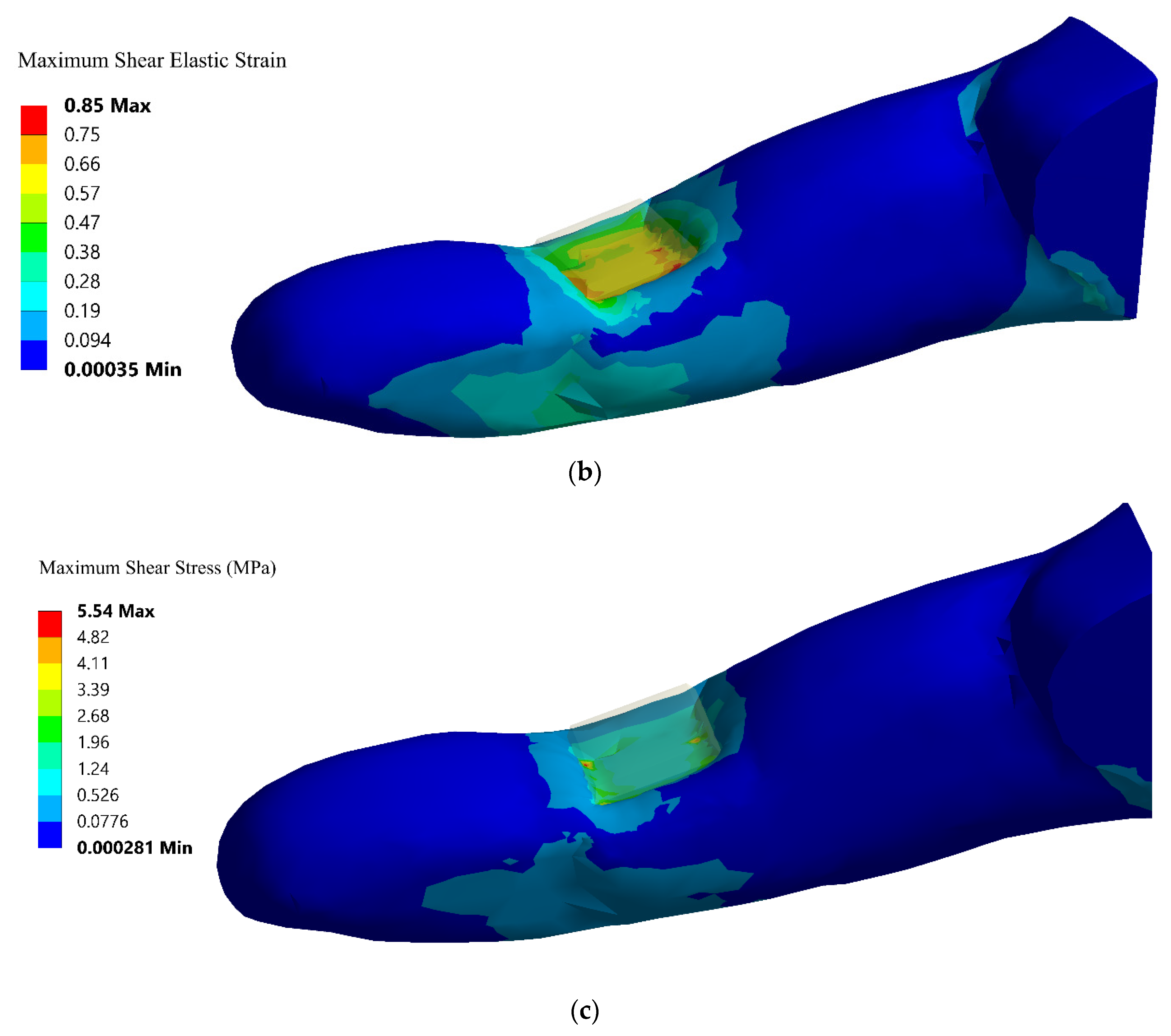
A quasi-static structural analysis was carried out on an index finger using ANSYS Static Structural by applying a constant force of 140 N to a flat 1.4 cm by 1.4 cm rigid metal surface with a 2 mm radius on all four edges. Boundary conditions used here were provided by ISO/TS15066 for determining the maximum qualitative values of quasi-static and transient contact between humans and the robot system. A pressure equal to the maximum permissible pressure in ISO/TS 15066 under quasi-static contact was applied on the flat part of the metal surface. The results of the quasi-static analysis, such as the maximum principal stresses and maximum elastic strain, were used as a benchmark for pain-onset threshold as per ISO/TS 15066, and extended Dynamic Analysis involving impact was carried out for accident scenarios. Whereas maximum force was defined as a force, a human body region could bear up to a pain onset level without minor injury. The values of stresses and elastic strain obtained as a result of quasi-static analysis were compared with hand strength threshold values. If the simulated stresses were equal or greater than threshold values, it was termed as a severe injury. On the other hand, if simulated stresses were less than threshold values, they were compared with the pain onset threshold. If they were equal to or greater than the pain onset threshold value, they were termed as unsafe interaction with moderate or minor injury; otherwise, interaction was considered as safe.

3.2. Setup for Dynamic Simulations

For modeling of transient contact/impact in ISO/TS 15066, the maximum permissible energy transfer was estimated as a function of the maximum force or maximum force values found as a result of the quasi-static test described in the previous section. As per ISO/TS 15066, the transient contact was modeled as a fully inelastic contact between a human body region and a robot with effective mass m R , which is given by:
m R = M 2 + m L
where M is the total mass of the moving parts of the robot and m L is the effective payload of the robot system. This is further used to estimate transient contact speed limits.
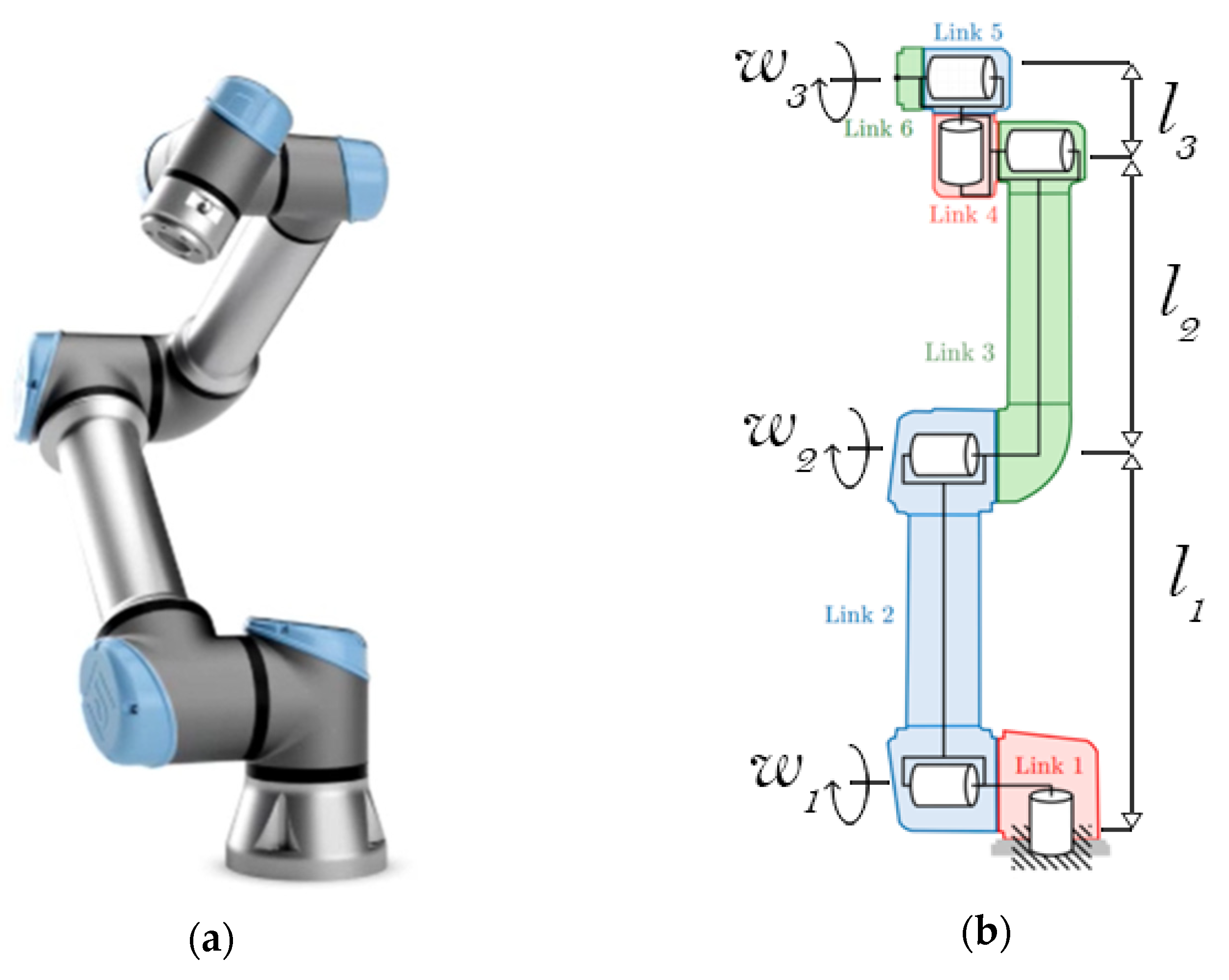
In this study, the distributed kinetic energy of the links was also considered. The mass of the actuators and the payload of the robot system were assumed to be point masses. The total rotational kinetic energy was calculated for the special case where the robot has its links extended for maximum reach and the shoulder joint, elbow joint, and wrist are operating at an equal angular velocity ( ω 1 = ω 2 = ω 3 ), as shown in Figure 2. Typically, robots are not operated in this configuration, with fully extended links, because of singularity concerns where the manipulator loses one or more degrees of freedom [35]. However, this configuration is suitable for the purpose of choosing an appropriate equivalent mass because this represents a harsh operating condition with high effective momentum and tool center point (TCP) velocity.
We define the link-length ratios as:
r 1 = l 1 L   ; r 2 = l 2 L   ; r 3 = l 3 L
where L = l 1 + l 2 + l 3 .
The total kinetic energy of the entire system is equated to the kinetic energy of an equivalent mass m R :
T t o t a l = 1 2 m R L ω 2
The resulting equivalent mass of the system is:
m R = m a r 1 2 + 2 r 1 + r 2 2 + 1 + m d 6 r 1 3 + 1 + 3 r 1 2 r 2 + 3 r 1 r 2 2 + m L
where m a is the mass of an actuator and m d is the total distributed mass of the links, less the actuators. In this study, the effective masses for Universal Robots UR3, UR5, and UR10 were estimated and used in subsequent analysis as examples of Small-, Medium-, and Heavy-Payload-capacity robots, respectively. This approach may be generalized to industrial robots with similar configurations.
Dynamic analysis was carried out for the full hand model as well as the index finger under different loading conditions, as summarized in Table 2. In all cases, a rigid cylindrical object, which represents the effective mass of the robot system, was given an initial velocity, which is the velocity of the end-effector of the robot.
The simulation end time was set at 50 ms. The intent was to capture the stress and strain characteristics as well as the contact forces during the initial moments of the impact. Average human reaction times are around 180 ms; however, unconscious reflex actions are typically much faster at around 50–80 ms [37]. It is assumed that the human subject will not be able to react to the impact stimuli before 50 ms, and the impact event will end as the human subject is expected to move their hand and finger away soon after 50 ms. Collaborative robots, such as the ABB Yumi and Universal Robotics UR10, employ torque sensors and force sensors embedded in joints for collision detection capability [38]. Therefore, the robot may apply the brakes once contact is detected by removing kinetic energy from the system. It may typically take 400 ms for the robot to stop completely; however, the reaction time of the typical HRC systems using lasers, Motion Tracking IMUs, or ultrasonic sensors is around 40–60 ms, which implies that the HRC system may initiate safety protocols after 50 ms [38]. Thus, a simulation time of 50 ms was chosen for all virtual experiments.

4. Analysis and Results

In the preceding section, the results of the quasi-static analysis are first presented to provide a benchmark. Next, results of the dynamic analysis are presented to establish robot speed limits and contact force limitations for low-, medium-, and heavy-payload-capacity robots.

4.1. Quasi-Static Analysis

In accordance with the quasi-static test conditions outlined in ISO/TS 15066, a 140 N force was applied on a small rigid plate, as shown in Figure 3, on the index finger model. The finger was assumed to be resting on a table or a test bench. It was, hence, supported on the opposite side, in the simulation. The results of the simulation are presented in Figure 3. The resulting shear elastic stress and strain in the finger skin/soft tissue were taken as a benchmark for pain onset and safe limits of operation in the dynamic analysis. The loading conditions of the quasi-static test resulted in only minor principal stresses in the bone.

4.2. Dynamic Analysis

Numerous virtual experiments were carried out on the digital model of the index finger and the hand to simulate dynamic impact with small-, medium-, and heavy-payload-capacity robots at different velocities and loading conditions. The purpose of the virtual experiments was validation, reinforcement, and extension of the technical standard. The maximum shear elastic strain and shear stress in the soft tissue, the maximum principal stresses developed in the bones, the contact forces at the point of impact, and the energy transfer between the robot and the human body were important outputs of the simulations. The mechanical strength of human cortical bone has been widely reported in the literature. In our analysis, principal stresses higher than 135 MPa were considered unsafe for the cortical bone [39], whereas the benchmark shear elastic stress and strain values were used for soft tissue.

4.2.1. Case I—Hyperextension

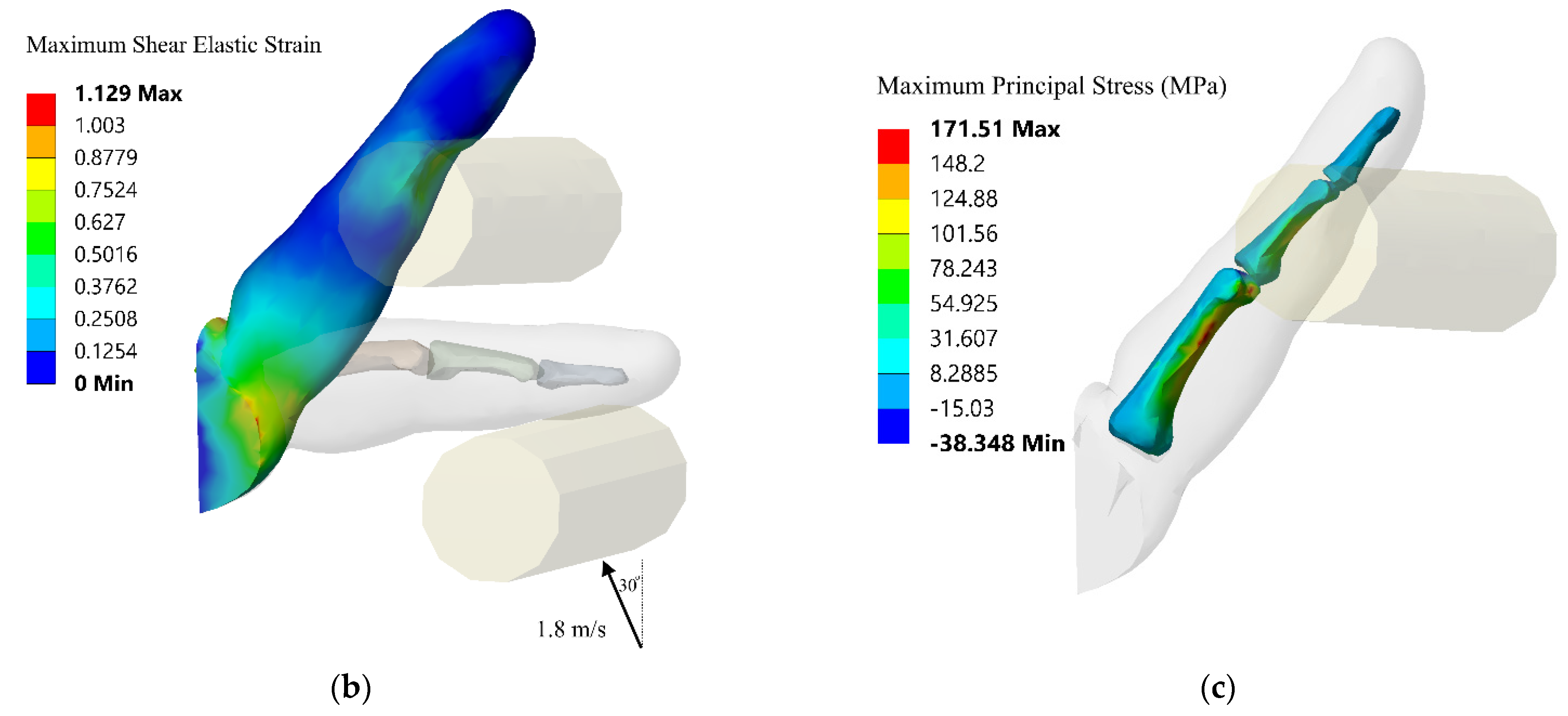
For this series of virtual experiments, hyperextension of the index finger was studied under different angles and velocities of impact. Figure 4 shows the hyperextension of the index finger under impact at 1.8 m/s velocity, at an angle of 30° from the vertical, by a robot with an effective mass of 3.6 kg (UR3 or similar robot). The shear strain exceeded the tissue damage threshold limit of 5.54 MPa at 30 ms. The maximum principal stresses developed in the bone exceeded the fracture threshold at 35 ms and reached a peak value of 171 MPa in the proximal phalange. The strain energy of the index finger reached a peak value of 4.0 Joules, which far exceeds the energy limit value of 0.49 J for the hands and fingers specified in ISO/TS 15066. The maximum contact force developed for this simulation was 273.3 N. Based on the total contact area, this corresponded to an average pressure of 127 N/cm2. This is lower than the maximum permissible pressures specified in ISO/TS 15066. However, the contact area of the cylindrical end effector was much higher than that of the plate used in the quasi-static case described earlier. Additionally, localized pressure at certain points may be higher than the permissible value even if the average pressure is lower.
As the end effector was not a sharp object and the motion of the finger was not severely constrained, it is understandable that the principal stress in the bone might have exceeded fracture limits close to the same time as the shear stress in the soft tissue exceeded permissible values.
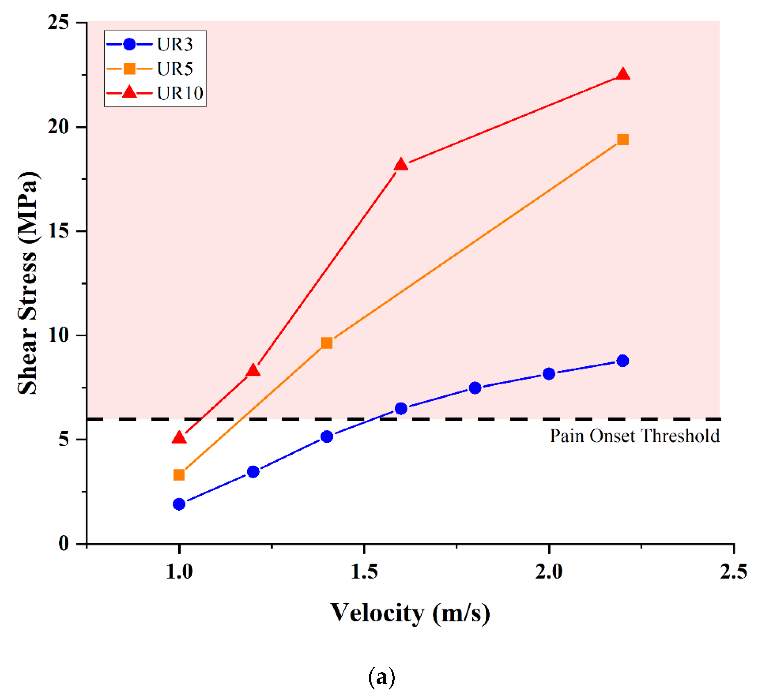
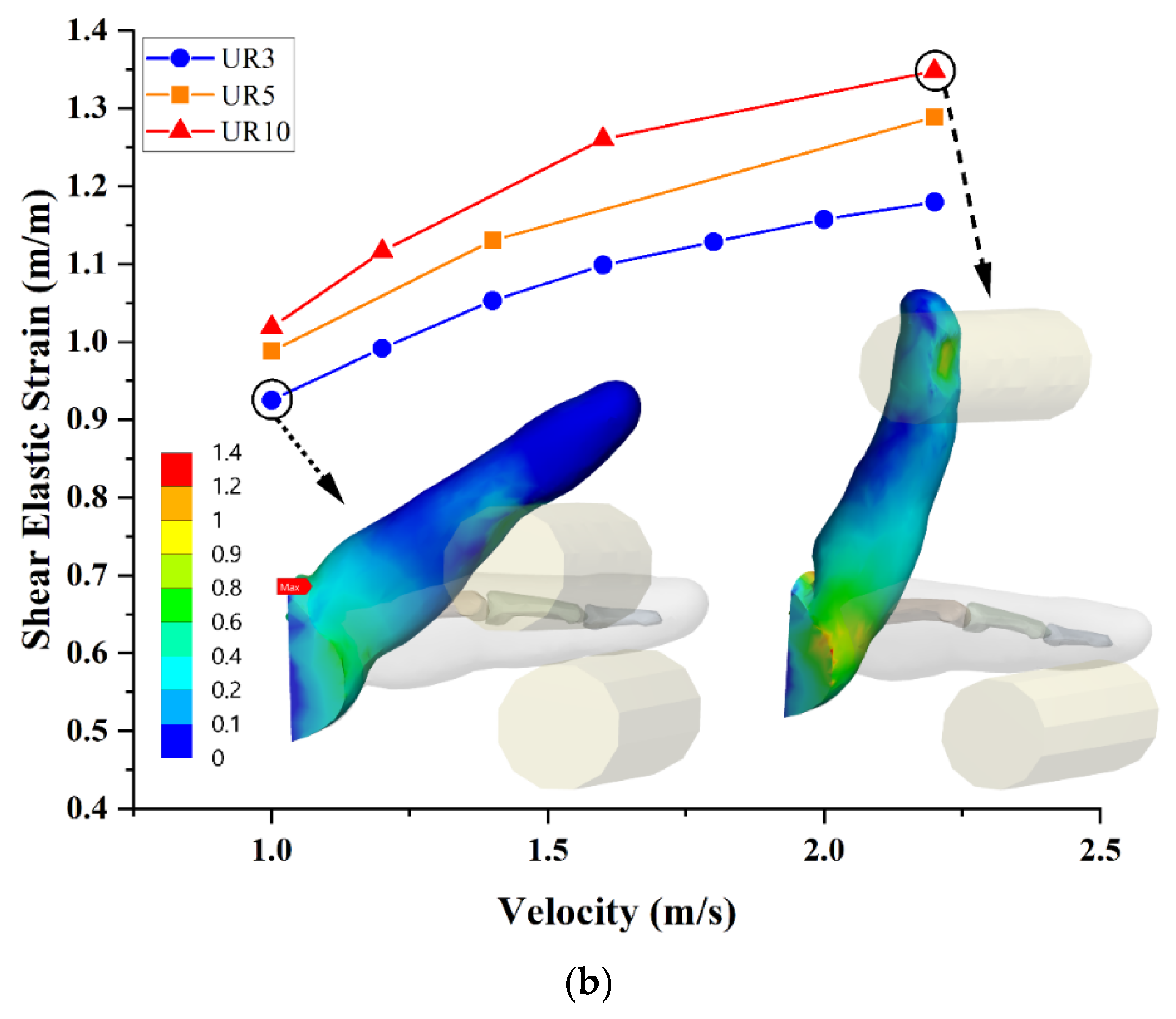
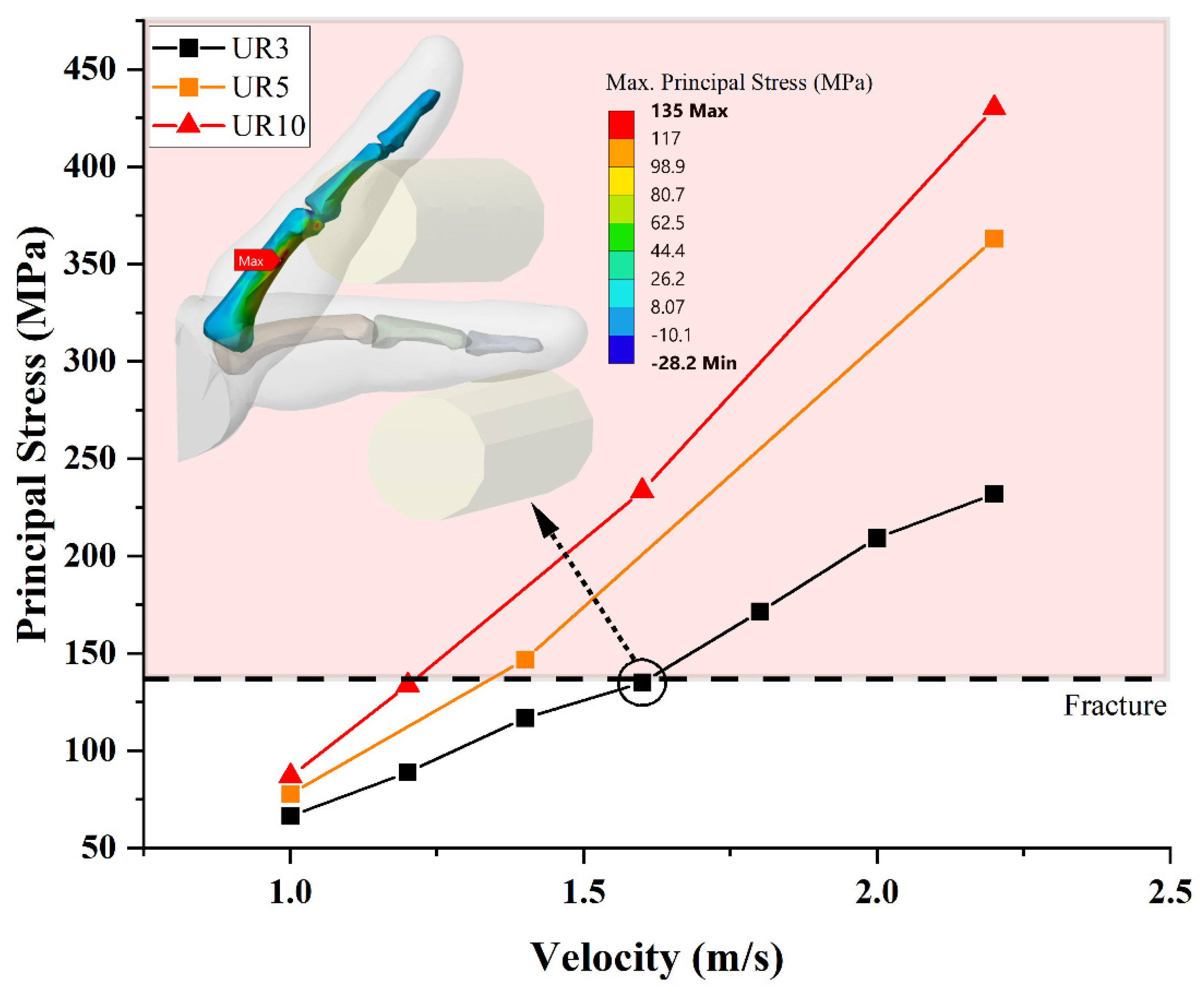
Virtual experiments were run for velocities between 1 m/s and 2.2 m/s. Figure 5 and Figure 6 show the maximum shear stress and maximum principal stresses developed in the tissue and bone, respectively. The results of the quasi-static benchmark test were used to highlight the pain onset threshold.
Another set of experiments with hyperextension was carried out, where the cylindrical end effector was given a velocity at different angles, with an initial velocity of 1.2 m/s and an end effector with an effective mass of 7.2 kg and 14.4 kg (corresponding to UR5 and UR10 or equivalent robots). It was observed that shear stress in the tissue as well as principal stress in the bones initially increased with an increase in the moment arm (Figure 7). When the angle of the initial velocity was directed at an angle of greater than 90 degrees, the end effector was effectively free to move past the finger without transferring much of its initial kinetic energy to the finger. As shown in Figure 8 and Figure 9, the shear strain and principal stress did not change markedly with an increase in robot effective mass under these conditions.

4.2.2. Case II—Flexion

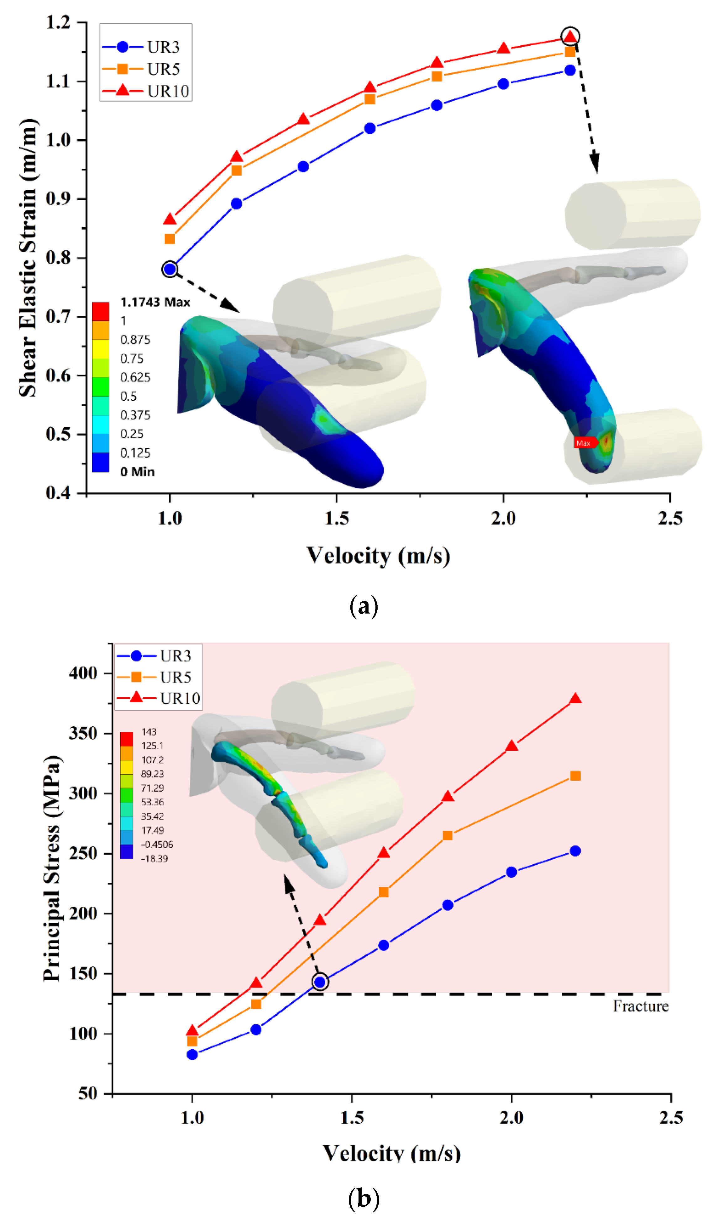
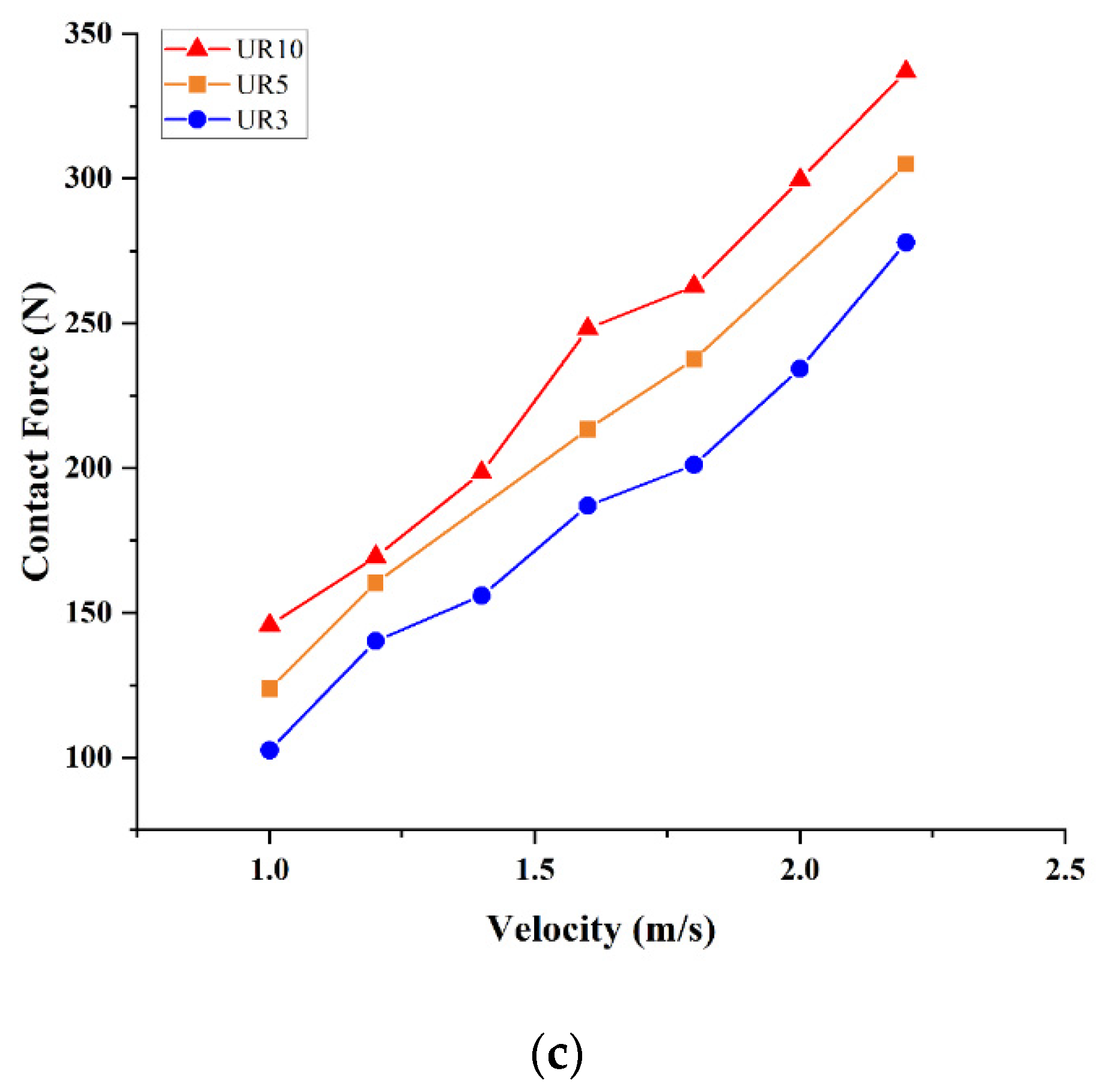
A summary of results is presented in Figure 10 for the set of experiments where the cylindrical end effector strikes the index finger from the top, coming vertically downward. The velocity of the end effector was varied from 1.0 m/s to 2.2 m/s, and experiments were repeated for effective mass values corresponding to small-, medium-, and heavy-payload-capacity robots (UR3, UR5, and UR10). Figure 10c shows the contact force at the point of contact of the end-effector with the index finger. Technical Specification ISO/TS 15066 specifies a maximum permissible force of 140 N for quasi-static contact, with a permissible force/pressure multiplier of 2 for transient contact. Our analysis suggests a strong correlation between contact forces and principal stresses. The results suggest that allowing a force multiplier of 2 resulted in exceedingly high principal stresses in the bones.

4.2.3. Case III—Abduction

Impact on a constrained finger from the side results in deformation in the abduction/adduction mode. The DIP and PIP revolute joints allow motion in the flexion/extension direction only. Only the MCP joint can act as a revolute joint within the prescribed limit in this mode of loading. These simulations, as shown in Figure 11, therefore, represent a much harsher scenario where tissue damage as well as bone fracture can occur at lower speeds to the constrained motion of the finger.
Technical Specification ISO/TS 15066 presents calculated transient speed limits as a function of robot effective mass using a simplified elastic collision model. Here, we validated and expanded upon those results using virtual experiments for low- and medium-payload-capacity robots (such as UR3 and UR5, respectively), and the results were further extended to heavy-payload-capacity robots. A summary of estimated speed limits for small-, medium-, and heavy-payload-capacity robots under the three loading modes is presented in Table 3. A high risk of fracture in the cortical bones was used as the failure criteria. The analysis suggests that high-payload-capacity robots (UR10 or equivalent) must be restricted to around 80% of the speed limits of low-payload-capacity robots (UR3 or equivalent) despite having 4 times more effective mass.
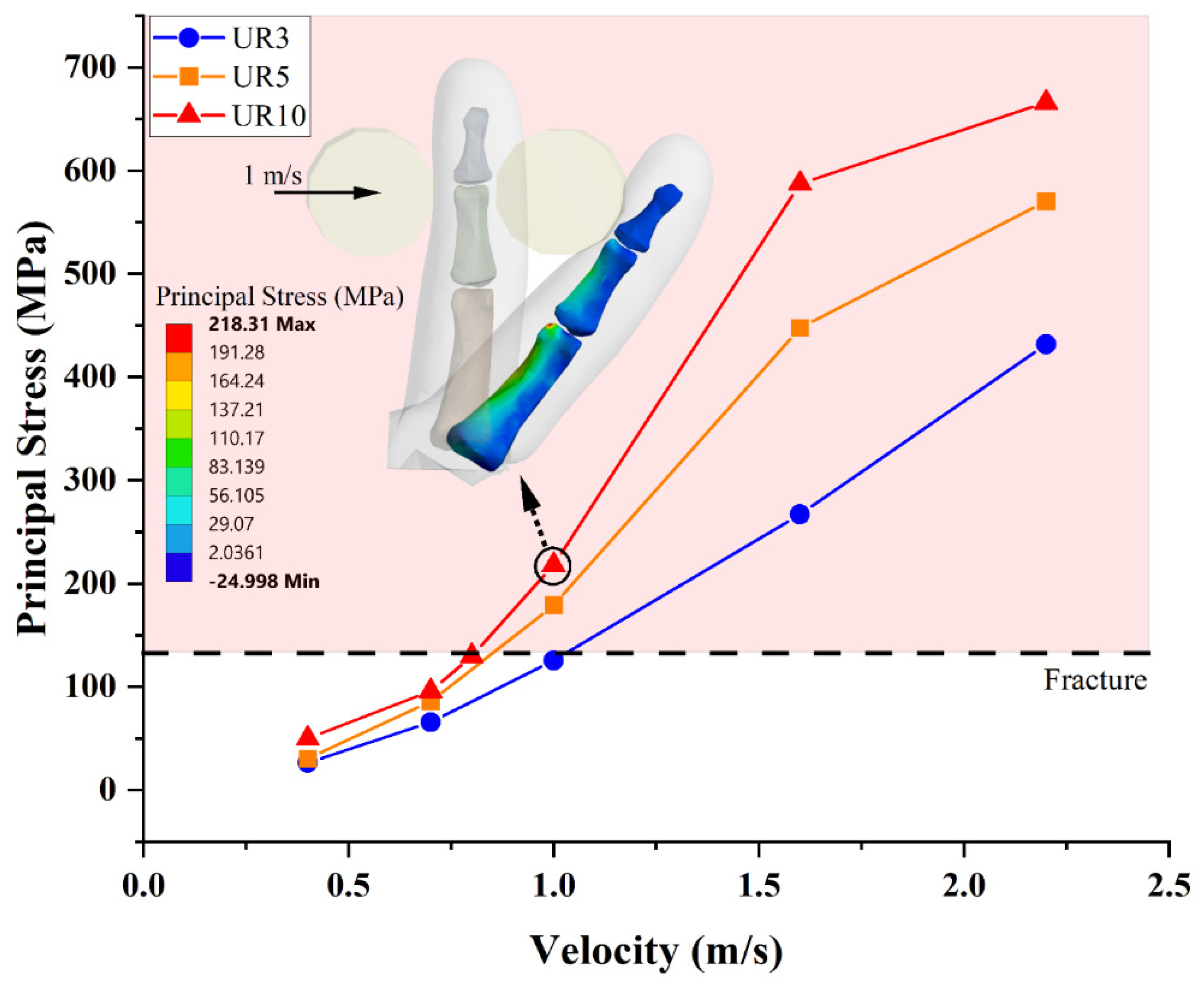
A comparison of the three loading conditions and three robot sizes with an impact velocity of 1000 mm/s is presented in Figure 12. The unsafe region of operation is marked in the figure. The figure highlights the importance of the mode of impact and robot payload capacity.

4.2.4. Case IV: Full Hand Model

A series of virtual experiments on the Full Hand Model was additionally carried out. In these simulations, the carpal bones were entirely removed, and fixed supports were added at the location of the carpometacarpal joints, and the location of the wrist. The removal of these joints results in reduced mobility, hence representing a harsher scenario where the motion of the hand is constrained at that location. In comparison with the index finger model, the full hand model can absorb more kinetic energy from the end effector owing to its increased bone and tissue mass.
Figure 13 shows the hyperextension of the digital hand model under impact at 1.0 m/s velocity, by a robot with an effective mass of 14.4 kg (UR10 or similar). The shear elastic strain exceeded the pain threshold limit of 0.85 m/m at 16 ms. The maximum principal stresses developed in the index finger was 104 MPa at 32 ms, around the time where the strain energy of the hand reached its maximum value of 6.17 Joules, i.e., maximum energy is transferred from the robot system to the hand. Overall, the maximum principal stress was observed in the little finger at the position shown in Figure 13d. For impact with a robot with an effective mass of 7.2 kg (UR5 or similar), the peak principal stress in the index finger dropped to 75 MPa at 24 ms. The digital hand model was able to absorb the kinetic energy of the end effector with relative ease.
Figure 14 shows the results for impact of the UR10 end effector at a velocity of 2.2 m/s under flexion. This represents a very harsh condition, with high velocity and high equivalent mass. The maximum principal stresses and shear elastic stress and strain were higher than the acceptable thresholds. The highest principal stress and equivalent (von-Mises) stress occurred at 21 ms from the start of impact, in the first metacarpal bone, in this scenario.

5. Discussion

As addressed above, HRC requires a seamless integration of humans and robots in a shared workspace in industry, which gives rise to new risks of worker accidents that need to be addressed. The approach to mitigate these risks is discussed including the quantification level of injury by collision. Keeping in view the environment whose main objective is to dispense safe HRC, several studies have analyzed the result of human–robot collision on the human body. This question is addressed from two different opinions, pain onset level estimation and quantifying the level of injury. This paper presents a first analysis and simulation setup to assess impact measurements and damage in the smart factory context for accidents due to HRC. However, this study is restricted to the human hand and focuses on different loading conditions on the index finger.
A finite element methods approach is implemented for the simulations that are accomplished within this research. FEM is basically the discretization of spatial structures to anticipate a set of PDEs (partial differential equations) and the solution is carried out more easily with the proposed boundary conditions. To assess the impact level of severity on the human body, the FEM is widely used in the biomechanics field. A three-dimensional model of a human index finger is constructed by using 3D CAD software. The 3D model is consisted of metacarpal phalanx, distal phalanx, and MCP joint and DIP joints. Joints are modeled as revolute joints to introduce one degree of freedom (extension-flexion). Bone is covered with soft tissue. Then, the CAD model is imported in ANSYS software, to analyze the stress distribution in the hand according to the boundary conditions provided in the ISO/TS 15066. Severity of impact is assessed based on the deep somatic pain onset level that a human can tolerate. There are various techniques available in the literature where pain onset level is studied using pinch actuators composed of pneumatic cylinders. Such cylinders can apply localized loads to various body parts to find tolerable forces. In this research, the contact force, principal stresses, and shear stresses are obtained under different loading conditions. A quasi-static analysis is first performed where a constant force not exceeding the maximum permissible force specified in ISO/TS 15066 is applied to the index finger. This results in a maximum elastic strain of 0.85 and a maximum shear stress of 5.54 MPa in the soft tissue. The maximum principal stresses developed in the bones are relatively low, at 46.3 MPa. These results provide benchmark values for shear stress and stress in soft tissue, which are used in subsequent dynamic analysis for impact.
ISO/TS 15066 estimates permissible transient contact velocities using a simplified inelastic collision model. In this study, the angle, direction, and location of the impact, together with geometry and material properties of the digital hand/index finger model, are used to predict permissible robot speeds under different loading conditions for low- and medium-payload-capacity robots, and then extended to heavy-payload-capacity robots. With the ISO/TS 15066 currently under review, further research into biomechanical modeling using the FEM may pave the way for its extension to heavy-payload-capacity robots. In this study, it is observed that the results are strongly dependent on the loading conditions, i.e., the velocity, direction, and location of impact. One of the primary barriers to widespread adoption of Collaborative Robots is the perceived unsafe feeling of operators, especially for heavy-payload-capacity robots [40]. In addition to robot characteristics, factors such as the location of operators and the presence of physical obstacles add to the hazard of human–robot collaboration [41]. An expected result, which is evident from the virtual experiments, is that it is undesirable to have constraints in the permissible motion of the hand. This suggests that HRC systems should designed in a way that the intersection of human hand and robot trajectories is expected in open spaces where there are no constraints on the motion of any joints. Furthermore, chances of impact that cause deformation in the abduction/adduction mode should be minimized. Under hyperextension and flexion, low-payload-capacity robots can have speed limits up to 1530 mm/s and 1360 mm/s, respectively, whereas heavy-payload-capacity robots must be restricted to 1200 mm/s and 1150 mm/s, respectively. The results show that damage severity varies with the velocity, point of impact, and direction. There are many studies on human pose estimation and motion prediction to develop safe HRC systems [10,42]. In a worst-case scenario, where impact is unavoidable, the robot control system may utilize motion and damage severity prediction to implement a policy that minimizes injury.
The preceding discussion suggests that the initial resting position of the hand/index finger may also affect the severity of damage. Moreover, human cortical bone is a very complicated material with mechanical properties specified by their microstructure and orientation, which acclimatizes to unceasingly altered environments and loading conditions. Due to practical consequences, the mechanical properties may slightly vary for cortical bone and skin. The effects of aging can cause variations in the ultimate tensile stress as it is decreased at a rate of about five percent per decade [43]. Additionally, due to the elastic anisotropy property, the human cortical bone is stiffer in the longitudinal direction. Compression strength is higher than tensile strength because of the equivalent modulus in compression and tension.
In future studies, a more robust material model will be used, where fingernails may be included, and human bones may be modeled by considering their anisotropy and including both the cortical bone and cancellous bone with different layers of skin. The effect of the initial resting posture of the hand and the effect of using safety gloves can also be considered. Another future direction of our work is to extend this study to different body parts such as elbows and shoulders, with the aim of extending the results to human-centered safety analysis of cyber-physical systems.

6. Conclusions

The main goal of HRC is the safe collaboration of human worker and robot in different applications on the industrial floor in the shared workspace without passive safety controls. As the number of collaborative robots grows, the risk of accidents is expected to increase, keeping in mind that a large number of conventional, non-collaborative robots are heavy-payload-capacity robots working today in industry worldwide. Their replacement is only possible with intelligent collaborative counterparts, meaning a higher magnitude of risk involved. Thus, in this scenario, it is imperative to build digital twin models of industrial processes with multiphysics capabilities to study multifaceted issues. HRC is one such industrial process involved in automatic and semi-automatic intelligent manufacturing where the occupational safety concern is the largest issue that is limiting the emergence of collaborative heavy-payload-capacity robots to the factory floor. This safety aspect can be studied in detail with such models developed in this paper where the interactions are further modeled and simulated for extreme conditions and cases.
The resulting interactions in this case may lead to accidents causing minor- to severe-level injuries depending upon the level of impact. In this paper, a human hand is modeled to assess the contact loading stress and strain measurements and numerical damage projections in a smart factory context using a commercially available FE software ANSYS. The results are used for the purpose of validation, reinforcement, and extension of the Technical Standard TS/15066. A quasi-static analysis is first performed to benchmark stress and strain values. Dynamic analysis is subsequently performed to establish robot speed limits and contact force limitations for low-, medium-, and heavy-payload-capacity robots.
The current study will form the basis to extend the impact analysis in collaborating with heavy-payload-capacity robots. The point of interest is the level of impact and its predicted outcome on different body parts in terms of pain and onset of injuries threshold, therefore knowing more about the limits for safe use of heavy-payload-capacity robots in a collaborative manner.

Author Contributions

Conceptualization, A.K. and J.P.; methodology, W.A.L.; software, S.R. and U.A.; validation, U.A., T.K. and W.A.L.; formal analysis, U.A. and W.A.L.; investigation, A.K. and T.K.; resources, J.P. and A.K.; data curation, S.R.; writing—original draft preparation, S.R. and U.A; writing—review and editing, U.A., W.A.L. and A.K.; visualization, A.K., W.A.L. and J.P.; supervision, A.K. and W.A.L.; project administration, W.A.L.; funding acquisition, A.K. and J.P. All authors have read and agreed to the published version of the manuscript.

Funding

This research received no external funding.

Institutional Review Board Statement

Not applicable.

Informed Consent Statement

Not applicable.

Data Availability Statement

Not applicable.

Conflicts of Interest

The authors declare no conflict of interest.

Nomenclature

U Strain Energy Potential m R Robot Effective Mass
λ i ¯ α i Principal stretches m L Robot effective payload
N No. of terms in hyperelastic model l 1 , l 2 , l 3 Robot link lengths
μ i , α i Experimentally determined material parameters r 1 , r 2 , r 3 Robot link-length Ratios
D i Compressibility L Sum of robot link lengths
J e l Elastic Volume Ratio m a Robot actuator mass
M Total mass of robot moving parts m d Distributed mass of robot links

References

  1. Executive Summary World Robotics 2018 Industrial Robots (No Date). Available online: https://ifr.org/downloads/press2018/Executive_Summary_WR_2018_Industrial_Robots.pdf (accessed on 19 March 2022).
  2. Executive Summary World Robotics 2020 Industrial Robots (No Date). Available online: https://ifr.org/img/worldrobotics/Executive_Summary_WR_2020_Industrial_Robots_1.pdf (accessed on 4 April 2022).
  3. Kriaa, S.; Pietre-Cambacedes, L.; Bouissou, M.; Halgand, Y. A Survey of Approaches Combining Safety and Security for Industrial Control Systems. In Reliability Engineering and System Safety; Elsevier Ltd.: Amsterdam, The Netherlands, 2015; pp. 156–178. [Google Scholar] [CrossRef]
  4. Khalid, A.; Kirisci, P.; Ghrairi, Z.; Pannek, J.; Thoben, K.D. Safety Requirements in Collaborative Human–Robot Cyber-Physical System. In Lecture Notes in Logistics; Springer Science and Business Media: Berlin, Germany, 2017; pp. 41–51. [Google Scholar] [CrossRef]
  5. Vysocky, A.; Novak, P. Human—Robot collaboration in industry. MM Sci. J. 2016, 2016, 903–906. [Google Scholar] [CrossRef]
  6. Rüßmann, M.; Lorenz, M.; Gerbert, P.; Waldner, M.; Justus, J.; Engel, P.; Harnisch, M. Industry 4.0: The Future of Productivity and Growth in Manufacturing Industries. Boston Consult. Group 2015, 9, 54–89. [Google Scholar]
  7. Islam, S.O.B.; Lughmani, W.A.; Qureshi, W.S.; Khalid, A.; Mariscal, M.A.; Garcia-Herrero, S. Exploiting visual cues for safe and flexible cyber-physical production systems. Res. Artic. Adv. Mech. Eng. 2019, 11, 1–13. [Google Scholar] [CrossRef]
  8. Thumm, J.; Althoff, M. Provably Safe Deep Reinforcement Learning for Robotic Manipulation in Human Environments. In Proceedings of the 2022 International Conference on Robotics and Automation (ICRA), Philadelphia, PA, USA, 23–27 May 2022. [Google Scholar]
  9. Liu, Q.; Liu, Z.; Xiong, B.; Xu, W.; Liu, Y. Deep reinforcement learning-based safe interaction for industrial human-robot collaboration using intrinsic reward function. Adv. Eng. Inform. 2021, 49, 1360. [Google Scholar] [CrossRef]
  10. Choi, S.H.; Park, K.-B.; Roh, D.H.; Lee, J.Y.; Mohammed, M.; Ghasemi, Y.; Jeong, H. An integrated mixed reality system for safety-aware human-robot collaboration using deep learning and digital twin generation. Robot. Comput. Integr. Manuf. 2022, 73, 102258. [Google Scholar] [CrossRef]
  11. Khalid, A.; Kirisci, P.; Khan, Z.H.; Ghrairi, Z.; Thoben, K.-D.; Pannek, J. Security framework for industrial collaborative robotic cyber-physical systems. Comput. Ind. 2018, 97, 132–145. [Google Scholar] [CrossRef]
  12. Lasota, P.A.; Rossano, G.F.; Shah, J.A. Toward Safe Close-Proximity Human-Robot Interaction with Standard Industrial Robots. In 2014 IEEE International Conference on Automation Science and Engineering (CASE); IEEE: Piscataway, NJ, USA, 2014; pp. 339–344. [Google Scholar] [CrossRef]
  13. Cherubini, A.; Passama, R.; Crosnier, A.; Lasnier, A.; Fraisse, P. Collaborative manufacturing with physical human-robot interaction. Robot. Comput. Integr. Manuf. 2016, 40, 1–13. [Google Scholar] [CrossRef]
  14. Chinniah, Y. Robot Safety: Overview of Risk Assessment and Reduction. Adv. Robot. Autom. 2016, 5, 139. [Google Scholar] [CrossRef]
  15. Pellegrinelli, S.; Moro, F.L.; Pedrocchi, N.; Tosatti, L.M.; Tolio, T. A probabilistic approach to workspace sharing for human–robot cooperation in assembly tasks. CIRP Ann. 2016, 65, 57–60. [Google Scholar] [CrossRef]
  16. Jiang, B.C.; Gainer, C.A. A cause-and-effect analysis of robot accidents. J. Occup. Accid. 1987, 9, 27–45. [Google Scholar] [CrossRef]
  17. Fryman, J.; Matthias, B. Safety of Industrial Robots: From Conventional to Collaborative Applications. In Proceedings of the ROBOTIK 2012 7th German Conference on Robotics, Munich, Germany, 21–22 May 2012; pp. 1–5. [Google Scholar]
  18. Accident Search Results Page|Occupational Safety and Health Administration (No Date). Available online: https://www.osha.gov/pls/imis/AccidentSearch.search?acc_keyword=%22Robot%22&keyword_list=on (accessed on 4 April 2022).
  19. Oberer, S.; Malosio, M.; Schraft, R.D. Investigation of robot human impact. VDI Berichte 1956 2006, 15, 87. [Google Scholar]
  20. Khalid, A.; Kirisci, P.; Ghrairi, Z.; Thoben, K.D.; Pannek, J. Towards implementing Safety and Security Concepts for Human-Robot Collaboration in the context of Industry 4.0. In Proceedings of the 39th International MATADOR Conference on Advanced Manufacturing, Manchester, UK, 17–19 August 2017. [Google Scholar]
  21. Suita, K.; Yamada, Y.; Tsuchida, N.; Imai, K.; Ikeda, H.; Sugimoto, N. A Failure-to-Safety “Kyozon” System with Simple Contact Detection and Stop Capabilities for Safe Human-Autonomous Robot Coexistence. In Proceedings of the 1995 IEEE International Conference on Robotics and Automation, Nagoya, Japan, 21–27 May 1995; IEEE: Piscataway, NJ, USA, 1995; Volume 3, pp. 3089–3096. [Google Scholar] [CrossRef]
  22. Povse, B.; Koritnik, D.; Kamnik, R.; Bajd, T.; Munih, M. Industrial Robot and Human Operator Collision. In Proceedings of the 2010 IEEE International Conference on Systems, Man and Cybernetics, Istanbul, Turkey, 10–13 October 2010; IEEE: Piscataway, NJ, USA, 2010; pp. 2663–2668. [Google Scholar] [CrossRef]
  23. Haasper, C.; Junge, M.; Ernstberger, A.; Brehme, H.; Hannawald, L.; Langer, C.; Nehmzow, J.; Otte, D.; Sander, U.; Krettek, C.; et al. The Abbreviated Injury Scale (AIS). Options and problems in application. Unfallchirurg 2020, 113, 366–372. [Google Scholar] [CrossRef] [PubMed]
  24. ISO 15066; Robots and Robotic Devices-Collaborative Robots. International Organisation of Standardisation: Genewa, Switzerland, 2016.
  25. Mallon, W.J.; Brown, H.R.; Nunley, J.A. Digital ranges of motion: Normal values in young adults. J. Hand Surg. 1991, 16, 882–887. [Google Scholar] [CrossRef]
  26. Joodaki, H.; Panzer, M.B. Skin mechanical properties and modeling: A review. Proc. Inst. Mech. Eng. Part H J. Eng. Med. 2018, 232, 323–343. [Google Scholar] [CrossRef]
  27. Harih, G.; Tada, M. Development of a feasible finite element digital human hand model. DHM Posturography 2019, 273–286. [Google Scholar] [CrossRef]
  28. Shergold, O.A.; Fleck, N.A. Mechanisms of deep penetration of soft solids, with application to the injection and wounding of skin. Proc. R. Soc. Lond. Ser. A Math. Phys. Eng. Sci. 2004, 460, 3037–3058. [Google Scholar] [CrossRef]
  29. Kamper, D.G.; George Hornby, T.; Rymer, W.Z. Extrinsic flexor muscles generate concurrent flexion of all three finger joints. J. Biomech. 2002, 35, 1581–1589. [Google Scholar] [CrossRef]
  30. Completo, A.; Duarte, R.; Fonseca, F.; Simões, J.; Ramos, A.; Relvas, C. Biomechanical evaluation of different reconstructive techniques of proximal tibia in revision total knee arthroplasty: An in-vitro and finite element analysis. Clin. Biomech. 2013, 28, 291–298. [Google Scholar] [CrossRef]
  31. Luo, Y.; Wang, Y.; Tai, B.L.; Chen, R.K.; Shih, A.J. Bone geometry on the contact stress in the shoulder for evaluation of pressure ulcers: Finite element modeling and experimental validation. Med. Eng. Phys. 2015, 37, 187–194. [Google Scholar] [CrossRef]
  32. Aubert, K.; Germaneau, A.; Rochette, M.; Ye, W.; Severyns, M.; Billot, M.; Rigoard, P.; Vendeuvre, T. Development of Digital Twins to Optimize Trauma Surgery and Postoperative Management. A Case Study Focusing on Tibial Plateau Fracture. Front. Bioeng. Biotechnol. 2021, 9, 722275. [Google Scholar] [CrossRef]
  33. Bahraminasab, M.; Bin Sahari, B.; Edwards, K.; Farahmand, F.; Hong, T.S.; Arumugam, M.; Jahan, A. Multi-objective design optimization of functionally graded material for the femoral component of a total knee replacement. Mater. Des. 2014, 53, 159–173. [Google Scholar] [CrossRef]
  34. Maas, S.A.; Ellis, B.J.; Rawlins, D.S.; Weiss, J.A. Finite Element Simulation of Articular Contact Mechanics with Quadratic Tetrahedral Elements HHS Public Access. J. Biomech. 2016, 49, 659–667. [Google Scholar] [CrossRef] [PubMed]
  35. Elsheikh, A.H.; Showaib, E.A.; Asar, E.M. Artificial Neural Network Based Forward Kinematics Solution for Planar Parallel Manipulators Passing through Singular Configuration. Adv. Robot. Autom. 2013, 106, 2. [Google Scholar]
  36. UR5 Collaborative Robot Arm|Flexible and Lightweight Cobot (No Date). Available online: https://www.universal-robots.com/products/ur5-robot/ (accessed on 23 March 2022).
  37. Welford, W.T.; Brebner, J.M.; Kirby, N. Reaction Times; Welford, A.T., Ed.; Academic Press: London, UK, 1980. [Google Scholar]
  38. Khalid, A.; Kirisci, P.; Ghrairi, Z.; Thoben, K.D.; Pannek, J. A methodology to develop collaborative robotic cyber physical systems for production environments. Logist. Res. 2016, 9, 1–15. [Google Scholar] [CrossRef]
  39. Hart, N.H.; Nimphius, S.; Rantalainen, T.; Ireland, A.; Siafarikas, A.; Newton, R.U. Mechanical basis of bone strength: Influence of bone material, bone structure and muscle action. J. Musculoskelet. Neuronal Interact. 2017, 17, 114. [Google Scholar]
  40. Berx, N.; Decré, W.; Pintelon, L. Examining the Role of Safety in the Low Adoption Rate of Collaborative Robots. Procedia CIRP 2022, 106, 51–57. [Google Scholar] [CrossRef]
  41. Khalid, A.; Khan, Z.H.; Idrees, M.; Kirisci, P.; Ghrairi, Z.; Thoben, K.-D.; Pannek, J. Understanding vulnerabilities in cyber physical production systems. Int. J. Comput. Integr. Manuf. 2021, 35, 569–582. [Google Scholar] [CrossRef]
  42. Fan, J.; Zheng, P.; Li, S. Vision-based holistic scene understanding towards proactive human–robot collaboration. Robot. Comput. Integr. Manuf. 2022, 75, 102304. [Google Scholar] [CrossRef]
  43. McCalden, R.W.; A McGeough, J.; Barker, M.B.; Court-Brown, C.M. Age-related changes in the tensile properties of cortical bone. The relative importance of changes in porosity, mineralization, and microstructure. J. Bone Jt. Surg. Am. Vol. 1993, 75, 1193–1205. [Google Scholar] [CrossRef]
Figure 1. (a) FE Model of the human hand; (b) FE Model of the Index Finger.
Applsci 13 01957 g001
Figure 2. (a) Commercial collaborative robot for accident scenarios [36]. (b) Robot Configuration for calculation of equivalent mass.
Applsci 13 01957 g002
Figure 3. Quasi-Static test. (a) Maximum Principal Stress (b) Maximum Shear Elastic Strain (c) Maximum Shear Stress.
Applsci 13 01957 g003aApplsci 13 01957 g003b
Figure 4. (a) Results for hyperextension of index finger; (b) Maximum Shear Elastic Strain; (c) Maximum Principal Stress.
Applsci 13 01957 g004aApplsci 13 01957 g004b
Figure 5. Hyperextension as a function of end effector velocity and robot effective mass, with contour results at the points shown: (a) Maximum Shear Stress; (b) Maximum Shear Elastic Strain.
Applsci 13 01957 g005aApplsci 13 01957 g005b
Figure 6. Maximum Principal Stress as a function of end effector velocity and effective mass, with contour results at the indicated point.
Applsci 13 01957 g006
Figure 7. Maximum Principal Stresses vs. Angle of Impact, UR5 and UR10, with contour results at the points shown.
Applsci 13 01957 g007
Figure 8. Shear Elastic Strain under hyperextension for effective masses (a) 3.6, (b) 7.2, and (c) 14.4 kg.
Applsci 13 01957 g008
Figure 9. Principal stress under hyperextension for effective masses (a) 3.6, (b) 7.2, and (c) 14.4 kg.
Applsci 13 01957 g009
Figure 10. Flexion as a function of end effector velocity and effective mass, with contour results at the points shown: (a) Elastic Strain, (b) Principal Stress, and (c) Contact Force.
Applsci 13 01957 g010aApplsci 13 01957 g010b
Figure 11. Abduction: Maximum Principal Stress.
Applsci 13 01957 g011
Figure 12. (a) Maximum Principal Stress (MPa); (b) Maximum Shear Elastic Strain.
Applsci 13 01957 g012
Figure 13. Impact of UR10 end effector at velocity of 1 m/s under hyperextension. (a) Impact Geometry, (b) Energy Transfer, (c) Shear Elastic Strain, and (d) Principal Stress.
Applsci 13 01957 g013
Figure 14. Impact of UR10 end effector at velocity of 2.2 m/s under flexion. (a) Impact Geometry, (b) Shear Elastic Strain, (c) Principal Stress, and (d) von-Mises Stress.
Applsci 13 01957 g014
Table 1. Material properties of human hand bone and soft tissue.
Bone
Young’s Modulus17 GPa
Poisson’s Ratio0.3
Density, ρ 2000 kg/m3
Skin
Material Parameter, α 1 9
Material Parameter, μ 1 0.11 MPa
Compressibility, D 1 2 MPa−1
Density, ρ 1040 kg/m3
Joints
Stiffness142 N·mm/°
Damping2.4 N·mm·s/°
Table 2. Design of Virtual Experiments.
Robot Size/Effective MassVelocity RangeMode of Loading
UR3; Effective Mass: 3.6 kg1000 to 2200 mm/sFlexion
UR5; Effective Mass: 7.2 kgHyper-Extension
UR10; Effective Mass: 14.4 kgAbduction
Table 3. Summary of Robot Speed Limits.
S#Robot SizeHyperextensionFlexionAbduction
1UR3; Effective Mass: 3.6 kg1520 mm/s1360 mm/s1000 mm/s
2UR5; Effective Mass: 7.2 kg1300 mm/s1250 mm/s850 mm/s
3UR10; Effective Mass: 14.4 kg1200 mm/s1150 mm/s800 mm/s
Disclaimer/Publisher’s Note: The statements, opinions and data contained in all publications are solely those of the individual author(s) and contributor(s) and not of MDPI and/or the editor(s). MDPI and/or the editor(s) disclaim responsibility for any injury to people or property resulting from any ideas, methods, instructions or products referred to in the content.