Abstract
In this study, we propose and analyze three designs of a novel aerial system that aims for autonomous firefighting missions in the body or border of water areas. In such areas, it is difficult and even dangerous for human firefighters, and firefighting robots, to approach and put out the fire. Thus, the systems proposed in this paper make use of the available water source not only for suppressing the fire, but also for propelling and maneuvering themselves. The three designs are different in their ways of actuating, namely flow rate control, nozzle rotation control, and weight distribution control. The designs are first introduced. Then, mathematical models are formulated and reveal the motion characteristics of each system. A linear control framework is developed and implemented for all of them. Simulation studies were conducted to verify their motion performance and subsequently, to select the best solution. The results indicate that the weight distribution control system struggled to follow the required reference while the two other designs both provided adequate maneuverability. The nozzle rotation control system is the better one, with greater tracking results of the head part and smaller fluctuations of the water hose.
1. Introduction
The use of remote-controlled robots and unmanned vehicles in hazardous environments has been attracting much interest. In such environments, human exposure would either represent a threat to life or a long-term health concern. In particular, in a firefighting mission, firefighters have to carry heavy hoses and tools over a significant distance and under extreme conditions of heat, smoke, and structures that could collapse at any moment. Over the past decade, terrestrial robots and multi-propeller aerial vehicles have been deployed in these missions. Unfortunately, many of their characteristics make their use may ineffective.
In terms of terrestrial firefighting robots, the most preferable configuration is in the form of an all-terrain tracked utility vehicle. They usually have a highly durable yet customizable chassis so that they can carry different tools for different tasks: firefighting, heavy load transportation, taking measurements, protective water shield creation, etc. For solely firefighting purposes, the robots equip with a motorized water cannon and carry a fire hose conveying water from a fire hydrant. These robots can be operated remotely, battling flames from close distances or in difficult locations, tunnels and explosives depots, for example. Commercial products, such as Colossus and Rhyno Protect robots from Shark Robotics (La Rochelle, France) [1], Thermite robots from Howe & Howe Technologies (Waterboro, ME, USA) [2], and TEC800 from Angatec (Perigny, France) [3], have been developed and deployed. However, moving on uneven terrain, for example, a pile of rubble, is not easy, not to mention the robot also has to pull a large fire hose with water. For fire events in high places, water areas, and intricate structures, a terrestrial robot cannot approach. Then, the only solution is to shoot a powerful jet of water from a far distance, which is not only ineffective, but can also cause property damage. Other types of terrestrial firefighting robots have also been studied, such as legged robots [4,5], snake robots [6], and even humanoid robots [7,8], but practicability is still low.
An aerial firefighting system can overcome the above problems easily. Hence, multi-propeller aerial vehicles have been used to carry firefighting tools and perform firefighting missions. The flight maneuverability and flexibility of the vehicles allow them to reach almost every fire location. The aerial systems also have a high-ground advantage over the flame, thus improving the fire suppression efficiency. They also vary in design, fire extinguishing material, and firefighting tactics. Numerous related problems have been studied [9,10,11,12,13], and prototypes have been tested [14,15,16,17]. However, the operation of these systems is still limited in range and duration, and the size of the fire they can fight. For larger-scale fires, multiple systems must cooperate to perform the task efficiently. Especially, the airflow generated by the propellers may also blow the flames into neighboring areas. Some systems, such as [17], avoid this problem by using a long extinguishing nozzle and battling the flame from a distance. Eventually, this reduced the maneuverability of the system. High-speed rotating blades are also not a good choice in terms of reducing human injury or property damage.
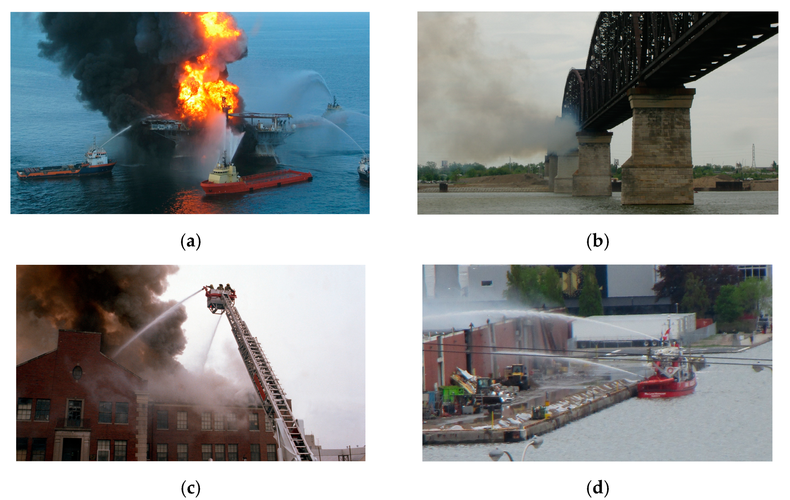
Therefore, in this study, we propose the use of novel firefighting systems that take advantage of aerial ones and overcome the limitation of the multi-propeller configuration. Instead, we use waterpower, not only to put out the fire, but also to propel and maneuver the systems. The systems are aimed to battle fire events in the body or border of water areas, such as on a narrow bridge, in a crowded harbor, and over a boat on the sea. The enormous amount of water in these areas allows water-powered systems to operate successfully. Meanwhile, it is difficult, or in some cases impossible, for human firefighters and other firefighting robots to access and perform their duties. The proposed systems could also use water from fire hydrants and could therefore be extended to fire accidents in buildings or cities. Figure 1 illustrates some of these operating scenarios.

Figure 1.
Application scenarios of the proposed systems: (a) Boat fire; (b) Fire on a bridge; (c) Fire in medium-rise buildings; (d) Fire at the border of a water area.
We consider three novel designs of the water-powered aerial firefighting system with different motion characteristics. Each has a water pump to pressurize water and a flexible hose to convey the water to a nozzle assembly to generate thrust. An additional nozzle is used to spray water for firefighting. The three designs are different in their ways of flight operation. They are, namely, flow rate control, nozzle rotation control, and weight distribution control. Their detailed structures are explained in Section 3. Then, we formulate the systems’ dynamical characteristics. In the sections after, linear controllers with the same structure are implemented and simulation studies are conducted for all systems. The objective is to validate the maneuverability of each design and reveal the actuating method with the most desirable characteristics to be further developed. Accordingly, the novelties and contributions of this study can be summarized as follows:
- Novel water-powered aerial firefighting systems with three different actuation methods are proposed and designed, namely flow rate control, nozzle rotation control, and weight distribution control.
- Mathematical models of these novel systems are derived in form of coupled ordinary–partial differential equations. The models reveal the motion characteristics of each designed system.
- A linear motion control scheme is designed and implemented for the three systems.
- Simulation tests validate and compare the systems’ maneuvering characteristics. The simulation scenario provides movements in all directions, but with different timing or reference to validate the responses in each direction and realize the interactions between them. Accordingly, the best solution can be obtained.
2. Related Studies
The proposed systems in this study are inspired by hydroflight equipment, such as jetpacks [18,19], flyboards [19,20], jetovator [21], and aquadrone [22]. They have shown the capability of water-powered aerial systems. Unfortunately, these hydroflight equipment are either manual or semi-automated, and their applications are mainly in hydroflight sports, entertainment, and show performances. The way a person leans his/her body to operate hydroflight equipment gives us the idea of the weight distribution actuator in our third design. In 2017, firefighters in Dubai demonstrated the use of a water-powered flyboard to get them to the height they need to tackle a fire [23,24]. The fire hose pumped water from the source below and gave an infinite water supply.
Liu and Zhou [25] experimented with two actuating mechanisms for unmanned water-powered aerial vehicles, namely nozzle-gimbaled and flow-regulated mechanisms. Similar to our nozzle rotation and flow rate control designs, they all implement the idea of controlling the direction and the amplitude, respectively, of the thrust generated by each nozzle. However, their designs are different from ours, which results in different motion characteristics. For instance, their nozzle-gimbaled mechanism leads to the non-minimum phase phenomena, and their flow-regulated mechanism is not able to control the yaw motion. Additionally, their systems’ motion equations are rudimentary such that the motion of the system is neglected in the generation of thrust and the effects of the hose are results from a number of assumptions without the explicit hose’s dynamics.
On the other hand, our systems share the similar objective of using water for propelling and firefighting with the Dragon Firefighter system from Tohoku University, Japan. The system was first proposed in [26], and by considering the system as a flexible continuum robot, multiple problems related to its motion dynamics were subsequently solved [27,28,29,30]. Besides similar purposes, our systems differ from theirs in almost every aspect, such as design, modeling, and control. For instance, the Dragon Firefighter consists of a module of four rotary nozzles arranged differently from ours. Additionally, the water jets from these nozzles not only propel the system, but also suppress the fire simultaneously. For conveying water to the nozzles, the hose in their system is short and kept horizontal, connect directly to the nozzle module with an oscillation suppression mechanism.
Furthermore, partial and naive ideas of this study have been presented in our previous publications [31,32]. In both studies, the dynamics of the hose were neglected, which could not help to fully understand the system characteristics. In [31], we presented the idea of separately controlling the flow rate of each thrust nozzle. However, from a practical perspective, it cannot be the case. In [32], we explored the idea of controlling the weight distribution to maneuver the system. The actuating mechanism was different from that in the third system in this paper, and only five degrees of freedom of the system motion were controllable.
3. Proposed Designs
The proposed system consists of a water pump, a flexible hose, and a head part. The pump is placed on the ground or floats on the water, depending on the location of the fire accident. The hose conveys the pumped water to the head part for both generating thrust and battling the fire. Arranged on the head part are a thrust nozzles assembly, a fire extinguishing nozzle, instruments, and actuation systems. A swivel ball joint connects the head and the hose so that the torques from the conveying hose are isolated to the head.
In terms of the head part design details, there are four nozzles whose outlets are much smaller than the head inlet. The front-left nozzle is denoted as nozzle no.1. Nozzles no.2 to 4 are indicated following the counterclockwise direction. The water speeded up while flowing through the nozzles and thus, generating thrust. Differing from other commercial water-powered devices, the nozzles do not spurt the water straight down, but at a certain angle. This is for enhancing the stability of the head part motion. In a firefighting mission, the system flies above the flame, takes the high ground advantage, then the fire extinguishing nozzle spray widely the water to cover the flame. The fire extinguishing nozzle is designed such that its axis passes through the mass center of the head and does not create an unwanted torque by spraying out water.
The head can be kept stabilizing or flying around by either regulating the flow rate through the nozzles or the direction of the nozzles, which are correspondingly controlling the amplitude and direction of the thrust generated by the nozzle assembly. The three proposed designs are different in their ways of actuating. Figure 2 illustrates the design of the flow rate control system, the nozzle rotation system, and the weight distribution control system, from the left to right, respectively.
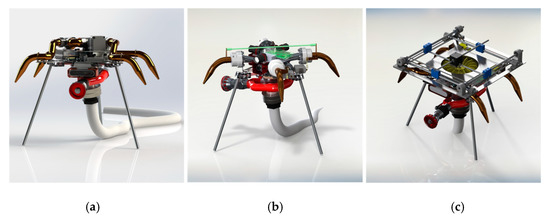
Figure 2.
The proposed designs. (a) Flow rate control system; (b) Nozzle rotation control system; (c) Weight distribution control system.
3.1. Flow Rate Control System
Three motorized valves are used to manipulate the amount of water going through each nozzle. Two of them distribute the water between two nozzles symmetrically about the head center, i.e., no. 1–3 nozzles and no. 2–4 nozzles. The other valve, i.e., the main valve, regulates the water flow between the two mentioned pairs. The yaw motion is achieved by operating this valve. The nozzles are fixed on the head part. The plane of the front nozzles is parallel to that of the rear, and the longitudinal motion of the head depends on its pitch orientation only. Water flutter phenomena may appear in this design, due to the sudden change of the flow from the opening/closing of the valves.
3.2. Nozzle Rotation Control System
Four nozzles connect to the main manifold by swivel joints so that they are rotatable. Servo motors are used to operate the nozzles’ rotations. In this way, the direction of the force generated by each nozzle can be changed. Nozzles no. 1 and 3 are linked together to achieve the minimal 3 actuators. The radially symmetrical arrangement of the nozzles avoids water jets from intersecting. However, this results in the input coupling in both horizontal motions.
3.3. Weight Distribution Control System
This design is inspired by the way a person leans his/her body to operate a jet board. In this system, a 2-degree linear motion mechanism is utilized on the horizontal plane of the head part. A weight block is shifted around by this mechanism resulting in a change in the total weight distribution of the head and the movement of the system. Moreover, it is shown in the mathematical model that the weight distribution control cannot operate the yaw rotation. Thus, a fan impeller is used, in which the drag moment of the fan rotates the head part, while it is arranged such that the air is blown upward, thus overcoming the drawbacks of the propeller-type firefighting system. However, this design may lead to complicated construction, weight increase, and non-minimum phase phenomenon due to the acceleration of the weight block.
4. System Modeling
4.1. Coordinate Systems and Kinematic Relationships
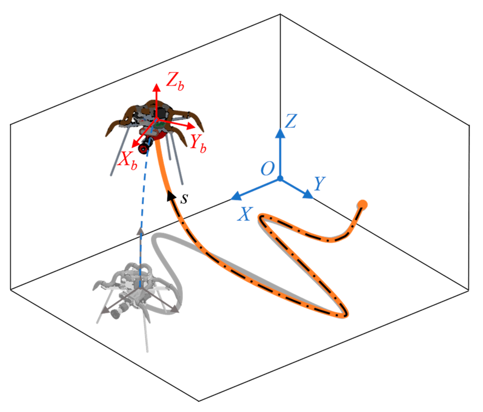
In order to analyze the motion characteristics of each design, mathematical models are formulated in this Section. For the sake of modeling, two Cartesian coordinates are defined and considered: the Earth reference and the head part fixed coordinates. A curvilinear coordinate is placed along the centerline of the water-conveying hose, with the beginning at the outlet of the pump and the ending at the head inlet. The coordinate systems are illustrated in Figure 3.
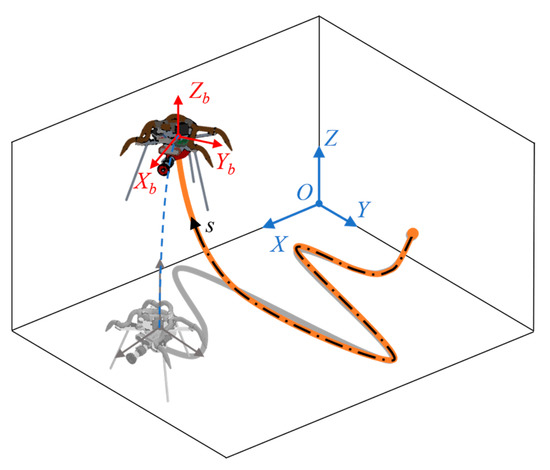
Figure 3.
Coordinate systems definition.
The kinematic relationship between two Cartesian coordinates is given by the following transformation matrix:
where the dot stands for the differential with respect to time (the time variable is neglected in the remaining for simplicity). Hence, and are the translational velocity vectors of the head in the reference frame and body frame, respectively. is the vector of Euler angle rates in XYZ rotation order, and is the vector of the corresponding angular velocities. and are the rotation matrices from the body frame to the reference frame and Euler angles, respectively. is the n-by-n zero matrix. For the sake of clarity, the subscript b in the remaining of the paper is for the body-fixed frame.
Subsequently, the velocity of the water flow at an inlet or outlet j, which is positioned by the vector in the body-fixed coordinate, namely , is given by:
where indicate the head inlet section, the outlet of the fire extinguishing nozzle, and the ith thrust nozzle’s outlet, respectively. is the axial velocity of the water flowing through the j section and is the normal vector of the section. The direction of follows the direction of the water flow going through the area. Especially, the normal vector of the head inlet, i.e., observed in the reference frame, is also the tangent vector of the water-conveying hose at this end. It is noted that the inlet port is designed such that it locates at the origin of the coordinate. Hence, is the relative velocity of the jetted water with respect to the head center. The cross-product term is the change in the water’s velocity due to the head rotation . Finally, is the head translation contributing to the absolute velocity of the water flow.
On the other hand, let define the location of the hose element at s curvilinear coordinate. The initial value of is denoted by . The hose has a uniform cross-sectional area so the water velocity at any point is equal to that at the head inlet, i.e., . Then, the hose and the fluid velocities are, respectively defined by:
where the prime stands for the differential with respect to s and is the tangent vector of the hose. At the end of the hose, i.e., , is the hose’s length, , and , Equations (2) and (3) are equivalent.
4.2. Water Conveying Hose Modeling
Either Newtonian, in the same manner as the head part in the next section, or Hamiltonian approaches can be adopted to establish the motion equations of the hose. Since the deformation of the hose in our system is significant, the latter method is more intuitive. The head part is first isolated from the hose and is replaced by a vector of reaction force. Then, the modified Hamilton principle for the assembly of the hose and the water inside is written as follows [33,34]:
where the right-hand terms associate with end effects due to the isolation of the head. is Hamilton’s variational operator. L is the Lagrangian including kinetic energy, bending strain energy, and gravitation. The formulations of the energies are given in the same manner in [33,34]. The term is the virtual works done by external forces, as follows:
The forces mentioned in Equation (5) include the reaction force from the head ; the interactive force with surroundings ; the force due to the pumping pressure at the hose inlet and exit pressure at the hose outlet ; the holding force due to the connection of the hose inlet to the pump outlet . Additionally, the Dirac delta function indicates the part of the hose where the force applies.
Substitute the Lagrangian and the kinematics in Equation (3) into Equation (4), and after a lengthy, but straightforward computation process, the governor equation of the hose conveying water is obtained as follows:
with the boundary conditions given by:
In which, and are the mass per unit length of the hose and the fluid, respectively. The flexural rigidity of the hose is denoted by EI. is the vector of the gravitational acceleration. Finally, and are the gauge pressure at the pump outlet and the head inlet, respectively.
Remark 1.
In onshore firefighting missions, contains the normal contact force with the ground and frictional force generated by the motion of the hose on the ground surface [35]. In offshore applications, includes the buoyancy force, hydrodynamic force, seabed interaction force, etc. [36].
Remark 2.
The three-dimensional translation can be reduced to two partial motions via the inextensible condition of the hose [33,34].
4.3. Head Part Modeling
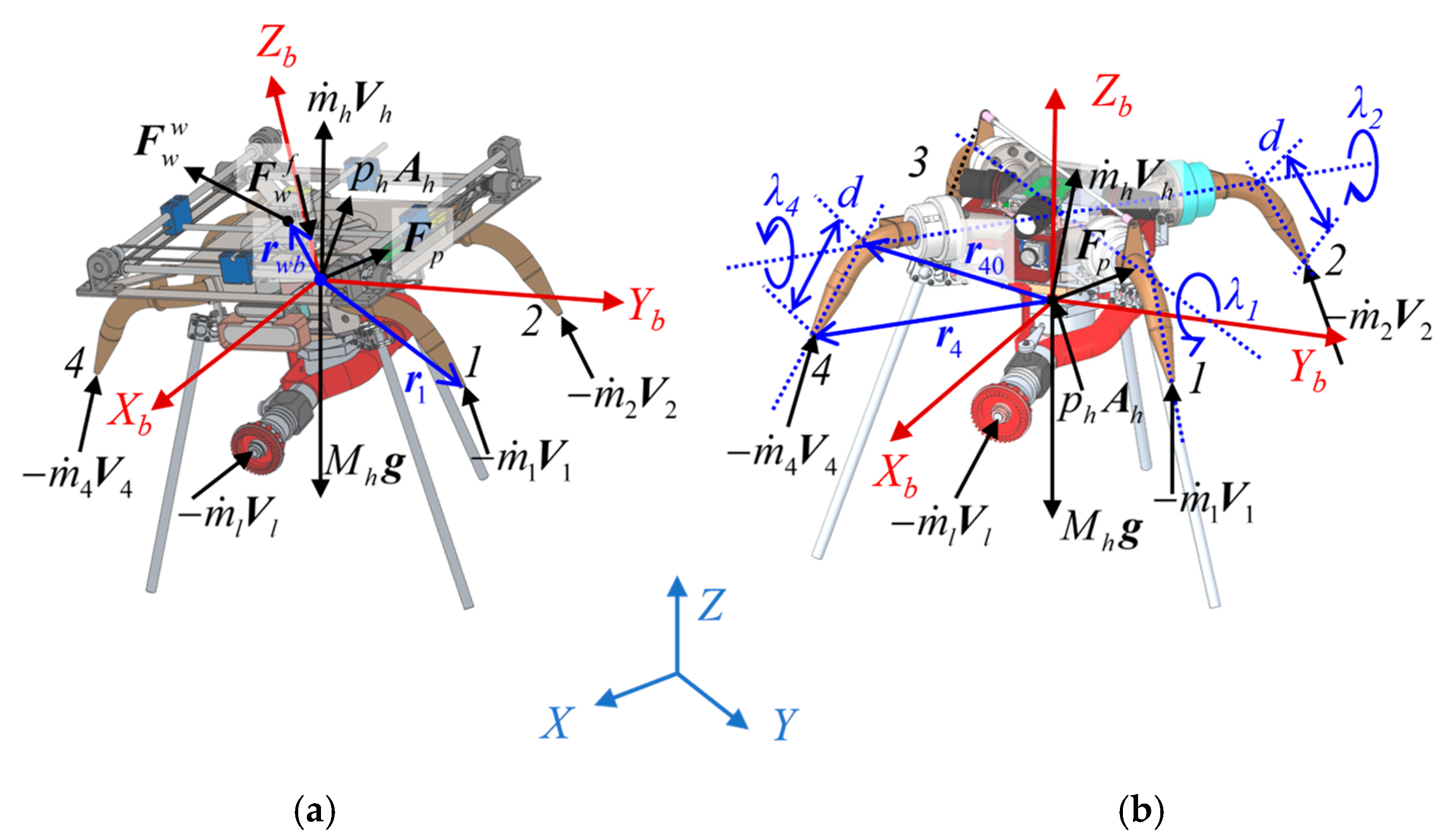
The head part can be considered as a rigid body by isolating the water hose, water flow, and weight block (in the third design) and replacing them with reaction forces and torques acting on the head. Figure 4 depicts the force allocation on the body-free diagram of the head.
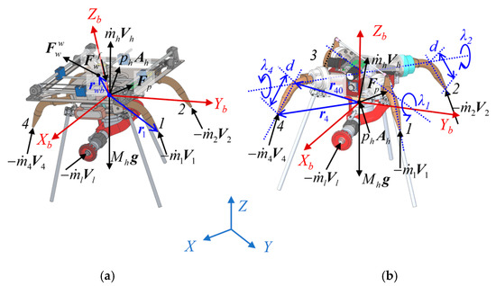
Figure 4.
Free body diagram of the head part: (a) The weight distribution control system; (b) The nozzle rotation control system.
The dynamics of the head part, represented in the body-fixed frame, are given in the following Newton-Euler formulations:
where is the mass of the head with its flowing through water, is the inertia tensor. and are the total force and torque acting on the head. With Assumptions (1)–(3), the forces and torques can be represented as in Equation (9).
Assumption 1.
The water volume contained in the head is considered undeforming and moving.
Assumption 2.
The water flow is steady. The remaining acceleration of the water will be treated as input disturbances.
Assumption 3.
External forces and torques due to wind, aerodynamic drag, and additional mechanisms are neglected in this stage of development.
is the mass flow rate flowing through the cross-sectional area . is the water density. The water conveyed by the hose is for both generating thrust and suppressing a flame.
The terms in brackets in Equation (9) are the force and torque generated by the change of the linear momentum of the water flowing through the head part. Considering the first two assumptions, the force and torque depend only on the momentum through the head inlet and the nozzles’ outlet. The water inlet of the head is located at the origin of the coordinate so that no torque is created by the input water.
On the other hand, is the gravitational acceleration observed from the body-fixed frame. represents the force acting at the water inlet area due to the gauge pressure at this area. The reaction force from the water conveying hose is denoted by , while the swivel ball joint, with the assumption of frictionless, isolates the reaction torque transmitting to the head. Finally, and are provided by the actuating mechanism in the third design, thus they are zeros in the first two designs.
By considering the boundary conditions (7) and the kinematics (1–3), the resulting equation of motion of the head part can be represented by:
with:
and the skew-symmetric matrix constructed from the corresponding vector .
4.4. Actuation Systems
The three proposed designs are different in their way to regulate the forces and torques acting on the head part.
4.4.1. Flow Rate Control System
The flow rate at the nozzles’ outlet can be represented through the control input as follows:
where maps the opening of a three-way valve to the resulting flow rates after it. is for the main valve, represents the valve that controls the flow rate between nozzles 1 and 3, and is for the flow rate between nozzles 2 and 4. is for the valve at its neutral position and the water flow distributed equally to the two outlets after it. indicates the valve is fully opened for the k-th nozzle(s) and fully closed for the opposite one; is the opposite.
4.4.2. Nozzle Rotation Control System
If the influence of the elevation difference and loss coefficients among the nozzles are neglected, then the flow rates jetted from the outlets are all equal. The changes in the direction of the nozzles result in the change of water velocity at the outlets, and the position vectors of the outlets, as follows:
In which, is the rotation of the i-th nozzle about the axis of the corresponding swivel joint, and is the matrix of this rotation. and are the normal vectors of the i-th outlet without and with the rotation since nozzles no.1 and 3 rotate together via the linkage between them. is defined as the position vector of the center of rotation of the i-th nozzle, and d is the distance from this point to the corresponding outlet.
4.4.3. Weight Distribution Control System
In the same manner as the previous system, the flow rates jetted from the outlets are all equal. Moreover, the nozzles do not rotate. The maneuverability of the system is controlled by the horizontal position of a weight block moving on its top, i.e., and . The reaction force and torque act on the head part due to the movement of the weight block are obtained from its motion dynamics as follows:
where:
is the mass of the block, and Jw and are the inertia tensor of the weight about the rotation center of the head and the mass center of the block, respectively. is the position vector of the weight block, in which the vertical distance is a constant value and horizontal positions and vary by the 2-degree linear motion mechanism.
Remark 3.
One can see the presence of the weight block’s acceleration, i.e., , in the motion equation of the head part. This acceleration introduces a non-minimum phase phenomenon to the system. That is, when the weight block moves to tilt the head part in one direction, the inertia force of the block makes the head initially moves backward before diving and moving in that same direction.
Remark 4.
A person can fully control his/her flyboard, especially the yaw rotation, by leaning back and forth, and side to side, thanks to the inextensible condition of the hose. However, with a long hose conveying water in the firefighting task, the weight distribution control approach is insufficient to control the yaw. Hence, an additional actuator is needed.
Now consider the use of an impeller fan, as in Figure 2c. Since its mass and inertia are small so being neglected. When the fan rotates, it generates thrust force and drag moment as follows [37]:
with the thrust coefficient, the drag coefficient, the air density, the fan disk area, the rotor radius, and the fan angular velocity.
Remark 5.
By substituting Equations (13), or (14), or (15), (16) and (17) into Equations (11) and (12), the motion equations of each design are completely obtained.
5. Motion Control System Design
An identical linear control scheme is designed and implemented for all of the proposed systems in order to evaluate their maneuverability. The objective of motion control is to pilot the firefighting systems to their working positions and maintain the stability of the systems while on duty. The working positions are represented by desired altitude, attitude, and horizontal positions. For this objective, we first linearize the system models. In the case of the water-conveying hose, the continuous partial differential equations are approximated with the finite difference method. Let , , , the difference operators [38] discretize and linearize Equation (6) to the following formulation:
or as in Equation (19).
In which, is the identity matrix of size n. From this state-space representation, one can see that for a given hose, its stability depends on the flow rate of the water flowing inside it. It is found that there is a critical flow rate, which is corresponding to a critical flow velocity, such that when the flow rate of the water is below it, the hose is stable. In contrast, when the water flow rate exceeds this critical value, flutter instability occurs. This conclusion is compatible with the dynamics of cantilevered pipes in [33,34].
On the other hand, if the hose is stable, is bounded. Then, by treating the influence of the hose on the head as disturbances, the motion equations of the head (11) with its actuation system (Equations (13), or (14), or (15)–(17)) can be linearized about the state variables, inputs, and outputs defined as follows:
where and define the local equilibrium point. is the desired altitude for the robot head and is the flow rate necessary to maintain the head at this height. The linear state-space of each system has the following standard form:
where matrices A and B are obtained by Lyapunov’s linearization method. C is the output matrix, and D is the vector of nonlinearities and disturbances. Additionally, a robust tracking and disturbance rejection control law is designed in the form:
In which, is the integration vector of tracking errors of the head’s horizontal positions, altitude, and attitude, respectively. and are the gain matrices, whose values are obtained using the linear matrix inequality method. Let us denote the following matrices, which are the system matrices of the servomechanism with the state vector :
with the vector of maximal values of control inputs. If there exist matrices and , and a constant such that the following inequalities hold:
the control gain matrices computed by:
guarantees the criteria of the system robustness and input saturations given as follows [39]:
The details of the system matrices and controllers’ gain matrices are given in Appendix A. One can see that the first matrix inequality in Equation (24) is the bounded-real lemma for the servomechanism with the system matrices in Equation (23). Meanwhile, the remainder in Equation (23) guarantees the constraints on the control input U.
6. Results and Discussion
In order to evaluate the maneuverability of each designed system, the above system models and control law are taken into comparative simulations. In particular, the numerical solution of the partial differential equation of the water hose can be rewritten as follows:
where the bending moment , according to the elementary beam theory, is . Additionally, is the spring stiffness, c is the damping coefficient, and is the vector of rotation. Hence, the approximation of a water hose contains a collection of rigid bodies with mass coupled with springs and dampers, as seen in the first and last lines of Equation (27). This is similar to the lumped parameter method for modeling a flexible body [40]. Moreover, each body element is also influenced by the water flow through it which is given by the second line of Equation (27). The system is assumed to operate in an onshore mission. That is, the interactive force includes the normal contact force with the ground and the frictional force generated by the motion of the hose on the ground surface. They are modeled as in [41]. The specifications of the designed systems and the parameters used in the simulation are listed in Table 1. It is also worth noting that the actuators have their own dynamics in actual systems. Simply put, there is a time required for the response of the actuators to reach the values given by the controller. In the simulation studies, we integrated their complete CAD models and implemented first-order filters to mimic these characteristics. We use MathWorks Simulink and Simscape Multibody to solve the models and conduct the simulation tests.

Table 1.
Specifications of the designed systems.
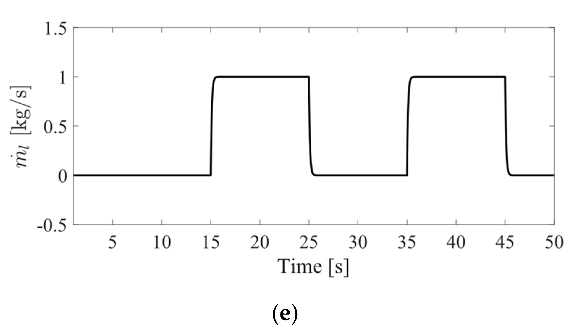
Two scenarios were considered, simply put, one with and one without the firefighting action. Three systems were initially land on the ground and take off and up the operating altitude at 03 [m]. The beginning of the hose is simply fixed in the simulations. The systems then perform positioning at the desired set points on the horizontal plane. At the same time, the heading angles of the head parts vary following a sinusoidal trajectory. These motions mimic the maneuver that a firefighting system has to perform while on duty, including approaching several fire sites and spaying the water widely to cover the fires. Figure 5 and Supplementary Video S1 show the motions of the three considered systems without the firefighting action. This simulation is to validate the maneuverability of these designs. On the other hand, Figure 6 and Supplementary Video S2 present the results in the other scenario, i.e., with the firefighting action. The action is represented by an additional water flow of water through the fire extinguishing nozzle at a flow rate of 01 [kg/s], lasting 10 [s] every 10 [s] interval. This flow is depicted in Figure 6e.
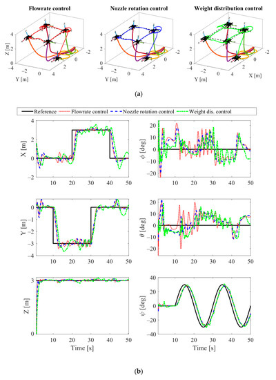
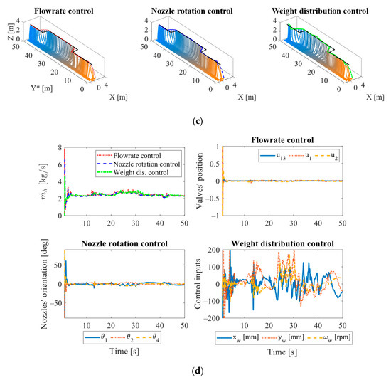
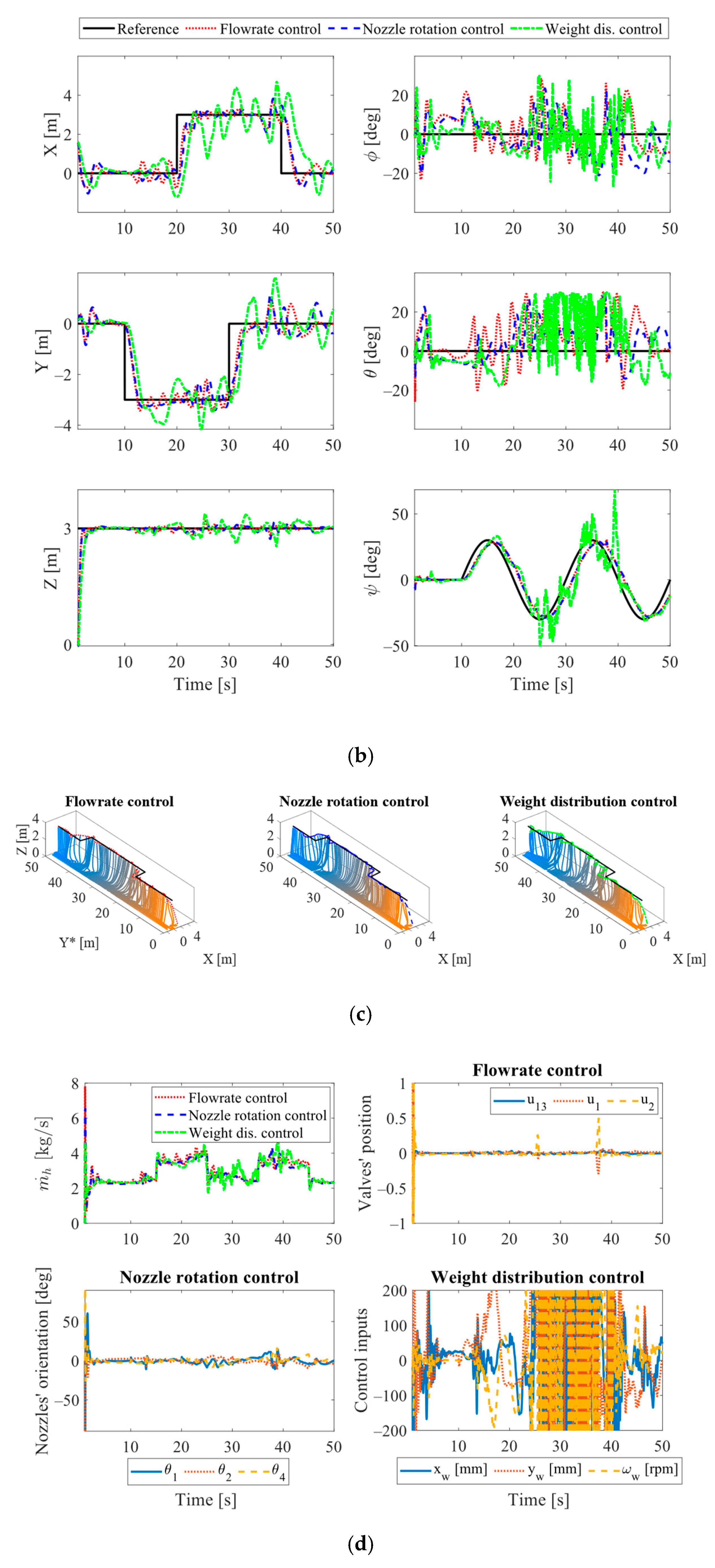
Figure 5.
Motion performance of the proposed designs. (a) Tracking performance in three-dimensional geometry; (b) Time responses of translations and rotations; (c) three-dimensional partial motion of the water-conveying hose; (d) Control inputs.
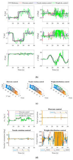
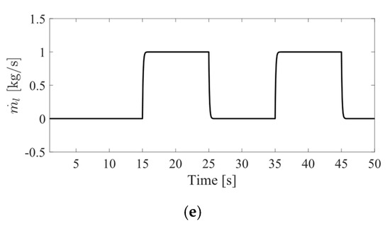
Figure 6.
Performance of the proposed designs in a firefighting mission. (a) Tracking performance in three-dimensional geometry; (b) Time responses of translations and rotations; (c) three-dimensional partial motion of the water-conveying hose; (d) Control inputs; (e) Fire extinguishing nozzle’s flow rate.
In the first scenario, all of the systems’ heads are able to follow the required references. The tracking performances in Figure 5a and the time responses in each direction in Figure 5b indicate that the flow rate control and nozzle rotation control systems perform significantly better than the weight distribution control approach. The two systems quickly reach the desired altitude and properly track their motion references most of the time. Meanwhile, the responses and control inputs (Figure 5d) of the weight distribution control system indicate that it struggles to perform in every direction. The inertia force due to the movement of the actuating weight affects the outputs of the system. Figure 5d also validates that the control inputs of all systems are within their respective saturations. On the other hand, the roll and pitch rotations of the heads should be ideally maintained at zeros. However, these rotations are coupled with horizontal motions. Their values vary with time in order to either move the system heads or compensate for the disturbances acting on the systems. Their values in Figure 5b are kept nearby zero and prevent the systems from flipping over.
Figure 5a,b and Supplementary Video S1 also show that the effects of the dynamics of the water hoses on the motions of the heads are noteworthy. In particular, the tension of the hoses leads to large overshoots in horizontal motions when the systems take off. The tension also results in the fluctuations between the 20th [s] and 30th [s] when the systems’ heads reach their furthest positions. Moreover, the postures of the water hoses are plotted for every second in Figure 5c. The Y* axis represents the Y-coordinate being spread out with time. One can see that the water hose of the latest system fluctuates the most. This contributes to the worst performance of this system. The hose in the flow rate control design swings less than this, but more than the hose in the nozzle rotation control system. The flow rate control system, as its name, regulates the flow rates of the nozzle to maneuver, thus causing the flow to flutter inside the hose. This phenomenon can be seen in Figure 5d and results in the hose movement. Then, more disturbances act on the motion of the system head. That explains why its roll and pitch rotations oscillate more than those of the nozzle rotation control system.
Similar comparative conclusions are drawn in the second scenario. The first two designs provide adequate performance while the latest design performs worst. The nozzle rotation control system remains the better one. The influence of the firefighting action and the robustness of the control system are also revealed, as shown in Figure 6 and Supplementary Video S2. Whenever a fire extinguishing nozzle changes its operating status, the corresponding system initially deviates from its current position due to the reaction force from this nozzle. The control inputs then quickly compensate it and bring the head to the desired reference. However, the impact of disturbances on motion performances is still considerable. The designed control law can preserve the systems’ stability, but cannot effectively reject the disturbances acting on the system.
7. Conclusions
Three designs of water-powered aerial systems with different actuators have been proposed and analyzed in this paper, namely the flow rate control system, nozzle rotation control system, and weight distribution control system. The systems have potential in the firefighting missions performed in water areas and can extend to every fire site with sufficient water availability. In this study, the dynamical characteristics of the three systems have been formulated. A linear control scheme has been designed and implemented for them. In the end, the comparative simulations indicate that both the flow rate control system and nozzle rotation control system provide adequate motion performance. For these two systems, the designed control law preserves the systems’ stability and guarantees the input saturations. The nozzle rotation control system is the better one, with greater tracking results of the head and smaller fluctuations of the water hose. Therefore, this design is chosen to be developed further.
However, the designed control law cannot deal with perturbations effectively. The linear controller is designed based on the linearization of the system about a local equilibrium point, such that nonlinearities and other effects are neglected. For the chosen actuator method, more advanced control techniques will be considered where the motion of the hose will be incorporated into the control law. At the same time, prototypes of the nozzle rotation control system will be fabricated, and experimental studies will be conducted for evaluation.
Supplementary Materials
The following supporting information can be downloaded at: https://www.mdpi.com/article/10.3390/app13031965/s1, Video S1: Supplementary Video S1, Video S2: Supplementary Video S2.
Author Contributions
Conceptualization, T.H. and Y.-B.K.; methodology, T.H.; software, Y.-B.K.; validation, T.H., D.-H.L., and Y.-B.K.; investigation, T.H. and Y.-B.K.; writing—original draft preparation, T.H.; writing—review and editing, T.H., D.-H.L., and Y.-B.K.; visualization, T.H.; supervision, Y.-B.K.; project administration, Y.-B.K.; funding acquisition, Y.-B.K. All authors have read and agreed to the published version of the manuscript.
Funding
This work was supported by the National Research Foundation of Korea (NRF) grant funded by the Korean government (MSIT) (No. 2022R1A2C1003486).
Institutional Review Board Statement
Not applicable.
Informed Consent Statement
Not applicable.
Data Availability Statement
Not applicable.
Acknowledgments
This work was also supported by the National Research Foundation (NRF), South Korea, under Project BK21 FOUR (Smart Convergence and Application Education Research Center).
Conflicts of Interest
The authors declare no conflict of interest.
Appendix A
Details of the linear state-space of each system given in Equation (21), and the control matrices obtained by Equations (24) and (25), are as follows:
- For the flow rate control system:
- For the nozzle rotation control system:
- For the weight distribution control system:
References
- Shark Robots—Shark Robotics. Available online: https://www.shark-robotics.com/robots (accessed on 21 September 2022).
- Thermite—Howe & Howe Technologies. Available online: https://www.howeandhowe.com/civil/thermite (accessed on 21 September 2022).
- TEC800 Firefighting Robot—Angatec. Available online: https://www.angatec.com/en/tec800/ (accessed on 21 September 2022).
- Zhang, J.; Jin, Z.; Feng, H. Type synthesis of a 3-mixed-DOF protectable leg mechanism of a firefighting multi-legged robot based on GF set theory. Mech. Mach. Theory 2018, 130, 567–584. [Google Scholar] [CrossRef]
- Zhang, J.; Jin, Z.; Zhao, Y. Dynamics analysis of leg mechanism of six-legged firefighting robot. J. Mech. Sci. Technol. 2018, 32, 351–361. [Google Scholar] [CrossRef]
- Liljeback, P.; Stavdahl, O.; Beitnes, A. SnakeFighter—Development of a Water Hydraulic Fire Fighting Snake Robot. In Proceedings of the 2006 9th International Conference on Control, Automation, Robotics and Vision, Singapore, 5–8 December 2006; pp. 1–6. [Google Scholar]
- Lahr, D.; Orekhov, V.; Lee, B.; Hong, D. Early Developments of a Parallelly Actuated Humanoid, SAFFiR. In Proceedings of the 37th Mechanisms and Robotics Conference, Portland, OR, USA, 4–7 August 2013; Volume 6B. [Google Scholar]
- Kim, J.-H.; Jo, S.; Lattimer, B.Y. Feature Selection for Intelligent Firefighting Robot Classification of Fire, Smoke, and Thermal Reflections Using Thermal Infrared Images. J. Sens. 2016, 2016, 8410731. [Google Scholar] [CrossRef]
- Jeyavel, J.; Prasad, A.A.; Shelke, K.M.; Sargade, P.D.; Thoke, U.V. Survey on Fire Fighting techniques using Unmanned Aerial Vehicles. In Proceedings of the 2021 International Conference on Advance Computing and Innovative Technologies in Engineering (ICACITE), Greater Noida, India, 4–5 March 2021; pp. 239–241. [Google Scholar]
- Harikumar, K.; Senthilnath, J.; Sundaram, S. Multi-UAV Oxyrrhis Marina-Inspired Search and Dynamic Formation Control for Forest Firefighting. IEEE Trans. Autom. Sci. Eng. 2019, 16, 863–873. [Google Scholar] [CrossRef]
- Qin, H.; Cui, J.Q.; Li, J.; Bi, Y.; Lan, M.; Shan, M.; Liu, W.; Wang, K.; Lin, F.; Zhang, Y.F.; et al. Design and implementation of an unmanned aerial vehicle for autonomous firefighting missions. In Proceedings of the 2016 12th IEEE International Conference on Control and Automation (ICCA), Kathmandu, Nepal, 1–3 June 2016; pp. 62–67. [Google Scholar]
- Chaikalis, D.; Tzes, A.; Khorrami, F. Aerial Worker for Skyscraper Fire Fighting using a Water-Jetpack Inspired Approach. In Proceedings of the 2020 International Conference on Unmanned Aircraft Systems (ICUAS), Athens, Greece, 1–4 September 2020; pp. 1392–1397. [Google Scholar]
- Spurny, V.; Pritzl, V.; Walter, V.; Petrlik, M.; Baca, T.; Stepan, P.; Zaitlik, D.; Saska, M. Autonomous Firefighting Inside Buildings by an Unmanned Aerial Vehicle. IEEE Access 2021, 9, 15872–15890. [Google Scholar] [CrossRef]
- Ehang|Smart City Management—Ehang 216F. Available online: https://www.ehang.com/ehang216f/ (accessed on 21 September 2022).
- Zhun—Walkera. Available online: https://www.walkera.com/index.php/Goods/info/id/71 (accessed on 21 September 2022).
- Drone Could Help Firefighters by Putting Out Fires. Available online: https://www.youtube.com/watch?v=Bm2BVTTir4c (accessed on 21 September 2022).
- High-Rise Firefighting with Dry Powder Fire Extinguishing—Guofei UAV. Available online: http://www.guofei-uav.com/index.php?c=article&a=type&tid=43 (accessed on 21 September 2022).
- Zapata, F. Maneuvering and Stability Control System for Jet-Pack. U.S. Patent US20140103165A1, 17 April 2014. [Google Scholar]
- Li, R. Personal Propulsion Device. U.S. Patent US7735772B2, 21 August 2007. [Google Scholar]
- Robinson, B. Water Propelled Flying Board. U.S. Patent US9145206B1, 29 September 2015. [Google Scholar]
- Jetovator—Rise the Hose. Available online: https://www.jetovator.com/ (accessed on 21 September 2022).
- Water—Zapata. Available online: https://www.zapata.com/en/water/ (accessed on 21 September 2022).
- Dubai Media Office. Available online: https://twitter.com/DXBMediaOffice/status/822797935176024065 (accessed on 21 September 2022).
- Dubai Firefighters Use Jetpacks to Aid High-Speed Response—Euronews. Available online: https://www.youtube.com/watch?v=H1VIxUTzb1I (accessed on 21 September 2022).
- Liu, X.; Zhou, H. Unmanned Water-Powered Aerial Vehicles: Theory and Experiments. IEEE Access 2019, 7, 15349–15356. [Google Scholar] [CrossRef]
- Ando, H.; Ambe, Y.; Ishii, A.; Konyo, M.; Tadakuma, K.; Maruyama, S.; Tadokoro, S. Aerial Hose Type Robot by Water Jet for Fire Fighting. IEEE Robot. Autom. Lett. 2018, 3, 1128–1135. [Google Scholar] [CrossRef]
- Yamaguchi, T.; Ambe, Y.; Ando, H.; Konyo, M.; Tadakuma, K.; Maruyama, S.; Tadokoro, S. A Mechanical Approach to Suppress the Oscillation of a Long Continuum Robot Flying with Water Jets. IEEE Robot. Autom. Lett. 2019, 4, 4346–4353. [Google Scholar] [CrossRef]
- Yamauchi, Y.; Ambe, Y.; Konyo, M.; Tadakuma, K.; Tadokoro, S. Passive Orientation Control of Nozzle Unit with Multiple Water Jets to Expand the Net Force Direction Range for Aerial Hose-Type Robots. IEEE Robot. Autom. Lett. 2021, 6, 5634–5641. [Google Scholar] [CrossRef]
- Yamauchi, Y.; Ambe, Y.; Konyo, M.; Tadakuma, K.; Tadokoro, S. Realizing Large Shape Deformations of a Flying Continuum Robot with a Passive Rotating Nozzle Unit That Enlarges Jet Directions in Three-Dimensional Space. IEEE Access 2022, 10, 37646–37657. [Google Scholar] [CrossRef]
- Ambe, Y.; Yamauchi, Y.; Konyo, M.; Tadakuma, K.; Tadokoro, S. Stabilized Controller for Jet Actuated Cantilevered Pipe Using Damping Effect of an Internal Flowing Fluid. IEEE Access 2022, 10, 5238–5249. [Google Scholar] [CrossRef]
- Lee, D.-H.; Huynh, T.; Kim, Y.-B.; Soumayya, C. Motion Control System Design for a Flying-Type Firefighting System with Water Jet Actuators. Actuators 2021, 10, 275. [Google Scholar] [CrossRef]
- Dinh, C.-T.; Huynh, T.; Kim, Y.-B. LQI Control System Design with GA Approach for Flying-Type Firefighting Robot Using Waterpower and Weight-Shifting Mechanism. Appl. Sci. 2022, 12, 9334. [Google Scholar] [CrossRef]
- Paidoussis, M.P. Fluid-Structure Interactions: Slender Structures and Axial Flow; Academic Press: Cambridge, MA, USA, 1998; Volume 1, ISBN 008053175X. [Google Scholar]
- Chen, W.; Dai, H.; Wang, L. Three-dimensional dynamical model for cantilevered pipes conveying fluid under large deformation. J. Fluids Struct. 2021, 105, 103329. [Google Scholar] [CrossRef]
- MathWorks Spatial Contact Force—Multibody Modeling. Available online: https://www.mathworks.com/help/physmod/sm/ref/spatialcontactforce.html (accessed on 27 August 2022).
- Liang, M.; Xu, S.; Wang, X.; Ding, A. Simplification of mooring line number for model testing based on equivalent of vessel/mooring coupled dynamics. J. Mar. Sci. Technol. 2020, 25, 573–588. [Google Scholar] [CrossRef]
- Bouabdallah, S.; Siegwart, R. Full control of a quadrotor. In Proceedings of the 2007 IEEE/RSJ International Conference on Intelligent Robots and Systems, San Diego, CA, USA, 29 October–2 November 2007; pp. 153–158. [Google Scholar]
- Leader, J.J. Numerical Analysis and Scientific Computation; CRC Press: Boca Raton, FL, USA, 2022; ISBN 1000540391. [Google Scholar]
- Boyd, S.; El Ghaoui, L.; Feron, E.; Balakrishnan, V. Linear Matrix Inequalities in System and Control Theory; Society for Industrial and Applied Mathematics: Philadelphia, PA, USA, 1994; ISBN 978-0-89871-485-2. [Google Scholar]
- Miller, S.; Soares, T.; Van Weddingen, Y.; Wendlandt, J. Modeling Flexible Bodies with Simscape Multibody Software. An Overview of Two Methods for Capturing the Effects of Small Elastic Deformations; Technical Paper; MathWorks: Natick, MA, USA, 2017. [Google Scholar]
- Modeling Contact Force between Two Solids—MATLAB & Simulink. Available online: https://www.mathworks.com/help/releases/R2021b/physmod/sm/ug/modeling-contact-force-between-two-solids.html (accessed on 21 September 2022).


Disclaimer/Publisher’s Note: The statements, opinions and data contained in all publications are solely those of the individual author(s) and contributor(s) and not of MDPI and/or the editor(s). MDPI and/or the editor(s) disclaim responsibility for any injury to people or property resulting from any ideas, methods, instructions or products referred to in the content. |
© 2023 by the authors. Licensee MDPI, Basel, Switzerland. This article is an open access article distributed under the terms and conditions of the Creative Commons Attribution (CC BY) license (https://creativecommons.org/licenses/by/4.0/).