Article

A 3D Model Applied to Analyze the Mechanical Characteristic of Living Stump Slope with Different Tap Root Lengths

1
School of Civil and Engineering Management, Guangzhou Maritime University, Guangzhou 501725, China
2
School of Civil Engineering, Central South University of Forestry and Technology, Changsha 410004, China
3
Engineering Research Center of Catastrophic Prophylaxis and Treatment of Road & Traffic Safety of Ministry of Education, Changsha University of Science & Technology, Changsha 410114, China
4
School of Civil Engineering, Chongqing Jiaotong University, Chongqing 400074, China
*
Author to whom correspondence should be addressed.
Appl. Sci. 2023, 13(3), 1978; https://doi.org/10.3390/app13031978
Submission received: 16 December 2022 / Revised: 29 January 2023 / Accepted: 31 January 2023 / Published: 3 February 2023
(This article belongs to the Special Issue Sustainable Agriculture and Soil Conservation II)

Abstract

:
Although the current ecological engineering technology can reinforce shallow landslides, it cannot reinforce deep landslides. A new type of ecological engineering technology-living tree stump slope protection was developed, aiming at the deficiency of current ecological engineering technology. For living stumps with different tap root lengths, the mechanical properties of the living stump slope and root system were analyzed. The model was based on the finite element method, using the Mohr-Coulomb failure criterion to consider the mechanical plasticity of the soil. The three-dimensional (3D) models of living stumps with different tap root lengths were simulated by embedded beam elements. Changes in stress and strain of soil and root system were simulated. The strength reduction method was used here to calculate the safety factor of the slope. The results showed that long taproots moved the soil shear stress area to deeper soil layers, increasing the stability of the slope. The root system in the middle and lower part of the slope mainly exerted its tensile strength and played a positive role in the stability of the slope. The longer the taproots, the more stable the slope. Slope stability may be affected by root length, spatial root morphology, and the spatial layout of the root system on the slope. Planting living stumps in the middle and lower part of the slope densely was recommended in ecological engineering.

1. Introduction

Plant roots have the functions of shallow root reinforcement and deep root anchoring [1,2,3,4], and they can effectively improve the stability of the slope [5]. The current ecological engineering technology mainly uses herbs, shrubs, or herbs combined with engineering protection, which can effectively reduce the occurrence of shallow landslides [6,7,8]. For example, vetiver grass can effectively prevent shallow landslides and improve slope stability [9,10,11]. As far as all the current ecological engineering protection technologies are concerned, although they have a good reinforcement effect on shallow landslides, they cannot reinforce deep landslides. Slope stabilization with living stumps is a new form of ecological engineering [12,13], which is to plant or drive living stumps with strong vitality into the soil. After a period of time, the living stumps will grow strong root systems, as shown in Figure 1. The root system of the living stump crosses the potential sliding surface of the slope; therefore, it plays a role in strengthening and protecting the slope.
The enhancement of the slope stability by the root system is mainly achieved by the following two methods. (1) Treat the root system as a bar similar to soil nails and add it to the soil for analysis. (2) The rooted soil is regarded as a root-soil complex, and an equivalent reinforcement layer is used to replace the rooted soil layer for analysis. In the current slope stability analysis, 2D models are widely used in numerical simulations [14,15]. Hubble et al. proposed a simple 2D model to estimate the stability of vegetated riverbanks, in which three root-reinforced zones in the upper soil layer of the slope were suggested [16]. Ji et al. investigated the effect of the spatial layout of root reinforcement and slope geometry on slope stability using 2D finite element analysis [17]. The research showed that compared with other locations, the vegetation at the bottom one-third part of the slope had a greater influence on the stability of the slopes. In the middle of the slope, the tap or heart root systems would have sufficient depth to interact with the sliding surface and provide better shearing resistance in soils [18]. In [19,20,21] authors applied 2D finite element analysis to study the influence of plant roots on slope stability. H. Zhu et al. analyzed the influence of factors such as root diameter, root length, and root position on slope stability through 2D finite element analysis [22]. However, studies on the influence of plant roots on slope stability, which considered the roots as rod-shaped units or simplified the root-soil complex into homogeneous materials, failed to consider the 3D spatial layout of plant roots. Few scholars considered the 3D characteristics of the root system in slope stability. Li et al. summarized the root-soil complex as soils with different cohesion in a 3D model and studied the influence of the spatial layout of root structure on slope stability [23]. Danjon et al. obtained accurate root structure data from mature oak trees by using 3D in-situ digitization and conducted stability analysis [24]. They concluded that the uniform arrangement of trees had little effect on fixing the soil. The staggered arrangement of trees will improve slope stability. Fan & Lai established a 3D simplified root model (one tap root and four lateral roots) to study the influence of the spatial layout of vegetation on slope stability [25]. In [26] authorsused embedded beam elements to simulate the root system and explored the anchoring mechanism of tree roots under the wind. Y. Zhu et al. (from the same research group) established a 3D simplified living stump root system, supported the slope together with bamboo anchors, and analyzed the stability of the slope [27]. It showed that living stumps with developed root systems had a good effect on preventing deep landslides. Nevertheless, most of the above research has not taken the influence of the three-dimensional root system on the mechanical properties of the slope and the stress on the root structure.
In this paper, we used numerical simulations to analyze the effect of living stumps with different tap root lengths on slope stability. The safety factor of the slope was calculated under three different conditions. Mechanical properties of slopes and roots of living stumps were analyzed through numerical simulation. This may provide reliable theoretical support for exploring the reinforcement mechanism of live stump slopes and the application of live stump slope protection technology.

2. Materials and Methods

2.1. Selection of Living Stump Tree Species

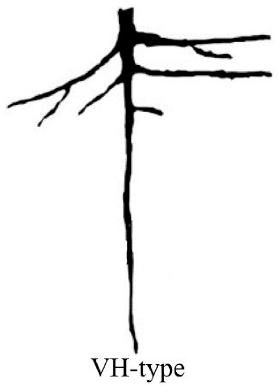
It can be seen from Figure 1 that when the tap root of the living stump is deep enough to penetrate the sliding surface of the slope and enter the deep soil layer, the tap root can better play its anti-shearing role. When the horizontal lateral root is well developed and longer, it can better exert the horizontal anchoring effect. If the root system has the characteristics of deep-rooted, well-developed, and long horizontal lateral roots, the stability of the plant slope can be better guaranteed. Kokutse et al. fully proved this point by analyzing the influence of tap roots, heart roots, and plate roots on slope stability [28]. It was concluded that tap roots could reinforce slopes against landslides more effectively than heart roots and plate roots in reinforcing slopes. A n elm tree with well-developed roots was selected as the research object to make the living stump support structure have a better slope reinforcement effect. The root system of elm is VH type [29]. There are a large number of horizontal roots in the root system, and the tap roots are long and deeply buried. Figure 2 shows the patterns of elm root architecture.

2.2. Root System Model of Living Stump

Due to the complexity of the root structure of 3D solid element mesh, the roots were considered embedded beam elements [30]. All roots are structures embedded in and integrated with the soil. The embedded element method does not consider the stress transmission at the interface and makes assumptions about the translational motions of the embedded root elements. Its simplified considerations enable this method to solve certain problems of complex geometries.
For the convenience of analysis and discussion, some assumptions were made: (1) It is assumed that the root system of living elm tree stumps will grow as expected after being planted in the soil, with a vertical and deep tap root and well-developed lateral roots. (2) The root system model does not consider roots with smaller diameters, such as fibrous roots and heart roots (roots with smaller diameters have less anchoring effect on soil) [31]. (3) The force and deformation of all roots are within the elastic range (regardless of the shape deformation of the root system, assuming that the Es of the root system remains unchanged). (4) The cross-sections of all roots are circular. According to the research of [32], the root diameter of 4–6 years old elms is mostly 10–15 cm, and that of 10–15 years old elms is mostly 15–20 cm. The tap roots of the elm trees branch out into lateral roots at a shallower depth, with many developed lateral roots [33]. Combined with the growth law of elm trees (as mentioned above), a simplified root system model with 1 tap root and 6 lateral roots was established by using embedded beam elements, and each root system was divided into 20 units. Six lateral roots branch at a distance of 25 cm from the top of the tap root, the included angle between each lateral root is 60°. The angle between the lateral root and the horizontal direction is about 20° (Figure 3). Both the tap roots and the lateral roots are simulated by variable cross-section groups (the diameter and length are linear). To simulate the growth of real elm trees, the diameter and length of the lateral roots will increase with the increase of the length of the tap root, as shown in Figure 4.

2.3. Root Systems and Soil Parameters

The root material parameters refer to the actual root parameters measured by [34,35] (Table 1). The soil material was assumed to be initially linear elastic (defined by elastic modulus Es) and combined with the plastic behavior modeled by the Mohr-Coulomb failure criterion available in the Midas GTS/NX materials library (Table 2).

2.4. Living Stump Slope Model

2.4.1. Strength Reduction FEM

Strength reduction FEM is to judge the deformation of the slope and the change of plastic zone by reducing the shear strength of soil and determining the strength safety factor. The safety factor of the slope is derived from the following formula [36]:
c = c k   ,   c = arctan ( tan ρ K )
where c and ρ are the original cohesion and internal friction angle of the slope, K is the reduction factor, c and ρ are the reduced cohesion and internal friction angle. When the strength reduction method is used for numerical analysis, the initial reduction coefficient is first selected, and the reduced soil strength parameters are input into the FEM for calculation. If the result is convergent, it means that the soil is still in a stable state, which continues to increase the coefficient until the calculated result does not converge. The strength reduction factor is the slope stability safety factor K at this time, and the sliding surface is the actual failure sliding surface of the slope.

2.4.2. Simulation Set-Up

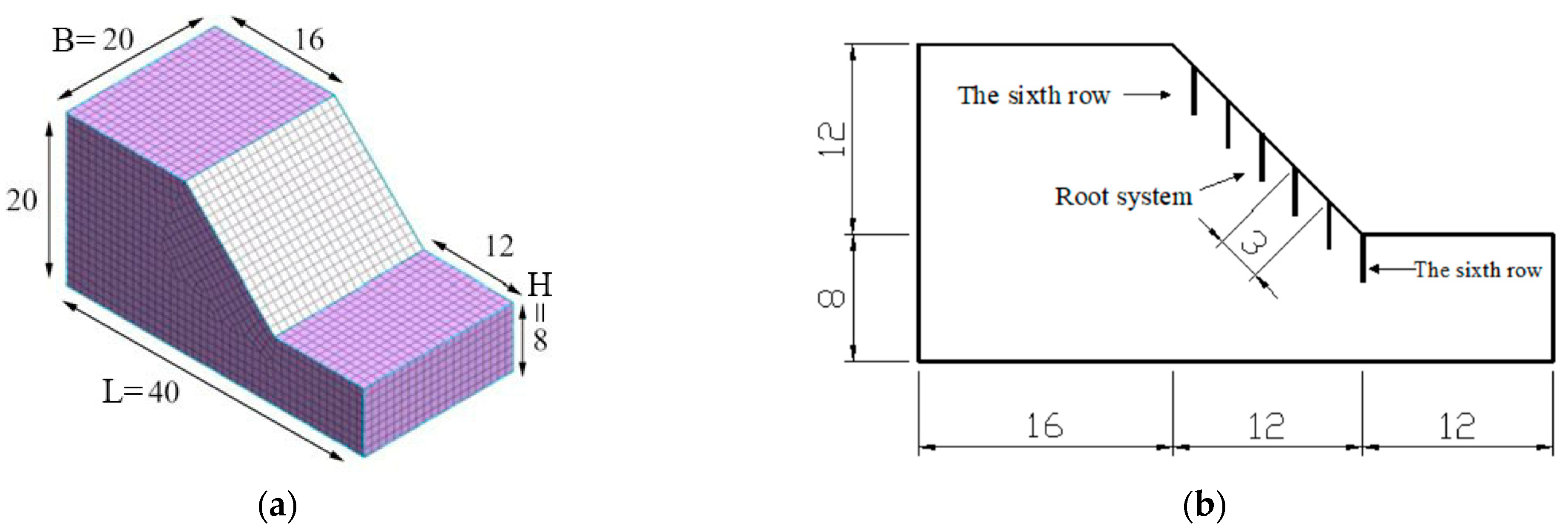
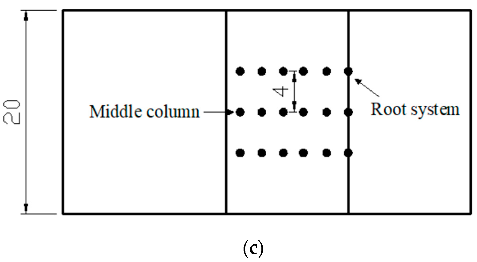
In this paper, the finite element software Midas GTS/NX was selected for numerical analysis. The soil mesh was generated by hybrid mesh survivors. The restraint was fixed, which fixes the lateral displacement in four directions and the displacement at the bottom of the model. The slope model was based on the National Natural Science Foundation of China (Nos.31971727). The slope height is H = 8 m, the slope width is B = 20 m, the slope ratio is 1:1, the distance between the foot of the slope and the right edge is 1.5 H = 12 m, the distance between the top of the slope and the left edge is 16 m, and the total height of the upper and lower boundaries is 20 m. The bottom of the model is L = 40 m, and the gravity field was applied with the gravity constant g = 9.81 m/s2.
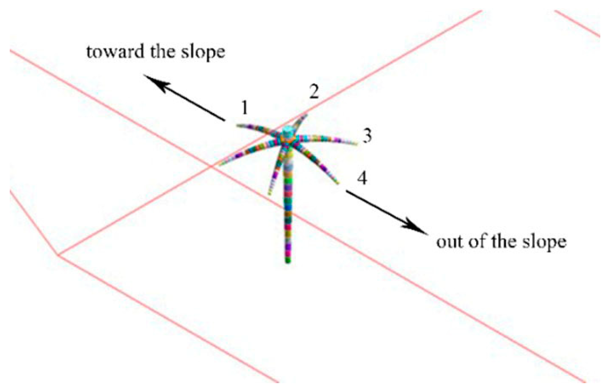
Six rows of root systems were arranged on the slope, and 3 root systems were arranged in each row. There are one to six rows from the foot of the slope to the top of the slope, in which the foot of the slope is the first row, and the top of the slope is the sixth row. The tap root spacing is 4 m, and the row spacing is 3 m. The slope model and root system layout figure are shown in Figure 5. Since the lateral roots of the elm trees are relatively developed, the lateral root units penetrating the slope are deleted to simulate the real growth of the root system. Figure 6 shows the root label of the toe of the slope.

3. Results

3.1. Potential Sliding Surface and Safety Factors of Living Stump Slope

The safety factors under different conditions calculated by the strength reduction method are shown in Table 3. Compared with the bare slope, the safety factor of the living stump slope supported by the 2 m, 3 m, and 4 m long tap root system is increased by 11.87%, 30.78%, and 40.85%, respectively, as shown in Table 3. The failure of the slope is mainly a shear failure, and the judgment of the penetration of the plastic zone is mainly based on the shear strain. The equivalent plastic strain in the three-dimensional slope model can show the most dangerous sliding surface of the slope. The potential sliding surfaces of the slopes under different conditions are shown in Figure 7. The red area in the figure is the area with a large plastic strain, that is, the potential sliding surface of the slope. The sliding surface depth was measured by Midas. It can be seen from the figure that the potential sliding surface depth of the bare slope is about 2.36 m, and the toe of the slope is most likely to be damaged. The potential sliding surface depth of the slope with 2 m tap roots is 3.01 m, the depth of the slope with 3 m tap roots is 3.44 m, and when the tap roots grew to 4 m, the deepest sliding surface of the slope is 4.57 m.

3.2. Roots Mechanical Characteristics

3.2.1. Tap Roots Stress Characteristics

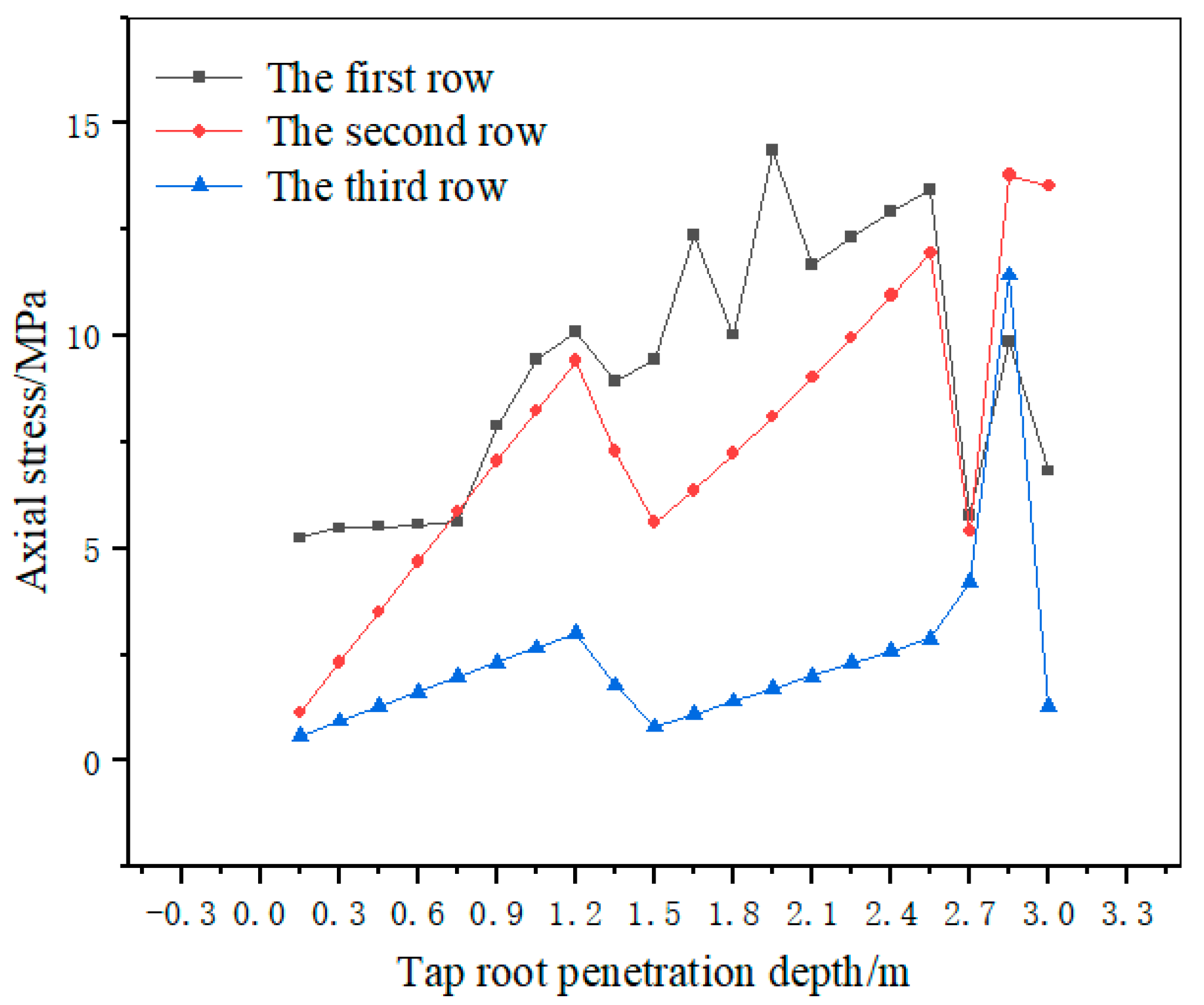
Investigated the 3 m tap roots in the middle row, the second and third rows are mainly under tensile stress (Figure 8), and the farther the tap roots are from the slope toe, the smaller the tensile stress is. The tap root of the slope toe shows a trend of increasing first and then decreasing. The maximum tensile stress generates at a depth of 1.95 m. The tensile stress trend of the second row of the tap root was basically the same as that of the tap root at the slope toe, and the maximum tensile stress was generated at a depth of 2.85 m. Figure 9 shows the fourth to sixth rows of tap root stress. The fourth to sixth rows of tap roots were mainly under compressive stress. They were subjected to small compressive stress at 0–1.2 m, and then, the root of the fifth-row tap produced the maximum compressive stress at the end.

3.2.2. Lateral Roots Stress Characteristics

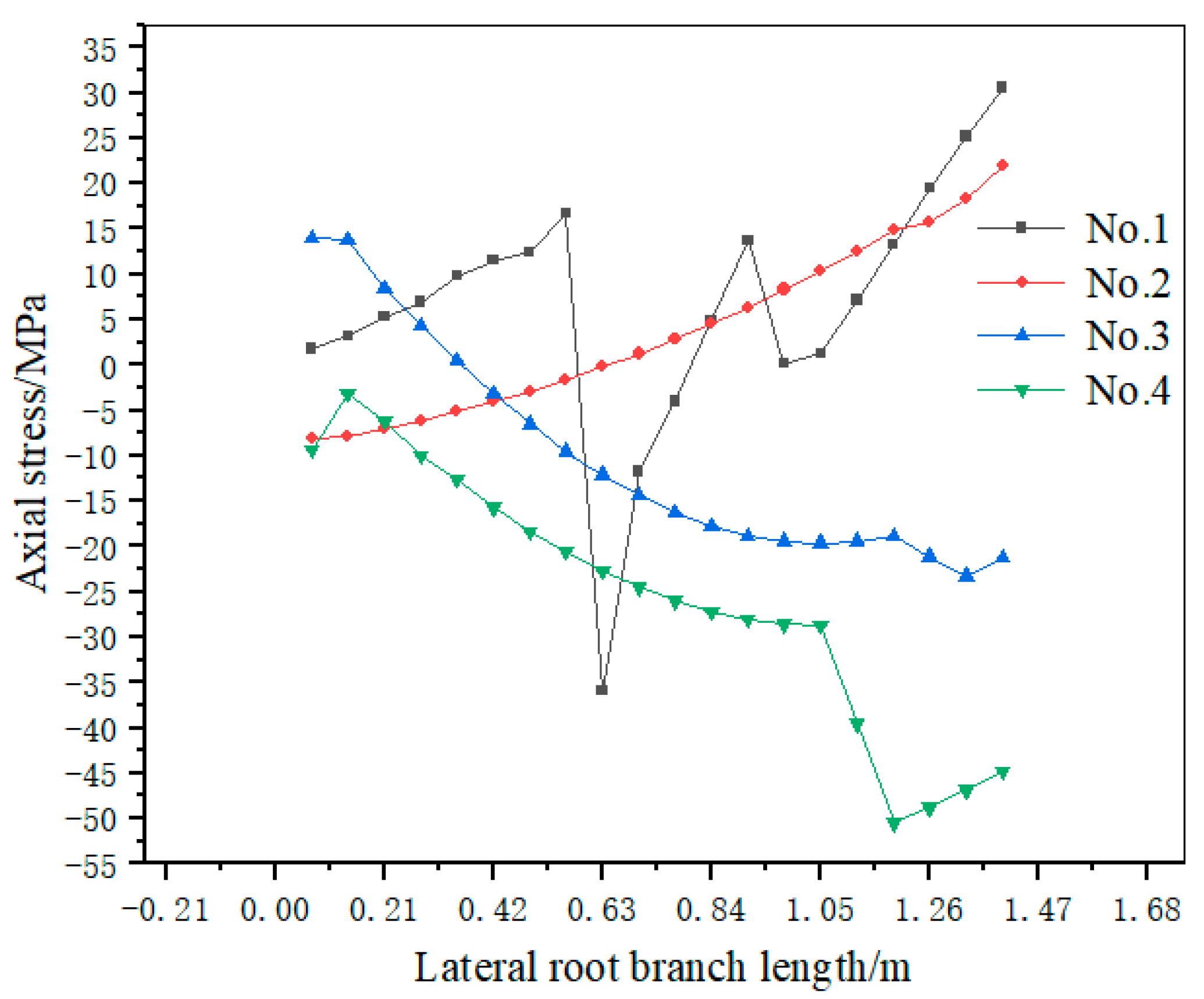
The root system with a 3 m tap root on the middle column of the slope toe was analyzed. For the symmetry of root distribution, lateral roots 1, 2, 3, and 4 were analyzed. Figure 10 shows that the No. 1 lateral root is mainly under tensile stress. The tensile stress first increases, then decreases, and then increases again, resulting in the maximum tensile stress at the root end. No. 2 lateral root is under compressive stress at its connection with the tap root; the compressive stress gradually decreases and then is under gradually increasing tensile stress, resulting in maximum tensile stress at the root end. No. 3 lateral root is under tensile stress at its connection with the tap root. The tensile stress gradually decreases, and then it is under gradually increasing compressive stress. No. 4 lateral root is mainly under compressive stress, and the compressive stress increases with the increase of its own branch length, and the maximum compressive stress generates at the root end.

3.3. Tap Roots Bending Moment Characteristics

Figure 11 shows the bending moment diagram of the 3 m-long tap root system of the living stump in the middle column, and when the front surface of the tap root is tensioned, the bending moment is positive. The buried depths for the maximum bending moment can be estimated by measurement tools in Midas. The tap root of living stumps of the first row is mainly under large positive bending moments. The maximum positive bending moment is generated at its buried depth of 0.75 m. The second to sixth rows of tap roots of living stumps are mainly under negative bending moments. The maximum negative bending moment of the tap root of the third-row living stumps is generated at its buried depth of 1.2 m. In addition, the negative bending moment value of the tap root of the fourth to sixth rows is getting smaller and smaller. It can be found that the maximum bending moment of the tap root of the first, third, fourth, and sixth rows of live stumps are all generated in the middle part, and the bending moment values at other positions are small and change slowly.

3.4. Lateral Roots Bending Moment Characteristics

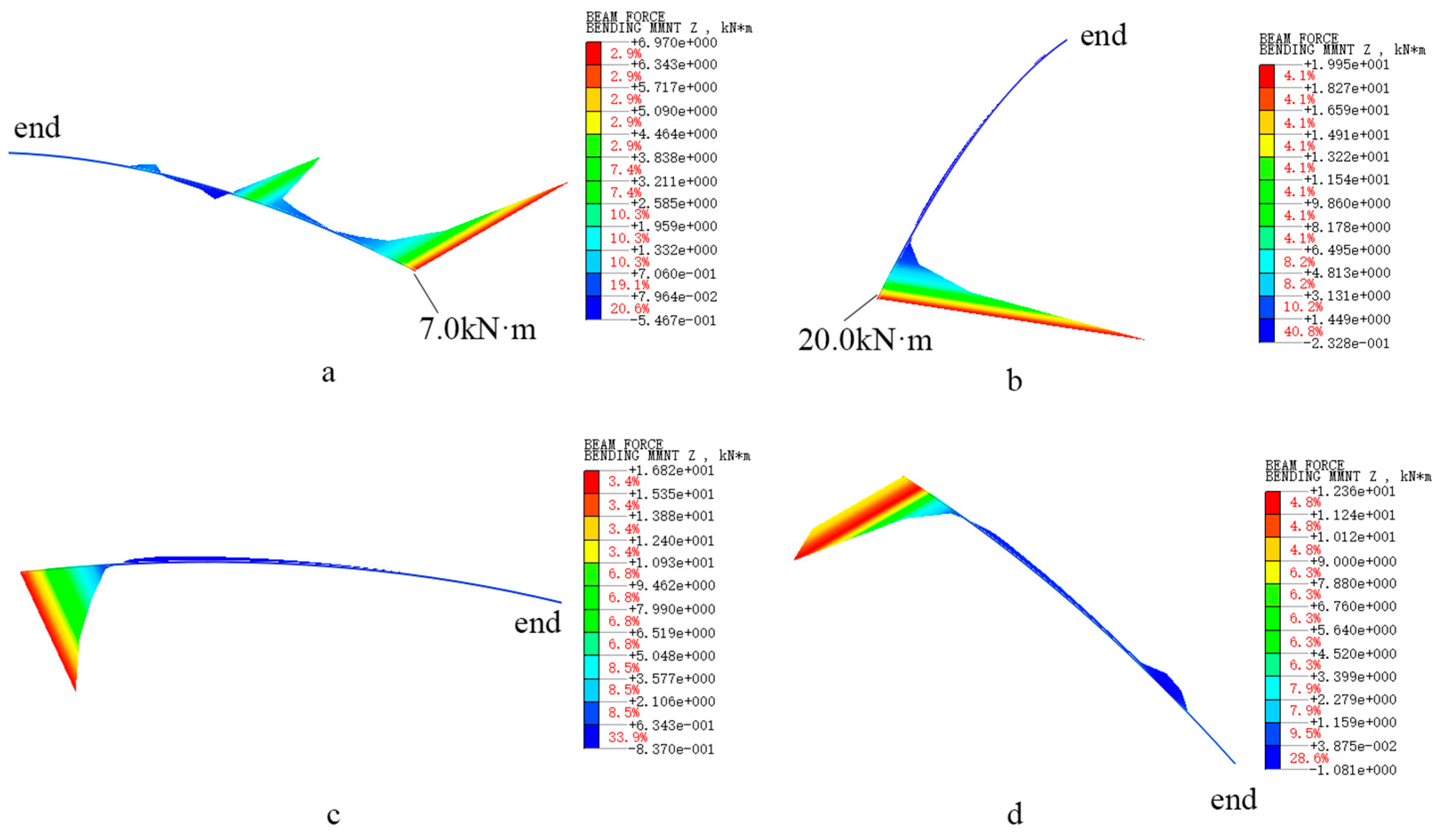
When the lower surface of the lateral root is tensioned, the bending moment takes a positive value. Figure 12 shows the bending moment of the first layer of lateral roots of the living stump with a 3 m-long tap root in the middle position of the first row. It can be seen from the figure that the maximum positive bending moment of No. 1–4 lateral roots are all generated at the connection with the tap root. The lower part of the lateral roots is in tension, and the bending moment value of the rest of the lateral roots is small and changes slowly. The No. 2 lateral root that grows laterally has the largest positive bending moment at its connection with the tap root, which is 20.0 kN·m, while the No. 1 lateral root growing towards the slope has the smallest positive bending moment at its connection with the tap root, which is 7.0 kN·m. During the sliding process of the slope due to its own weight, the connection between the lateral root and the tap root of the living stump at the slope toe is the main bending part. The lower surface of the lateral root is tensioned, and the No. 2 and No. 3 lateral roots that grow laterally have larger bending moment values.

4. Discussion

The later stage of a new type of living stump-bamboo anchor supporting structure [27] was simulated. Previous numerical works focused on modeling the root structure [37,38], while the new model developed in this paper was intended to explore the influence of living tree stumps on slope stability and the stress of the 3D root structure in the slope. This method could simulate the force state of living stumps on the slopes, which only a few people attempted before. The following section was devoted to the examination of these results and the evaluation of the potential and limitations of this new model.

4.1. The Slope Stability of Living Stumps in Different Growth Cycles

Live stumps with different growth periods contribute differently to slope stability. With the growth of the tree age, the tap root and lateral root of the living stump will become more and more developed, and the reinforcement effect on the slope will become better and better. In this paper, the influence of live tree stumps with three different growth periods (different main root lengths to simulate) on slope stability was considered. However, the effects of living tree stump planting and time on the slope stability were not taken into account.
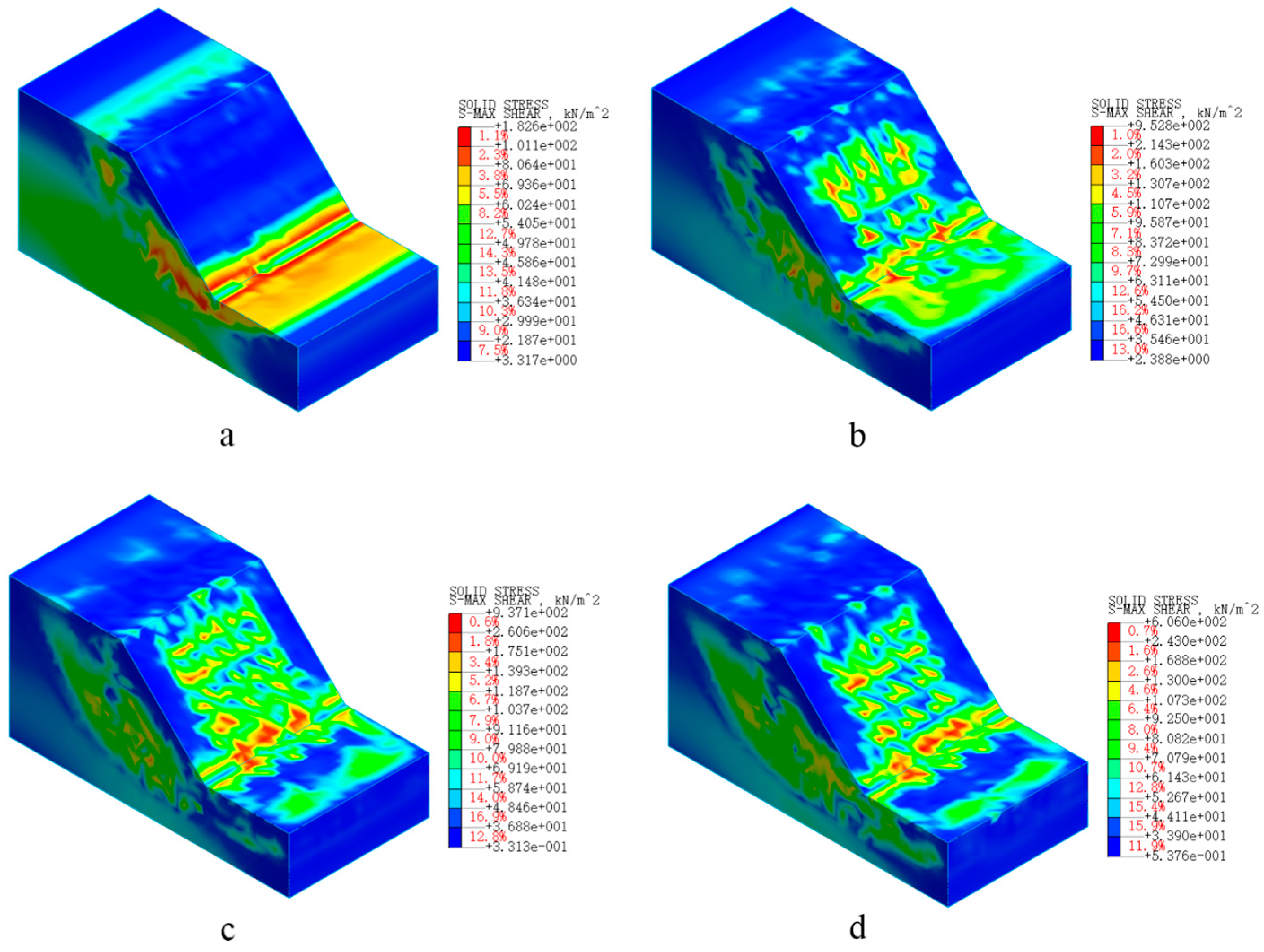
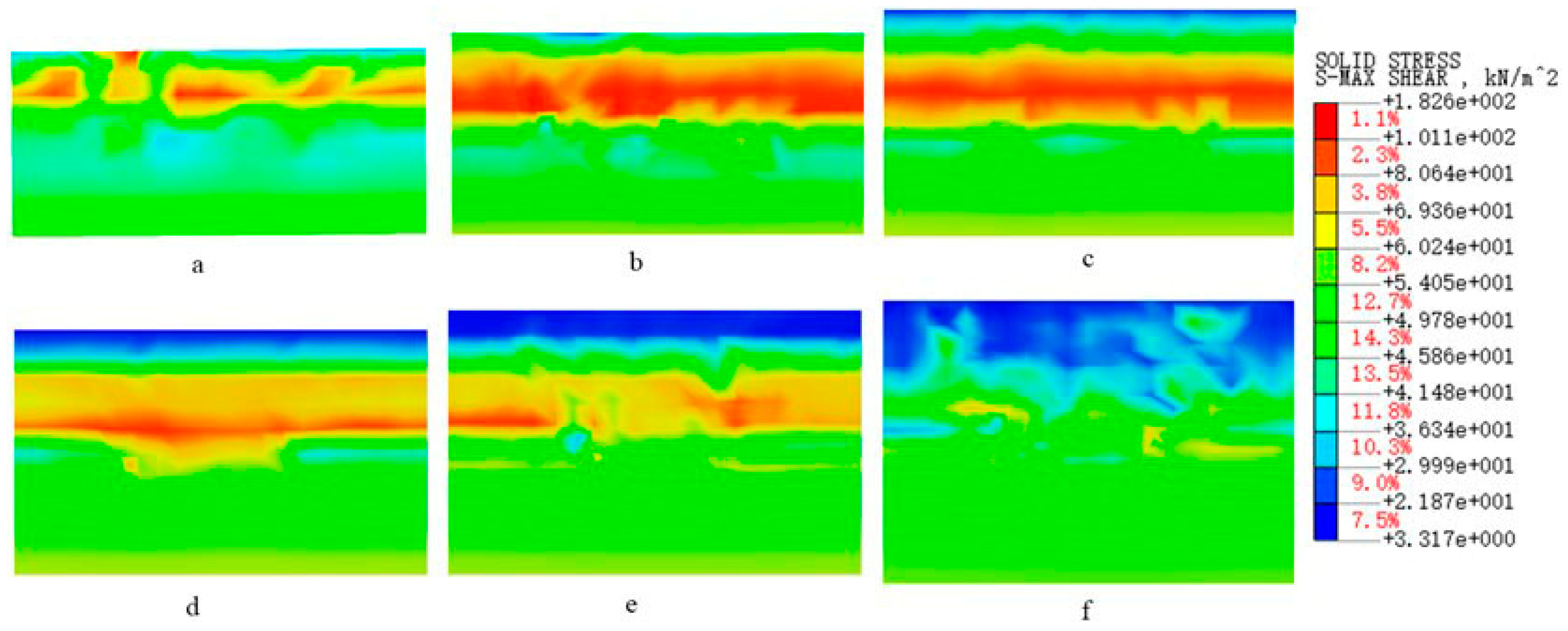
Figure 13 shows the shear stress of the bare and rooted slopes. The shear stress distribution of the bare slope is uniform, with the maximum shear stress concentrated at the foot of the slope, forming a connecting belt. While because of the existence of the root system (Figure 13b–d), the shear stress of the soil around the roots is greater. The longer the tap root, the more uniform the shear stress distribution of the soil on the slope, and the smaller the shear stress of the soil at the slope toe. The originally connected shear stress areas are separated, and the stability of the slope is improved. It is indicated that each row of roots in the slope tends to prevent the shear stress from spreading along the slope and improves the shear stress distribution of soil at the slope toe. The findings of [25] are consistent with our study. In addition, the arrangement distance of the root system on the slope, the incidence angle of the tap roots and the lateral roots, etc., all impact the slope stability [23,39].

4.2. The Shear Stress of the Soil at Different Positions of the Root System

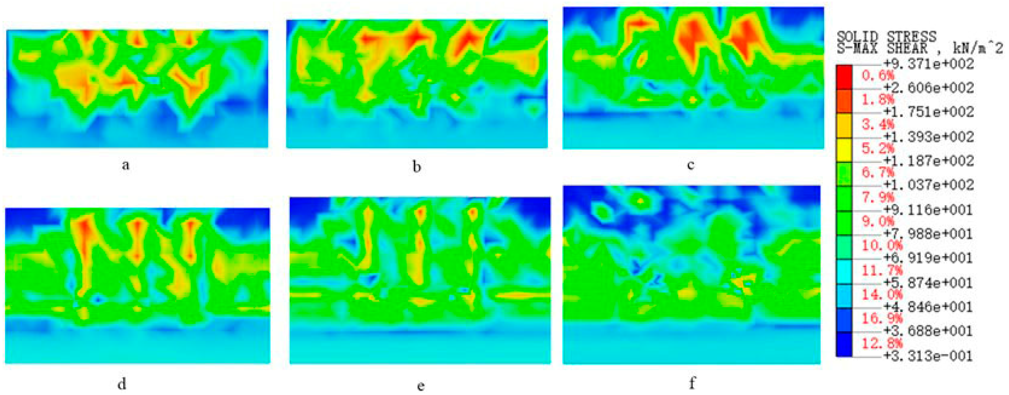
Since the stresses in roots depend on the surrounding soil, those in the soil are affected by the vicinity of the roots. In order to further explore the mechanical characteristic of living stump slopes, the shear stress diagrams of soil at different positions of the rootless slope section and 3 m root arrangement section are extracted. It can be seen from Figure 14a that the shear stress of the toe section of the unrooted slope is mainly concentrated at 2–3 m below the slope, while the shear stress of the 3 m tap roots slope is concentrated at the deeper soil layer (about 3–5 m) (Figure 15a). It indicates that the existence of the slope-toe roots makes the shear stress of the slope-toe soil move to the deeper soil layer, resulting in stress concentration. The originally penetrating shear stress concentration area is separated, which may be the key factor of the root system affecting slope stability. However, the shear stress of the soil around the lateral root system does not change significantly (Figure 15a–e), indicating that the existence of the lateral root system does not have much influence on the distribution of the slope soil shear stress. From Figure 15a–c, it can be seen that the shear stress of the soil around the first to third rows of root systems is relatively large, which means that these three rows of root systems play a significant role in preventing the propagation of shear stress along the slope. Nevertheless, the shear stress concentration in the surrounding soil where the roots of the fourth, fifth, and sixth rows exist is not obvious [17]. The results are consistent with those of [25]; that is, the root system in the middle and lower part of the slope has a major influence on the slope stability.

4.3. Root Mechanical Characteristics

A significant result of our research is related to the mechanical characteristics of roots. Embedded beam elements were used to simulate the root system. Due to the limitations of embedded beam elements, root slippage caused by large deformations of the root-soil system might not occur. Therefore, potential errors could arise due to the influence of the root-soil interface. Understanding the latest development in root-soil interactions could simulate root-soil interactions more accurately by incorporating friction laws of root-soil interaction [40,41,42].
The laws of friction are needed to calculate simple root-soil complexes. Due to the complexity of the model, it is difficult to achieve it in our research. Since the embedded element method turned out to be a good choice in accuracy [30], the stress state of the root system in the slope soil was well simulated, which enabled us to use the model to analyze the mechanical characteristics of different 3D root structures in the soil. The results showed that the thickness, length, and position of the root may strongly affect its force on the slope and its influence on the slope stability.
Compared with the root system in the upper part of the slope, the root system stress in the middle and lower parts of the slope is larger, contributing more to the anchorage of the soil [25]. No. 1 lateral root is mainly subjected to tensile stress, while the No. 4 lateral root is mainly subjected to compressive stress, which may be due to the symmetrical growth of the roots on both sides of the slope toe, and the No. 1 lateral root played an anchoring role, while the No. 4 lateral root did not. Additionally, the three rows of tap roots in the middle and lower part of the slope are also subject to greater bending moments, which may be related to the stress concentration of the surrounding soil. The bending moment of the lateral roots of the toe 1, 2, and 3 at the connection with the tap root is the largest, suggesting that when this kind of root structure is stressed in the slope, the lateral roots connected with the tap root are the most prone to bending deformation. It can help us understand how to optimize the root structure, which will have a good influence on the stability of the slope in the future. For the first time, we quoted the mechanical characteristics of the root system in slope stability analysis and specifically explored how the root system exerts its tensile strength to anchor the soil. In this research, due to the lack of specific data on root structure, it is necessary to simplify the root structure and the mechanical properties of certain roots. It is assumed that the mechanical properties of the tap root and lateral roots are the same, but their mechanical properties are not exactly the same. It is generally believed that there are differences due to the root age and physical properties of the root (cellulose, diameter, and water content) [43]. The elastic modulus of the root system used by us is 450 Mpa, which may cause calculation errors on all parameters related to the root system Es.
In addition, the simulation did not consider the impact of tree species planting and the weight of the trees on the slope. Li et al. showed that some trees on the ground had little influence on the total pressure of the slope [23]. Furthermore, this paper did not considere the physiological characteristics of the root system, such as water absorption. This physiological characteristic of roots will have a great impact on the mechanical properties of soil and roots, which are often dynamic and difficult to be simulated and analyzed qualitatively. As Matsushi et al. mentioned, rainfall was sometimes the determining factor of slope stability [44], though root architecture also had a great effect on soil loss. In conclusion, more experimental evidence is needed to improve and verify the 3D root slope model.

5. Conclusions

A 3D living stump slope model was established by using finite element software. The variable cross-section embedded beam elements were used to simulate the root structure of living stumps. The mechanical characteristics of living stump slopes with different taproot lengths were studied, suggesting that root systems in different growth periods had different reinforcement effects on slopes. The more developed the root system, the better the reinforcement effect on the slope. The tap roots in the middle and lower part of the slope mainly exert their tensile strength to achieve the effect of anchoring the soil.
The maximum shear stress region of soil moved towards a deeper soil layer because of the existence of roots. The longer the taproot, the better the anchorage. At the same time, the existence of the root system prevented the shear stress transfer along the slope and improved the problem of soil shear stress concentration at the slope foot. The model only studied the simplified root structure. Thus, in the future, more complex root structures should be analyzed in the model and combined with more realistic soil distribution. Nevertheless, our model is very useful for studying the mechanical characteristics of living stump slopes, which can help us to understand how to optimize the type of root structure in ecological slope protection engineering and select good tree species to protect slopes more effectively. For example, planting more live stumps with developed taproots and lateral roots growing towards the slope in the middle and lower part of the slope will improve slope stability. Different planting schemes can be added to study how to arrange live tree stumps to make the slope most stable.
In particular, under the influence of different factors such as rainfall, planting, and traffic load, the study of the mechanical characteristics of living stump slopes will help us to better apply the living tree stump slope protection technology.

Author Contributions

Conceptualization, X.J. and H.Y.; methodology, W.L. and X.J.; software, W.L. and H.Y.; formal analysis, X.J., Z.L. and W.F.; data curation, F.W.; writing—original draft preparation, W.L.; writing—review and editing, Z.L. and W.F. All authors have read and agreed to the published version of the manuscript.

Funding

The key construction discipline research ability enhancement project of Guangdong Province(Nos.2022JJ31005); The National Natural Science Foundation of China (Nos.31971727); The science and technology innovation Program of Hunan Province (Nos.2022NK2056); The Forest Science and Technology Innovation Program of Hunan Province (Nos.XLK202105-3); The Special Fund of Safety Production Prevention and Emergency Response of Hunan Province in 2021 (Nos.2021-QYC-10008-24956); Hunan Provincial Natural Science Foundation of China (Nos.2022JJ31005); The Key Project of Chongqing Natural Science Foundation(CSTC20JCYJ-ZDXMX0012); Open Fund of Engineering Research Center of Catastrophic Prophylaxis and Treatment of Road & Traffic Safety of Ministry of Education (Changsha University of Science & Technology: KFJ190401).

Institutional Review Board Statement

Not applicable.

Informed Consent Statement

Not applicable.

Data Availability Statement

The data presented in this study are available on request from the corresponding author.

Conflicts of Interest

The authors declare no conflict of interest.

References

  1. Fan, C.-C.; Chen, Y.-W. The effect of root architecture on the shearing resistance of root-permeated soils. Ecol. Eng. 2010, 36, 813–826. [Google Scholar] [CrossRef]
  2. Gray, D.H.; Leiser, A.T. Biotechnical Slope Protection and Erosion Control; Van Nostrand Reinhold Company Inc.: New York, NY, USA, 1982. [Google Scholar]
  3. Waldron, L.J. The Shear Resistance of Root-Permeated Homogeneous and Stratified Soil. Soil Sci. Soc. Am. J. 1977, 41, 843–849. [Google Scholar] [CrossRef]
  4. Wu, T.H.; McKinnell, W.P., III; Swanston, D.N. Strength of tree roots and landslides on Prince of Wales Island, Alaska. Can. Geotech. J. 1979, 16, 19–33. [Google Scholar] [CrossRef]
  5. Donn, S.; Wheatley, R.E.; McKenzie, B.M.; Loades, K.W.; Hallett, P.D. Improved soil fertility from compost amendment increases root growth and reinforcement of surface soil on slopes. Ecol. Eng. 2014, 71, 458–465. [Google Scholar] [CrossRef]
  6. McGuire, L.A.; Rengers, F.K.; Kean, J.W.; Coe, J.A.; Mirus, B.B.; Baum, R.L.; Godt, J.W. Elucidating the role of vegetation in the initiation of rainfall-induced shallow landslides: Insights from an extreme rainfall event in the Colorado Front Range. Geophys. Res. Lett. 2016, 43, 9084–9092. [Google Scholar] [CrossRef]
  7. Cohen, D.; Schwarz, M. Tree-root control of shallow landslides. Earth Surf. Dyn. 2017, 5, 451–477. [Google Scholar] [CrossRef]
  8. Bordoni, M.; Cislaghi, A.; Vercesi, A.; Bischetti, G.B.; Meisina, C. Effects of plant roots on soil shear strength and shallow landslide proneness in an area of northern Italian Apennines. Bull. Eng. Geol. Environ. 2020, 79, 3361–3381. [Google Scholar] [CrossRef]
  9. Eab, K.H.; Likitlersuang, S.; Takahashi, A. Laboratory and modelling investigation of root-reinforced system for slope stabilisation. Soils Found. 2015, 55, 1270–1281. [Google Scholar] [CrossRef]
  10. Donjadee, S.; Tingsanchali, S. Soil and water conservation on steep slopes by mulching using rice straw and vetiver grass clippings. Agric. Nat. Resour. 2016, 50, 75–79. [Google Scholar] [CrossRef]
  11. Nguyen, T.S.; Likitlersuang, S.; Jotisankasa, A. Influence of the spatial variability of the root cohesion on a slope-scale stability model: A case study of residual soil slope in Thailand. Bull. Eng. Geol. Environ. 2019, 78, 3337–3351. [Google Scholar] [CrossRef]
  12. Hunolt, A.E.; Brantley, E.F.; Howe, J.; Wright, A.N.; Wood, C.W. Comparison of native woody species for use as live stakes in streambank stabilization in the southeastern United States. J. Soil Water Conserv. 2013, 68, 384–391. [Google Scholar] [CrossRef]
  13. Wu, T.H.; Kokesh, C.M.; Trenner, B.R.; Fox, P.J. Use of Live Poles for Stabilization of a Shallow Slope Failure. J. Geotech. Geoenviron. Eng. 2014, 140, 05014001. [Google Scholar] [CrossRef]
  14. Greenwod, J.; Norris, J.; Wint, J. Paper for Geotechnical Engineering Special Issue. Geotech. Eng. 2004, 157, 199–207. [Google Scholar]
  15. Li, Y.; Wang, Y.; Wang, Y.; Ma, C. Effects of root spatial distribution on the elastic-plastic properties of soil-root blocks. Sci. Rep. 2017, 7, 1–11. [Google Scholar] [CrossRef] [PubMed]
  16. Hubble, T.; Docker, B.; Rutherfurd, I. The role of riparian trees in maintaining riverbank stability: A review of Australian experience and practice. Ecol. Eng. 2010, 36, 292–304. [Google Scholar] [CrossRef]
  17. Ji, J.; Kokutse, N.; Genet, M.; Fourcaud, T.; Zhang, Z. Effect of spatial variation of tree root characteristics on slope stability. A case study on Black Locust (Robinia pseudoacacia) and Arborvitae (Platycladus orientalis) stands on the Loess Plateau, China. Catena 2012, 92, 139–154. [Google Scholar] [CrossRef]
  18. Norris, J.E.; Stokes, A.; Mickovski, S.B.; Cammeraat, E.; Van Beek, R.; Nicoll, B.C.; Achim, A. Slope Stability and Erosion Control: Ecotechnological Solutions; Springer Science & Business Media: Berlin/Heidelberg, Germany, 2008. [Google Scholar]
  19. Song, W.F. Study on Physical Mechanism of Interface between Root System and Loess Soils; Beijing Forestry University: Beijing, China, 2006. (In Chinese) [Google Scholar]
  20. Liu, X.P. Finite Element Method Numerical Simulation of Forest Roots Reinforcement; Beijing Forestry University: Beijing, China, 2008. (In Chinese) [Google Scholar]
  21. Ji, X.L. A Roots Distribution-based Study on the Stability of Ecological Slope; Nanjing Forestry University: Nanjing, China, 2013. (In Chinese) [Google Scholar]
  22. Zhu, H.; Zhang, L.; Xiao, T.; Li, X. Enhancement of slope stability by vegetation considering uncertainties in root distribution. Comput. Geotech. 2017, 85, 84–89. [Google Scholar] [CrossRef]
  23. Li, Y.; Wang, Y.; Ma, C.; Zhang, H.; Wang, Y.; Song, S.; Zhu, J. Influence of the spatial layout of plant roots on slope stability. Ecol. Eng. 2016, 91, 477–486. [Google Scholar] [CrossRef]
  24. Danjon, F.; Barker, D.H.; Drexhage, M.; Stokes, A. Using three-dimensional plant root architecture in models of shallow-slope stability. Ann. Bot. 2008, 101, 1281–1293. [Google Scholar] [CrossRef]
  25. Fan, C.-C.; Lai, Y.-F. Influence of the spatial layout of vegetation on the stability of slopes. Plant Soil 2014, 377, 83–95. [Google Scholar] [CrossRef]
  26. Yang, M.; Défossez, P.; Danjon, F.; Fourcaud, T. Tree stability under wind: Simulating uprooting with root breakage using a finite element method. Ann. Bot. 2014, 114, 695–709. [Google Scholar] [CrossRef] [PubMed]
  27. Zhu, Y.; Yang, H.; Liu, Y.; Jiang, X.; Deng, R.; Huang, L.; Yin, P.; Lai, G. Numerical Simulation of the Combined Slope Protection Effect of Living Stump and Bamboo Anchor. Geotech. Geol. Eng. 2021, 40, 635–645. [Google Scholar] [CrossRef]
  28. Kokutse, N.; Fourcaud, T.; Kokou, K.; Neglo, K.; Lac, P. 3D numerical modelling and analysis of the influence of forest structure on hill slopes stability. Disaster Mitigation of Debris Flows, Slope Failures and Landslides. In Proceedings of the Interpraevent International Symposium, Niigata, Japan, 25–29 September 2006; pp. 561–567. [Google Scholar]
  29. Yen, C.P. Tree root patterns and erosion control. In Proceedings of the International Workshop on Soil Erosion and Its Countermeasures; Soil and Water Conservation Society of Thailand: Bangkok, Thailand, 1987; pp. 92–111. [Google Scholar]
  30. Ming, Y. Tree Root Anchorage: Modelling and Numerical Analyses of Key Contributing Factors of Wind Firmness of Pinus Pinaster. Ph.D. Thesis, Université de Bordeaux, Bordeaux, France, 2014. [Google Scholar]
  31. Watson, A.; Marden, M.; Rowan, D. Tree Species Performance and Slope Stability. Veg. Slopes Stabilisation Prot. Ecol. 1995, 161–171. [Google Scholar] [CrossRef]
  32. Wang, W.F.; Wu, F.S.; Xu, R.H.; He, D.P.; Qiu, F. Spatial distribution of root system at earthen ruins revealed by ground penetrating radar. J. Desert Res. 2015, 35, 1163–1170. (In Chinese) [Google Scholar]
  33. Li, Y.P. Research on Root Reinforcement Mechanisms and Evaluation of Vegetation Slope Stability in Beijing; Beijing Forestry University: Beijing, China, 2017. (In Chinese) [Google Scholar]
  34. Liang, T.; Knappett, J.A.; Duckett, N. Modelling the seismic performance of rooted slopes from individual root-soil interaction to global slope behaviour. Geotechnique 2015, 65, 995–1009. [Google Scholar] [CrossRef]
  35. Zhang, C.B. Fundamental and Mechanical Study on Soil Reinforcement and Slope Protection by Woody Plant Roots; Beijing Forestry University: Beijing, China, 2011. (In Chinese) [Google Scholar]
  36. Chen, Y.; Lin, H.; Cao, R.; Zhang, C. Slope stability analysis considering different contributions of shear strength parameters. Int. J. Geomech. 2021, 21, 04020265. [Google Scholar] [CrossRef]
  37. Dupuy, L.; Fourcaud, T.; Stokes, A. A numerical investigation into the influence of soil type and root architecture on tree anchorage. In Eco-and Ground Bio-Engineering: The Use of Vegetation to Improve Slope Stability. Developments in Plant and Soil Sciences; Stokes, A., Spanos, I., Norris, J.E., Cammeraat, E., Eds.; Springer: Dordrecht, The Netherlands, 2007; Volume 103. [Google Scholar] [CrossRef]
  38. Fourcaud, T.; Ji, J.-N.; Zhang, Z.-Q.; Stokes, A. Understanding the Impact of Root Morphology on Overturning Mechanisms: A Modelling Approach. Ann. Bot. 2008, 101, 1267–1280. [Google Scholar] [CrossRef]
  39. Ma, P.F.; Xia, D.; Xu, W.N.; Cheng, H.; Cai, C.F. Numerical simulation of the effect of plant roots on the stability of collapsing hillock. J. Disaster Prev. Mitig. Eng. 2019, 39, 354–364. (In Chinese) [Google Scholar] [CrossRef]
  40. Pollen, N. Temporal and spatial variability in root reinforcement of streambanks: Accounting for soil shear strength and moisture. Catena 2007, 69, 197–205. [Google Scholar] [CrossRef]
  41. Schwarz, M.; Cohen, D.; Or, D. Spatial characterization of root reinforcement at stand scale: Theory and case study. Geomorphology 2012, 171–172, 190–200. [Google Scholar] [CrossRef]
  42. Schwarz, M.; Giadrossich, F.; Cohen, D. Modeling root reinforcement using a root-failure Weibull survival function. Hydrol. Earth Syst. Sci. 2013, 17, 4367–4377. [Google Scholar] [CrossRef] [Green Version]
  43. Genet, M.; Stokes, A.; Salin, F.; Mickovski, S.B.; Fourcaud, T.; Dumail, J.-F.; Van Beek, R. The Influence of Cellulose Content on Tensile Strength in Tree Roots. Plant Soil 2005, 278, 1–9. [Google Scholar] [CrossRef]
  44. Matsushi, Y.; Hattanji, T.; Matsukura, Y. Mechanisms of shallow landslides on soil-mantled hillslopes with permeable and impermeable bedrocks in the Boso Peninsula, Japan. Geomorphology 2006, 76, 92–108. [Google Scholar] [CrossRef]
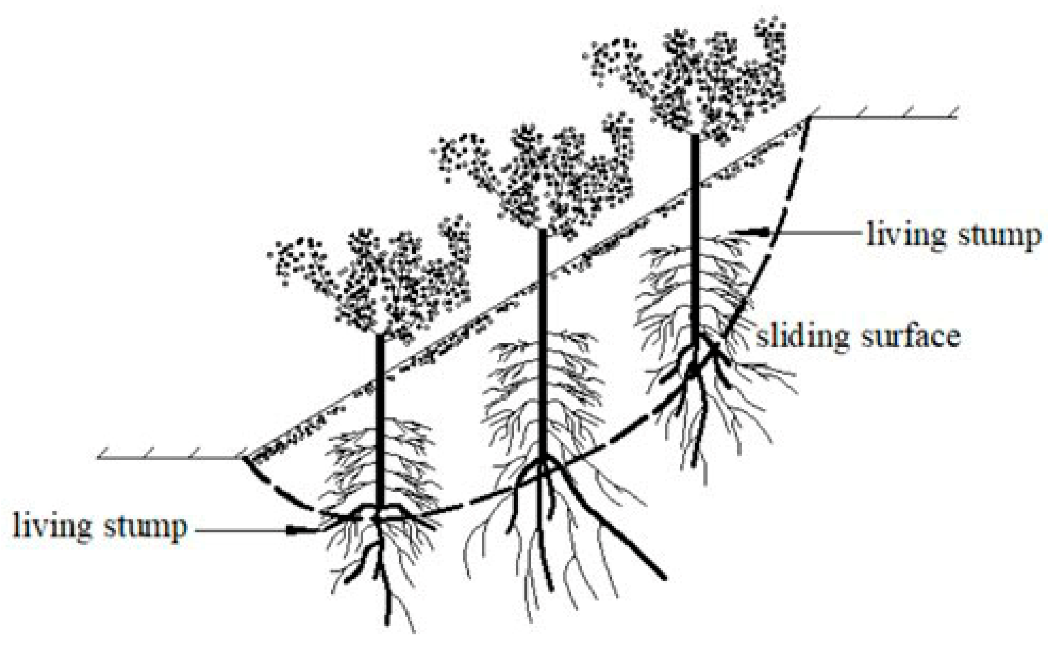
Figure 1. The slope reinforced with the living stump.
Applsci 13 01978 g001
Figure 2. The patterns of elm root architecture.
Applsci 13 01978 g002
Figure 3. 3D root system model of living elm stump with different tap root lengths.
Applsci 13 01978 g003
Figure 4. Variable cross-section groups.
Applsci 13 01978 g004
Figure 5. The Geometry of the Vegetated Slope: (a) Side view of the rooted slope, (b) 3D geometry of the slope, (c) Plan view of the rooted slope.
Applsci 13 01978 g005aApplsci 13 01978 g005b
Figure 6. Root system labeling diagram of slope toe (the first row).
Applsci 13 01978 g006
Figure 7. Equivalent plastic strain of slopes supported by tap roots with different lengths: (a) Bare slope, (b) 2 m tap root, (c) 3 m tap root, (d) 4 m tap root.
Applsci 13 01978 g007
Figure 8. The first to third rows tap roots stress.
Applsci 13 01978 g008
Figure 9. The fourth to sixth rows tap roots stress.
Applsci 13 01978 g009
Figure 10. The stress of the first layer lateral roots of the 3 m tap root.
Applsci 13 01978 g010
Figure 11. Tap root bending moment diagram of the first to sixth rows: (a) The first row, (b) The second row, (c) The third row, (d) The fourth row, (e) The fifth row, (f) The sixth row.
Applsci 13 01978 g011
Figure 12. Bending moment diagrams of the first layer lateral roots: (a) No. 1 lateral root, (b) No. 2 lateral root, (c) No. 3 lateral root, (d) No. 4 lateral root.
Applsci 13 01978 g012
Figure 13. The shear stress of the slope: (a) The bare slope, (b) 2 m tap root, (c) 3 m tap root, (d) 4 m tap root.
Applsci 13 01978 g013
Figure 14. The shear stress of the soil at the cross-section of the rootless slope: (a) The slope toe, (b) The second row, (c) The third row, (d) The fourth row, (e) The fifth row, (f) The sixth row.
Applsci 13 01978 g014
Figure 15. The shear stress of the soil at the 3 m root slope section: (a) The slope toe, (b) The second row, (c) The third row, (d) The fourth row, (e) The fifth row, (f) The sixth row.
Applsci 13 01978 g015
Table 1. Parameters of tap roots and lateral roots.
Tap Root Length and Diameter Lateral Root LengthLateral Root Diameter
Tap Root
Length/m
Tap Root
Diameter/m
The First Layer Lateral
Root/m
The First Layer Lateral
Root/m
2 m0.1–0.051.00.08–0.05
3 m0.2–0.11.40.15–0.05
4 m0.3–0.152.00.20–0.05
Table 2. Properties of the soils and roots.
E/MPaγ (kN/m3)μC (kN/m2)ϕ (°)
Soil15150.441820
Root45011.370.3----
Table 3. Safety factors of different slopes.
Work ConditionsBare2 m Tap Roots3 m Tap Roots4 m Tap Roots
Safety factors0.9941.1121.3001.400
Disclaimer/Publisher’s Note: The statements, opinions and data contained in all publications are solely those of the individual author(s) and contributor(s) and not of MDPI and/or the editor(s). MDPI and/or the editor(s) disclaim responsibility for any injury to people or property resulting from any ideas, methods, instructions or products referred to in the content.