Abstract
The disturbance depth of traffic load has a direct impact on the stability of a room-and-pillar mining goaf. To quantitatively calculate the relationship between the traffic load disturbance depth and influencing factors, 49 groups of horizontal combinations of different influencing parameters are designed in this study, based on the orthogonal experimental design method. Midas GTS is used to simulate and obtain the corresponding traffic load disturbance depth data. A multivariate linear regression analysis of the traffic load disturbance depth is conducted, and a regression formula for calculating the traffic load disturbance depth is established. According to the traffic load disturbance depth, goaf depth, and the stability of the roof, coal pillar, and base plate under traffic load conditions, a judgment flow of the room-and-pillar mining goaf treatment method under traffic load conditions is established, and it is applied to the reconstruction and expansion project of the Jixi section of the Dan-A national highway. The results show that a geogrid can be used for treatment purposes when the traffic load disturbance depth is 1.5 times lower than the depth of the room-and-pillar mining goaf, or when the traffic load disturbance depth is 1.5 times greater than the depth of the room-and-pillar mining goaf but the roof, coal pillar, and base plate are stable. Additionally, grouting is needed for treatment in other cases. The results of this study can provide a scientific basis for the selection of treatment methods for room-and-pillar mining goafs underlying highways in the future. The results are of great significance in the field of engineering for the safety measures concerning highway room-and-pillar mining goafs.
1. Introduction
The reconstruction and expansion project of the Jixi section of the Dan-A national highway passes through the Muling, Pinggang, and Hengshan mines, as well as other mining areas. Influenced by certain factors, such as mining technology, conditions, and planning, early coal seam mining methods that were commonly used in the field were room-and-pillar mining methods. Although the size, shape, mining depth, and overlying strata of goafs in the different mining areas under study were different, the overlying rock mass was mostly in a stable state and did not collapse as a result of the small, mined-out span and support from the coal pillars. However, the new roads being built and the application of traffic loads, such as a roadbed, pavement, and vehicles, to this type of goaf will likely disrupt the original stress balance, resulting in the instability of the supporting coal pillars and the sudden fall of an overlying rock mass in the mined-out area. This could result in a sudden subsidence of the ground surface, which would damage the subgrade and pavement and cause the vehicles to overturn or fall into the collapsed area, thus resulting in personal casualties or property losses [1,2,3].
Based on this determination, domestic and foreign scholars have conducted extensive research on the stability of room-and-pillar mining goafs. Regarding the issue of coal pillars, research has been conducted on the conditions that affect their stability [4], the characteristics that signify their instability and failure [5], their pressure relief properties [6], the evaluation method used for coal-pillar stability assessments [7], and the calculation formula used for coal-pillar strength assessments [8]. In relation to the issue of the roof, research has been conducted on the influencing factors of roof stability [9], including the safe thickness property of a roof [10] and the total span of the roof [11], as well as other issues. Some scholars have also evaluated the coupling of a coal pillar and roof [12]. The research that has been conducted on the issue of traffic load include the law of transmission and the diffusion of the traffic load [13], the effect of the model of the vehicle load [14], the dynamic response of soil under traffic load conditions [15], and road subsidence under heavy traffic load conditions [16].
For roads built on goaf areas, grouting is often used in engineering practices to treat these goaf areas to avoid the hidden dangers of road construction and operation, such as surface subsidence and roadbed collapse, caused by the sudden instability of the goaf areas [17,18,19,20,21]. Although this form of treatment can solve the above-mentioned hidden dangers, it also leads to a substantial increase in construction costs. With the expansion of research in this area, some scholars have proposed that when a coal pillar and a roof in goafs are stable under traffic load conditions, it is then only necessary to lay a geogrid on the subgrade for treatment without using grouting to fill the goaf [22]. Thus, the key to the treatment of a subgrade with a geogrid is to determine the stability of the coal pillar and roof in the goaf under the traffic load. However, the method of evaluating the coal pillar and roof stability in the goaf under the traffic load—although it was involved in the previous research—is not perfect or universal (such as simplifying the traffic load to a static load without considering the influence of the dynamic vehicle load, or using the disturbance depth relative to the mining depth as a judgment method in which the bearing capacity of the coal pillar and roof are not considered).
Therefore, it is of great practical significance to study the stability of coal pillars and roofs in goaf areas under traffic load conditions, propose a general method for calculating the stability of goaf areas in different road sections and mining areas, and then judge the treatment measures suitable for this road section and mining area, so as to optimize the treatment time of goaf areas, avoid the collapse of goaf areas, and ensure the stable and safe operation of the overlying highway during its service life.
The remaining structure of this paper is as follows: Section 2 introduces the stability analysis of a goaf under traffic load conditions; Section 3 introduces the applicability analysis of the two treatment methods used in this study; Section 4 introduces an engineering case analysis of the treatment judgment method proposed in this paper; Section 5 introduces the novelty of the research content, the research results, and a discussion of the shortcomings; and Section Six presents the research conclusions.
2. Stability Analysis of a Goaf under Traffic Load Conditions
2.1. Analysis of Traffic Load Disturbance Depth
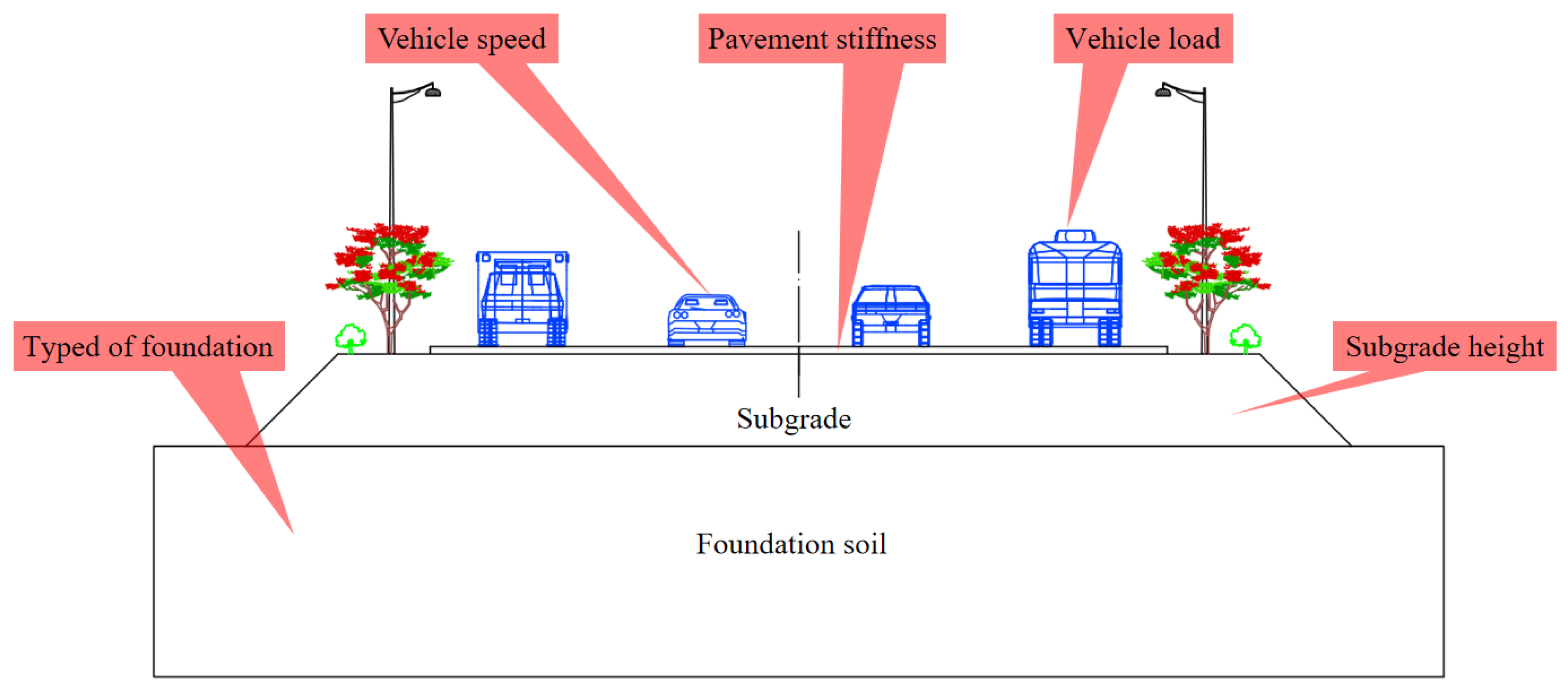
The disturbance depth of a traffic load is mainly related to the subgrade height, pavement stiffness (different pavement stiffnesses are represented by changing the elastic modulus of the pavement materials), foundation type (different types of foundations are represented by changing the unit weight of the foundation rock and soil), vehicle load, and vehicle speed [23], as presented in Figure 1. Different subgrade heights, pavement stiffness values, vehicle speeds, vehicle loads, and typed of foundations will affect the disturbance depth of a traffic load. To quantitatively calculate the relationship between the traffic load disturbance depth and the abovementioned factors, Midas GTS was used to calculate the traffic load disturbance depth under different influencing factors, and a multiple regression was used to fit the calculation formula of the traffic load disturbance depth.
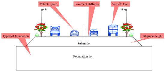
Figure 1.
Schematic diagram of influencing factors of traffic load disturbance depth.
2.1.1. Numerical Simulation of Traffic Load and Discriminant Conditions of Disturbance Depth
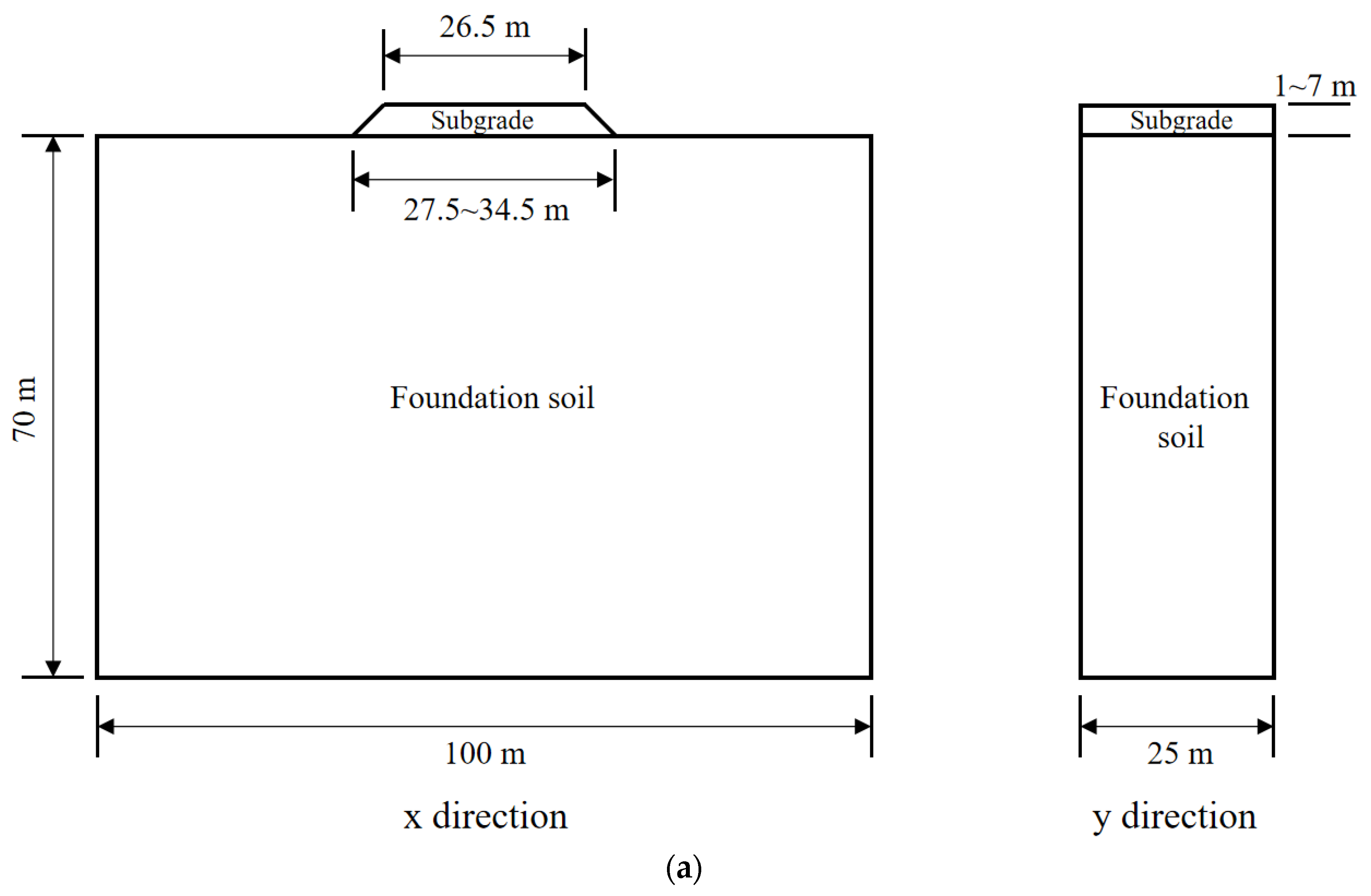
Numerical simulation. Midas GTS software was used to establish the calculation model of traffic load disturbance depth. The schematic diagram of the model is presented in Figure 2. The x direction of the model is the cross-section direction of the road, and the y direction is the longitudinal-section direction of the road, where the length × width × height of the model under the road = 100 m × 25 m × 70 m, and the width of the bottom of the subgrade is 27.5~34.5 m, according to the subgrade height of 1~7 m; that is, a slope ratio of the subgrade slope of 1:1. During the grid division, smaller grid sizes were adopted for the subgrade, surface layer, base layer, and foundation, and the model as a whole was distributed from the subgrade to the surrounding boundary from dense to sparse.
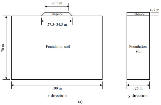
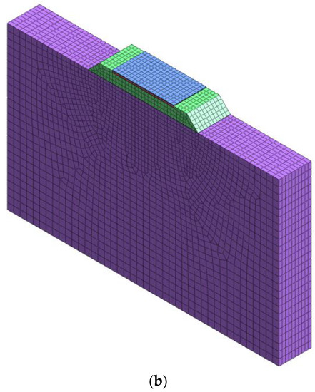
Figure 2.
Schematic diagram of numerical calculation model of traffic load disturbance depth. (In the numerical model, the thickness of the surface layer is set to 0.2 m, and that of the base layer is set to 0.4 m). (a) Numerical simulation model dimensions, (b) schematic diagram of a three-dimensional numerical simulation model.
This model was divided into four parts: the surface layer, base layer, subgrade, and foundation. The parameter settings of each layer are presented in Table 1. The surface and base layers were set as linear elastic constitutive models, and the subgrade and foundation were set using the Mohr–Coulomb constitutive model. The calculation of the model was performed in two steps. First, prior to analyzing the disturbance depth of the traffic load, the boundary constraint condition of the model was set as the elastic boundary. An eigenvalue analysis was then conducted under this boundary condition to obtain the periodically calculated damping coefficient and maximum modal frequency of the model. Second, following the eigenvalue calculation, the boundary condition was changed from an elastic to viscous absorption boundary, the vehicle load condition was set, and the periodic calculation damping coefficient and maximum modal frequency were set, which were calculated in the first step in the analysis settings to begin the analysis and calculation of the traffic load disturbance depth (the purpose of setting the viscous absorption boundary was to prevent the traffic load from bouncing back when it was transferred to the boundary, which affects the correctness of the analysis results).

Table 1.
Parameters of materials.
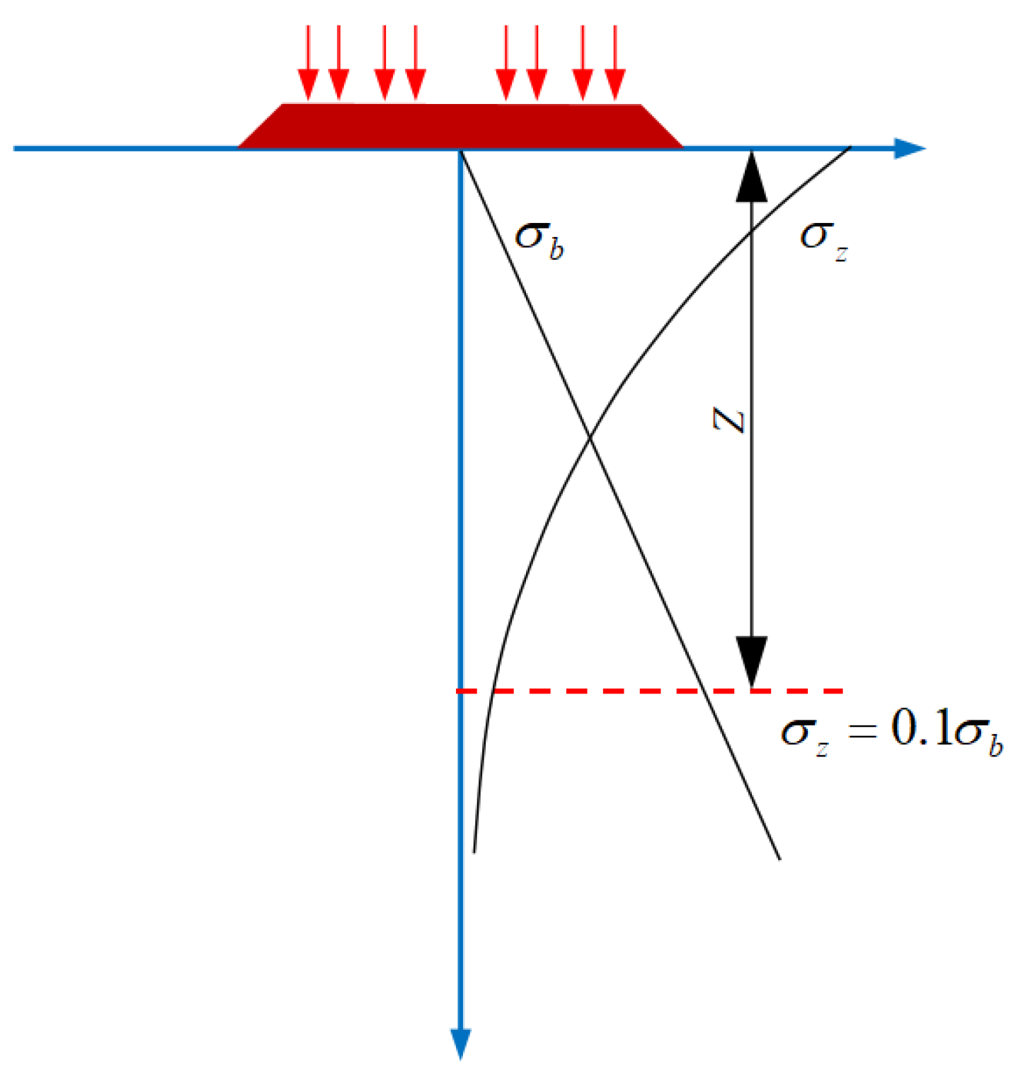
Discriminant conditions. Disturbance depth is related to the foundation type and load size. Combined with domestic and foreign research results and engineering experience, it can be determined that when the additional stress, of a traffic load in the foundation is lower than 10% of the self-weight stress, of soil (presented in Figure 3), it is considered that the additional stress will no longer affect the deformation of soil at this depth and below [28], and depth Z can be taken as the disturbance depth of the traffic load.

Figure 3.
Schematic diagram of traffic load disturbance depth.
2.1.2. Orthogonal Design of the Traffic Load Disturbance Depth Parameter and Its Calculation Results
Orthogonal design is the most important method in a multifactor simulation experiment. This method is a multi-factor simulation test method [29] that is based on the fractional principle of factor design. It uses an orthogonal table derived from combination theory to arrange and design simulation tests. The results are then statistically analyzed.
In this orthogonal design, we selected five influencing factors as the study objects. Each factor had seven levels, presented in Table 2. The factors refer to the items that affected the simulation test results, and the levels refer to the size and level of each factor in the simulation test process. According to the principle of orthogonal design, we used the L49(75) orthogonal table to arrange the orthogonal simulation test of five factors and seven levels. Then, we obtained an orthogonal design table for the levels of traffic load disturbance depth parameter factors, presented in Table 3. Table 3 shows that we obtained 49 groups of different levels of combinations of traffic load disturbance depth parameter factors, corresponding to 49 rows in the orthogonal table; that is, the number of simulation tests was 49. We calculated each simulation of the disturbance depth according to a set of parameter levels presented in Table 3, and the calculated disturbance depth was recorded. Following 49 simulations, the results of the traffic load disturbance depth under different combinations of influencing factors and parameters are presented in Table 3.
Table 2.
Traffic load disturbance depth parameter level table.
Table 3.
Orthogonal table of a horizontal combination of L49(75) parameters and calculation results of the disturbance depth of traffic load.
2.1.3. Multiple Linear Regression of Traffic Load Disturbance Depth
This study preliminary adopted five parameters, H, E, V, G, and γ, as independent variables and a disturbance depth, Z, as the dependent variable. The study utilized multiple linear regression to quantitatively analyze the relationship between each influencing factor and the disturbance depth, which is used to judge the correlation between the influencing factors and the disturbance depth and the significance of the influencing factors.
The numerical simulation results for each parameter level combination and its disturbance depth, presented in Table 3, were fitted by multiple linear regression, and the fitting degree and fitting results are presented in Table 4 and Table 5.
Table 4.
Statistical table of multiple linear regression results.
Table 5.
Parameter table of multiple linear regression results.
It can be observed from Table 4 that the R2 between the dependent and independent variables is 0.932, which indicates that the five influencing factors selected in this study have a strong correlation with the depth of the traffic load disturbance. The adjusted R2 is 0.925, which indicates that the five influencing factors selected in this study can effectively express the change in the traffic load disturbance depth. Further analysis of the significance of the influencing factors shows that when the significance level of 0.05 is adopted, it can be observed from the significance of each factor in Table 5 that the subgrade height, pavement stiffness, vehicle speed, and vehicle load are the significant influencing factors, while the significance of the foundation soil unit weight is 0.272, meaning it is a non-significant influencing factor. Therefore, in the multiple linear regression fitting, the factor of foundation soil unit weight should not be included. After eliminating this factor, the multivariate linear regression fitting was performed again on the numerical simulation results of each parameter level combination and its disturbance depth in Table 3. The fitting degree and fitting results are shown in Table 6 and Table 7.
Table 6.
Statistical table of multiple linear regression results after re-fitting.
Table 7.
Parameter table of multiple linear regression results after re-fitting.
After analyzing the re-fitting results in Table 6 and Table 7 according to the analysis process of the preliminary fitting, we observed that the four selected influencing factors could effectively express the change in the traffic load disturbance depth, and that the selected factors were all significant influencing factors. Therefore, the fitting of a multivariate linear regression equation could be carried out. Considering the regression coefficients of each parameter in Table 7, the multivariate linear regression equation of disturbance depth Z with the H, E, V, and G parameters is presented in Formula (1):
2.2. Checking the Calculation of Roof Strength under Traffic Load Conditions
Because the collapse of a roof may cause the sudden collapse of the surface, which will result in quite severe consequences to the operation of a highway, the safety check of the roof is a particularly important step. Under the double action of the traffic load and the overlying strata, the stress of the roof is complicated, and the Whittaker method is a common calculation method used in practical engineering at present.
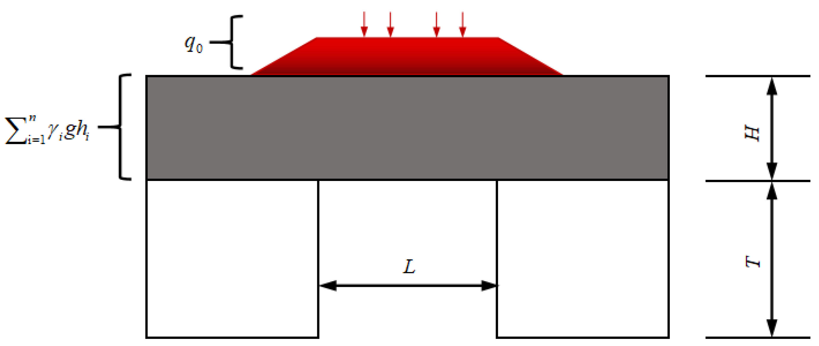
The Whittaker method is a method based on structural mechanics which is used to check the strength of the roof [30]. In this method, the roof and coal pillar are simplified into simply supported beam structures, and the traffic load borne by the roof and load generated by the dead weight of the overlying strata are considered to be uniformly distributed loads, as presented in Figure 4. The maximum tensile stress (MPa) of the roof is calculated as follows:
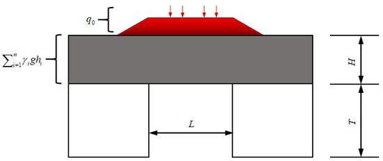
Figure 4.
Schematic diagram of the Whittaker method calculation.
In Formula (2), H is the thickness of the roof; is the weight of the overlying rock mass; g is the gravitational acceleration; is the thickness of each layer of rock mass; is the traffic load; and L is the coal pillar spacing.
After calculating the maximum tensile stress of the roof, compare it with the tensile strength of the roof strata, and the calculation formula is
In Formula (3), is the tensile strength (MPa) of the roof strata, and k is the safety factor. Referring to the evaluation of the stability grade of a roadway goaf in the Technical Rules for Highway Design and Construction of Goaf Areas [22] and the evaluation standard [31] of the influence of the critical influence depth of load on the stability of goaf areas in the Code for Geotechnical Engineering Investigation of Coal Goaf Areas, when K > 1.5, the roof can be considered safe and stable for a long period of time and will not collapse under traffic load conditions (as geotechnical engineering is a discipline with many empirical factors, and we cannot be completely accurate in actual engineering, some errors will always exist. To ensure the safe operation of the project within its service life, we should keep a safety reserve in the design. When the safety reserve exceeds 0.5 times in the project, it can generally guarantee safe operation, so a safety factor of 1.5 times was adopted).
2.3. Strength Calculation of a Coal Pillar and Base Plate under Traffic Load Conditions
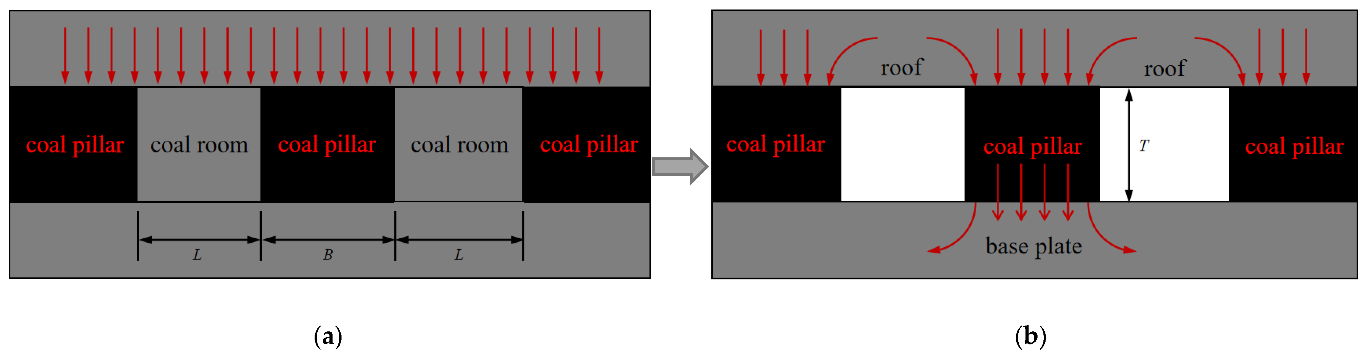
After the coal in the coal room is mined, the mechanical balance in the original rock mass is disrupted, the stress is redistributed, and the load acting on the coal room is transferred to the coal pillar and transmitted to the base plate, as presented in Figure 5:

Figure 5.
Changes in coal pillar load prior to and following the excavation. (a) The coal room is not excavated; (b) coal room excavation.
The strength inspection of the coal pillar can allow us to judge whether it can remain stable under traffic load conditions, and the strength inspection of the base plate can allow us to judge whether it can bear the pressure from the coal pillar under traffic load conditions. Structural mechanics can be used to calculate the average vertical stress in the coal pillar. Assuming that the coal pillar bears the weight of the overlying rock mass, the average vertical stress (MPa) in each coal pillar is
In the formula above, B is the width of the coal pillar, and the rest are the same as above.
The strength (MPa) of a coal pillar is related to its shape and its width–height ratio. A square coal pillar is often used in engineering. For the square coal pillar, Salamon, a South African scholar, proposed an empirical calculation formula [32] based on numerous experiments:
In the formula above, T is the height of the coal pillar.
After calculating the average vertical stress and strength of the coal pillar using Formulas (4) and (5), respectively, the safety factors of the coal pillar and base plate can be calculated using Formulas (6) and (7), respectively:
In the formula, is the compressive strength of the base plate (MPa). When K > 1.5, it can be considered that the coal pillar and base plate can remain stable for a long period of time, and there will be no instability under traffic load conditions.
3. Applicability Analysis of Treatment Methods
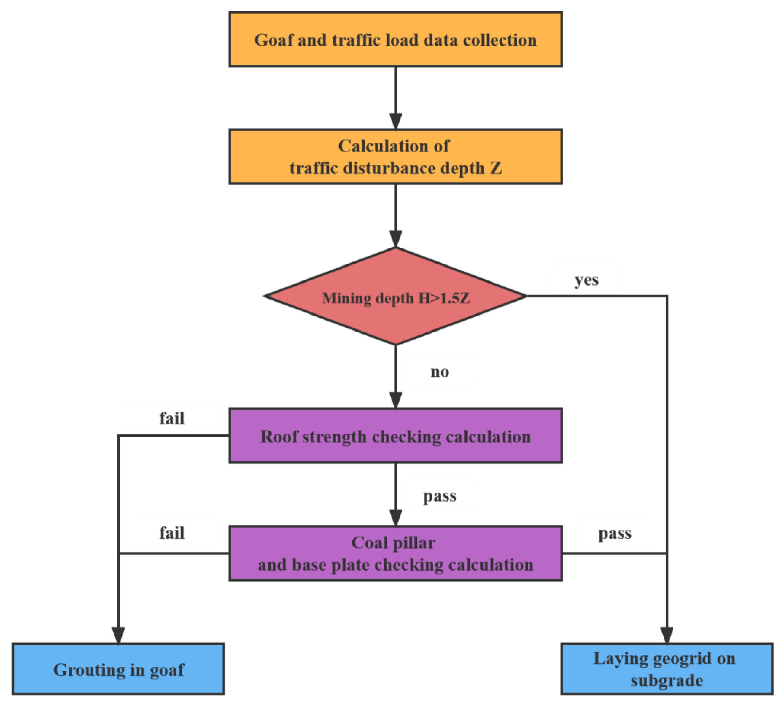
Combined with the analysis of the disturbance depth and stability of the roof, coal pillar, and base plate in the first chapter, the treatment method of room-and-pillar mining goafs under traffic load conditions in practical engineering can be judged according to the process presented in Figure 6.

Figure 6.
Judgment process of the treatment method. (Note: The depth of the goaf area is less than 1.5 times the maximum load disturbance depth because it was considered that the coal pillar and roof of the room–pillar goaf area had a certain bearing capacity. If its bearing capacity was more than 1.5 times the sum of the dead weight of the overlying strata and the additional stress caused by traffic load, the room-pillar goaf was considered to be capable of remaining stable for a long time under traffic load).
In the process presented in Figure 6, geophysical prospecting, drilling, laboratory tests, and data collection should first be used to determine the following factors: (1) the depth of the goaf area, the distance between the pillars, and the width and height of the coal pillars; (2) the thickness and tensile strength of the roof of each rock and soil layer in the goaf; and (3) the subgrade height, pavement stiffness, vehicle speed, and maximum vehicle load of the goaf area. After the information mentioned above was successfully determined, the disturbance depth of the traffic load in the road section was calculated using the formula (1). If the mining depth was 1.5 times greater than the disturbance depth [31], it could be determined that the subgrade can be treated by laying a geogrid. If the mining depth was 1.5 times less than the disturbance depth, checking calculations for the roof, coal pillar, and base plate are required. When the checking calculation of the traffic load disturbance depth is not thorough enough, the tensile stress and safety factor values of the roof are calculated according to Formulas (2) and (3), respectively. If the safety factor is greater than 1.5, the stability values of the coal pillar and base plate need to be checked; if it is less than 1.5 [22], grouting treatment can be determined. After the roof check has been passed, the average vertical stress and strength of the coal pillar can be calculated according to formulas (4) and (5), respectively, and then the safety factors of the coal pillar and base plate can be calculated according to formulas (6) and (7), respectively. If both present values greater than 1.5, it can be determined that the subgrade will be treated by laying a geogrid; otherwise, grouting treatment is required.
4. Engineering Case Analysis
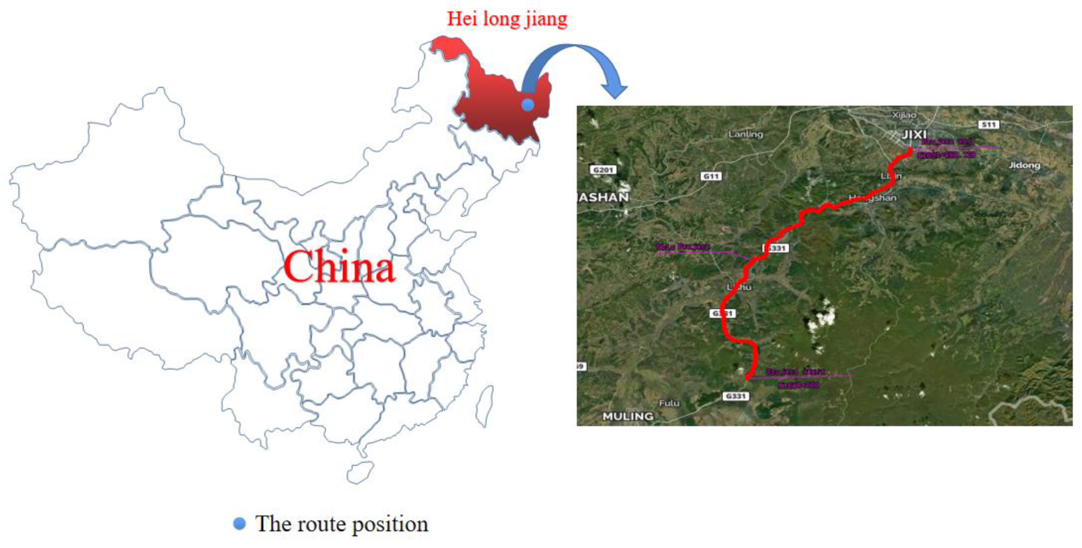
The reconstruction and extension project of the Jixi section of the Dan-A national highway is a first-class highway with a design speed of 80 km/h and a roadbed width of 25.5 m. The starting and ending pile numbers of the project are K1600 + 000~K1651 + 498.739, and the total length of the route is 51.478 km, among which the old goaf areas are K1605 + 000~K1628 + 660 and K1631 + 985~K1647 + 100, with a total length of 38.775 km. The road location map is presented in Figure 7.
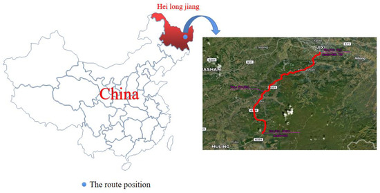
Figure 7.
Location map of the highway route.
Geophysical exploration, drilling, laboratory tests, and data collection were conducted on the room-and-column goaf during the reconstruction and extension project of the Jixi section of the Dan-A national highway. The relevant data for the goaf are presented in Table 8. Considering the design documents, the traffic load parameters of the road sections corresponding to the goaf areas are presented in Table 9:
Table 8.
Parameters of goafs in sections with room-and-pillar goaf areas.
Table 9.
Parameters of traffic load in sections with room-and-pillar goaf areas.
Taking the analysis of the K1631 + 985~K1632 + 035 pile number as an example, this study expounded the applicability analysis of the treatment method of room-and-pillar mining goaf areas in detail, in combination with the evaluation process of the treatment method presented in Figure 6. Firstly, the traffic load parameters presented in Table 9 were included in Formula (1), and the maximum load disturbance depth of the road within the service life was calculated to be 14.89 m. In comparison to the depth of the room-and-pillar goaf areas presented in Table 8, which is 22 m, it can be observed that the goaf area depth is smaller than 1.5 times the maximum load disturbance depth. Therefore, it was necessary to perform a strength inspection of the roof, coal pillar, and base plate. The parameters presented in Table 8 were included in Formula (2), and the tensile stress of the roof under traffic load conditions was calculated to be 0.283 MPa. This value was then included in Formula (3), and the calculated K was 2.47, which is greater than 1.5. It was therefore necessary to check the strength of the coal pillar and base plate. After the parameters were included in Formulas (4) and (5), the compressive stress of the coal pillar under traffic load conditions was determined to be 13.867 MPa, and the strength of the coal pillar was 15.845 MPa. After these parameters were included in Formulas (6) and (7), the values of K were 1.14 and 1.66, respectively. As the safety factor of the coal pillar was 1.14, the coal pillar may be unstable under traffic load conditions in this road section. Therefore, grouting treatment should be performed in the goaf area under this road section.
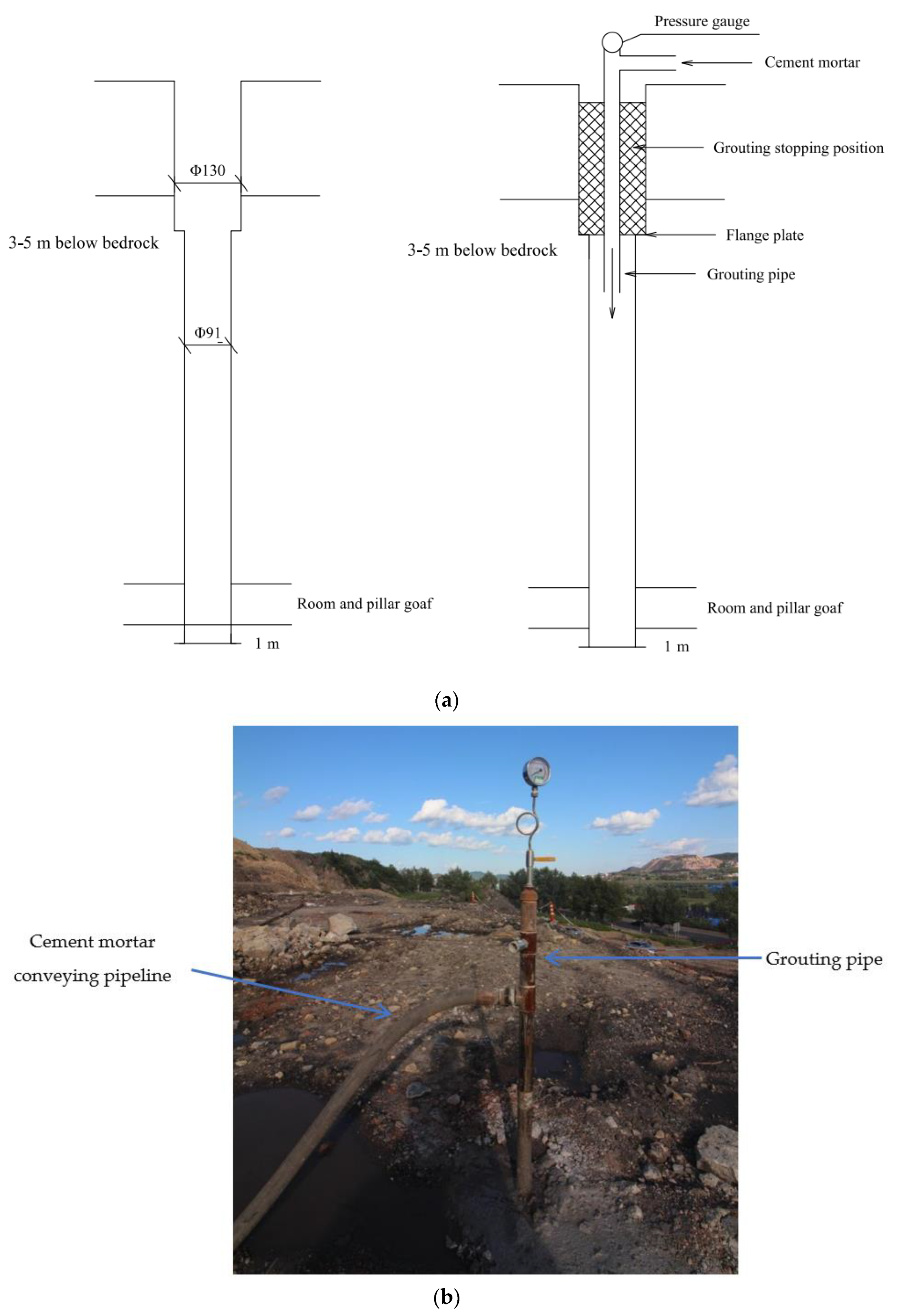
Referring to the analysis process of the treatment methods in K1631 + 985~K1632 + 035, the remaining sections to be treated were analyzed, and the treatment methods for each section are presented in Table 10. As can be observed from Table 10, the K1626 + 400~K1626 + 500, K1627 + 945~K1628 + 433, and K1631 + 985~K1632 + 035 sections need to be treated by grouting because they failed the calculations of the roof or coal pillar strength values. The grouting treatment is presented in Figure 8. However, K1633 + 000~K1633 + 160 and K1627 + 145~K1627 + 423 passed the calculation of the load disturbance depth, so it was only necessary to adopt the method of laying a geogrid on the subgrade for treatment purposes. The geogrid is presented in Figure 9. In one year of operation following these calculations, none of the above-mentioned road sections collapsed.
Table 10.
Analysis of treatment methods for each road section.
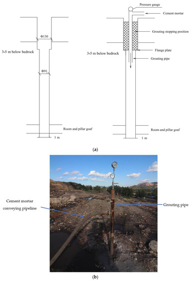
Figure 8.
Grouting treatment. (a) Schematic diagram of grouting (the size of the grouting hole on the left side and the flow direction of slurry on the right side); (b) grouting on site.
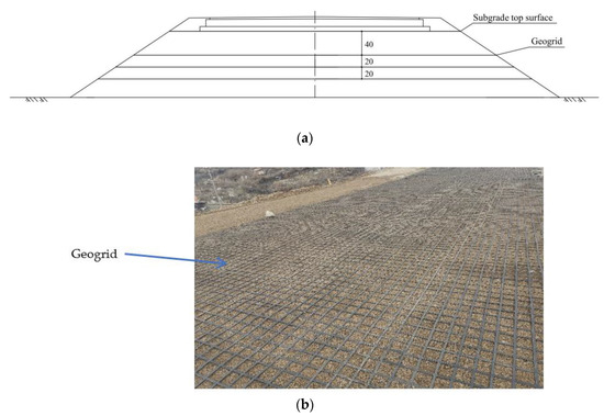
Figure 9.
Geogrid treatment. (a) Schematic diagram of geogrid position; (b) laying geogrid on site.
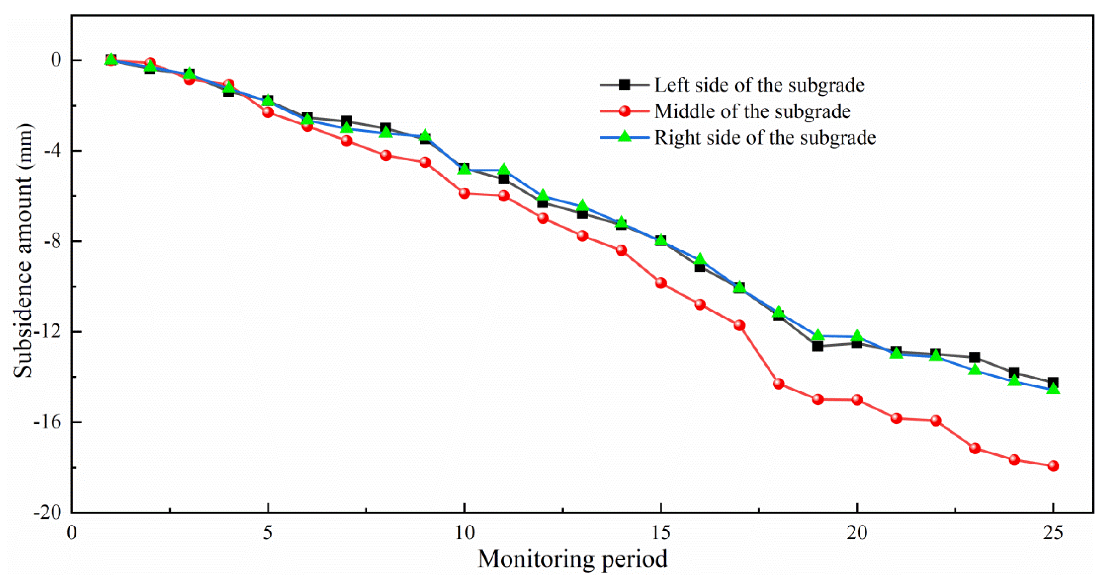
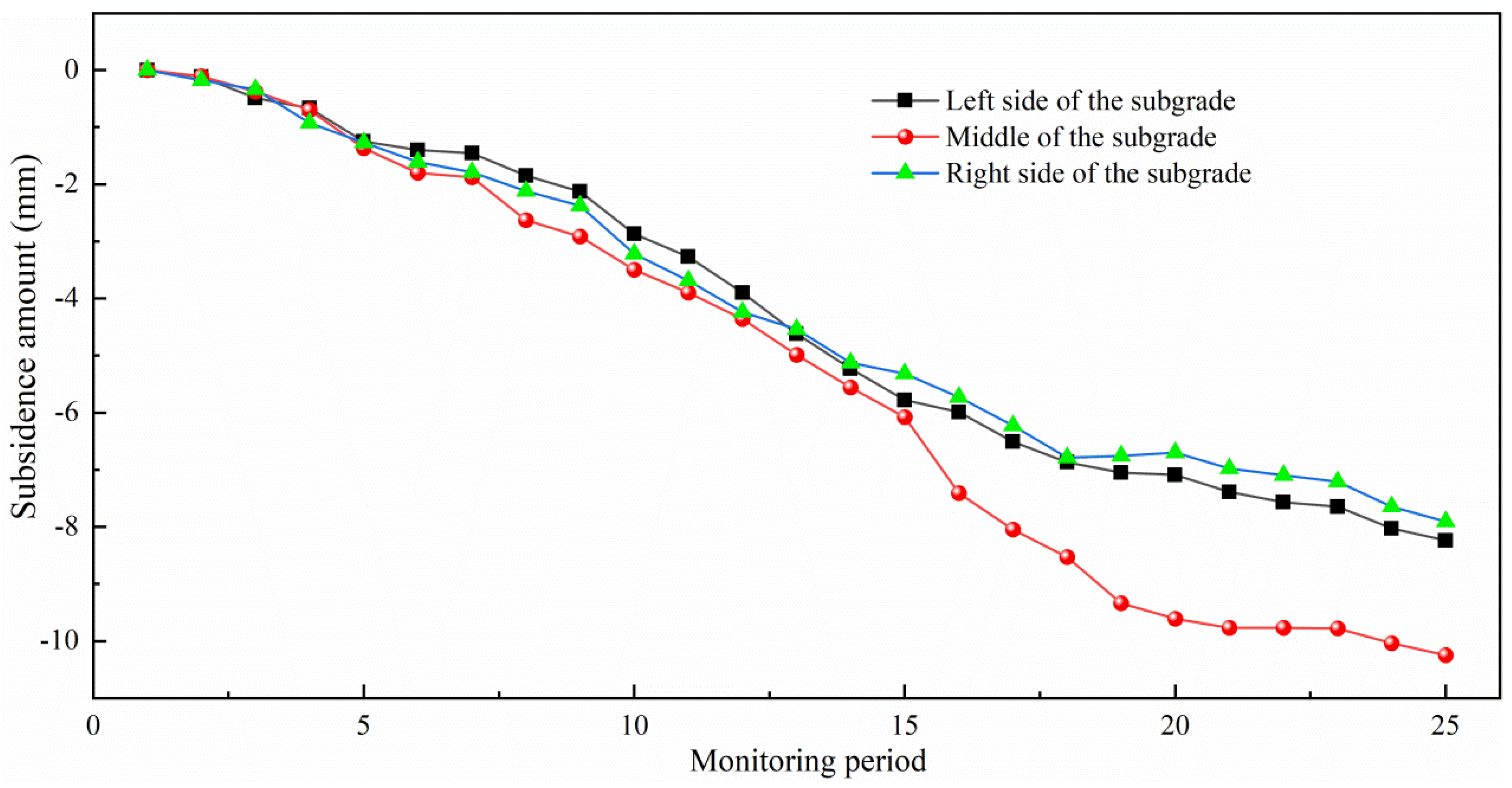
The subsidence of the treated grouting and geogrid sections was monitored by level for one year, once every half month, and a total of 25 periods of subsidence monitoring data were obtained. Taking the K1631 + 985~K1632 + 100 grouting treatment section and the K1627 + 145~K1627 + 423 geogrid-laying treatment section as examples, the treatment effects of the two methods were evaluated. The subsidence of each section is presented in Figure 10 and Figure 11.

Figure 10.
The subsidence of the grouting treatment section (K1631 + 985~K1632 + 100).
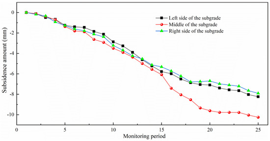
Figure 11.
The subsidence of geogrid treatment section (K1627 + 145~K1627 + 423).
As can be observed in Figure 10, following one year of grouting treatment for K1631 + 985~K1632 + 100, the subsidence trend in the middle and both sides of the subgrade gradually tended to become smooth over time, which is in line with the subsidence trend of the normal subgrade. The values of the middle and both sides of the subgrade were −17.94, −14.25, and −14.57 mm, respectively, which met the subsidence requirements of the subgrade following construction. It can be observed in Figure 11 that the subsidence trend of K1627 + 145~K1627 + 423, at the middle and both sides of the subgrade, gradually tended to become smooth over time after laying the geogrid for one year, which agrees with the subsidence trend of the normal subgrade. The subsidence values of the middle and both sides of the subgrade were −10.25, −8.24, and −7.91 mm, respectively, which met the subsidence requirements of the subgrade following construction.
It can be observed from the above analysis that the post-construction subsidence of the subgrades in the K1631 + 985~K1632 + 100 grouting treatment section and the K1627 + 145~K1627 + 423 geogrid-laying treatment section met the requirements, and the subsidence trend tended to be gentle, with a good treatment effect.
5. Discussion
In this study, the evaluation of the treatment methods for room-and-pillar mining goaf treatments under traffic load conditions was analyzed. The novelty of the research lies in the following areas: firstly, the disturbance depth of the traffic load was coupled, the calculation results were analyzed by multiple linear regression, and the calculation formula for the disturbance depth of the traffic load was fitted. Secondly, according to the relationship between the disturbance depth of the traffic load and the mining depth and the stability of the roof, coal pillar, and base plate, the applicability of the treatment method was analyzed.
The research presented in this study contributes to the research concerning the treatment methods used for goaf areas under highways, as the previous research mostly focused on the treatment method used and did not extensively study the applicability of these methods.
From the multiple regression analysis of the numerical simulation results, it can be observed that, although the disturbance depth of traffic load is related to the pavement elastic modulus, subgrade height, unit weight of foundation soil, vehicle speed and vehicle load, the pavement elastic modulus, subgrade height, vehicle speed, and vehicle load are significant influencing factors, while the unit weight of foundation soil is a non-significant influencing factor. From the evaluation of the treatment method, it can be observed that a disturbance depth of 1.5 times that of the traffic load does not reach the roof depth of the room-and-pillar mining goaf areas and only requires the laying of a geogrid on the subgrade for treatment; grouting is unnecessary. When the disturbance depth of the subgrade load exceeds the roof depth of the room-and-pillar mining goaf areas by 1.5 times, it is necessary to calculate the stability of the roof, coal pillar, and base plate. If they are all in a stable state, the geogrid can be used for treatment purposes; otherwise, grouting treatment must be conducted. From the subsidence monitoring results of the engineering cases, it can be seen that the subsidence values of the goaf areas treated by these two treatment methods, respectively, all met the requirements of the post-construction subsidence, indicating that the evaluation process of the treatment methods can be applied to practical projects.
As mentioned above, the research content of this paper provides a scientific basis for the applicability of room-and-pillar mining goaf treatment methods. It also provides a reference for similar engineering constructions. However, this paper only verified the analysis results through an actual project. In future studies, similar simulation tests can be used to provide more samples to verify the analysis results of this study.
6. Conclusions
Based on the orthogonal simulation experiment, this paper deduced the calculation formula for the disturbance depth of traffic load conditions. By combining this formula with the structural mechanics analysis method, an evaluation process was proposed for the methods of treating a room-and-pillar goaf under a traffic load. The following conclusions were drawn:
- (1)
- The calculation formula of traffic load disturbance depth obtained by a multiple linear regression analysis has a high degree of fitting and can accurately represent the quantitative relationship between the traffic load disturbance depth and the four influencing parameters: vehicle load, vehicle speed, pavement elastic modulus, and subgrade height;
- (2)
- Combined with the disturbance depth of the traffic load, the depth of the goaf, and the stability of the roof, coal pillar, and base plate, this paper proposed an evaluation flow of the room-and-pillar mining goaf treatment method which is simple and easy to use, universally applicable, and not limited to specific projects;
- (3)
- Through the analysis of the goaf area in the Jixi section of the Dan-A national highway, the results show that the K1631 + 985~K1632 + 035, K1626 + 400~K1626 + 500, and K1627 + 945~K1628 + 433 sections need to be treated by grouting, while the K1633 + 000~K1633 + 160 and K1627 + 145~K1627 + 423 sections only need to be treated by laying a geogrid on the subgrade. After the national highway was opened to traffic for one year, the highway section treated according to the evaluation process proposed in this paper was opened, and there were no problems with it collapsing.
Author Contributions
Conceptualization, F.Z., C.H., and C.D.; methodology, F.Z., C.H., C.D., L.X., and Q.P.; software, F.Z., C.H., C.D., L.X., and Q.P.; validation, F.Z. and C.D.; formal analysis, F.Z., C.H., C.D., L.X., and Q.P.; investigation, F.Z., C.H., C.D., L.X., and Q.P.; resources, F.Z., C.H., L.X., and Q.P.; data curation, F.Z. and C.D.; writing—original draft preparation, F.Z. and C.H.; writing—review and editing, F.Z. and C.D.; visualization, F.Z. and C.D.; supervision, C.H.; project administration, C.H.; funding acquisition, F.Z., L.X., and Q.P. All authors have read and agreed to the published version of the manuscript.
Funding
This research was funded by the Science and Technology Project of the Department of Transportation of Heilongjiang Province (20210430).
Institutional Review Board Statement
Not applicable.
Informed Consent Statement
Not applicable.
Data Availability Statement
The data used to support the findings of this study are available from the corresponding author upon request.
Acknowledgments
This work was supported by the Department of Transportation of Heilongjiang Province.
Conflicts of Interest
The authors declare no conflict of interest.
References
- Wen, L.; Li, J. Goafs Hazard Analysis and Control Technology of Room Mining in Shallow Coal Seam. Saf. Coal Mines 2014, 45, 64–66. [Google Scholar] [CrossRef]
- Dang, L.H.; Hong, Y.H.; Bin, Z.; Gang, C.; Ru, X.J.; Jun, X.H.; Hai, K.L. Control study of strong strata behaviors during the fully mechanized working face out of concentrated coal pillar in a shallow depth seam in proximity beneath a room mining goaf. J. China Coal Soc. 2015, 40, 6–11. [Google Scholar]
- Tu, S.H.; Dou, F.J.; Mo, Z.J.; Wang, F.T.; Yuan, Y. Strata control technology of the fully mechanized face in shallow coal seam close to the above room and pillar gob. J. China Coal Soc. 2011, 36, 366–370. [Google Scholar]
- Sun, Q. Influence Factors Analysis of Residual Pillar in Goaf and Its Evaluation Methods. Saf. Coal Mines 2017, 48, 128–131. [Google Scholar] [CrossRef]
- Zhang, J.; Wang, B. Stability of isolated coal pillar and overburden instability in shallow-buried interval gob. J. Min. Saf. Eng. 2020, 37, 936–942. [Google Scholar]
- Zhang, J.; Zhuo, Q.S.; Yang, S.; Yang, T.; Wang, B.; Bai, W.Y.; Wu, J.J.; Xie, S.L. Study on the Coal Pillar Weakening Technology in Close Distance Multi-Coal Seam Goaf. Energies 2022, 15, 6532. [Google Scholar] [CrossRef]
- Zhou, Z.L.; Chen, L.; Zhao, Y.; Zhao, T.B.; Cai, X.; Du, X.M. Experimental and Numerical Investigation on the Bearing and Failure Mechanism of Multiple Pillars Under Overburden. Rock Mech. Rock Eng. 2017, 50, 995–1010. [Google Scholar] [CrossRef]
- Salamon, M.D.G.; Munro, A.H. A study of the strength of coal pillars. J. S. Afr. Inst. Min. Metall. 1967, 68, 466–470. [Google Scholar]
- Li, Y.; Ye, Y.; Liu, X.; Hu, N.; Luo, B.; Yuan, Z. Research on stability of goaf roof under mechanical construction loading. China Saf. Sci. J. CSSJ 2017, 27, 133–138. [Google Scholar]
- Sun, S.; Deng, W.; Liu, W.; Shao, S.; Xiao, J. Roof Thickness of Complex Goaf in Transition from Underground to Open-Pit Mining. Min. Metall. Eng. 2022, 42, 5–8. [Google Scholar]
- Freidin, A.M.; Neverov, S.A.; Neverov, A.A.; Filippov, P.A. Mine stability with application of sublevel caving schemes. J. Min. Sci. 2008, 44, 82–91. [Google Scholar] [CrossRef]
- Ma, H. Coupling Effect of Coal Pillar-Roof And Stability Evaluation of Pillar Goaf; China Mining University: Beijing, China, 2021. [Google Scholar] [CrossRef]
- Yang, Q.; Ding, X.; Wang, X.; Zhang, S. Study on Vertical Earth Pressure Transfer Rule of Loess Subgrade under Vehicle Loading. J. Highw. Transp. Res. Dev. 2021, 38, 40–47. [Google Scholar]
- Liu, J.; Xuezhi, Y.U.; Wencheng, Y.U.; Jing, T.; Zhang, J. Prediction of Extreme Value of Vehicle Loading Using Generalized Extreme Value Distribution. J. Huaqiao Univ. Nat. Sci. 2019, 40, 470–475. [Google Scholar]
- Tang, L.; Chen, H.; Sang, H.; Zhang, S.; Zhang, J. Determination of traffic-load-influenced depths in clayey subsoil based on the shakedown concept. Soil Dyn. Earthq. Eng. 2015, 77, 182–191. [Google Scholar] [CrossRef]
- Levin, F.C.; Back, M.; Vogt, S.; Cudmani, R. Experiment-based estimation of the settlement potential due to dynamic loads from heavy vehicle traffic on the A 44n motorway built on the dump of the Garzweiler opencast mine. Transp. Geotech. 2022, 32, 100674. [Google Scholar] [CrossRef]
- Baotang, S.; Brett, P. Investigation of overburden behaviour for grout injection to control mine subsidence. Int. J. Min. Sci. Technol. 2014, 24, 317–323. [Google Scholar]
- Guo, G.-l.; Feng, W.-k.; Zha, J.-f.; Liu, Y.-x.; Wang, Q. Subsidence control and farmland conservation by solid backfilling mining technology. Trans. Nonferrous Met. Soc. China 2011, 21, S665–S669. [Google Scholar] [CrossRef]
- Jiao, H.; Yang, W.; Shen, H.; Yang, Y.; Liu, J. Study on Multi-Layer Filling Treatment of Extra-Large Goaf and Its Underground Application. Materials 2022, 15, 5680. [Google Scholar] [CrossRef]
- Ao, X.; Wang, X.; Zhu, X.; Zhou, Z.; Zhang, X. Grouting Simulation and Stability Analysis of Coal Mine Goaf Considering Hydromechanical Coupling. J. Comput. Civ. Eng. 2017, 31, 04016069. [Google Scholar] [CrossRef]
- Cai, W.; Chang, Z.; Zhang, D.; Wang, X.; Cao, W.; Zhou, Y. Roof filling control technology and application to mine roadway damage in small pit goaf. Int. J. Min. Sci. Technol. 2019, 29, 477–482. [Google Scholar] [CrossRef]
- D31.03-2011; Technical Rules for Highway Design and Construction in Goaf. People’s Communications Publishing House: Beijing, China, 2011.
- Zhang, Z.; Wang, Y.; Zhang, Z.; Feng, T. Analysis on disturbance to subsidence area by dynamic load of highway. J. Saf. Sci. Technol. 2015, 11, 104–109. [Google Scholar]
- Perez-Acebo, H.; Linares-Unamunzaga, A.; Roji, E.; Gonzalo-Orden, H. IRI Performance Models for Flexible Pavements in Two-Lane Roads until First Maintenance and/or Rehabilitation Work. Coatings 2020, 10, 97. [Google Scholar] [CrossRef]
- Bozkurt, T.S.; Karakas, A.S. Investigation of Asphalt Pavement to Improve Environmental Noise and Water Sustainability. Sustainability 2022, 14, 14901. [Google Scholar] [CrossRef]
- D50-2017; Specifications for Design of Highway Asphalt Pavement. People’s Communications Publishing House: Beijing, China, 2017.
- Perez-Acebo, H.; Gonzalo-Orden, H.; Findley, D.J.; Roji, E. Modeling the international roughness index performance on semi-rigid pavements in single carriageway roads. Constr. Build. Mater. 2021, 272, 121665. [Google Scholar] [CrossRef]
- Huang, X. Subgrade and Pavement Engineering; People’s Communications Publishing House: Beijing, China, 2019; pp. 33–34. [Google Scholar]
- Yang, D. Experimental Design and Analysis; China Agricultural Publishing House: Beijing, China, 2002; p. 171. [Google Scholar]
- Rahn, P.H.; Onak, A. Subsidence—Occurrence, prediction and control. Eng. Geol. 1991, 31, 111–112. [Google Scholar] [CrossRef]
- GB51044-2017; Code for Geotechnical Engineering Investigation in Mined-out Area of Coal Mine. China Planning Press: Beijing, China, 2017; p. 46.
- China Institute of Scientific and Technical Information. Report of Overseas Visit-Ground Buildings in Mined-out Areas of Poland; Scientific and Technical Literature Publishing House: Beijing, China, 1979. [Google Scholar]


Disclaimer/Publisher’s Note: The statements, opinions and data contained in all publications are solely those of the individual author(s) and contributor(s) and not of MDPI and/or the editor(s). MDPI and/or the editor(s) disclaim responsibility for any injury to people or property resulting from any ideas, methods, instructions or products referred to in the content. |
© 2023 by the authors. Licensee MDPI, Basel, Switzerland. This article is an open access article distributed under the terms and conditions of the Creative Commons Attribution (CC BY) license (https://creativecommons.org/licenses/by/4.0/).