Article

Research on Feature Identification and Trajectory Planning of Pavement Cracks

1
School of Information Science and Engineering, Lanzhou University, Chengguan District, Lanzhou 730000, China
2
School of Mechanical and Automative Engineering, Xiamen University of Technology, Jimei District, Xiamen 361021, China
*
Author to whom correspondence should be addressed.
Appl. Sci. 2023, 13(4), 2241; https://doi.org/10.3390/app13042241
Submission received: 30 December 2022 / Revised: 25 January 2023 / Accepted: 7 February 2023 / Published: 9 February 2023

Abstract

:
As the most common method to detect pavement cracks, manual detection has uncontrollable factors such as low efficiency, inconsistent standards and easy to be interfered with by external forces, so it is not suitable for pavement crack detection in today’s intricate traffic network. In order to improve the efficiency of pavement repair and reduce the labor cost of the repair process, this paper proposes an intelligent pavement crack detection and repair algorithm. The algorithm uses image numerical parameters to classify cracks with different geometric features and extracts texture geometric features of various types of cracks based on different filtering strategies. It solves the problem that traditional single filtering algorithms are difficult to extract features according to the different characteristics of the collected image, which leads to the loss of information. Finally, the algorithm establishes a mathematical model for efficient trajectory planning combined with the nozzle size of the crack-repairing machine. In this paper, the robustness and efficiency test of the algorithm is carried out on the pavement image dataset with various types of cracks, and the experiment is carried out on the intelligent pavement crack detection and repair prototype, which verifies the accuracy and reliability of the planned trajectory.

1. Introduction

As a complex of intricate engineering facilities, motor vehicle lanes require constant maintenance and repair to ensure a high-quality and safe traffic environment. Crack detection utilizes the type, length, and severity of cracks to quantify the condition of the pavement, analyze the cause of the deterioration of the road condition, and is the best indicator for assessing whether the road needs preventive maintenance treatment. Carrying out crack detection at the initial stage is conducive to the proper maintenance of the pavement, so as to save a large amount of cost of repairing in the later stage. According to the degree of manual intervention required, crack detection methods can be divided into manual detection, semi-automatic detection and automatic detection [1]. Even though many scholars have proposed automatic crack detection models, manual detection methods are still the most common in practice. Nevertheless, due to the limitation of manpower, there are many unavoidable problems in manual detection methods, which make it difficult to detect the details of cracks consistently. Therefore, in today’s increasingly developed traffic system, manual detection methods are no longer suitable for large-scale road maintenance projects.
In the past decades, the government and scientific research institutions have made great efforts to build an automated pavement crack detection system. Safaei et al. [2] proposed a comprehensive crack extraction algorithm based on local threshold, morphological manipulation and preprocessing to extract the crack image of pavement damage and calculate the crack width. The researchers also used other methods based on autocorrelation screening, such as two-dimensional pavement image crack detection method based on the weighted neighborhood pixel segmentation algorithm, and Gaussian cumulative density function(CDF) as an adaptive threshold to overcome the disadvantage of fixed threshold in noisy environment [3]. Aiming at the problems of low crack image recognition rate and difficult classification, Ouyang et al. [4] proposed a crack recognition method based on image enhancement and image segmentation. Akagic et al. [5] proposed a crack detection method based on the Otsu thresholding method and image segmentation, which does not need to know the morphological characteristics of cracks in advance, but uses the spatial distribution characteristics of crack pixels to analyze the image. Nevertheless, for complex and diverse pavement crack detection work, such traditional detection algorithms based on image segmentation algorithms have problems of low efficiency and poor robustness [6].
Machine learning methods can efficiently and accurately classify images through image spatial distribution, color tone, pixels and other features before specific crack identification, so are more and more frequently used to solve pavement crack detection problems. Othman et al. [1] proposed an improved Otsu-Canny edge detection algorithm, and the crack detection based on the adaptive multi-resolution threshold technology improved the accuracy of crack extraction. Sari et al. [7] proposed a method for identifying cracks in asphalt pavement based on Support Vector Machine and Otsu thresholding method. As an efficient feature extraction technology, Hough transformation is also very helpful to solve the problem of crack identification. By comparing a variety of edge detection, Kaur et al. [8] proposed a crack detection method based on Canny–Prewitt operator and Hough transformation, and proved that the algorithm has the best robustness and efficiency through experiments. Nasser [9] proposed a road trajectory fitting method based on Hough space transformation and the K-means clustering algorithm, which greatly reduces the number of feature points while fitting the trajectory efficiently. Neural network is the core of trainable algorithm for crack detection, which has advantages over threshold-based techniques and morphological tools. Now, many scholars have proposed to train complex neural networks to obtain a model that can accurately identify pavement cracks and fit the trajectory [10,11,12]. However, although these methods could provide extremely fine fitting effect, the main drawback of learning-based approaches is that the build learning step is usually accompanied by a tricky manual labeling step, which does not provide fast and fully automatic analysis compared to image segmentation-based methods [2].
Most crack identification algorithms today have relatively single scene quality requirements for the processed image features. However, affected by objective factors such as light and shooting angle, the crack images identified by the machine inevitably have different contrasts, textures and shades. At present, there is still a lack of a systematic pavement crack detection and trajectory planning algorithm, which can balance high accuracy and fast execution efficiency, and is not limited to the complex manual labeling work of the dataset. In order to solve this problem, this paper proposes an intelligent pavement crack detection and repair algorithm. The algorithm establishes a targeted filtering model for different types of crack feature images, and realizes intelligent trajectory planning based on the Hough space transformation and K-Means clustering algorithm. Through a large number of experiments, we find that under the condition of fixed size, the crack images collected by the camera can be divided into two types according to the morphological characteristics of the main crack and the distribution characteristics of the noise, namely the high-density noise wide crack type and the low-density noise narrow crack type. According to this, the algorithm firstly performs global variance calculation on the binarized original crack image and accurately classifies two typical crack features based on the threshold discrimination method. For the high-density noise wide crack type images which tend to have wide main cracks and dense noise distribution, the algorithm uses the median filter and Otsu thresholding method, which greatly eliminates the image dense noise groups while retaining the main crack feature relatively completely. For the low-density noise narrow crack type images which tend to have narrow main cracks and scattered noise distribution, the algorithm accurately extracts the crack features through the eight-neighborhood maximum connected component extraction algorithm, thus avoiding the loss of narrow crack feature information caused by strong filtering. After crack feature extraction operation, the algorithm uses Hough space transformation and K-Means clustering algorithm to establish a mathematical model that can be combined with the nozzle size of the crack repair model for efficient trajectory planning. Finally, the robustness test of the algorithm is carried out on pavement image dataset containing various types of cracks, and experiments are carried out on the intelligent pavement crack detection and repair prototype to verify the accuracy and reliability of its planned trajectory.

2. Research Significance

This paper aims to propose an intelligent pavement crack detection and repair algorithm, which can establish a targeted filtering model for different types of crack feature images to extract the main crack feature quantity more completely, and establish a mathematical model for efficient trajectory planning based on the crack feature quantity combined with the crack repair model nozzle size.

3. Intelligent Pavement Crack Detection and Repair Algorithm

3.1. Algorithmic Framework

In this paper, an intelligent pavement crack detection and repair algorithm is proposed. The algorithm consists of four parts to realize pavement crack feature identification and trajectory planning, and its framework is shown in Figure 1. First, the algorithm calls the system camera to capture the scene images with a fixed size, and performs a preliminary binarization operation on the images collected by the camera one by one at the system terminal to obtain the binarized crack image. For the binarized scene image, the algorithm adopts the threshold discrimination method, and compares the preset threshold with the global variance of the pixel matrix, and then divides the corresponding original crack image into a high-density noise wide crack type and a low-density noise narrow crack type. The algorithm proposes targeted filtering policies for the two types of graphs, respectively. For the high-density noise wide crack type image, the algorithm extracts the original image again, smoothes the texture features of the original image based on the median filtering method, and uses the Otsu threshold algorithm to eliminate the dense noise group and capture the main crack feature. For the low-density noise narrow crack type image, the algorithm obtains the binarized crack image based on the Otsu thresholding algorithm and uses the eight-neighborhood maximum connected component extraction algorithm to achieve accurate extraction of fine crack features. In the Hough space transformation stage, the algorithm performs Canny edge detection and Hough lines fitting on the feature-extracted image and collects all the endpoints of the fitted feature lines. Finally, according to the complexity of the crack shape, the algorithm uses the K-Means clustering algorithm to divide the fitting feature endpoint set into several clusters, and connects each cluster center in the output stage to form a crack repair trajectory.

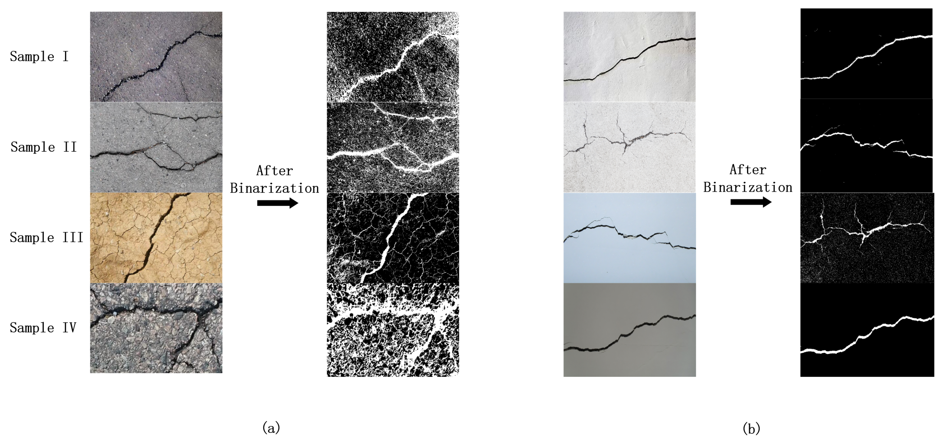
3.2. Image Filtering Stage

In the image filtering stage, the algorithm firstly calls the system camera to take pictures of the cracks and upload them to the system terminal for subsequent analysis. Since the image signal of the camera sensor is easily affected by pulse currents, analog-to-digital converter or bit transmission errors occur, and the crack scene image collected by the camera usually contains a lot of salt and pepper noise. However, the pavement crack repair algorithm based on traditional morphological segmentation methods such as the Otsu thresholding method and histogram equalization method only uses a single mode of filtering method and is difficult to establish a highly adaptive filtering model for different types of crack images. In order to solve this problem, the algorithm divides the original crack images into two categories as shown in Figure 2 according to the distribution of the probability density function and the relative size of the main crack feature. Namely, high-density noise wide crack type image and low-density noise narrow crack type image, and we purpose the targeted filtering policies for these two types of crack images, respectively.

3.2.1. Image Classification Policy Engine

Due to unstable environmental conditions such as light, angle and background tone, the relative size of the main crack feature points and noise points contained in the images collected by the system camera, and the degree of noise dispersion is often uncontrollable, which in turn affects the subsequent image filtering and feature extraction. In 2021, Sheerin er al. [13] conducted an integrated analysis of mainstream crack detection and classification techniques, and proposed the necessary conditions for a pavement crack feature identification algorithm. That is, the morphological characteristics of cracks and noise clusters in different types of scene images should be comprehensively considered, and a targeted filtering model should be established. Accordingly, we experimented with global variance calculation on multiple crack images. Figure 3 shows the comparison of the original binarization effect of the two types images, while Table 1 shows the global variance calculation results of the images. After a large number of experiments, we found that under the condition of fixed size, the image in Figure 3a has relatively narrow cracks and the noise distribution of this type of image after binarized is also relatively scattered, meanwhile, the global variance of the calculated pixel matrix is usually in the range of 0–300 as shown in Table 1. However, the image in Figure 3b has a relatively wide crack and the noise distribution of this type of image after binalization is concentrated on the edge side of the crack. The amount of noise of this type is much larger than that of the narrow crack type image, and the global variance of the calculated pixel matrix is usually greater than 800. Therefore, for a certain size of the crack scene binarized image, the threshold discrimination method is introduced as the image classification policy engine, and 500 is selected as the appropriate classification threshold. According to the difference of the global variance value of the pixel matrix, the image is divided into high-density noise wide crack type and low-density noise narrow crack type, and the corresponding processing strategies are adopted, respectively.

3.2.2. Wide Crack Feature Extraction Policy

In road repair work, high-density noise wide crack type images are a common type of image captured by system cameras. In this type of image, the main crack is often thick, and dense noise points are commonly distributed at both ends, which brings a certain degree of difficulty to the extraction of main crack features. In general, there are the following feature extraction methods for crack scene images: 1. Otsu thresholding method [5]; 2. Image enhancement combined with segmentation methods [7]; 3. Canny operator edge detection [8]; 4. grayscale morphological filter [14]; 5. histogram equalization [15]; 6. median filter [16]. However, the above traditional filtering methods are all based on pixel neighborhood feature values to filter images indiscriminately. Applying it directly to filter this type of image is prone to the situation that the noise group and the feature cannot be separated or the crack feature is damaged during filtering. Therefore, in order to filter the dense noise point groups and retain the main crack feature, the algorithm in this paper combines the median filter and the Otsu thresholding method, and proposes a feature extraction policy for high-density noise wide crack type images.
High density noise wide crack type images have Tamura features with large roughness, small contrast and scattered directions. Compared with its opposite category, the cooccurrence variance of its Gray-level Co-occurrence Matrix is larger, so it is not suitable to directly use traditional morphological segmentation method for filtering [17]. The algorithm in this paper firstly uses the median filter method to smooth the original image texture, neutralizes the image roughness, and greatly reduces the possibility of noise clustering. The median filter replaces each pixel in the image with the median value of the sequence of its eight neighborhoods, so that the surrounding pixels are close to the real value, thereby eliminating isolated noise point. As shown in Figure 4, the algorithm uses a 3 × 3 two-dimensional rectangular sliding window to sort the pixel values in the window to generate a monotonically increasing data sequence. The filtering effect is shown in Figure 5. The median filter can smooth the texture of the original crack image on the basis of retaining the main crack feature to the maximum extent.
After median filtering, the image has already have good contrast and regularity. At this time, the traditional morphological segmentation method can be used to accurately extract the main crack feature. The algorithm uses the Otsu thresholding method to binarize the image. By setting the threshold to maximize the variance between the crack and the background class, a binarized image that only contains crack features is obtained [18]. As shown in Figure 6, the Otsu thresholding method accurately removes all the noise groups in this type of crack image, and retains the main crack feature relatively completely. This paper verifies the reliability of the model by comparing the actual effects of various feature extraction and combination methods, as shown in Figure 7.

3.2.3. Narrow Crack Feature Extraction Policy

Corresponding to the high-density noise wide crack type image, the low-density noise narrow crack type image is another common collected scene image, which has the characteristics of long and narrow main cracks and scattered noise distribution. Nevertheless, compared with wide crack images, the feature size of cracks in this type of image is similar to the size of noise points, and there is a risk of filtering noise points and feature points together by using the same feature extraction policy. Therefore, it is necessary to design a feature extraction policy for this type of image, which can filter the sparsely distributed salt and pepper noise without losing the feature quantity of fine cracks. The algorithm in this paper binarizes the original image by the Otsu thresholding method, and uses the eight-neighborhood maximum connected component extraction algorithm to extract the features of the narrow crack sparse noise type image.
In order to ensure that the feature quantity of the narrow crack would not be affected by the filtering algorithm to the greatest extent, this paper proposes a maximum connected component extraction algorithm based on the pixel features of the eight neighborhoods of the image. Based on the sparse distribution of image noise, the algorithm extracts the largest area connected component to achieve image filtering without feature loss. The algorithm flow is as shown in Figure 8, which could be divided into 5 steps.
(i)
Establish a label matrix of the same size and a one-dimensional array for storing the area size of each connected component according to the pixel matrix of the incoming image.
(ii)
Traverse the pixel points of the binarized image row by row or column by column to obtain their pixel values.
(iii)
If the values of the four adjacent pixels at the upper left of the traversed pixel are not all 0, assign the same label value to the pixel and the adjacent pixels that are not 0, and record the number of consecutive pixels currently traversed. The working principle of the algorithm is shown in Figure 9.
(iv)
Loop through the pixel matrix until the adjacent pixels of the traversed pixels are all 0, treat the pixel set with the same label value as a connected component, store its area in the area array, and update the label value to record the next connected components.
(v)
Traverse the image multiple times until the elements of the label matrix and the area array would no longer change. Retrieve the largest area value in the area array, which corresponding connected component is just the desired crack feature quantity.
The execution result of the algorithm is shown in Figure 10. The algorithm removes the scatteredly distributed noise points in the original image while completely retaining the narrow crack feature.

3.3. Canny Marginalization and Hough Space Transformation

In the image filtering stage, for the high-density noise wide crack type image and the low-density noise narrow crack type image collected by the system camera, the algorithm adopts corresponding feature extraction policies, respectively, and obtains a binarized image containing only crack features. In order to further fit the crack to obtain the coordinate points of the repair trajectory, the algorithm uses the Canny edge detection algorithm to extract the edge of the binarized image, and adopts the polar coordinate Hough space transformation method to perform the Hough straight lines fitting on the feature lines of the edged crack image.
The Hough space transformation, as a very important method for detecting the shape of discontinuous point boundaries, transforms the image coordinate space into the parameter space, and realizes the fitting of straight lines and curves. The algorithm in this paper adopts the generalized polar coordinate Hough space transformation [19], and the algorithm flow is as follows:
a.
The algorithm uses the normal form to represent each line in the image coordinate space: r = x c o s θ + y s i n θ , where r represents the distance from the origin of the coordinate system to the straight line, and θ represents the angle formed by the coordinate point and the x-axis. Therefore, in Hough space, any straight line can be represented by a ( r , θ ) parameter pair and points on the same line have the same ( r , θ ) parameter pair. If many feature points in a parameter space hold the same ( r , θ ) parameter pair, it means that in the Cartesian coordinate system the corresponding number of feature points in are collinear. After this step, each line in the binarized image is represented in the form ( r , θ ) .
b.
For each coordinate point in the parameter space, the algorithm counts the corresponding ( r , θ ) parameter pair in the Hough space, then we could establish an array which contains the count values of all ( r , θ ) parameter pairs.
c.
The algorithm uses a voting mechanism to traverse the ( r , θ ) parameter pairs corresponding to all feature points with non-zero pixel values in the image matrix, and vote for the model parameters. When there are feature points with the same ( r , θ ) , the corresponding parameter pair is increased by one vote. After the execution of this step, we can obtain the global statistics of the parameter pairs, so that the parameter pairs with high statistical times can be set as the contour lines recognized by the Hough space algorithm.
d.
An appropriate threshold is set according to the size of the pixel matrix and the ( r , θ ) parameter pair with a high number of votes is retained, and the corresponding straight line constitute the Hough space fitting line set of the image.
The Hough space transformation uses the global characteristics of the image to connect the edge pixels and form a closed boundary of the region. While directly performing Hough space line fitting on the binarized crack feature image will introduce a lot of unnecessary redundant calculations. In order to achieve the best fitting effect, the algorithm introduces the Canny edge detection algorithm to marginalize the crack feature image in the early stage of Hough line fitting.
The Canny edge detection algorithm is a multi-level edge detection algorithm, which smooths the image through Gaussian filtering, calculates the image intensity gradient, performs non-maximum suppression of the gradient amplitude and double threshold processing to achieve the optimal edge detection of the image [20]. Since in the image filtering stage, the algorithm has performed filtering operations according to different types of crack feature images, the Canny operator introduced in the algorithm would only include the operation of calculating image gradient and non-maximum suppression. The Canny algorithm would firstly introduce the x-direction convolution operator S x and y-direction convolution operator S y as shown in Equation (1), and calculate d y , d x by Equation (2) for each pixel in the image matrix. Then the algorithm would calculate the image gradient magnitude M ( x , y ) according to Equation (3), and finally get the gradient direction angle θ M by Equation (4). The specific mathematical model for calculating the image gradient θ M is shown in Equations (1)–(4), where Equation (1) represents the convolution operators in the x and y directions, respectively, and Equations (2)–(4) represent the process of calculating the image gradient direction angle through the convolution operator.
S x = 1 1 1 1 , S y = 1 1 1 1
d x = f ( x , y ) × S x , d y = f ( x , y ) × S y
M ( x , y ) = d x 2 ( x , y ) + d y 2 ( x , y ) = | d x ( x , y ) | + d y ( x , y ) |
θ M = a r c t a n ( d y d x )
After obtaining the image intensity gradient, the algorithm performs non-maximum suppression on the amplitude along the gradient direction to eliminate the non-edge point set. The specific process is as follows:
i.
Through the image coordinate angle, the edge directions are divided into four directions: vertical, horizontal, 45°, and 135°. The corresponding gradients are also four directions orthogonal to the edge direction.
ii.
For a horizontal edge, its gradient is vertical, and the gradient direction angle satisfies: θ M [ 22.5 ° , 22.5 ° ] [ 157.5 ° , 180 ° ] [ 180 ° , 157.5 ° ] ; for a 135°edge, its gradient is 45°, and the gradient direction angle satisfies: θ M [ 22.5 ° , 67.5 ° ] [ 157.5 ° , 112.5 ° ] ; for a vertical edge, its gradient is in the horizontal direction, and the gradient direction angle satisfies: θ M [ 67.5 ° , 112.5 ° ] [ 112.5 ° , 67.5 ° ] ; while for a 45° edge, its gradient is 135°, and the gradient direction angle satisfies: θ M [ 112.5 ° , 157.5 ° ] [ 67.5 ° , 22.5 ° ] .
iii.
As shown in Figure 11, along the above-mentioned four types of gradient directions, the algorithm compares the value of the traversed pixel with the values of its neighborhood. For each pixel traversed by the algorithm, if its pixel value is the maximum value in the neighborhood centered on it, its pixel value is retained, otherwise, its pixel value is set to 0.
After processing by the Canny edge detection operator, the algorithm uses the Hough space transformation to perform a line fitting operation on the boundary of the image crack feature, and the obtained fitting trajectory is shown in Figure 12.

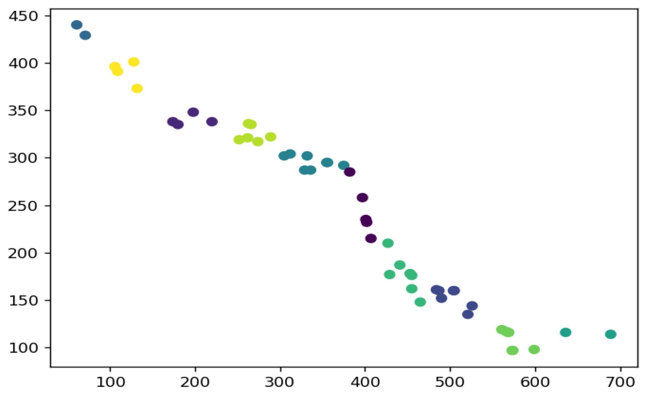
3.4. K-Means Clustering and Fitting Trajectory Output

In real road crack inspection work, the shape of the camera-collected image is often uncertain, resulting in different lengths and widths of crack features. However, the Hough space line fitting algorithm would include all the feature points located inside the crack boundary one by one into the statistical category. For cracks with larger widths, directly using the line set fitted by the algorithm as the coordinates of the repair trajectory is prone to the situation of trajectory redundancy as shown in Figure 12. To solve this problem, this paper proposes a trajectory-fitting method based on the K-Means clustering algorithm, which can significantly reduce the number of trajectory endpoints while efficiently fitting the crack feature.
The K-Means clustering algorithm is a clustering algorithm based on the Euclidean distance of feature endpoints. Its core idea is to determine that the closer the distance between two targets, the greater the similarity. By iterative calculating Equation (5), each point in the endpoint set is divided into corresponding clusters by the algorithm [21], where S represents the set of all cluster center points while S i represents the ith cluster divided by the algorithm, and x represents the coordinates of any feature point located in cluster S i .
a r g S m i n i = 1 k x S i | | x μ | | 2 = a r g S m i n i = 1 k | S i | × V a r S i
The trajectory fitting process based on the K-Means clustering algorithm proposed in this paper is shown in Figure 13.
The K-Means algorithm performs cluster analysis on all trajectory endpoints generated in the Hough space line fitting process, and divides the endpoint set into a corresponding number of clusters according to the morphological complexity of the crack, as shown in Figure 14.
Finally, the algorithm identifies the k cluster centers obtained as the endpoints of the road repair trajectory, and connects them end to end based on the shortest Euclidean distance of the endpoints of the trajectory to obtain the complete fitting trajectory. The fitting results are shown in Figure 15.

4. Experimental Design

4.1. Construction of the Intelligent Pavement Crack Detection and Repair Prototype

In order to verify the efficiency of the algorithm in this paper, a motion control card, servo driver, servo motor, laser sensor, high-definition camera and laptop computer were used to build an intelligent pavement crack detection and repair prototype. As shown in Figure 16, the prototype consists of two parts: a servo motor with three axes and a screw rod with one axis. The activity range of the servo motor is 1500 mm × 400 mm × 500 mm, and each active axis is equipped with three laser ranging sensors with an effective range of 8000 mm and an accuracy of 1 mm, including two limit sensors and one origin sensor. The mechanical parameters of the equipment are shown in Table 2. The prototype is controlled by a four-axis high-precision motion control card, as shown in Figure 17. The x, y, and z axes correspond to the feed axes of the three motion directions of the servo motor, respectively, and the fourth axis screw is used to move the original station of the crack image. The original crack image is placed in the lead screw tray, and the side end of the tray is equipped with a laser sensor. The servo motor can be positioned to the workpiece coordinate system through the laser sensor, and the crack scene image can be identified and captured by the high-definition camera at the front of the motor and uploaded to the model terminal, so as to perform the fitting of the road repair trajectory. The specific equipment parameters of the prototype are shown in Table 3.

4.2. Experimental Results and Analysis

In this paper, the robustness, efficiency and accuracy of the algorithm are comprehensively tested through the terminal algorithm simulation fitting verification and the experimental prototype actual scene verification.

4.2.1. Algorithm Simulation Fitting Verification

In the terminal algorithm simulation fitting verification stage, this paper uses 30 crack sample images captured by the high-definition camera of the prototype during the actual operation for analysis. Each group of experimental samples was collected under different scene conditions such as walls and pavements. The crack lengths, widths, colors and shade depths contained in each image also varies. At the same time, in order to standardize the measurement fitting results, manual ground truth labeling was carried out for all the 30 crack sample images selected. Part of the experimental results is shown in Figure 18. The algorithm can accurately extract and identify trajectories for both types of camera images under light and dark backgrounds.
The crack repair work has high requirements for the recognition accuracy and execution efficiency of the automatic algorithm. Therefore, in order to comprehensively reflect the advancement of the proposed algorithm with the traditional recognition method based on morphological segmentation and the recognition method based on deep learning, the algorithm proposed is compared with the algorithm in the literature [5,12] in terms of recognition accuracy and computational efficiency. The detailed analysis of this stage is as follows.

Algorithm Accuracy Analysis

In order to measure the performance in accuracy between the pavement crack repair trajectory fitted by the algorithm and the real crack feature, the RMSE metric is selected as the evaluation metric of the algorithm fitting effect. By calculating and comparing the RMSE values between the labeled ground truth and the fitted trajectory lines in the sample crack image, the accuracy of each algorithm can be comprehensively analyzed, and the results are shown in Figure 19.

Algorithm Execution Efficiency Analysis

In order to evaluate the performance in execution efficiency between the proposed algorithm and the algorithm in the literature [5,12], this paper takes the above-labeled crack image dataset as the target, and calculates the time cost required by the proposed algorithm and the algorithm in the literature [5,12] to identify crack images with different complexity, respectively, and the results are shown in Figure 20.

Performance Analysis

Through the above performance analysis and comparison results, it can be seen that the proposed algorithm has relatively excellent performance, which proves the advancement of the proposed algorithm. Although the algorithm of literature [12] is slightly better than the algorithm of this literature in terms of accuracy, the time cost of the algorithm in the literature [12] is much higher than that of the proposed algorithm when dealing with the same samples. On the other hand, our proposed algorithm holds a similar execution efficiency with the algorithm of paper [5] while a better fitting accuracy compared to it. In summary, at the cost of a small performance overhead, the proposed algorithm basically meets the requirements of crack repair work, and is more suitable for the actual scene of pavement crack repair work.

4.2.2. Experiment Verification

The built intelligent pavement crack detection and repair prototype is used to verify the fitting effect of the algorithm in this paper in practical application scenarios. After completing the camera calibration and establishing the workpiece coordinate system, a crack scene image would be placed on the screw tray of the prototype, and the crack image would be captured by the front-end camera of the servo motor and uploaded to the model terminal. After algorithm processing, the servo motor receives the coordinate points of the feedback crack repair trajectory and is controlled by the motion control card to drive a fixed 2mm gray marker to draw a fitting trajectory in the scene image to simulate the real crack repair work. Finally, this paper evaluates the accuracy of the algorithm by analyzing the radial distance error between the trajectory points drawn by the servo motor and the real crack feature points during the operation of the prototype.
As shown in Figure 21, the fitted trajectory drawn by the servo motor is highly coincident with the feature of the scene crack image. In order to compare the accuracy of the algorithm fitting horizontally, this paper selects 7 cluster centers generated during the K-Means clustering process as the fitting trajectory endpoints for each experiment and uses the orthogonal distance to the original crack feature as the evaluation metric for the accuracy of the fitted trajectory. Table 4 summarizes the radial errors between the fitting track points of the five images used in the experiment and the real crack feature. The calculation method of the radial error is as follows: with the clustering feature points generated by the algorithm as the center of the circle, a circle is made which is tangent to the actual repair trajectory marked in the binarized crack image (the actual repair trajectory is the ground truth pre-marked in the robustness test of the algorithm), and the radius of the circle is the radial error between the fitting point and the feature point of the actual repair trajectory. It can be seen from the table that almost all the errors between the fitted 7 feature endpoints and the original crack feature are less than the radial range of 2 mm, while the nozzle diameter of the pavement repair prototype is within the range of 2–10 mm, which further reflects the accuracy and stability of the algorithm in this paper in the actual model application.

5. Conclusions

To deal with the dilemma of the balance between the high accuracy and the execution efficiency of the crack detection algorithm, this paper proposes an intelligent pavement crack detection and repair algorithm based on the morphological characteristics of image cracks and noise. The algorithm uses the global variance of the pixel matrix as the policy engine, adopts targeted processing policies for different types of crack images, and efficiently generates high-precision fitting trajectories. The main contributions of this paper to the research on crack detection, regarding the proposed method, are as follows: (1) Firstly, the crack images collected under different environmental conditions are effectively classified, and feature extraction strategies are proposed for each type of crack image, which greatly reduces the amount of data and necessary calculation; (2) For high-density noise wide crack type image, median filter and Otsu algorithm are combined to solve the problem that the high-density noise group and the main crack feature can not be separated by using Otsu algorithm alone, and the crack detection accuracy is improved; (3) For the low-density noise narrow crack type image, an eight-neighborhood maximum connected component extraction algorithm is proposed, which can effectively remove all the sparse distribution noise and realize the lossless extraction of the main crack feature; (4) In the trajectory fitting stage, the Hough space transformation is combined with the K-Means clustering algorithm, which greatly eliminated the generation of redundant trajectories and improved the execution efficiency of the algorithm. Finally, through the simulation and fitting verification of the terminal algorithm and the actual scene verification of the experimental prototype, the robustness, efficiency and accuracy of the algorithm are comprehensively tested. In the future, a crack trajectory fitting algorithm that is more efficient and more suitable for real road repair application scenarios will be designed and implemented for complex network crack images and diversified noise backgrounds.

Author Contributions

Methodology, Z.Z.; Formal analysis, Z.Z.; Writing—original draft, Z.Z.; Writing—review & editing, S.C.; Funding acquisition, B.L. and J.L. All authors have read and agreed to the published version of the manuscript.

Funding

This research was funded by the National Natural Science Foundation of Fujian Province (No. 2020J01274) and Xiamen University of Technology Introduced (trained) High-Level Talents Scientific Research Start-up Project.(No. YKJ19020R).

Institutional Review Board Statement

Not applicable.

Informed Consent Statement

Not applicable.

Conflicts of Interest

The authors declare no conflict of interest.

References

  1. Othman, Z.; Abdullah, A.; Kasmin, F.; Ahmad, S.S.S. Road crack detection using adaptive multi resolution thresholding techniques. TELKOMNIKA (Telecommun. Comput. Electron. Control) 2019, 17, 1874–1881. [Google Scholar]
  2. Safaei, N.; Smadi, O.; Masoud, A.; Safaei, B. An Automatic Image Processing Algorithm Based on Crack Pixel Density for Pavement Crack Detection and Classification. Int. J. Pavement Res. Technol. 2021, 15, 159–172. [Google Scholar] [CrossRef]
  3. Safaei, N.; Smadi, O.; Safaei, B.; Masoud, A. Efficient Road Crack Detection Based on an Adaptive Pixel-Level Segmentation Algorithm. Transp. Res. Rec. 2021, 2675, 370–381. [Google Scholar] [CrossRef]
  4. Ouyang, A.; Luo, C.; Zhou, C. Surface Distresses Detection of Pavement Based on Digital Image Processing. In Proceedings of the Computer and Computing Technologies in Agriculture IV: 4th IFIP TC 12 Conference, CCTA 2010, Nanchang, China, 22–25 October 2010. [Google Scholar]
  5. Akagic, A.; Buza, E.; Omanovic, S.; Karabegović, A. Pavement crack detection using Otsu thresholding for image segmentation. In Proceedings of the 2018 41st International Convention on Information and Communication Technology, Electronics and Microelectronics (MIPRO), Opatija, Croatia, 21–25 May 2018; pp. 1092–1097. [Google Scholar]
  6. Koch, C.; Georgieva, K.; Kasireddy, V.; Akinci, B.; Fieguth, P.W. A review on computer vision based defect detection and condition assessment of concrete and asphalt civil infrastructure. Adv. Eng. Inform. 2015, 29, 196–210. [Google Scholar]
  7. Sari, Y.; Prakoso, P.B.; Baskara, A.R. Road Crack Detection using Support Vector Machine (SVM) and OTSU Algorithm. In Proceedings of the 2019 6th International Conference on Electric Vehicular Technology (ICEVT), Bali, Indonesia, 18–21 November 2019; pp. 349–354. [Google Scholar]
  8. Kaur, E.H. Crack Detection and Parameter Estimation on Road Images Using Canny-Prewitt Operator and Hough Transformation. Int. J. Res. Appl. Sci. Eng. Technol. 2017, 5, 1300–1309. [Google Scholar]
  9. Nasser, M. Automatic Road Digitizing of Segmented Aerial Images for Urban Areas Based on K-means and Hough Transformation. In Proceedings of the 2018 International Conference on Computer, Control, Electrical, and Electronics Engineering (ICCCEEE), Khartoum, Sudan, 12–14 August 2018; pp. 1–4. [Google Scholar]
  10. Zhang, K.; Zhang, Y.; Cheng, H.D. CrackGAN: Pavement Crack Detection Using Partially Accurate Ground Truths Based on Generative Adversarial Learning. IEEE Trans. Intell. Transp. Syst. 2020, 22, 1306–1319. [Google Scholar]
  11. Yang, F.; Zhang, L.; Yu, S.; Prokhorov, D.V.; Mei, X.; Ling, H. Feature Pyramid and Hierarchical Boosting Network for Pavement Crack Detection. IEEE Trans. Intell. Transp. Syst. 2019, 21, 1525–1535. [Google Scholar]
  12. Kim, B.; Yuvaraj, N.; Preethaa, K.R.S.; Pandian, R.A. Surface crack detection using deep learning with shallow CNN architecture for enhanced computation. Neural Comput. Appl. 2021, 33, 9289–9305. [Google Scholar] [CrossRef]
  13. Sheerin Sitara, N.; Kavitha, S.; Raghuraman, G. Review and Analysis of Crack Detection and Classification Techniques based on Crack Types. Int. J. Appl. Eng. Res. 2021, 13, 6056–6062. [Google Scholar]
  14. Hou, H.; Lin, W. A New Approach for the Detection of Concrete Cracks Based on Adaptive Morphological Filtering. In Fuzzy Systems and Data Mining VI; IOS Press: Amsterdam, The Netherlands, 2020. [Google Scholar]
  15. Han, H.; Deng, H.; Dong, Q.; Gu, X.; Zhang, T.; Wang, Y. An Advanced Otsu Method Integrated with Edge Detection and Decision Tree for Crack Detection in Highway Transportation Infrastructure. Adv. Mater. Sci. Eng. 2021, 12. [Google Scholar] [CrossRef]
  16. Ukpe, K.C.; Kabari, L.G. Digitized Paintings For Crack Detection Furthermore, Restoration Using Median Filter Furthermore, Threshold Algorithm. Int. J. Hum. Comput. Stud. 2021, 3, 13–19. [Google Scholar]
  17. Iswanto, B.H.; Alma; Sugihartono, I. Feature Extraction of Tea Leaf Images using Dual-Tree Complex Wavelet Transform and Gray Level Co-occurrence Matrix. In Journal of Physics: Conference Series; IOP Publishing: Bristol, UK, 2021; p. 012092. [Google Scholar]
  18. Chen, X.; Li, J.; Huang, S.; Cui, H.; Liu, P.; Sun, Q. An Automatic Concrete Crack-Detection Method Fusing Point Clouds and Images Based on Improved Otsu’s Algorithm. Sensors 2021, 21, 1581. [Google Scholar] [CrossRef] [PubMed]
  19. Cheng, L.; Dong Fang, J.; Wu, Y.; Kang, K. Research on improved image edge detection based on Hough transform. In Proceedings of the International Conference on Image Processing and Intelligent Control (IPIC 2021), Lanzhou, China, 30 July–1 August 2021. [Google Scholar]
  20. Sekehravani, E.A.; Babulak, E.; Masoodi, M. Implementing canny edge detection algorithm for noisy image. Bull. Electr. Eng. Inform. 2020, 9, 1404–1410. [Google Scholar]
  21. Kullarkar, S.P.; Jain, S.V. A Hybrid Approach for Detection and Removal of Raindrops Using kmeans Clustering and Hough Transformation. HELIX 2018, 8, 4056–4060. [Google Scholar]
Figure 1. Algorithm Framework.
Applsci 13 02241 g001
Figure 2. Camera image classification based on targeted filtering policies.
Applsci 13 02241 g002
Figure 3. Comparison of the original binarization effect. (a) indicates the effect for wide crack type, (b) indicates which for narrow crack type.
Applsci 13 02241 g003
Figure 4. Median filtering sliding window.
Applsci 13 02241 g004
Figure 5. Comparison of median filtering.
Applsci 13 02241 g005
Figure 6. Otsu thresholding method processing results.
Applsci 13 02241 g006
Figure 7. Feature extraction effect comparison.
Applsci 13 02241 g007
Figure 8. Flowchart of the eight-neighborhood maximum connected component extraction algorithm.
Applsci 13 02241 g008
Figure 9. Principle of connected component labeling.
Applsci 13 02241 g009
Figure 10. Narrow crack filtering results.
Applsci 13 02241 g010
Figure 11. Schematic diagram of non-maximum suppression.
Applsci 13 02241 g011
Figure 12. Canny operator & Hough line fitting results.
Applsci 13 02241 g012
Figure 13. K-Means clustering algorithm flow.
Applsci 13 02241 g013
Figure 14. Cluster crack feature endpoint collection.
Applsci 13 02241 g014
Figure 15. Algorithm fitting results.
Applsci 13 02241 g015
Figure 16. Prototype design drawing.
Applsci 13 02241 g016
Figure 17. Intelligent pavement crack detection and repair prototype.
Applsci 13 02241 g017
Figure 18. Dataset fitting results.
Applsci 13 02241 g018
Figure 19. Algorithms accuracy comparison results.
Applsci 13 02241 g019
Figure 20. Algorithms execution efficiency comparison results.
Applsci 13 02241 g020
Figure 21. Prototype crack fitting experiment results.
Applsci 13 02241 g021
Table 1. Global Variance Calculation Results.
High Density Noise Wide Crack TypeLow Density Noise Narrow Crack Type
SampleSample ISample IISample IIISample IVSample ISample IISample IIISample IV
Global Variance Value898.5224947.9831806.37601124.1458129.5714116.9045287.2469221.6327
Table 2. Prototype Mechanical Parameters.
ParametersDescription
Sensor TypeBL-100NZ-485
X-axis Origin Sensor Location250 mm (from the left limit sensor)
Y-axis Travel Range150 mm (from the left limit sensor)
Z-axis Travel Range50 mm (from the left limit sensor)
W-axis Travel Range250 mm (from the left limit sensor)
Laser-type635 nm
Sensor measurement accuracy1 mm
Pulse volume of servo motor1412.7 (pulse volume/ms)
Table 3. Prototype equipment parameter.
EquipmentModel
Four-axis motion control cardGoogoltech GT2-400-ACC2-VB-G-A
High-definition cameraHikvision B12- V2-I(POE)
Servo driverDelta-China ASDA-B2-0721-B 750W
Table 4. Radial error of fitted trajectory points.
Crack ImageType 1
(mm)
Type 1
(mm)
Type 1
(mm)
Type 1
(mm)
Type 1
(mm)
Type 1
(mm)
Type 1
(mm)
Average Error
(mm)
Accuracy
Crack Type 11.6241.8580.8551.8252.6011.7241.0231.644100%
Crack Type 11.5301.9420.8741.0051.4290.7430.9621.21285.8%
Crack Type 11.2111.0470.7530.9691.9531.2770.8571.152100%
Crack Type 10.7420.2491.1050.7910.4120.3630.6930.622100%
Crack Type 10.6531.6731.6922.0521.5590.9010.6121.30685.8%
Disclaimer/Publisher’s Note: The statements, opinions and data contained in all publications are solely those of the individual author(s) and contributor(s) and not of MDPI and/or the editor(s). MDPI and/or the editor(s) disclaim responsibility for any injury to people or property resulting from any ideas, methods, instructions or products referred to in the content.

