Article

Mask–Mediator–Wrapper: A Revised Mediator–Wrapper Architecture for Heterogeneous Data Source Integration

Department of Applied Computing, Faculty of Electrical Engineering and Computing, University of Zagreb, Unska 3, 10000 Zagreb, Croatia
*
Author to whom correspondence should be addressed.
Appl. Sci. 2023, 13(4), 2471; https://doi.org/10.3390/app13042471
Submission received: 12 January 2023 / Revised: 10 February 2023 / Accepted: 13 February 2023 / Published: 14 February 2023
(This article belongs to the Section Computing and Artificial Intelligence)

Abstract

:
This paper deals with the mediator–wrapper architecture and observes it in more modern aspects by relating it to architectural quanta. It is an important architectural pattern that enables a more flexible and modular architecture in opposition to monolithic architectures for data source integration systems. This paper identifies certain realistic and concrete scenarios where the mediator–wrapper architecture underperforms. These issues are addressed with the extension of the architecture via the mask component type. The mask component is detailed so it can be reasoned about without prescribing a concrete programming language or paradigm but still providing a working principle. The benefits of the new mask–mediator–wrapper architecture are analytically proven in relevant scenarios. The proof includes a software shift–cost analysis whose results quantitatively show the improvement of the mask–mediator–wrapper architecture over other mediator–wrapper architecture settings. One of the applications of the new architecture is envisioned for modern data sources integration systems backing big data processing.

1. Introduction

Research of data integration has been active for a very long time and remains ongoing to this day. It is not surprising that data integration has been examined from a multitude of angles. It started with simple ideas of monolithic multi-database systems, then evolved following the popularity of federated systems [1]. The trail continued into architecture-based research with the mediator–wrapper (MW) architecture, which brought some concrete systems into existence [2,3,4]. At that point, the idea of NoSQL (not only SQL) systems [5] started to appear. As data were no longer just being stored in relational databases but also in schemaless formats in specialized database management systems and even files, the research community started to express data integration more in terms of data sources.
Data exchange/interchange between data sources was also presented as an idea later on [6]. In parallel, ETL (extract–transform–load) processes [7] over multiple data sources for data warehousing also appeared and are to this day an active research topic [8,9].
Research has currently been exploring the idea of data lakes and how to process such large quantities of distributed, unstructured, and heterogeneous data [10,11]. The research landscape is also currently shifting toward graph-formatted data [12,13,14,15] and data acquired from the Web [16,17,18].
It is clear that the research of data integration is very unlikely to abate, especially as new kinds of potential data sources continue to be created [16,19,20,21,22,23]. The research has yet to produce a concrete, freely usable and open-ended data source integration system. In the words of Golshan et al. [24]:
“…it is time for data integration operators to break free of end-to-end data integration systems and be available in the open source to speed up adoption and progress.”
“The first challenge […] is that progress of data integration and its application in practice are hindered by the fact that there are very few quality tools with which practitioners and researchers can freely experiment.”
Looking at the research’s history in its entirety, it can be assessed that at a certain point, researchers took a well-meaning detour to incorporate more novel systems into the field, forsaking the essentials of tooling that Golshan et al. [24] mentioned. It can be observed that the last large enterprise-wide tools for data source integration were created following the MW architecture [2,4], and that this is a good restarting point.
Of course, the scientific landscape has greatly changed since the 1990s. Today, there is also a shift in discussion about the way in which views are created, or how data sources are represented. With reintroducing the MW architecture, great care is taken to conform it to modern and future requirements, making it the conduit for future scientific work regarding data. It is important to note that the MW architecture already conforms to the modern view of architectures as consisting of architectural quanta [25]. This makes it clear that the MW architecture is not a deprecated idea, but one that has been neglected by the scientific community.
This paper is focused on the MW architecture for data source integration systems and some of its deficiencies. These deficiencies will be presented through the translation of different types of schemas in the system and how the allocation of these schemas affects the responsibilities of certain types of system components. This will show that some components have additional responsibilities, intruding on a flexible and scalable architectural design and making the system difficult to maintain and administrate. This paper then offers a solution to this quandary and presents the need for an additional component in the MW architecture, which will allow for flexible and scalable system componentization in terms of deployment and component management to ease real-world use. Consequently, this paper introduces the mask component as an additional component to the existing component types. This addition prompts us to introduce an extended architectural pattern based on the MW architecture—the mask–mediator–wrapper (MMW) architecture.
This paper is divided into sections by key points of our research. Section 2 covers the methodology used in this research. Section 3 gives an exposition about the ideas and concepts behind the existing MW architecture covered by key authors, as well as solutions implemented in the MW architecture. Section 3.1 and Section 3.2 cover component rules and the concept of a schema hierarchy. Section 4 presents problems of the existing MW architecture. Section 5 covers the contribution of extending the MW architecture with the mask component type. Section 5.2 also contributes by reasoning about the inner components of a hypothetical mask implementation. Section 5.3 contributes with a proof by a quantitative software shift–cost analysis that the MMW architecture is an improvement over the existing MW architecture. Section 5.4 contributes with a hypothetical implementation example that emulates an existing data management system and a discussion on how the MMW allows the system to be extended.

2. Research Methodology

Through research of state-of-the art papers, we found that there is a need for varied data representation in data management systems. We found that existing or previous data source integration systems had not taken this into account, usually represented data in a singular form, and were designed primarily with data integration in mind. This is our primary research problem. Furthermore, comprehensive and accessible data integration systems are a rarity, so we decided to set our research in the direction that would enable us to plan for a future system implementation.
Our research involved finding the most suitable data source integration architecture that can be used in a modern technological setting, and finding a way to extend it to enable flexible and scalable data representation. The choice of the MW architecture consequently allowed us to further discuss the problem through component rules and schema hierarchies, and allowed us to propose the extension as an architectural component. The responsibilities of the proposed component were elaborated through component rules and functional requirements.
Component rules and schema hierarchies gave us an opportunity to qualitatively analyze the extended architecture. To support our claims of improved system management and scalability, we ran the existing and proposed architecture through a thought experiment on an example schema hierarchy.
To quantitatively prove that the proposed architecture is an improvement over the MW architecture in terms of software flexibility, we used a quantitative software shift–cost analysis. The shift–cost analysis was performed through four scenarios that are expected to arise during the use of a data integration system.
To prove that the proposed component’s implementation is feasible, we detailed the proposed component through a conceptual model of functional components devised from functional requirements, a dataflow diagram, and a conceptual component model. We refrained from naming any concrete implementation technology, so it would not interfere with the conceptual design itself. Communication protocols between components are considered as an implementation detail. They are never discussed at length in the core source material. In a concrete implementation, a custom protocol over the transmission control protocol (TCP), hypertext transfer protocol (HTTP), message queue, or data stream could be used. We do not take this into account since we observe the architecture at the component level. An inner component would concern itself with the communication protocol.
To illustrate the proposed architecture’s hypothetical real-world use, we emulated a recently proposed data management system in a case study. The case study shows that the proposed architecture can emulate another system and build on it by allowing additional functionality.

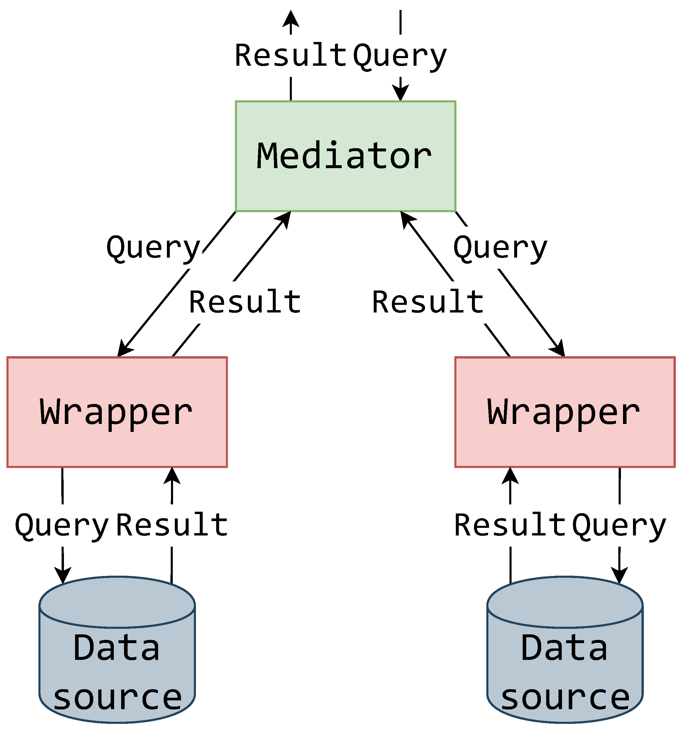
3. The Mediator–Wrapper Architecture

The MW architecture was first envisioned as an information system architecture [26], allowing a modular architecture for subtasking when numerous data sources are imposed, in opposition to monolithic architectures. This was specifically intended for information and knowledge management systems for informed decision making.
Expanding on the idea of what is achievable using the MW architecture, Papakonstantinou et al. [6] observed its usage for the exchange of data across heterogeneous information sources. Roth and Schwarz [3] also observed the mediator–wrapper architecture to uniformly access legacy stores through the GARLIC system [2]. Similarly, the mediator–wrapper architecture was used as a basis for the TSIMMIS project [4]. Garcia-Molina et al. [27] put the mediator–wrapper architecture firmly into the context of data source integration systems.
The MW architecture in the most general sense is an architectural pattern, consisting of mediator and wrapper components, used to query and acquire data from multiple data sources.
The wrapper component is directly connected to a data source and acts as a standardized interface to that data source. The wrapper wraps (or encapsulates) the data source for further use throughout the rest of the system, effectively making it the only component in direct contact with the data source. To ensure such functionalities, the wrapper must be able to translate queries, data and metadata coming to and from the data source, as well as the layers above.
The mediator component is architecturally situated above the wrappers. The mediator’s task is to connect multiple wrappers and integrate their data and metadata. Because data, metadata and queries are logically intertwined, the mediator also must have the ability decompose and allocate queries to its connected wrappers.
Certain aspects of the MW architecture can be clarified by following the top-to-bottom flow of data as shown in the conceptual illustration of the MW pattern in Figure 1. The mediator receives a query which is then propagated accordingly to its connected wrappers. Not all wrappers need be included in a query, as all the data required by the query might not be in all the data sources. The queried wrappers then translate the queries according to their data source’s schema and querying language. The returned result is then translated back into the system standardized result format and propagated to the mediator and above.
This pattern of interaction is the basis for the complete MW architecture. A more global view is shown in Figure 2, illustrating the layering of mediator and wrapper components. The data sources to be integrated are at the lowest layer. Each data source is covered by a single wrapper via a direct connection. As an example, a system where each wrapper operates over a single data source is displayed (Figure 2), although Özsu and Valduriez [28] display a possibility of a wrapper operating over multiple data sources. It can be observed that the “one wrapper—one data source” setting gives more agility for appending new data sources to the integration system, as it allocates the responsibility of overseeing data sources to each wrapper separately and thus balances the workload. It is also interesting to comment that this component setting is better suited for systems being built bottom-up [28,29], where data sources are expected to be appended and the global data overview is expected to change.
The first layer of mediators is located directly above the wrapper layer. Figure 2 displays their relationship in a form where each mediator in this layer can be connected to multiple wrappers, and multiple wrappers can be connected to a single mediator. This is in line with the MW architecture displayed in [28]. Papakonstantinou et al. [6] and Jurczyk et al. [30] displayed an architecture in which each mediator of the first mediator layer is connected to just one wrapper and vice versa, showing that this is also a feasible solution in cases where mediators are only needed for translation. The first mediator layer can be used to mediate between wrappers over paradigmatically similar data sources or data sources that have an overlapping or connected domain.
The second and upper layers of mediators can be used to raise the level of abstraction. The mediators of the upper layers are used to mediate between mediators of the lower layers, thus possibly encompassing multiple different data sources. Such a layering strategy is used by [31] in a form of special and central mediators to organize and distribute processing load, which can also be a beneficial effect if components are run on different machines. On the other hand, Chawathe et al. [4] used layering to enable localized logical management of data sources. This layering strategy was also proposed by [28].
There are also proposed and implemented systems with one monolithic mediator [3,32,33,34,35,36]. This can be found to be an ample, quick, and expedient solution if the number of connected data sources is not large or expected to rise. If the number of connected data sources rises, then the processing load on that single mediator is increased and this can easily lead to increased latency when querying any of the connected data sources through the integration system. These types of systems can be covariantly classified as multidatabase integration systems [37], taking note that the data source component translation is distributed (assigned to the wrappers). It should also be noted that in these cases, the mediator component is not really a component but rather a software module.
Recently, Ref. [38] also focused on creating and maintaining a concern-oriented architecture system. Their workers each have a Data Source API in similarity with wrappers. The mediator’s functionalities are assigned to a single coordinator acting as the query entry point and planner, and another worker to join the query results (akin to a reducer node in MapReduce).

3.1. On the Roles of Mediator–Wrapper Components

Considering the previously mentioned roles and interactions of wrappers and mediators in the MW architecture, it can be determined what kind of properties these components should have, or to which rules they should adhere. In a general sense, any system component should satisfy the following conditions [39]:
  • It can be used by other software elements, its “clients”.
  • It possesses an official usage description, which is sufficient for a client author to use it.
  • It is not tied to any fixed set of clients.
This set of conditions can be expanded to determine what conditions a wrapper or mediator should specifically meet. For wrappers in a data source integration system, by following the example of [2,3] (in their case the GARLIC system), the following rules (goals) are set:
RW1 
The start-up cost to write a specific wrapper should be small. The wrapper itself can be constructed quickly with little need for prior knowledge of the data source integration system internal structure. There is a basic service upon which a specific wrapper is built upon.
RW2 
Wrappers should be able to evolve. Incremental upgrades to the wrapper should be possible.
RW3 
Wrappers should be modular and independent. Wrappers for new data sources can be integrated into the existing data source integration system without disturbing user applications, and other wrappers or components.
RW4 
Wrappers should be participants in query planning. The wrapper may use whatever knowledge it has about a repository’s query and specialized search facilities to dynamically determine how much of a query the repository is capable of handling.
The wrapper component type is succinctly defined in Definition 1.
Definition 1.
The wrapper is a component that allows uniform access to a data source by wrapping the data source in terms of schema, queries, and data.
For mediators in a data source integration system, following the ideas of Wiederhold [26], the following rules are set:
RMe1 
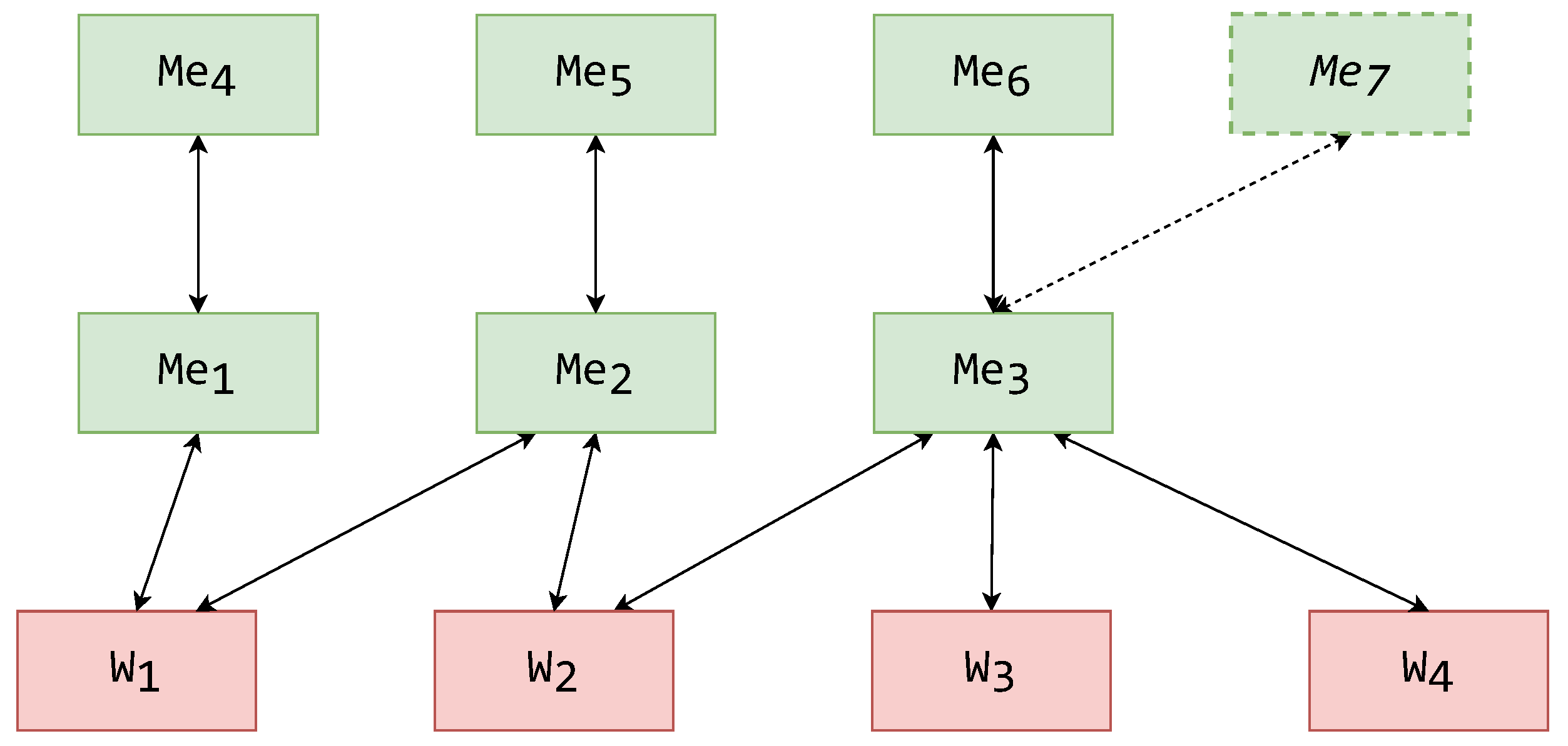
Structuring mediators into hierarchies should not lead to problems.
RMe2 
Mediators should drive transformations. Mediators are there to accommodate the need for data and metadata restructuring. Queries are also affected by this restructuring.
The mediator component type is succinctly defined in Definition 2.
Definition 2.
The mediator is a component used to manage transformations involving multiple unified schemas, the data they represent, and queries used to acquire the data.
The rules for mediators and wrappers imply that they are each architectural quanta. An architectural quantum is defined by Ford et al. [25] as an independently deployable component with high functional cohesion. This surprising compatibility with modern architectural ideas is the main reason why we consider the MW architecture a relevant research topic even today.

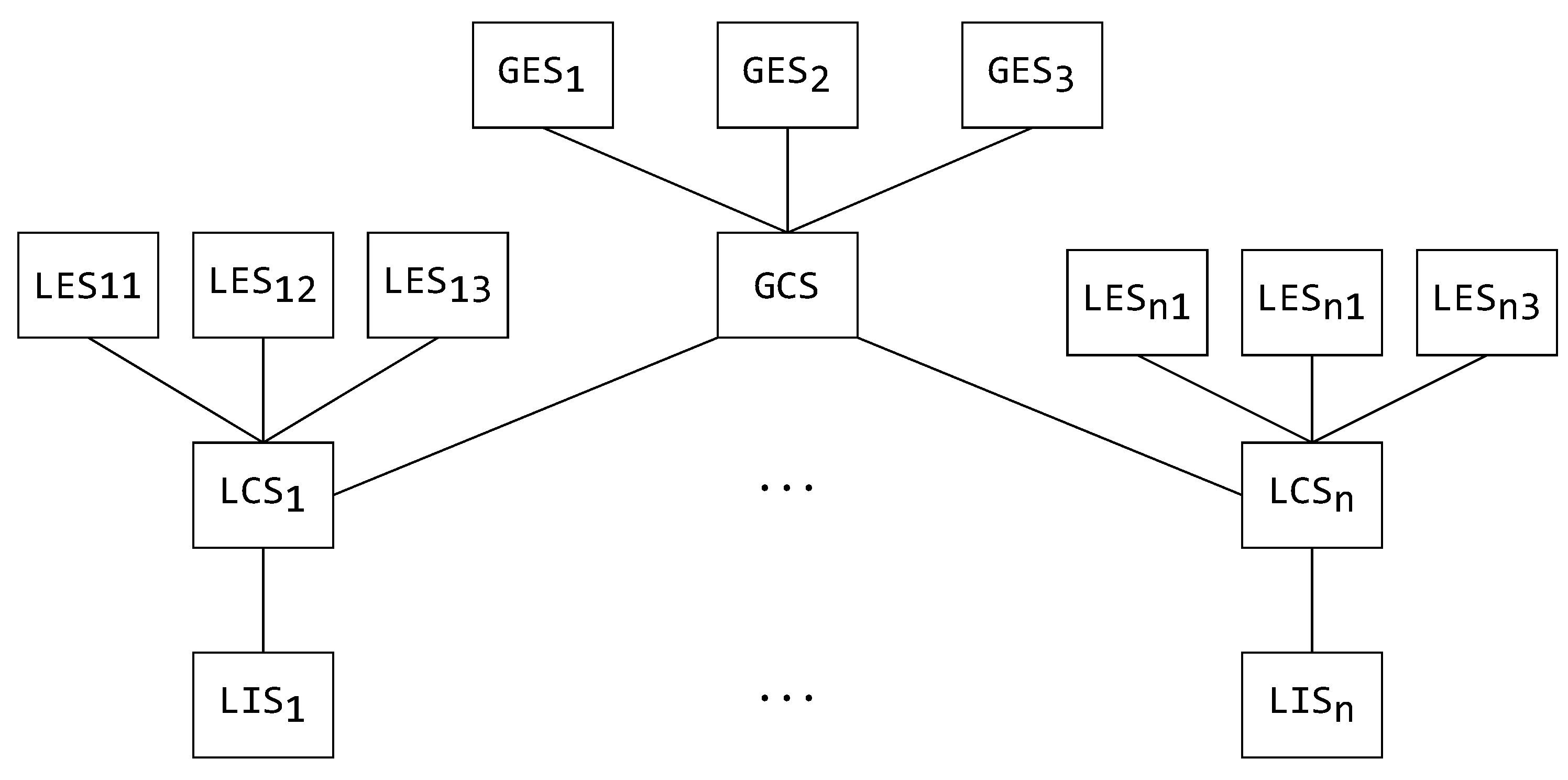
3.2. On Schema Hierarchies in the Mediator–Wrapper Architecture

One of the advantages of using a MW architecture is the ability to modularly translate schemas by using the architecture’s components themselves. To better understand these specifics, a generic example of a schema-type hierarchy is displayed in Figure 3, which shows all the possible schema types and their possible relationships. This is, in multiple forms, explained by [28].
Starting bottom-up in Figure 3, the first type of schema is a local internal schema (LIS). The LIS is the schema found in the connected data source itself, defined in the data source’s native form. For the data source integration system to be able to work on the connected data source, it must translate the LIS to a more generic and adaptable form that is used system wide—this is the local conceptual schema (LCS). The LCS can then be translated into a local exported schema (LES). The LES is, for all intents and purposes, a partial or transformed schematic view of the LCS. As the data source integration system does not use the LES for its internal functioning, the LES can be described in an entirely different form and presented to the user. The global conceptual schema (GCS) is created by integrating the local conceptual schemas. In turn, the GCS can also be exported to the user in multiple forms, just like the LES. Such an exported schema is called a global exported schema (GES).
In a multidatabase integration system, these schemas are all found in the same integration component in the form of metadata and are generated by modules. On the other hand, in a MW architecture data source integration system, these schemas are worked on gradually. This is done through the system’s wrapper and mediator layers, each layer creating a more encompassing global schema or creating new forms of exported schemas.
As an example, a certain system-wide schema hierarchy is presented in Figure 4 with the schemas’ relationships in accordance with the former explanation. The schema relationships (mergers or extractions) are presented by connecting lines, while the arrows on top of the schemas demonstrate which of them can be accessed by a user.
To set a concrete example, this paper displays how schemas should be assigned to MW components. Setting this example for the continuation of this paper, the schemas from the exemplified hierarchy (Figure 4) can now be assigned to MW architecture components. In Figure 5 and Figure 6, the components are displayed with their assigned schemas (illustrated by a white rectangle) adjacent to them.
The first possible assignment of schemas is to a system with a single mediator layer, as displayed in Figure 5. The LISs are positioned in the connected data sources. The wrappers then form their individual LCSs based on their connected data source’s LIS. The wrappers’ LCSs are then used by the mediators to create their GCSs. In this example, an aforementioned case of a mediator connected to a single wrapper is also displayed. This mediator generates a LES, and thus this mediator is only used for translation. The other mediators, along with their GCSs, generate GESs. A mediator can be used to create GESs to remove the need for another architectural layer of the mediators above. Of course, this might decrease system latency, but will increase the complexity of mediator components, as they now must manage multiple user role access.
Another example of a schemas’ assignment is displayed in Figure 6. In this example, there is another mediator layer on top of the architectural hierarchy. These mediators are used exclusively for exporting schemas, similar to the translating mediator. In this alternative, each mediator exports just one form of GES, thus reducing their task base and reducing the required complexity for multiple user role management. In other words, each mediator could have just one form of a data-accessing user.

4. Problems with the Mediator–Wrapper Architecture

So far, mentioning the way in which users connect and use these systems has been omitted. Multiple authors have opted for connecting users to the system via specialized applications which are system specific [31,33,34]. Such applications connect directly to the highest mediator layer (or the integration layer in case of an alternative architecture).
This puts additional responsibilities on the mediators in the higher layers. These mediators not only have to mediate schemas from lower layers, but also manage their GESs, as shown in the example of Figure 5. Opposed to this, the exporting mediators shown in Figure 6 seem like a better solution due to the functional responsibility being shared among multiple mediator components. This also has its issues. RMe1 prohibits the mediator from exporting data in a format that is not internally used by the system itself, meaning that data translation is going to have to be done in a user application. This breaches the system’s separation of concerns, leading to client applications having to perform the translations. It seems that this responsibility cannot be shared among components of the mediator type. Therefore, we add a third rule for mediators:
RMe3 
Mediators should be used to mediate, not to represent.
This problem is further exacerbated when one takes notice of the user applications usually implemented alongside these systems. Although user applications generally display just one format of data, it is interesting to notice the variety of data formats that have been used as presentational in different systems—from JavaScript object notation (JSON) collections [40,41] and extensible markup language (XML) documents [42], to tabular data [43,44]. The way of access can also be varying—a Java database connection (JDBC) API [44], web applications built onto the system [41] and even a web API [40].
This is also the case with state-of-the-art databases and frameworks designed with specific representations of data sources in mind. Some authors still show a preference for an SQL interface [20,21,38,45], while others prefer a key–value [19,22,23], graph [13,14,15], semantic web [17,18], an XML [46], flattened data [47], or a plain-text interface [48]. Pang et al. [11] also showed a system with three types of data representations: an object storage via a representational state transfer application programming interface [49] (REST API), file storage, and NoSQL tablestore service. Benedikt et al. [50] and Qin et al. [51] also showed that data representation (views) is becoming a key factor in data handling.
With the increase in data format variety (illustrated by Table 1), it is becoming more apparent that a data source integration system, as a singular data source, will itself have to support data representation in different formats. It is important to note that data, schemas, and queries face this same issue equally.
A more general point is that the MW architecture in its current state diverges from the idea of a clean system architecture. The clean architecture principles of architectural layering, separation of concerns, managing dependencies, control flow and testability are a solution to achieve a flexible and largely scalable system [52,53]. Such a system is an expected requirement for gathering and managing large amounts of data from multiple sources.

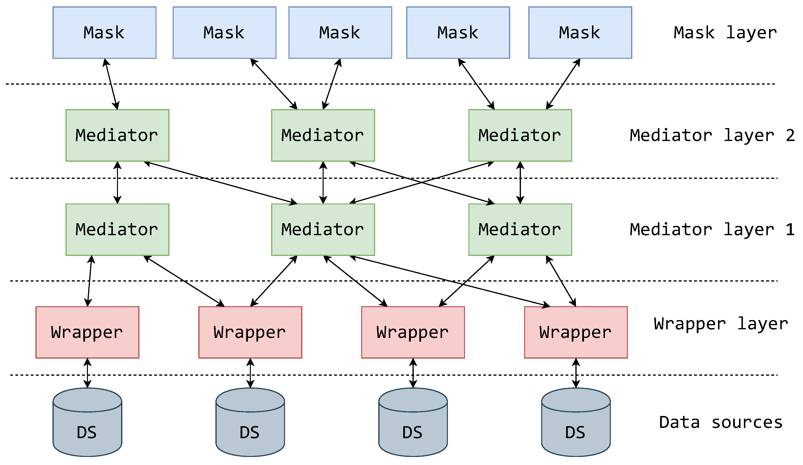
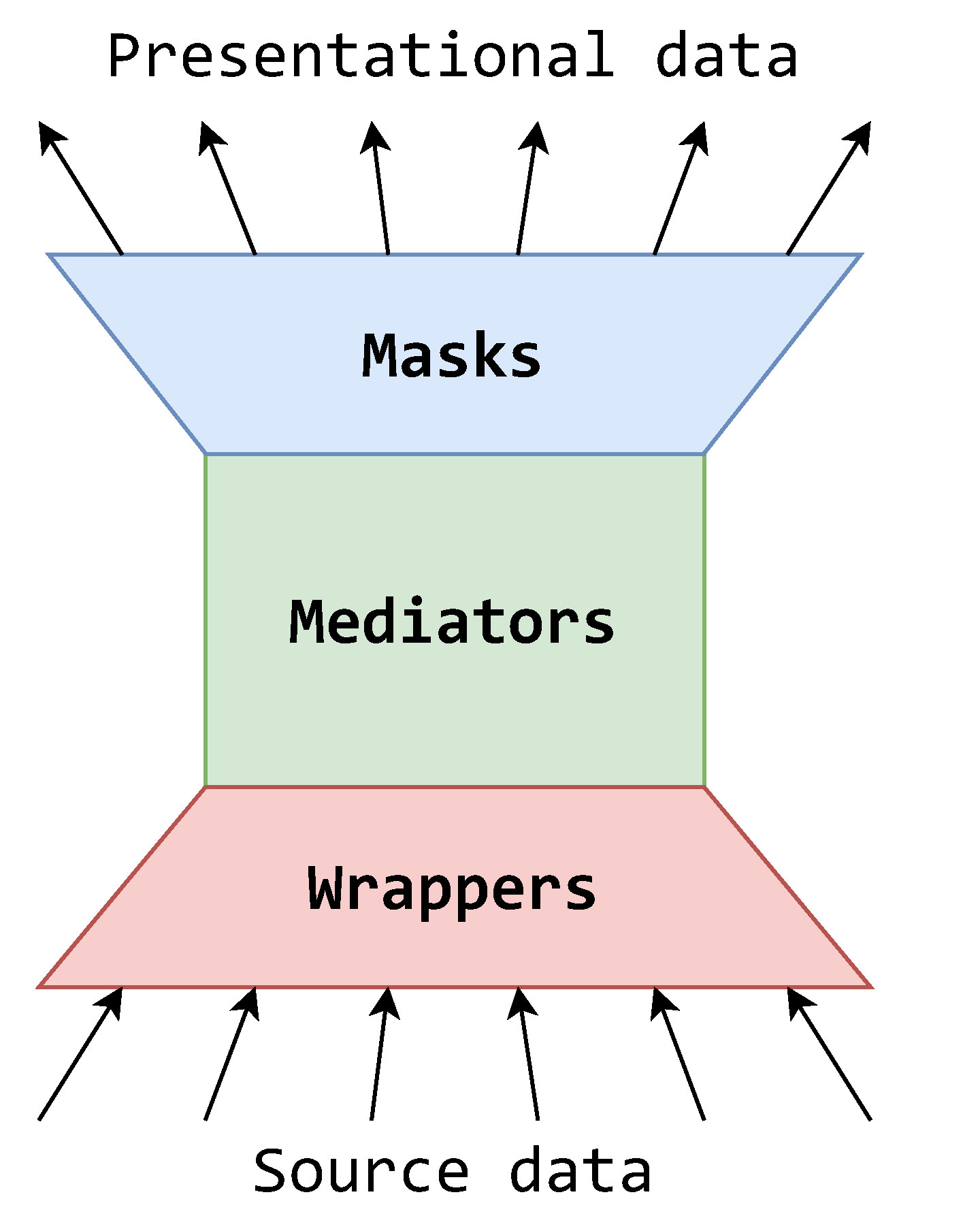
5. Extending the Mediator–Wrapper Architecture

It is evident that currently, in the MW architectural pattern, the responsibility of representing data, schemas, and queries cannot be assigned to any of the existing component types without assigning too much responsibility onto them. For this reason, the system designer is forced to decide whether to assign this responsibility to the highest mediator layer or a user application.
Due to the nature of the problem being the assignment of a system functionality to a component type, and all existing component types being finely utilized via their given rules, it has become obvious that there is a component gap in the upper layer of the MW architecture. In other words, due to RMe3, there is a task that no component type is adequate to additionally handle. Hence, there is a requirement for another type of system component that could take on the responsibility of representing system data.
Therefore, in this article, we propose a new theoretical component, which we name a mask. A mask masks the system at a certain point in the schema hierarchy into a representational form that can be easily handled by users, effectively taking on the responsibility of representing the system. The mask should be placed at the top of the architectural hierarchy, positioned between the users and highest mediator layer. Placing the masks on top of the architectural hierarchy effectively creates a mask layer. Consequently, this extended variant of the MW architecture is called a MMW architecture (Figure 7 displays the positioning and relationship of the mask components and layer with other components in the architecture).
Using the mask, the system’s representational logic is decoupled from the system’s mediation logic and the user’s application logic. Furthermore, by adding the mask as a system component type, the system has a finer separation of responsibility and gains benefits that help expand and simplify its usability. If a mask supporting a form of standardized technological access to data is implemented, then access to the system becomes available to a wide variety of applications implemented over that standard of access.
Observing the mask with an implementation example, one could implement a mask in the form of a REST service with requests over uniform resource locators (URLs) returning resources in JSON, akin to the system access shown in [40]. In this way, any application built to send requests to a REST service and receive its responses can now be used as a client application.
Another interesting way to look at a mask component is to imagine it as an inversed wrapper, as illustrated by the flow and dissemination of data in Figure 8. While the wrappers concern themselves with adapting the source data from the outside world to accommodate the data source integration system’s standard, the masks concern themselves with adapting the standardized data to accommodate the outside world. Additionally, wrappers import data from multiple sources, while masks export data to multiple destinations. Hence, the data source integration system can now be seen as a single logical point of collecting, transforming and providing data in various formats.
As was the case with wrappers and mediators, the rules for masks are set as follows:
RMa1 
A mask should be positioned at the top of the architecture.
RMa2 
A mask only connects to a single mediator.
RMa3 
A mask is used for representational purposes, representing a schema, querying data, and representing the result data.
RMa1 follows from the consensus that the presentation layer in system architectures is positioned at the top (furthest on the user side). The mask, its use being representation, is the system’s presentation layer.
RMa2 follows from the reversal of its statement. If the mask could connect to multiple mediators, then it would need to also apply mediation—breaking the separation of responsibilities among the components. Hence, a mask is allowed to connect to just one mediator, and all the mediation is left to the mediators.
RMa3 states a set of basic functional requirements that are expected of most data access systems. This rule articulates that the mask component does not in any way diminish the system’s functionality.
The mask component type is succinctly defined in Definition 3.
Definition 3.
The mask is a component used to manage representation of uniform schemas, queries, and data.

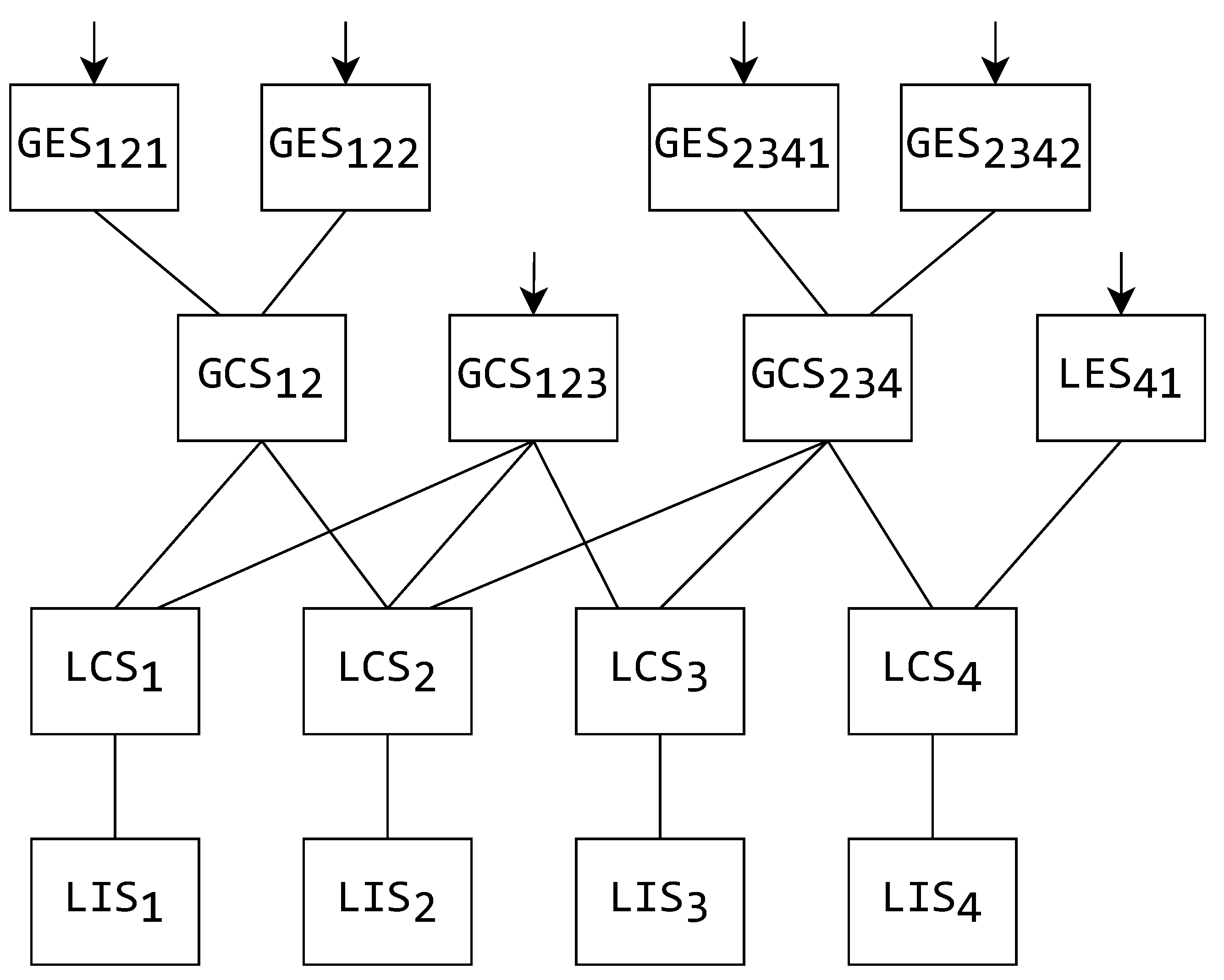
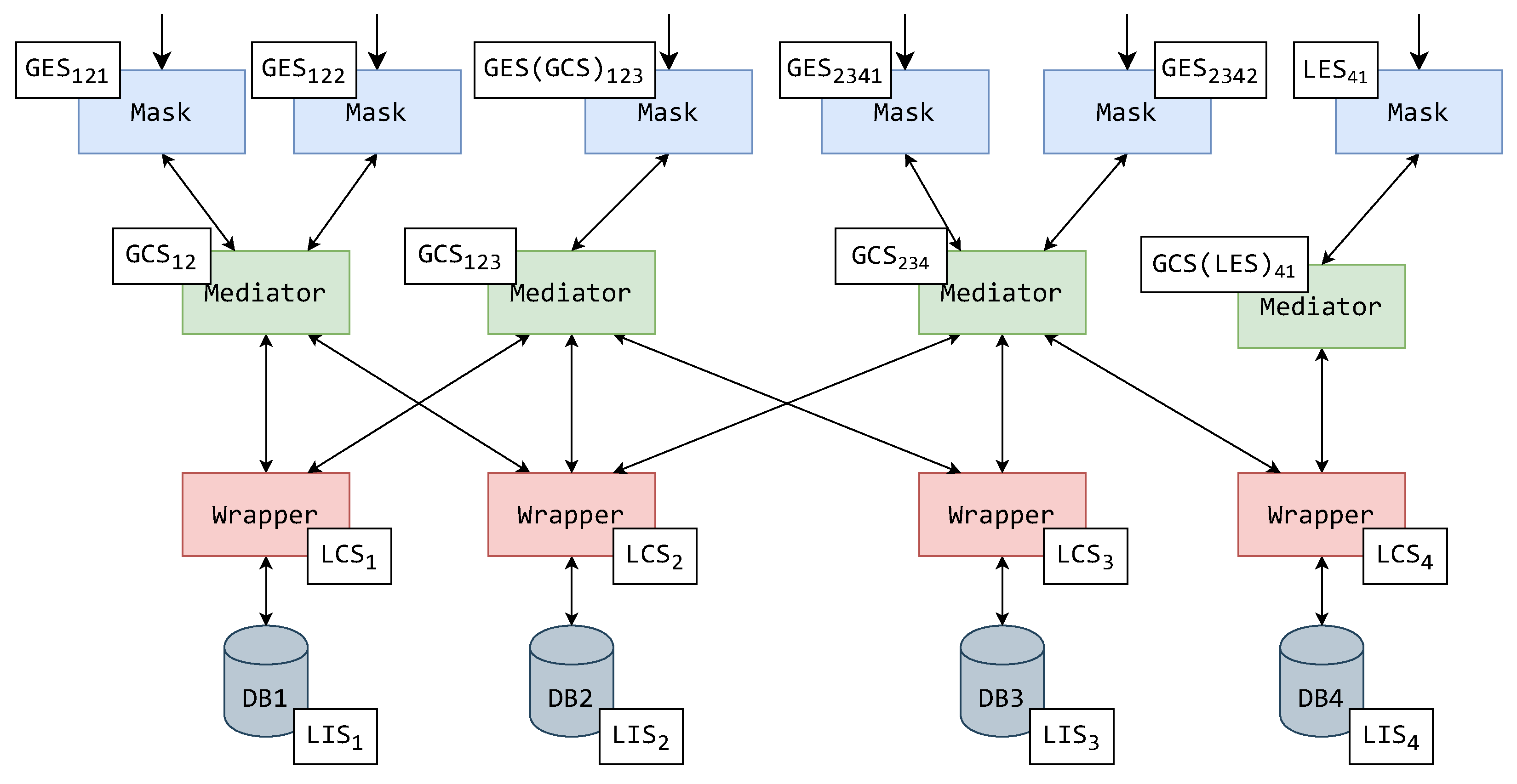
5.1. The Mask’s Effect on the System Schema Hierarchy

To show that the addition of masks affects only the mediators in the higher layers and decreases these mediators’ responsibilities, in Figure 9, the assignment of schemas from the system-wide schema hierarchy from Figure 4 is shown. As in Figure 5 and Figure 6, Figure 9 shows components and their assigned schemas adjacent to them in white rectangles.
The wrappers themselves and their schemas have remained unchanged, but there is a significant difference above the first mediator layer. It is important to note that the placement of prior existing components has not been changed—all the mediators still connect to the same wrappers, and the mediators all operate over the same GCSs. Analogous to the examples shown in Figure 5 and Figure 6, the mediator components of the (now only existing) mediator layer operate over their respective GCSs. The mask components have been assigned all the GESs.
There is a noteworthy schema rename in the example of Figure 9, for what was originally GCS123. As the GCS123 itself was an exported schema in prior examples, in this example, the schema might be in a fundamentally different format. Hence, the schema operated over in the mask cannot be named the same as the schema in the mediator. To mark this change, what was once GCS123 used for exporting is now GES123—a fully fledged exported schema.
A similar effect can be seen in the case of the mediator that in Figure 5 and Figure 6 is operated over the LES41. As this mediator’s schema is not directly exported, it is renamed GCS41, although it currently only incorporates LCS4. The mask component above this mediator has taken the responsibility of representation (exporting) and is consequently assigned LES41.
There is also an interesting case in Figure 9 concerning the translation of schema LCS4 to the upper layers (via LCS4, GCS41, LES41) and the components used for this task. The previously exporting mediator of LES4 from Figure 5 and Figure 6 is preserved. This mediator’s schema is also renamed to GCS41, as stated earlier. For the moment ignoring the RMa2, it can be questioned whether this purely translational mediator is even required—rightly so, if it is additionally considered that the system probably uses standardized interfaces for inter-component communication. It could be concluded that the mask with LES41 could be connected directly to the wrapper with LCS4.
However, this is not the case, as the mediator with GCS4 (formerly LES4) must be preserved. The reason for this statement is two-fold from the angle of system design. Firstly, the mediator is not only used for translation, but also enables transformations within the schema itself (as is stated by RMe2). Connecting the mask directly to the wrapper, although feasible, would disable the system to apply further transformations on schema LCS4. Secondly, the benefit of using a MW architecture, and by extension our own, is the ability to append data sources after the system has been set up. Connecting the mask directly to the wrapper leaves the system without a mediator to mediate between the wrapper with LCS4 and any additional to-be-connected wrapper. Because of this, the system would lose the beneficial property of being (completely) appendable.
This is an example of how the RMa2 preserves not only the component hierarchy of the architecture, but also the properties of the system itself.

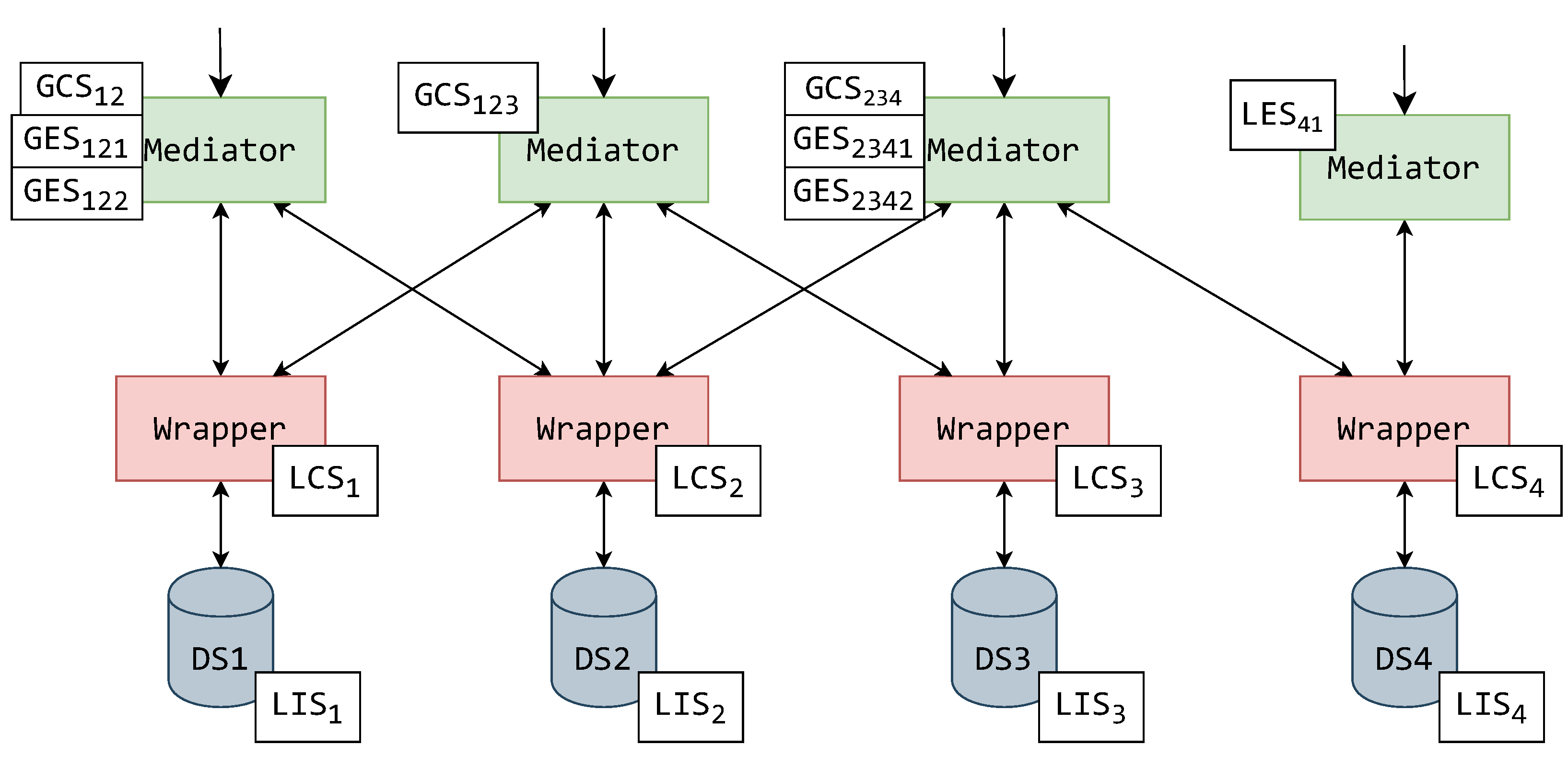
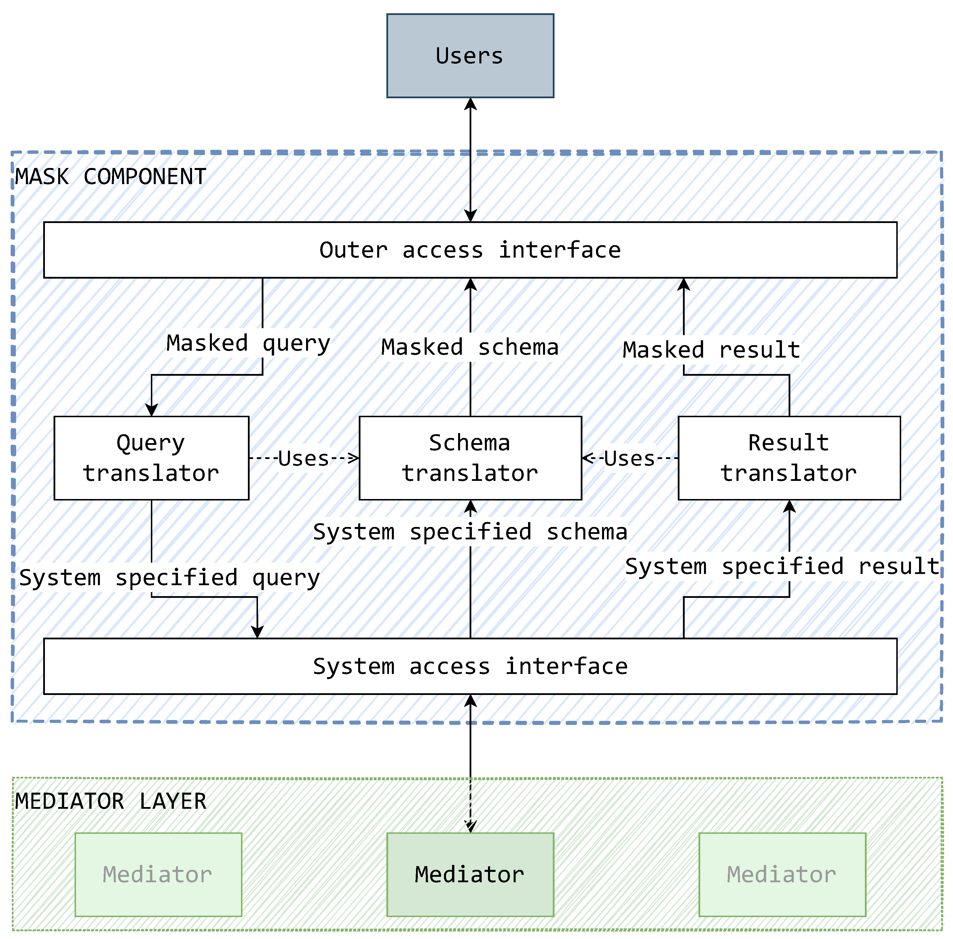
5.2. On the Implementation of a Mask

The general practice in this paper up to this point was to analyze the mask as a generic black box component and explain how it would work in synthesis with other system components. To expand the idea of the mask even further, it can no longer be observed just as a black box. The possible inner workings of a mask give the ability to distill this architectural component even further in terms of design and development. As with most software systems, the mask, a miniature system itself, can be internally elaborated by following some functional requirements.
Using the mask’s properties that have been introduced via its defined rules, relations to other components, and effect on the architectural layout, we introduce some basic functional requirements:
F1 
The mask must interface with the system via mediators. The mask connects to just one mediator, but it should in general be able to connect to and communicate with any system mediator interchangeably. A connection with a wrapper is feasible, but it is inadvisable and thus not of primary concern.
F2 
The mask must provide a user access interface. The user access interface is the point of user system access. This interface can take any implementational form, provided that the chosen form has presentational abilities for data storage concerns. This interface is interchangeable and does not have effect on the general way in which data source component translations take place.
F3 
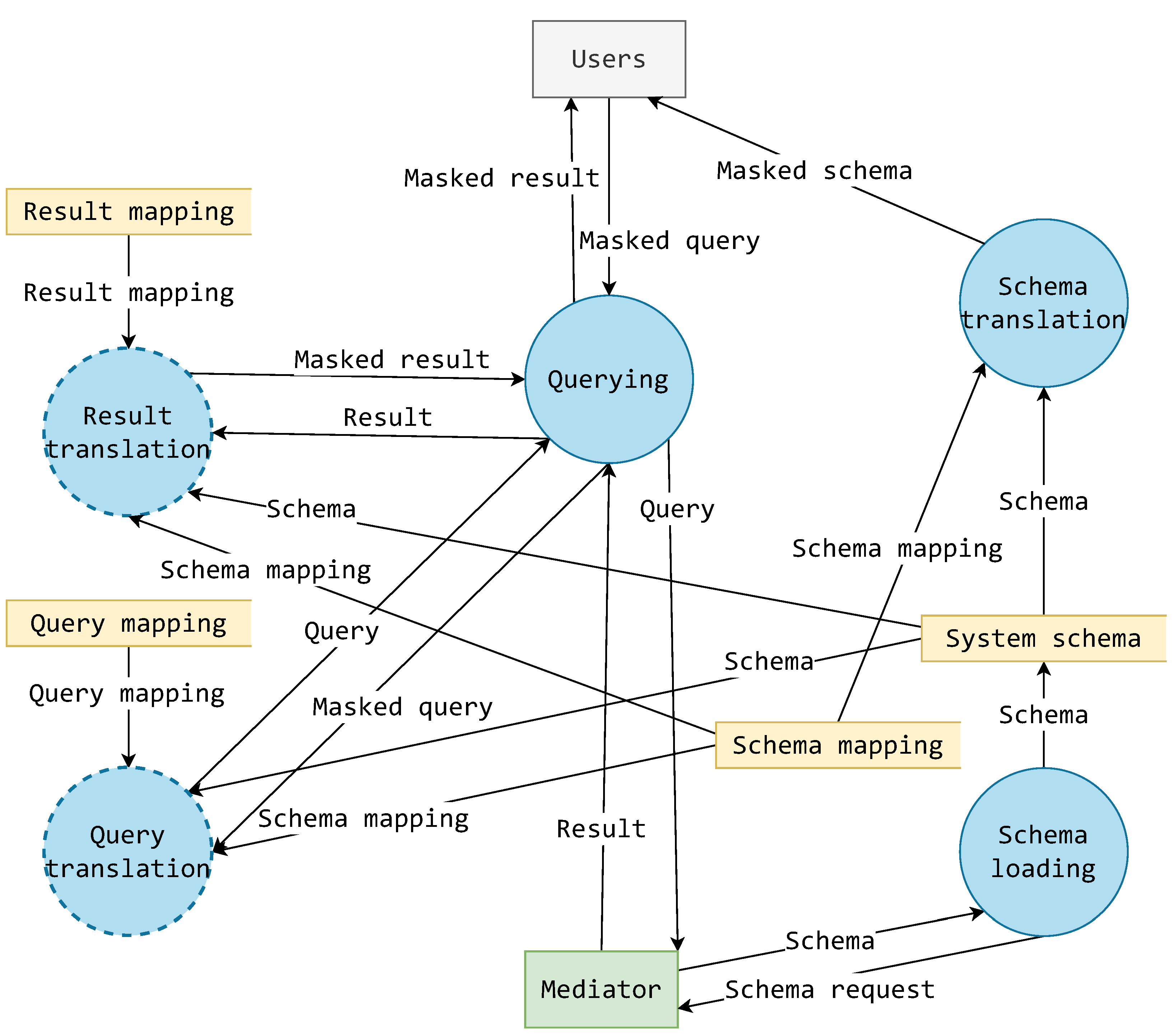
The mask must translate schemas from the system format to the user access (masked) format. The mask ascertains the system schema provided by its connected mediator and adapts the schema to a defined mask format.
F4 
The mask must translate queries from the user access (masked) format to the system format. The queries are given by the user through the user access interface in a masked format and are translated to the system format. To determine mask-to-system element mappings, the query translation can use the results of schema translations.
F5 
The mask must translate results from the system format to the user access (masked) format. The results received through the system must be adapted to the defined mask format. To determine certain metadata aspects (e.g., the naming of attributes) of the data results, the results of the schema translations can be used.
The requirement F1 follows from RMa1, F2 from RMa2, and the requirements F3, F4 and F5 from RMa3.
Following these functional requirements, a conceptual depiction of the mask’s inner components is devised. This is displayed in Figure 10 as a conceptual model of functional components and the types of data they are expected to handle. These components present a generalized idea of what kind of functionalities a mask should have and what their relationships should be in terms of data exchange and dependency. These components do not present real-world components, but rather a possible grouping of some real-world components providing a functionality.
This sketch allows the mask’s functionalities to be put into context. The schema, query, and result translators are recognized as components with the task of translating data source components. The central role in translation is given to the schema translator as queries and query results are translated by using schemas generated by the schema translator. The system access interface is used to connect to the system via a mediator in the layer below. The outer access interface is a generic component, able to accommodate an adequate form of an access interface.
A noticeable trademark of this model is that there is a focus on the flow of data and its conversion by the components. A masked query is translated and sent (down) into the system. Reciprocally, the result of such a query is translated into a masked format to be sent (up) to the user. Similar is the case of schema translation; the system specified schema is translated into a masked schema for presentation to the user.
Such data transformations can only be achieved through processes, so in a general sense, it is more sensical to discuss the mask in terms of processes and the data that flow between them. To achieve a more detailed elaboration of the mask, building upon the model from Figure 10, a data flow diagram is constructed as displayed in Figure 11. Figure 11 displays the recognized processes as circles, outer entities as rectangles (users and mediator), data storage as open rectangles, and flowing data as named arrows.
On the right-hand side of Figure 11, the schema translator of Figure 10 is decomposed as two processes: schema loading and schema translation. The schema loading process is concerned with the acquisition of a system schema from a connected mediator. This schema is also stored for other usage, besides schema translation, but it should be reacquired frequently to maintain an up-to-date schema. For this reason, schema loading is considered a separate and independent process. The schema translation process uses the currently acquired system schema and schema mapping rules from a separate storage to create a masked schema. This masked schema is presented to the user.
The querying process in Figure 11 is a complex process that concerns itself with querying over a mediator. It is closely tied with processes of query translation and result translation. These processes are effectively subprocesses of querying but have been extracted due to their importance and correlation with components in Figure 10.
The query translation process translates a masked query into a system formatted query. It requires data about the current system schema and schema mapping rules to determine the way in which they are reflected onto the current query. This must be considered, as the schema translation might change the resources’ names or change their schematic, so it becomes important to reverse those translations when constructing a system query. The query translation process also requires query mapping rules. As a general example, and for the moment setting a simplified generic model for a query—these rules might explain how a projection or selection in a query is to be translated.
The result translation process also requires data about the current system schema and schema mapping rules, as it is also concerned with translating a small view-like portion of the schema with the addition of holding result data that can also go through some masking transformations. Just like in other translational cases, result data translation also requires some mapping rules for data results.
There is also a very interesting feature of the diagram in Figure 11 regarding all the mapping (rules) data storage. The result mapping, schema mapping, and result mapping data storage do not have any data inflows. These mappings are, in the context of this diagram, then clearly provided by some other undefined source. In fact, these mappings can only be provided by the developers of a certain mask component. These mappings are the exact point at which the system can no longer be designed as generic or abstract, and some concrete implementation or empirical data describing the masking of the system is required.
Considering the mentioned findings, a conceptual component design for a mask is proposed and shown in the diagram of Figure 12. The goal is to also to think of the mask’s component design without reducing generality to avoid prescribing any concrete programming paradigms, languages, or specific design patterns. Figure 12 illustrates the recognized components of a mask as white rectangles (cylinder in the case of a metadata database), required implementations for a mask kind as gray rectangles (implementation indicated by arrows with empty arrow-heads), and data flow as arrows with black arrow-heads.
Following the process inference of the data flow diagram of Figure 11, in Figure 12, the schema manager and schema translator (interface) are recognized as components—analogous to the schema loading and schema translation processes, respectively. The schema manager observes the system schema and updates the stored system schema appropriately.
The inference of a general querying process in the data flow diagram leads to the recognition of the query manager component. This component manages the underlying translations and query execution sequencing. In general, its purpose is to produce a masked result for a masked query. This is achieved through the processes of query and data result translation, which themselves in turn lead to the recognition of the query translator (interface) and data result translator (interface) components.
Regarding the mask’s communication abilities with the rest of the system, the mask sends system format queries and results, just like mediators and wrappers. For this reason, the mask can use a standardized communication node (module) used in all other component types. Due to the communication restrictions of the mask (allowing for a single mediator connection), an extension of a basic communication node should also be implemented. This also allows the addition of new message types if such a requirement should arise later.
To store all the data inferred for storage in Figure 11, a metadata store should also be introduced to the component. Such a store would be used by all components that require at least some schematic information or technical information. In Figure 12, this store is displayed, but the connections to other components are omitted for the sake of clarity.
On the other hand, the mappings (marked as data storages in Figure 11) are not stored in the metadata database. They are presented by the component implementations (marked gray) in Figure 12. For the mask to remain as generic as possible, such mapping rules are explicitly described by the schema, query, and result translator implementations. The aforementioned interfaces are used to keep a level of abstraction toward the other inner components. The implementations are case specific and created by the mask’s developers according to their respective interfaces. This allows the development of a mask kind to be done without the need for extensive coding, as only the missing implementation pieces need to be filled in. This, by consequence, not only simplifies the development process, but also decreases the time required to develop a certain kind mask component.
It is important to note that the term “interface” is used in its broadest form here, not excluding the development of the mask component in a non-object-oriented paradigm language (non OOP). Along with these interfaces being implemented as standard OOP interfaces, they can also be implemented as high-order functions in a functional paradigm or as separate implementations of function prototypes defined in library headers (to be linked before compilation) in a structural–procedural paradigm. This is one of the beneficial results of generic and abstract reasoning about mask components.
The inner components that have been elaborated up to this point are part of a mask module, or rather a library. This is best understood from the point of another component marked gray in Figure 12—the mask application. The mask application is the execution entry point of the mask component. In the continuation of previous possible use-case examples, this component could be a web API or a TCP server listening for JDBC. Whichever the exemplified case, it would use the mask module as a library to connect to the integration system. The interfacing of the mask application and the module is achieved through the mask application interface that provides a universal interface for data storage. In essence, the mask application interface provides the following:
  • The acquisition of a mask schema;
  • Querying via a masked query;
  • Receiving masked results.
A well-designed mask module allows developers to treat it as a simple native data provider without the need for additional transformations. Of course, the achievement of such a property is also dependent on the developer’s ability to provide schema, query, and result translator implementations fitting well with the implemented mask application.
If such design generalizations were not considered, the development of each kind of mask component would create a lot of excess repeated work and increase the overhead workload, as all aspects of a mask would need to be re-implemented and retested. Such development would also have an impact on the management of multiple mask kind codebases, as none would conform to any design standard.
Keeping in form with the proposed design, the development of a mask-type component is narrowed down to the implementation of just four components:
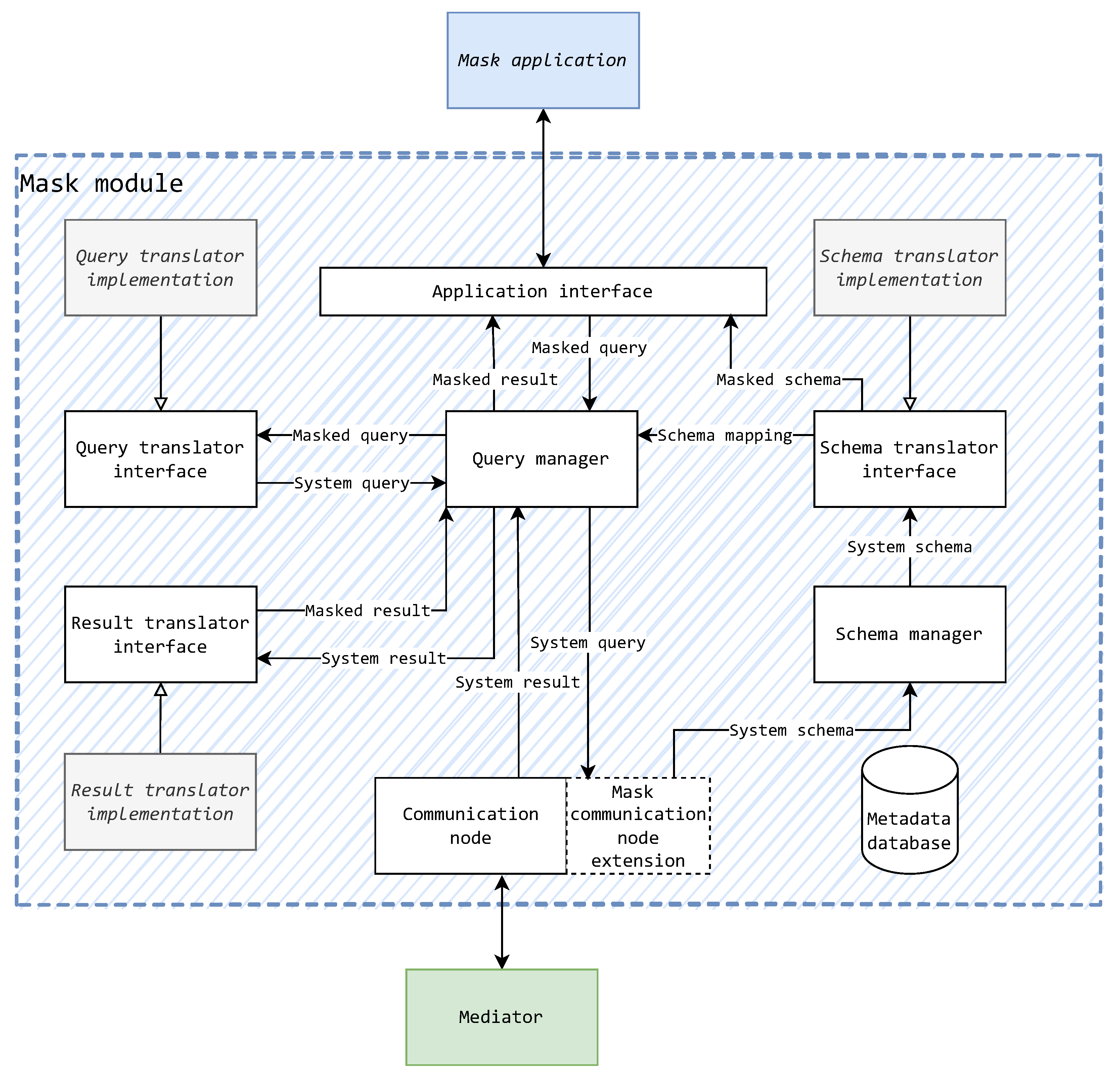
  • Schema translator implementation;
  • Query translator implementation;
  • Result translator implementation;
  • Mask application.
This obviously reduces the workload and time required to implement a mask component, removing the need for the re-implementation of core components. The development along the proposed design allows logical layering of the mask component in the segment of the mask application, as the mask module can be treated as a provider or service. Such standardization allows the mask components to be potentially built, tested, and maintained by a community of developers in the form of an open-source software initiative.

5.3. Quantitative Analysis on Scenarios

To prove that the MMW architecture simplifies a MW-based data source integration system’s maintenance and change management, a leveled quantitative analysis to compare the MMW and MW alternatives is needed. The following analysis is based on an evolution–cost quantitative analysis for measuring software flexibility described by [54].
Eden and Mens [54] proposed that a software’s flexibility can be measured and compared to other designs by approximating the cost of implementing anticipated changes—shifts. The cost of shifts is defined as the quantity of software units that need to be changed, added, or removed. These software units are called modules in a general sense but are exemplified with classes and methods in the paper.
To adjust this analysis for the level of architecture design in this paper, the modules are viewed as architectural components. The analysis compares an isomorphic example (shown in Figure 13) of a MW architecture with one mediator layer (1LMW), a MW architecture with two mediator layers (2LMW), and a MMW architecture. In the cases of 1LMW and 2LMW, mediators are considered to have functionalities of both mediation and representation. The 1LMW and 2LMW architectures were chosen for this analysis because they generally represent the solutions of the GARLIC and TSIMMIS system architectures. The GARLIC has been presented as both a 1LMW and 2LMW system, while the TSIMMIS has been presented as a 2LMW system. In Figure 13, red rectangles represent individual wrappers, green rectangles represent both mediators with representational functionality and mediators without (tick marks representing names of mediators without representational functionalities), and blue-green rectangles represent masks in the MMW architecture and mediators in the 2LMW architecture.
The analysis is conducted over four scenarios: adding a new representation type, adding a new representation, adding a new mediator, and adding a new wrapper to a mediation. The symbolic nomenclature for this analysis is defined as follows:
For a set of components S c o m p of possible types S c o m p t y p e s = { M a , M e , M e , W } representing a mask, a mediator with representational functionality, a mediator without representational functionality, and a wrapper respectively, and a set of possible actions over those components S a c t = { i m p l , d e p l } representing implementation and deployment respectively, C X Y us the cost of performing an action Y S a c t over component X S c o m p , with the addition of C C o n n s e t signifying the cost of setting up a connection between a pair of components { ( c 1 , c 2 ) c 1 , c 2 S c o m p }
Since a mediator with representational functionality is more complicated to implement than a mediator without representational functionality, the cost of implementing the former is greater than the latter:
C M e i m p l > C M e i m p l
Due to a greater number of functionalities that need to be supported by the surrounding system to which the component is being deployed, the deployment of a mediator with representational functionality is also more costly than that of a mediator without representational functionalities. This is because their deployment includes the tasks of setting up system resource access permissions, component settings, and firewall rules, all of which are either increased in quantity or complexity in the case of a representational mediator. Therefore, we conclude the following expression:
C M e d e p l > C M e d e p l
As in the former statement, for the same reasons, the deployment of a mask component is considered less costly than a mediator with representational functionalities. In addition, the mediator has a communication node intended for access to multiple sources. This is considered bloat, as the representational components connect to only one component in the lower layer. The mask, on the other hand, has a communication node inherently allowing just one connection to the lower layer (as per RMa2), making the connection configuration simpler. Therefore, we conclude the following expression:
C M e d e p l > C M a d e p l

5.3.1. Scenario 1: Adding a New Representation Type

In this scenario, a requirement for a new representation type on top of the combined schemas of wrappers W 2 , W 3 , and W 4 is added. Since a new type of representation is required, in a 1LMW, an entirely new mediator must be implemented. This new mediator also must be deployed and connected to wrappers W 2 , W 3 , and W 4 . The outcome of the shift on 1LMW is displayed in Figure 14 (added elements are marked with dashed lines), with the addition of M e 4 and its connections to the required wrappers.
Thus, the cost of the shift is
C 1 L M W 1 = C M e i m p l + C M e d e p l + 3 × C C o n n s e t
In a general case, with the number of connected wrappers being N, the cost is
C 1 L M W 1 = C M e i m p l + C M e d e p l + N × C C o n n s e t
It can be noticed that this architecture forms redundant connections between wrappers and mediators, adding to the shift cost.
Again, in the case of a 2LMW, a new mediator must be implemented and deployed ( M e 7 ). In this case, the mediator is stacked on top of a mediator on the lower layer of mediators ( M e 3 ). Hence, mediator M e 3 is reused for combining wrappers W 2 , W 3 , and W 4 , and only one connection is set up. The outcome of the shift on 2LMW is displayed in Figure 15, where the added mediator component and connection is illustrated with dashed lines.
The cost for this shift is
C 2 L M W 1 = C M e i m p l + C M e d e p l + C C o n n s e t ,
which remains true for any general case.
In the case of a MMW architecture, to create a new type of representation, a new mask ( M a 4 ) is required to be implemented and deployed. Only one connection setup is required, as the new mask only connects to one mediator in the mediator layer ( M e 3 ). It is important to note that the mediators in this architecture do not serve a representational purpose, so they do not have representational functionality. The outcome of the shift on MMW is displayed in Figure 16, with the added mask component and connection illustrated with dashed lines.
The shift cost in this and general cases is
C M M W 1 = C M a i m p l + C M a d e p l + C C o n n s e t

5.3.2. Scenario 2: Adding a New Representation

In this scenario, a requirement for a new representation on top of combined schemas of wrappers W 1 and W 2 is added. The representational component is already implemented, so none of the cases will have an implementation cost, just the deployment cost and the cost of connection setup.
In a 1LMW, the new mediator is deployed, and two connections to the two wrappers W 1 and W 2 are set up. The shift cost is
C 1 L M W 2 = C M e d e p l + 2 × C C o n n s e t
In a general case, the shift cost is determined by the number of required redundant connections to wrappers N:
C 1 L M W 2 = C M e d e p l + N × C C o n n s e t
In a 2LMW, a new mediator is deployed, and one connection to its underlying mediator ( M e 2 ) is set up. The shift cost is
C 2 L M W 2 = C M e d e p l + C C o n n s e t
In a MMW architecture, a new mask is deployed, and one connection to its underlying mediator ( M e 2 ) is set up. The shift cost is
C M M W 2 = C M a d e p l + C C o n n s e t

5.3.3. Scenario 3: Adding a New Mediator

In this scenario, a requirement for a new mediator over wrappers W 2 and W 3 is added. It is assumed that this type of mediator already exists, so there is no cost of implementation.
In a 1LMW, a mediator is deployed and connected to the two wrappers. The shift cost is
C 1 L M W 3 = C M e d e p l + 2 × C C o n n s e t
Again, for a general case where N is the number of connected wrappers, the shift cost is
C 1 L M W 3 = C M e d e p l + N × C C o n n s e t
In a 2LMW, a mediator must be deployed to the lower mediator layer to combine the wrappers and a mediator in the upper mediator layer to provide the representation. The set-up connections also must be considered, as two connections are set up toward the wrappers and a single connection between the mediators. The shift cost is
C 2 L M W 3 = 2 × C M e d e p l + 3 × C C o n n s e t
In a general case, where N is the number of connected wrappers, the shift cost is
C 2 L M W 3 = 2 × C M e d e p l + ( N + 1 ) × C C o n n s e t
In a MMW architecture, together with deploying a mediator, a mask must be provided. The mask type is considered as already implemented (analogous to the cases of MW architectures), so it has to only be deployed. Two connections are set up toward the wrappers and a single connection between the mediator and mask. The shift cost is
C M M W 3 = C M e d e p l + C M a d e p l + 3 × C C o n n s e t
In a general case, where N is the number of connected wrappers, the shift cost is
C M M W 3 = C M e d e p l + C M a d e p l + ( N + 1 ) × C C o n n s e t

5.3.4. Scenario 4: Adding a New Wrapper to an Existing Mediation

Additionally, to demonstrate that these architectures are sound (the MMW architecture first and foremost), a scenario of adding a new wrapper can be analyzed. The appending of wrappers to an existing mediator does not impact the rest of the components, as the wrapper is deployed and a single connection to the required mediator is set up. Thus, the shift cost for all architectures is
C 1 L M W 4 = C 2 L M W 4 = C M M W 4 = C W d e p l + C C o n n s e t

5.3.5. Analysis of the Shift Costs

With the shift costs evaluated, a more concise comparison of architectures can be made. Table 2 displays all the shift costs for each scenario and architecture.
The first scenario demonstrates that in the MMW architecture, the addition of a new type of representation is only dependent on the implementation and deployment of a mask component. The other two architectures depend on mediator components. The 1LMW shift cost noticeably depends on the number of connected wrappers—to emphasize, for adding a representation type. The 2LMW and MMW architectures are not at such a disadvantage, their difference being the type of component added to the system. Since a mask is less costly to implement and deploy than a mediator, the overall shift cost in scenario 1 is lowest in the MMW case.
The second scenario also shows that the 1LMW shift cost is dependent on the number of wrappers. The cases of 2LMW and MMW are again analogous, but a mask is less costly to deploy than a representational mediator. This makes the shift cost of the MMW case the lowest again. As it was discussed earlier in the text, using a mediator just for representation, without using its mediation functionalities, is akin to killing a fly with a cannonball.
The third scenario shows the shift cost overhead that 2LMW and MMW have as opposed to 1LMW when setting up mediation. There is an obvious trade-off in these architectures between the shift cost of adding mediation or representations. To maintain a less costly (and qualitatively simpler) representation addition, the overhead cost of adding mediation is increased. This overhead can be quantified for 2LMW as
C 2 L M W o v e r h e a d = C 2 L M W 3 C 1 L M W 3 = C M e d e p l + C C o n n S e t ,
and for the MMW,
C M M W o v e r h e a d = C M M W 3 C 1 L M W 3 = ( C M e d e p l C M e d e p l ) + C M a d e p l + C C o n n s e t
Considering that the MMW mask and mediator are less costly to deploy than the 2LMW mediator, the overhead cost is reduced in favor of the MMW.
The fourth scenario shows that the addition of a new wrapper to the MMW system has no effect on the rest of the system hierarchy, as it is also expected of the other MW architectures. The MMW finds itself in no detrimental opposition to the other architectures.

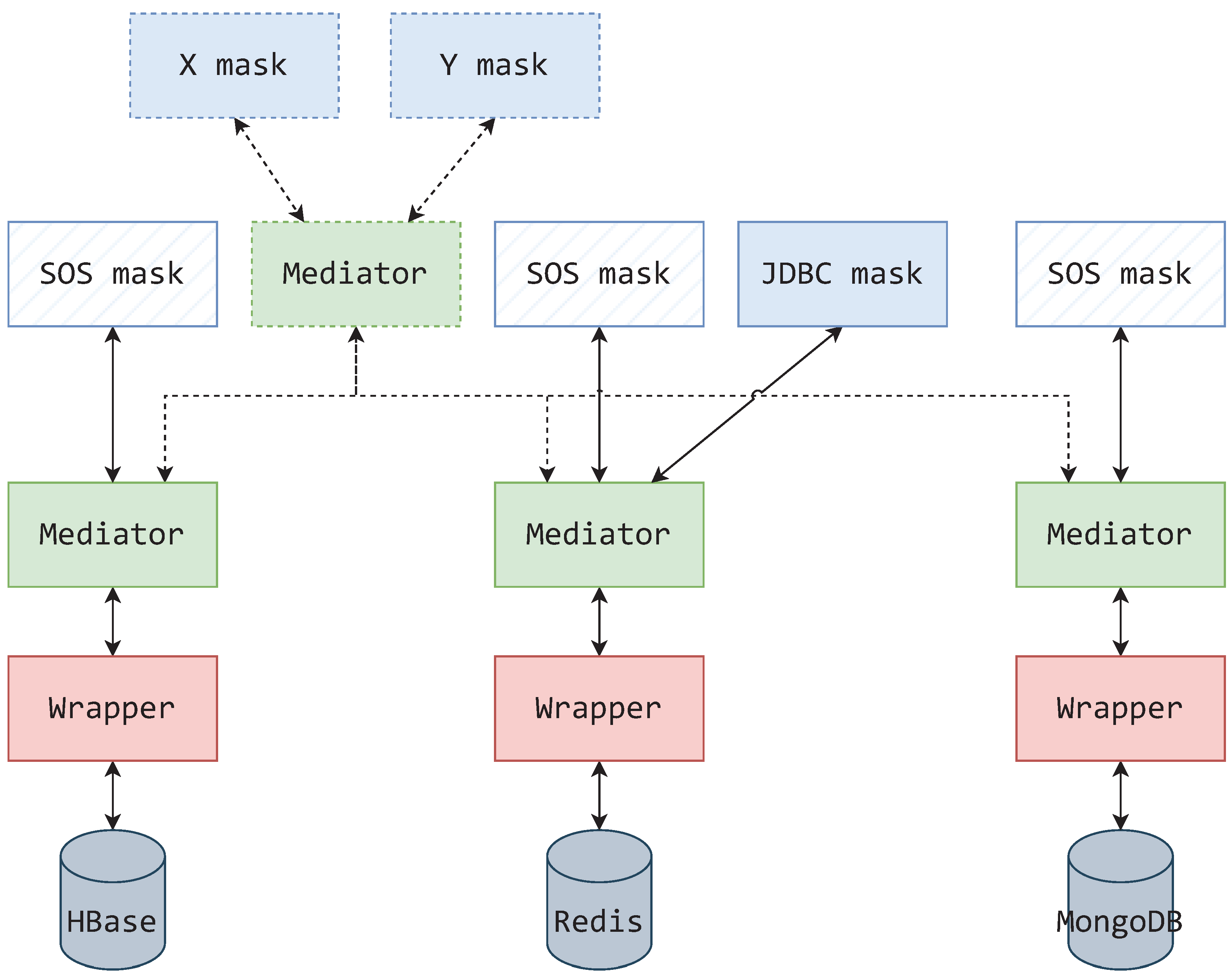
5.4. Hypothetical Implementational Example

As referenced before, Atzeni et al. [40] presented SOS (Save Our Systems) as a system for uniform operations over non-relational stores. The representational format of this system was a web API with URI-like resource identification, serving result data as JSON objects. They also defined generic wrappers (in their case as modules), which are implemented per data store kind. The wrappers in their case also concern themselves with representing the underlying systems. Although not a data source integration system itself, the SOS system could keep its raison d’être and be conveniently extendable to the likes of a data source integration system if it were reimagined following the MMW architecture. Additionally, using different mask kinds, the representational form of these data storages could be expanded on.
A hypothetical example of such a system use case is presented in Figure 17, where the revised SOS system provides uniform access over a single HBase, Redis, and MongoDB database. At the top of the component hierarchy, each database must be converted to the SOS interface for application access, as presented by [40]. This interface can be presented via mask components of the SOS mask kind.
Starting from the bottom of Figure 17 hierarchy, observing only solidly outlined elements, a wrapper is connected to each data source. Since it is not advisable to connect masks directly to wrappers and following RMa2 stating that masks should only connect to mediators—a single mediator is connected to each wrapper. A SOS mask is connected to each of these mediators, thus encompassing the original SOS system’s functionalities. These settings do not restrict the system to just using a SOS mask. Additional mask kinds can be connected to these singular mediators to offer an alternative presentational form and keep in line with the SOS use case of uniform system access. Such an example is given in Figure 17 with a JDBC mask representing the Redis database.
The singular mediators are of a translational nature, but also enable the system hierarchy to be expanded. If, by example of the mediator shown with a dashed outline in Figure 17, a mediator connecting to each of the singular mediators is provided, then that part of the system becomes a data source integration system. Consequently, the integrating mediator allows connections coming from different masks.
Not only does the MMW architecture allow the emulation of a system, such as the SOS, but it also expands on it. If it were not for the mask components taking on the responsibility of system representation, all mediators would have to be adapted (redesigned and reimplemented) to the SOS interface standard to work as both the SOS system and a data source integration system, which itself does not explicitly require adherence to the SOS interface standard. In effect, the use of the MMW architecture enables standardized implementation of mask kinds dedicated to data representations from Table 1 (illustrated in Figure 17 as masks X and Y).

6. Discussion

The MW architecture has numerous advantages when it comes to implementing a data source integration system, especially if the system is expected to connect a larger number of data sources. As was also demonstrated in this paper, when certain rules are followed to keep the components well formed, the maintenance of such systems also becomes easier. In the case of appending new data sources, they are each assigned a wrapper, and the wrappers are connected to selected mediators. In the case of managing schemas, this management is modularized by the system architecture itself. Workloads on hardware can also be balanced, as components can be set up on different machines.
Although it was mentioned that some authors did not use the MW architecture in terms of system components, most of them recognized these advantages and modeled their inner system modules to work in a similar fashion. This allowed them to at least use the advantageous modularization of tasks and responsibilities in a data source integration system.
The architectural pattern’s idea was agreed with up to a point, this point being the representation of data to users and the responsibilities of upper layer mediators. It was found that there is a responsibility of representing data that usually are either delegated to the upper layer of mediators or specialized user application. The former case has made systems less flexible and maintainable, while the latter has greatly limited the types of access and data representations that systems support. To keep the responsibility of data representation inside the system, the idea of a new architectural component was proposed—the mask. As with mediators and wrappers, some basic rules for masks have been set to assure that they are well formed and fit into the MW architecture.
The mask takes on the responsibility of representing data and creating an interface for users to connect to. It was also reasoned that appending masks to a MW architecture technically creates a new architectural layer—the mask layer.
By using the mask layer, a data source integration system increases its representational versatility and thus, its usefulness. Now a data source integration system can be viewed as a singular source of data but through multiple masked sources. In addition, if masks adhere to a certain representational standard, then the data source integration system becomes open to different kinds of user applications.
The mask component was internally detailed as much as possible in an abstract and generic form to prevent any partiality to a specific programming language or paradigm. Reasoning about the mask’s hypothetical functional requirements has progressed to a simple functional component structure. This basic model was then enriched by recognizing processes that a mask should support, leading to a more detailed conceptual inner-component design. This process also allowed thinking about a more concrete placement of the mask component in a real-life implementation, which was concluded with the proposal that a mask should be implemented as a software module used by the mask component’s application code. The mask’s software module requires partial implementation, per mask kind, for it to be used. The dynamic nature of distributed heterogeneous systems is maintained by constructing components that can react to changes at runtime. To accommodate this, components, including the proposed mask, must operate over metadata as well as data. In the concrete case of the mask, schemas are metadata. The existence of a metadata database in the mask was also indicated to accommodate such properties.
Because of the addition of a new architectural layer, it was decided to declare this a revision of the MW architecture and name it as the MMW architecture. To show that the MMW architecture has benefits over other MW architectures, a quantitative analysis over requirement shift costs was performed on multiple scenarios. These scenarios were also used to comparatively analyze the 1LMW and 2LMW architecture. These architectures were chosen because of their prior use in real-world systems (TSIMMIS and GARLIC), and because they are the base architectures upon which the MMW architecture extends. The quantitative analysis has shown that the MMW architecture has a lower shift cost than the compared architectures in the cases of adding a new representation type, adding a new representation, and adding a new mediator. This makes the MMW architecture quantifiably more flexible and scalable. The scenario of adding a wrapper to the system showed an equal shift cost as in the compared architectures, proving there is no deterioration in flexibility and scalability. We conclude that the MMW architecture is an improvement over the 1LMW and 2LMW architectures. Scalability of the MMW architecture is maintained through architectural layering, separation of concerns, managing dependencies. This paper primarily focused on architectural layering and separation of concerns on the component level and focused on managing dependencies on the inner-component level.
To showcase the possibilities of a real-world use of the MMW architecture and its benefits, a hypothetical example emulating an existing system for uniform data store access (SOS) was presented. This example showed the benefits garnered from the redistribution of responsibility among component types in the MMW architecture, specifically the responsibilities assigned to the mask. This case study shows how the MMW architecture might be used to emulate other data management systems and possibly extend their functionality.

Future Work

Further work is needed for additional detailing of the mask components and its interactions with other components (mainly mediators). It would also be interesting to investigate if there is a possibility of further generalization of the base implementation of a mask to achieve faster and standardized development of mask kinds. There is also an outlook for research on constructing mask generators, akin to wrapper generators implemented in referenced work.
To advance this research, we are currently in the process of developing a proof-of-concept system that would demonstrate the MMW architecture.
We are looking into the possibilities of system emulation via the MMW architecture. This does not just include data integration systems, but data management systems in general. Such emulation capabilities could enable the rapid prototyping of data management systems at a large scale.

Author Contributions

Conceptualization, J.D.; methodology, K.F.; software, J.D.; validation, K.F., M.B. and A.K.; formal analysis, J.D. and M.B.; investigation, J.D., K.F. and M.B.; resources, J.D. and K.F.; writing—original draft preparation, J.D.; writing—review and editing, J.D., K.F., M.B. and A.K.; visualization, J.D. and A.K.; supervision, K.F. and M.B.; project administration, J.D.; funding acquisition, J.D. and K.F. All authors have read and agreed to the published version of the manuscript.

Funding

This research received no external funding.

Institutional Review Board Statement

Not applicable.

Informed Consent Statement

Not applicable.

Data Availability Statement

Not applicable.

Conflicts of Interest

The authors declare no conflict of interest.

References

  1. Sheth, A.; Larson, J. Federated Database-Systems for Managing Distributed, Heterogeneous, and Autonomous Databases. Comput. Surv. 1990, 22, 183–236. [Google Scholar] [CrossRef]
  2. Roth, M.T.; Arya, M.; Haas, L.; Carey, M.; Cody, W.; Fagin, R.; Schwarz, P.; Thomas, J.; Wimmers, E. The Garlic project. In Proceedings of the 1996 ACM SIGMOD International Conference on Management of Data—SIGMOD’96; ACM Press: Montreal, QC, Canada, 1996; p. 557. [Google Scholar] [CrossRef]
  3. Roth, M.T.; Schwarz, P. Don’t Scrap It, Wrap It! A Wrapper Architecture for Legacy Data Sources. In Proceedings of the 23rd VLDB Conference, Athens, Greece, 25–29 August 1997; p. 10. [Google Scholar]
  4. Chawathe, S.S.; Garcia-Molina, H.; Hammer, J.; Ireland, K.; Papakonstantinou, Y.; Ullman, J.; Widom, J. The TSIMMIS Project: Integration of Heterogeneous Information Sources. In Proceedings of the 10th Meeting of the Information Processing Society of Japan (IPSJ 1994), Tokyo, Japan, October 1994; pp. 7–18. [Google Scholar]
  5. Leavitt, N. Will NoSQL Databases Live Up to Their Promise? Computer 2010, 43, 12–14. [Google Scholar] [CrossRef]
  6. Papakonstantinou, Y.; Garcia-Molina, H.; Widom, J. Object exchange across heterogeneous information sources. In Proceedings of the Eleventh International Conference on Data Engineering, Taipei, Taiwan, 6–10 March 1995; pp. 251–260. [Google Scholar] [CrossRef]
  7. Kimball, R.; Caserta, J. The Data Warehouse ETL Toolkit: Practical Techniques for Extracting, Cleaning, Conforming, and Delivering Data, 1st ed.; Wiley: Indianapolis, IN, USA, 2004. [Google Scholar]
  8. Zhang, Y.; Zhang, Y.; Wang, S.; Lu, J. Fusion OLAP: Fusing the Pros of MOLAP and ROLAP Together for In-memory OLAP (Extended Abstract). In Proceedings of the 2019 IEEE 35th International Conference on Data Engineering (ICDE), Macao, China, 8–11 April 2019; pp. 2125–2126. [Google Scholar] [CrossRef]
  9. Forresi, C.; Gallinucci, E.; Golfarelli, M.; Hamadou, H.B. A dataspace-based framework for OLAP analyses in a high-variety multistore. VLDB J. 2021, 30, 1017–1040. [Google Scholar] [CrossRef]
  10. Bogatu, A.; Fernandes, A.A.A.; Paton, N.W.; Konstantinou, N. Dataset Discovery in Data Lakes. In Proceedings of the 2020 IEEE 36th International Conference on Data Engineering (ICDE), Dallas, TX, USA, 20–24 April 2020; pp. 709–720. [Google Scholar] [CrossRef]
  11. Pang, Z.; Lu, Q.; Chen, S.; Wang, R.; Xu, Y.; Wu, J. ArkDB: A Key-Value Engine for Scalable Cloud Storage Services. In Proceedings of the 2021 International Conference on Management of Data; Association for Computing Machinery: New York, NY, USA, 2021; pp. 2570–2583. [Google Scholar]
  12. Cappuzzo, R.; Papotti, P.; Thirumuruganathan, S. Creating Embeddings of Heterogeneous Relational Datasets for Data Integration Tasks. In Proceedings of the 2020 ACM SIGMOD International Conference on Management of Data, Portland, OR, USA, 14–19 June 2020. [Google Scholar] [CrossRef]
  13. Da Trindade, J.M.F.; Karanasos, K.; Curino, C.; Madden, S.; Shun, J. Kaskade: Graph Views for Efficient Graph Analytics. In Proceedings of the 2020 IEEE 36th International Conference on Data Engineering (ICDE), Dallas, TX, USA, 20–24 April 2020; pp. 193–204. [Google Scholar] [CrossRef]
  14. Debrouvier, A.; Parodi, E.; Perazzo, M.; Soliani, V.; Vaisman, A. A model and query language for temporal graph databases. VLDB J. 2021, 30, 825–858. [Google Scholar] [CrossRef]
  15. Chatziantoniou, D.; Kantere, V. DataMingler: A Novel Approach to Data Virtualization. In Proceedings of the 2021 International Conference on Management of Data; Association for Computing Machinery: New York, NY, USA, 2021; pp. 2681–2685. [Google Scholar]
  16. Magdy, A.; Abdelhafeez, L.; Kang, Y.; Ong, E.; Mokbel, M.F. Microblogs data management: A survey. VLDB J. 2020, 29, 177–216. [Google Scholar] [CrossRef]
  17. Arenas, M.; Gottlob, G.; Pieris, A. Expressive Languages for Querying the Semantic Web. ACM Trans. Database Syst. 2018, 43, 1–45. [Google Scholar] [CrossRef]
  18. Krommyda, M.; Kantere, V. Visualization Systems for Linked Datasets. In Proceedings of the 2020 IEEE 36th International Conference on Data Engineering (ICDE), Dallas, TX, USA, 20–24 April 2020; pp. 1790–1793. [Google Scholar] [CrossRef]
  19. Zhou, J.; Xu, M.; Shraer, A.; Namasivayam, B.; Miller, A.; Tschannen, E.; Atherton, S.; Beamon, A.J.; Sears, R.; Leach, J.; et al. FoundationDB: A Distributed Unbundled Transactional Key Value Store. In Proceedings of the 2021 International Conference on Management of Data, Xi’an, China, 20–25 June 2021; Association for Computing Machinery: New York, NY, USA, 2021; pp. 2653–2666. [Google Scholar]
  20. Zimányi, E.; Sakr, M.; Lesuisse, A. MobilityDB: A Mobility Database Based on PostgreSQL and PostGIS. ACM Trans. Database Syst. 2020, 45, 1–42. [Google Scholar] [CrossRef]
  21. Seidemann, M.; Glombiewski, N.; Körber, M.; Seeger, B. ChronicleDB: A High-Performance Event Store. ACM Trans. Database Syst. 2019, 44, 1–45. [Google Scholar] [CrossRef]
  22. Zhao, X.; Jiang, S.; Wu, X. WipDB: A Write-in-place Key-value Store that Mimics Bucket Sort. In Proceedings of the 2021 IEEE 37th International Conference on Data Engineering (ICDE), Chania, Greece, 19–22 April 2021; pp. 1404–1415. [Google Scholar] [CrossRef]
  23. Liang, J.; Chai, Y. CruiseDB: An LSM-Tree Key-Value Store with Both Better Tail Throughput and Tail Latency. In Proceedings of the 2021 IEEE 37th International Conference on Data Engineering (ICDE), Chania, Greece, 19–22 April 2021; pp. 1032–1043. [Google Scholar] [CrossRef]
  24. Golshan, B.; Halevy, A.; Mihaila, G.; Tan, W.C. Data Integration: After the Teenage Years. In Proceedings of the 36th ACM SIGMOD-SIGACT-SIGAI Symposium on Principles of Database Systems, PODS ’17, Raleigh, NC, USA, 14–19 May 2017; Association for Computing Machinery: New York, NY, USA, 2017; pp. 101–106. [Google Scholar] [CrossRef]
  25. Ford, N.; Parsons, R.; Kua, P. Building Evolutionary Architectures: Support Constant Change, 1st ed.; O’Reilly Media: Beijing, China, 2017. [Google Scholar]
  26. Wiederhold, G. Mediators in the architecture of future information systems. Computer 1992, 25, 38–49. [Google Scholar] [CrossRef]
  27. Garcia-Molina, H.; Ullman, J.; Widom, J. Database Systems: The Complete Book, 2nd ed.; Pearson: Upper Saddle River, NJ, USA, 2008. [Google Scholar]
  28. Özsu, M.T.; Valduriez, P. Principles of distributed database systems, 3rd ed.; Springer Science+Business Media: New York, NY, USA, 2011. [Google Scholar]
  29. Busse, S.; Kutsche, R.D.; Leser, U.; Weber, H. Federated Information Systems: Concepts, Terminology and Architectures. Forschungsberichte Fachbereichs Informatik 1999, 99, 1–38. [Google Scholar]
  30. Jurczyk, P.; Xiong, L.; Goryczka, S. DObjects+: Enabling Privacy-Preserving Data Federation Services. In Proceedings of the 2012 IEEE 28th International Conference on Data Engineering, Arlington, VA, USA, 1–5 April 2012; pp. 1325–1328. [Google Scholar] [CrossRef]
  31. De Moura, S.L.; Coutinho, F.; Siqueira, S.W.M.; Melo, R.N.; Nunes, S.V. Integrating repositories of learning objects using Web-services to implement mediators and wrappers. In Proceedings of the International Conference on Next Generation Web Services Practices (NWeSP’05), Seoul, Republic of Korea, 22–26 August 2005; p. 6. [Google Scholar] [CrossRef]
  32. Wang, H.; Li, J.; He, Z. An effective wrapper architecture to heterogeneous data source. In Proceedings of the 17th International Conference on Advanced Information Networking and Applications, AINA 2003, Xi’an, China, 29 March 2003; pp. 565–568. [Google Scholar] [CrossRef]
  33. Chang, Y.; Chang, C.; Cheng, H. Applying ontology to geographical scientific data extraction. In Proceedings of the 2011 IEEE International Conference on Systems, Man, and Cybernetics, Anchorage, AK, USA, 9–12 October 2011; pp. 3397–3402. [Google Scholar] [CrossRef]
  34. Shao, Y.; Di, L.; Kang, L.; Bai, Y. An integrated framework for geospatial data discovering and standardized processing. In Proceedings of the 2013 Second International Conference on Agro-Geoinformatics (Agro-Geoinformatics), Fairfax, VA, USA, 12–16 August 2013; pp. 334–337. [Google Scholar] [CrossRef]
  35. Garg, B.; Kaur, K. Integration of heterogeneous databases. In Proceedings of the 2015 International Conference on Advances in Computer Engineering and Applications, Ghaziabad, India, 19–20 March 2015; pp. 1033–1038. [Google Scholar] [CrossRef]
  36. Schmatz, K.; Berwind, K.; Engel, F.; Hemmje, M.L. An Interface to Heterogeneous Data Sources Based on the Mediator/Wrapper Architecture in the Hadoop Ecosystem. In Proceedings of the 2018 IEEE International Conference on Bioinformatics and Biomedicine (BIBM), Madrid, Spain, 3–6 December 2018; pp. 1838–1845. [Google Scholar] [CrossRef]
  37. Doncevic, J.; Fertalj, K. Database Integration Systems. In Proceedings of the 2020 43rd International Convention on Information, Communication and Electronic Technology (MIPRO), IEEE, Opatija, Croatia, 28 September–2 October 2020; pp. 1617–1622. [Google Scholar] [CrossRef]
  38. Sethi, R.; Traverso, M.; Sundstrom, D.; Phillips, D.; Xie, W.; Sun, Y.; Yegitbasi, N.; Jin, H.; Hwang, E.; Shingte, N.; et al. Presto: SQL on Everything. In Proceedings of the 2019 IEEE 35th International Conference on Data Engineering (ICDE), Macao, China, 8–11 April 2019; pp. 1802–1813. [Google Scholar] [CrossRef]
  39. Meyer, B. The grand challenge of trusted components. In Proceedings of the 25th International Conference on Software Engineering, Portland, OR, USA, 3–10 May 2003; pp. 660–667. [Google Scholar] [CrossRef]
  40. Atzeni, P.; Bugiotti, F.; Rossi, L. Uniform access to NoSQL systems. Inf. Syst. 2014, 43, 117–133. [Google Scholar] [CrossRef]
  41. Vathy-Fogarassy, Á.; Hugyák, T. Uniform data access platform for SQL and NoSQL database systems. Inf. Syst. 2017, 69, 93–105. [Google Scholar] [CrossRef]
  42. Li, R.; Lu, Z.; Xiao, W.; Wu, W. XML-based integration data model and schema mapping in multidatabase systems. J. Syst. Eng. Electron. 2005, 16, 437–444. [Google Scholar]
  43. Kozankiewicz, H.; Stencel, K.; Subieta, K. Integration of heterogeneous resources through updatable views. In Proceedings of the 13th IEEE International Workshops on Enabling Technologies: Infrastructure for Collaborative Enterprises, Modena, Italy, 14–16 June 2004; pp. 309–314. [Google Scholar] [CrossRef]
  44. Lawrence, R. Integration and Virtualization of Relational SQL and NoSQL Systems Including MySQL and MongoDB. In Proceedings of the 2014 International Conference on Computational Science and Computational Intelligence, Las Vegas, NV, USA, 10–13 March 2014; Volume 1, pp. 285–290. [Google Scholar] [CrossRef]
  45. Abuzaid, F.; Kraft, P.; Suri, S.; Gan, E.; Xu, E.; Shenoy, A.; Ananthanarayan, A.; Sheu, J.; Meijer, E.; Wu, X.; et al. DIFF: A relational interface for large-scale data explanation. VLDB J. 2021, 30, 45–70. [Google Scholar] [CrossRef]
  46. Li, Y.; Cao, J.; Chen, H.; Ge, T.; Xu, Z.; Peng, Q. FlashSchema: Achieving High Quality XML Schemas with Powerful Inference Algorithms and Large-scale Schema Data. In Proceedings of the 2020 IEEE 36th International Conference on Data Engineering (ICDE), Dallas, TX, USA, 20–24 April 2020; pp. 1962–1965. [Google Scholar] [CrossRef]
  47. Lam, H.T.; Buesser, B.; Min, H.; Minh, T.N.; Wistuba, M.; Khurana, U.; Bramble, G.; Salonidis, T.; Wang, D.; Samulowitz, H. Automated Data Science for Relational Data. In Proceedings of the 2021 IEEE 37th International Conference on Data Engineering (ICDE), Chania, Greece, 19–22 April 2021; pp. 2689–2692. [Google Scholar] [CrossRef]
  48. Gkini, O.; Belmpas, T.; Koutrika, G.; Ioannidis, Y. An In-Depth Benchmarking of Text-to-SQL Systems. In Proceedings of the 2021 International Conference on Management of Data, Xi’an, China, 20–25 June 2021; Association for Computing Machinery: New York, NY, USA, 2021; pp. 632–644. [Google Scholar]
  49. Fielding, R.T. Architectural Styles and the Design of Network-Based Software Architectures. Ph.D. Thesis, University of California, Irvine, CA, USA, 2000. [Google Scholar]
  50. Benedikt, M.; Bourhis, P.; Jachiet, L.; Tsamoura, E. Balancing Expressiveness and Inexpressiveness in View Design. ACM Trans. Database Syst. 2021, 46, 1–40. [Google Scholar] [CrossRef]
  51. Qin, X.; Luo, Y.; Tang, N.; Li, G. Making data visualization more efficient and effective: A survey. VLDB J. 2020, 29, 93–117. [Google Scholar] [CrossRef]
  52. Martin, R. Clean Architecture: A Craftsman’s Guide to Software Structure and Design, 1st ed.; Pearson: London, UK, 2017. [Google Scholar]
  53. Ivanics, P. An Introduction to Clean Software Architecture; Department of Computer Science, University of Helsinki: Helsinki, Finland, 2016. [Google Scholar]
  54. Eden, A.; Mens, T. Measuring software flexibility. IEE Proc.—Softw. 2006, 153, 113–125. [Google Scholar] [CrossRef]
Figure 1. Relationship of mediator and wrapper components [27].
Applsci 13 02471 g001
Figure 2. MW architecture with layered mediators [28].
Applsci 13 02471 g002
Figure 3. A schema hierarchy [28].
Applsci 13 02471 g003
Figure 4. An example of a system-wide schema hierarchy.
Applsci 13 02471 g004
Figure 5. An exemplified assignment of schemas to a MW system with a single mediator layer.
Applsci 13 02471 g005
Figure 6. An exemplified assignment of schemas to a MW system with an exporting mediator layer.
Applsci 13 02471 g006
Figure 7. The MMW architecture with layered mediators.
Applsci 13 02471 g007
Figure 8. Stylistic view of the MMW architecture.
Applsci 13 02471 g008
Figure 9. An exemplified assignment of schemas to a MMW system.
Applsci 13 02471 g009
Figure 10. A conceptual model of the mask’s functional components.
Applsci 13 02471 g010
Figure 11. Dataflow diagram following the mask’s functionalities.
Applsci 13 02471 g011
Figure 12. Conceptual component design of the mask component.
Applsci 13 02471 g012
Figure 13. Architecture used in the analysis.
Applsci 13 02471 g013
Figure 14. Scenario 1 outcome on a one-layer mediator MW architecture.
Applsci 13 02471 g014
Figure 15. Scenario 1 outcome on a two-layer mediator MW architecture.
Applsci 13 02471 g015
Figure 16. Scenario 1 outcome on a MMW architecture.
Applsci 13 02471 g016
Figure 17. The SOS system implemented in the MMW architecture.
Applsci 13 02471 g017
Table 1. Overview of existing data management concepts and projects in regards to their data representation.
Reference (Project)Data Representation and Access
[6]
[4] (TSIMMIS)
[2] (GARLIC)
specialized desktop application
[40]
[41]
[11]
[49]
JSON (+ web API)
[42]
[46]
XML
[13]
[15]
[14]
graph
[44]JDBC
[41]Web application
[43]
[44]
[38]
[20]
[45]
[21]
[47]
tabular data
[23]
[22]
[19]
key-value
[17]
[18]
semantic web
[48]plain text
Table 2. Shift costs for all scenarios and architectures.
Sc.1LMW2LMWMMW
1 C M e i m p l + C M e d e p l + N × C C o n n s e t C M e i m p l + C M e d e p l + C C o n n s e t C M a i m p l + C M a d e p l + C C o n n s e t
2 C M e d e p l + N × C C o n n s e t C M e d e p l + C C o n n s e t C M a d e p l + C C o n n s e t
3 C M e d e p l + N × C C o n n s e t 2 × C M e d e p l + ( N + 1 ) × C C o n n s e t C M e d e p l + C M a d e p l + ( N + 1 ) × C C o n n s e t
4 C W d e p l + C C o n n s e t C W d e p l + C C o n n s e t C W d e p l + C C o n n s e t
Disclaimer/Publisher’s Note: The statements, opinions and data contained in all publications are solely those of the individual author(s) and contributor(s) and not of MDPI and/or the editor(s). MDPI and/or the editor(s) disclaim responsibility for any injury to people or property resulting from any ideas, methods, instructions or products referred to in the content.

