Abstract
The surface cold working (SCW) of austenitic stainless steel (SS) causes martensitic transformation in the surface layers, and the percentage fraction of the strain-induced martensite depends on the degree of SCW. Higher content of α′−martensite increases the surface micro-hardness and fatigue strength, but deterioration of the corrosion resistance is possible. Therefore, the desired operational behaviour of austenitic SS can be ensured by the corresponding degree of SCW and heat treatment. This article evaluates the effects of SCW performed by diamond burnishing (DB) and heat treatment on the surface integrity (SI), rotating fatigue strength, and corrosion resistance of AISI 304 austenitic SS for two initial states: as-received hot-rolled bar and initially heat-treated at 1100 °C for one hour followed by quenching in water. Then, DB was implemented as a smoothing and hardening process, both alone and in combination with heat treatment at 350 °C for three hours after DB. The electrochemical performance was examined by open circuit potential measurements, followed by potentiodynamic tests. For both initial states, smoothing DB provided the lowest roughness, whereas an improvement in the maximum surface micro-hardness was obtained after hardening DB and subsequent heat treatment. The maximum fatigue strength was obtained by hardening multi-pass DB without subsequent heat treatment for the as-received initial state. Smoothing DB and subsequent heat treatment maximised the surface corrosion resistance for the two initial states, whereas a minimum corrosion rate was obtained for the initially heat-treated state. For the as-received state, smoothing DB and subsequent heat treatment simultaneously lead to a high fatigue limit (equal to that obtained by hardening single-pass DB) and a low corrosion rate.
1. Introduction
Austenitic stainless steels (SS) are the most important class of SS in terms of relative share and application, accounting for 70% of the world’s production of all types of SS. The present study focuses on AISI 304 chromium–nickel austenitic SS, which is used in many industrial areas as a structural component due to its high corrosion resistance, formability, machinability by cutting, and weldability. In addition, this steel is among the cheapest grades of austenitic SS, making it a favourite choice in industry.
In the equilibrium state at room temperature, the structure of chromium–nickel austenitic SS consists of a primary austenitic matrix, secondary segregated carbides, and small amounts of α-phase. The carbide phase is complex and contains (Cr,Fe)23C6 crystals [1]. Furthermore, the segregation of carbides from the austenite deteriorates the corrosion resistance of austenitic SS [2]. The influence of the α-phase on the corrosion resistance depends on the nature of the aggressive environment. For example, the interaction between nitric acid and the α-phase does not lower the chemical resistance of 304 SS, whereas interaction with sulphuric acid can deteriorate corrosion resistance. As the temperature increases, polymorphic conversion and dissolution of the carbide phase occur, transforming the α-phase into the γ-phase. After quenching in water at 1050–1150 °C, a saturated solid solution of homogeneous austenite crystals becomes fixed [1]. As a general guideline, it is recommended to avoid the temperature range of 480–900 °C during heat treatment of austenitic SSs due to the risk of inter-crystalline corrosion [2].
The main disadvantages of chromium–nickel austenitic SSs, which can limit their application, are the low surface micro-hardness, which leads to low wear resistance; relatively low strength, including fatigue strength; and their propensity to incur inter-crystalline corrosion in the temperature range of 500–700 °C due to the release of chromium carbides at the boundaries of the austenitic grains.
Notably, an effective means of improving the surface integrity (SI) of this steel is the so-called low-temperature surface treatment, which is performed with nitrogen- and carbon-containing media at temperatures below 500 °C, in which the mobility of chromium is low and the formation of precipitates is hindered. As a result, the wear resistance and fatigue strength significantly increase [3].
Besides changing the chemical composition of the surface layers, chromium–nickel austenitic SS can be processed to maximise the surface micro-hardness and strength, including fatigue strength, by surface cold working (SCW), especially when the nickel content is limited to 8–9 wt%. SCW is an effective approach for modifying the surface layer by inducing surface plastic deformation (SPD), during which the chemical composition does not change. SPD can contribute to significant improvements in SI, in addition to increased micro-hardness; significant residual compressive stresses, which reduce roughness; and a finer microstructure. At a higher degree of plastic deformation, the metastable austenite undergoes martensitic transformation. The strain-induced α′−martensitic phase possesses greater hardness and strength, but has a weaker the corrosion resistance.
There are two types of SCW methods: dynamic and static. The advantage of dynamic methods, such as shot peening, laser peening, water cavitation peening, and surface mechanical attrition treatment (SMAT), is the ability to process complex surfaces. Chronologically, the dynamic methods predate the static methods. In 1871, Tilgham developed the sandblast method, which is the predecessor of shot peening [4]. The static methods, known as burnishing methods, are suitable for processing rotating surfaces. One of the first patents for a static method was published in 1916 [5]. There are multiple deforming elements and techniques used in the static methods: (1) a roller or sphere, where the contact with the treated surface is rolling friction; (2) spherical or cylindrical, in which the contact with the treated surface is sliding friction; (3) a sphere whose contact with the surface being treated may be rolling friction at some times and sliding friction at other times; (4) a roller whose contact with the processed surface in the relative movement of the roller relative to the workpiece is sliding friction [6].
The strain-hardening capability of chromium–nickel austenitic SS makes it possible to increase the surface micro-hardness and strength by dynamic and static SCW. Nanostructuring of an AISI 316L SS specimen was achieved by Chen et al. [7] via SMAT, increasing the yield limit to 1450 MPa. Using SMAT, Ghosh et al. [8] achieved an unusual combination of strength and ductility in additively manufactured 316L SS. Gatey et al. [9] significantly increased the surface micro-hardness of 304L SS using appropriate SMAT process parameters. Dureau et al. [10] reported a 30% increase in the fatigue life of 304L SS due to SMAT processing. Azar et al. [11] subjected 316L SS to shot peening and reported an increase in the fatigue resistance, surface micro-hardness, and resistance to pitting after increasing the shot peening time. Iswanto et al. [12] improved the fatigue crack growth resistance and surface micro-hardness of AISI 304 SS via shot peening using different Almen intensities. Kakiuchi et al. [13] established greater high-cycle fatigue strength in AISI 304 SS specimens subjected to ultrasonic shot peening compared to untreated specimens.
The static SCW process is suitable for rotary surfaces and has the following advantages: (1) significantly improves SI (i.e., low values of the roughness height parameters, favourable values of roughness shape parameters in boundary sliding friction condition, high micro-hardness, and significant residual compressive stresses) while the core of the component remains tough; (2) the process is relatively economical due to low spare part consumption, and the process saves time, money, and energy; (3) tools have a long life and no technical operating skills are required; (4) the machining time is short. Juijerm and Altenberger [14] implemented Ecoroll’s deep rolling process using a hydrostatic ball to increase the fatigue strength of AISI 304 SS. They achieve an increase in the fatigue strength of approximately 18% after 106 cycles—from 280 to 330 MPa. The low-cycle fatigue strength of AISI 304 SS was increased by Moussa et al. [15] via deep rolling. Using single-pass diamond burnishing (DB), Maximov et al. [16] increased the fatigue limit of AISI 316 Ti SS by 29.6% after 107 cycles, from 270 to 350 MPa. Applying four-pass DB, the increase reached 38.9% from 270 to 375 MPa. Maximov et al. [17] reported an increased fatigue limit of 38% in AISI 304 SS by DB compared to untreated specimens. Therefore, DB is an excellent option to increase the fatigue strength of austenitic SS axisymmetric components, and is cheaper and faster compared to dynamic MST.
Moreover, chromium–nickel austenitic SS that is strain hardened by cold working can undergo further increases in strength if it is operated at a temperature of 300–400 °C, because the carbides are released in a dispersed form [1].
However, many studies reported that SPD introduced via dynamic SCW and, in particular, SMAT, has a detrimental effect on SS corrosion resistance. Using potentiodynamic polarisation curves and potentiostatic critical pitting temperature measurements, Hao et al. [18] investigated the effects of SMAT and the subsequent annealing process on the corrosion behaviour of AISI 316 SS. They observed deterioration of the corrosion resistance after SMAT as a result of many cracks on the surface, but after annealing, the corrosion resistance of the nanostructured surface was recovered. Balusamy et al. [19] reported that SMAT had a deleterious influence on the corrosion resistance of 304 SS in 0.6 M NaCl. Ran et al. [20] studied the effect of SMAT on the corrosion resistance of 316L SS in artificial seawater and found that SMAT increased corrosion resistance during short-term tests. However, after prolonged exposure to the corrosive environment, the SMAT specimen showed a deterioration of its corrosion properties due to the accumulation of micro-stress and the presence of defects in the surface layer. Balusamy et al. [21] investigated the influence of time and ball size on the corrosion resistance of SMAT AISI 409 SS specimens. They established that some combinations of the process parameters decreased the corrosion resistance due to the increase in micro-strain and surface defect density induced during the treatment. Lu et al. [22] investigated the relationship between the nanostructure and the corrosion properties of SMAT 316L SS in 0.05 M H2SO4 + 0.25 M Na2SO4 aqueous solution. They identified an improvement of the corrosion resistance owing to the appearance of twin boundaries and a reduction in corrosion resistance attributed to the presence of nano-crystalline boundaries.
There is relatively little research regarding the effect of static SCW on the corrosion resistance of SS. Konefal et al. [23] evaluated the corrosion behaviour of X6CrNiMoTi17-12-2 SS processed by DB using a potentiodynamic method. They found that DB improves the corrosion resistance of the SS because it can provide the machined surface with a favourable geometrical structure and a suitable SI in general. Labanowski and Ossowska [24] found that DB improved the stress corrosion cracking resistance of duplex SS, and this improvement depends on the SCW magnitude.
Based on this brief literary survey, the following conclusions can be drawn: (1) the degree of SCW is essential for both the fatigue strength and the corrosion resistance of chromium–nickel austenitic SSs, and the influence on both is not one-way; (2) DB, alone and in combination with heat treatment, is an effective and relatively inexpensive method for achieving SPD in these steels.
Thus, this study aims to evaluate the effect of varying degrees of SCW in the DB process, including heat treatment, on the rotating fatigue strength and corrosion resistance of AISI 304 chromium–nickel austenitic SS.
2. Materials and Methods
2.1. Material
The chromium–nickel AISI 304 austenitic SS was obtained as cylindrical bars and underwent chemical analysis (Table 1) using an Optical Emission Spectrometer (Foundry-Master Optimum, HITACHI). The apparatus measures the content in weight percentages, and the resolution for determining the content of a chemical element is 0.001. All tests below were performed for two initial states of the material: (1) as-received; (2) initially heat-treated by heating at 1100 °C for one hour to dissolve the carbides and obtain a pure austenite structure, and subsequent quenched in water. The basic mechanical characteristics were established at room temperature by the Zwick/Roell Vibrophore 100 testing machine using tensile tests. The sizes of the specimens used for the tensile tests, according to [25], are depicted in Figure 1a.

Table 1.
Chemical composition in weight percentages (wt%) of the tested AISI 304 steel.
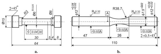
Figure 1.
Geometry of the specimens: (a) for tensile test; (b) for rotating bending fatigue test (the sizes are in mm).
The phase analysis was performed using a Bruker D8 Advance X-ray diffractometer. The Crystallography Open Database was used to determine the peak positions. The percentage content of strain-induced α′−martensite in the surface and subsurface layers was determined using DIFFRAC.DQuant V1.5 specialised software developed by Bruker (Billerica, MA, USA) [26]. The methodology is described in detail in [17]. The microstructure in the cross-section area of the cylindrical bars was observed by optical (OM, NEOPHOT 2) and scanning electron microscopy (SEM, LYRA I XMU Tescan) after polishing and etching the specimens using “Aqua regia”—a mixture of nitric acid and hydrochloric acid in a molar ratio of 1:3 (HNO3:HCl = 1:3).
2.2. Diamond Burnishing Implementation
DB is a static SCW process that causes severe SPD due to the tangential sliding friction contact between the deforming element (diamond) and the treated surface. As a result, the SI of the burnished component may be improved, which can also significantly increase the fatigue strength and wear resistance. DB kinematics are similar to those for turning (Figure 2). The basic governing factors of the DB process are the sphere radius of the diamond insert ®, burnishing force (), feed rate (f), and burnishing velocity (v). The additional factors are the number of passes (n), working scheme, and lubrication conditions. When the number of passes is more than one, two working schemes can be implemented: one-way and two-way [27]. In [28], it was justified that different DB processes can be implemented depending on the magnitudes of the main governing factors. When the goal is to achieve minimum values of the roughness height parameters, the implemented process is smoothing DB. When the goal is to introduce maximum residual compressive stresses in absolute value and maximum strain hardening, the process is hardening DB. This classification is analogous to the one made in [29] regarding the roller burnishing method, based on two processes: roller burnishing (smoothing) and deep rolling (hardening).
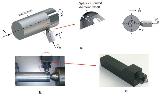
Figure 2.
DB: (a) kinematic scheme, (b) implementation on a lathe, and (c) DB device.
The experimental setup and results obtained from a parametric study of the effects of DB on steel are presented in detail in our previous study [17]. In the present study, the following values for the governing factors, obtained from [17], were used: (1) smoothing DB: radius of the polycrystalline diamond insert , burnishing force , feed rate , and burnishing velocity ; (2) hardening DB: , , , and . In [17], it was found that hardening five-pass DB significantly increases the micro-hardness and reduces the roughness parameter compared to hardening single-pass DB.
2.3. Specimen Treatment and Designation
For all the remaining tests, the specimens for the two initial states (as-received AR and initially heat-treated HT) were denoted as follows: AR1 and HT7—turned; AR2 and HT8—subjected to smoothing DB; AR3 and HT9—subjected to single-pass hardening DB; AR4 and HT10—subjected to five-pass hardening DB; AR5 and HT11—subjected to smoothing DB and then heated at 350 °C for three hours; AR6 and HT12—subjected to single-pass hardening DB and then heated at 350 °C for three hours.
2.4. Surface Integrity
The dimensions of the samples used for determining the surface integrity parameters are . The average 2D roughness parameter was measured using a Mitutoyo Surftest SJ-210 surface roughness tester. The final roughness value for each specimen was obtained as the arithmetic mean of five measurements of five generatrixes at an angle. The HV0.05 surface micro-hardness measurements were made using a ZHVµ Zwick/Roell micro-hardness tester with automated processing of the measurement results, using a load and a holding time. Twenty measurements were made for each specimen. The final value of the surface micro-hardness corresponded to the grouping centre.
A Bruker D8 Advance diffractometer with a pin-hole collimator with a primary beam measuring was used to measure the residual stresses. The X-ray tube’s mode of operation (voltage/current) was . The method with a least-squares fitting procedure evaluated the residual stresses. It was found that the change in the parameters of the DB process leads to different predominant phases in the surface and subsurface layers of samples made of AISI 304 austenitic steel, which may be either α-Fe or γ-Fe [17].
The measured diffraction profile of the α-Fe {211} plane (of the γ-Fe {220} plane, respectively) exhibits a maximum at (at for γ-Fe, respectively) for the filtered VKα radiation used. Diffraction profiles were determined using the Pearson VII method, and the lattice deformations were calculated. For the generalised Hooke’s law, the Winholtz and Cohen method with X-ray elastic constants and ( and for γ-Fe, respectively) was applied. For XRD, a 2θ range of for α-Fe ( for γ-Fe) was used, with 2θ steps of and a tilt defined by = 0, 0.1, 0.2, 0.3, 0.4, 0.5 for both positive and negative ψ angle values. The effective penetration depth of the CrKα radiation was approximately for α-Fe ( for γ-Fe).
The stress gradient under the specimen’s surface was analysed by gradually removing material surface layers by electrolytic polishing. An ATM Kristall 650 Electrolytic Polisher with electrolytes based on a solution of perchloric acid and ethanol was used to remove these layers.
2.5. Fatigue Tests
Two main groups of hourglass-shaped fatigue specimens, with minimum diameters of and lengths of 110 mm, were fabricated using a CNC T200 lathe. Figure 1b shows the detailed geometry (according to the requirements of the UBM testing machine) of hourglass-shaped fatigue specimens. The two main groups of specimens were produced according to the initial state of the 304 SS (as-received and heated at 1100 °C for one hour then quenched in water). Each of the two groups consisted of six subgroups, which were processed and labelled according to Section 2.3. The lubricant-cooler Hacut 795-H was used for both turning and DB. After turning, the samples from subgroups AR1 and HT7 were polished to meet the roughness requirements.
Rotating cantilever bending fatigue tests were conducted on a UBM testing machine. The cycle asymmetry factor is . The loading frequency was 50 Hz in air. The accuracy of counting the number of cycles to fatigue failure was 100 cycles. The rotating load magnitude and the bending moment were controlled via a lever system. The stress amplitude was calculated by the formula:
where is the bending moment, is the assigned force, is the length of the cantilever part, is the bending resistance moment of the specimen cross-section, and is the minimum diameter of the fatigue specimen. The resolution of the force is 1 N, and for the length , it is 0.1 mm. The maximum error of the stress amplitude is 2.44 MPa. For each stress amplitude, one specimen was tested to failure or until unacceptably large plastic deformation was reached, leading to automatic shutdown of the testing machine. The exceptions included samples that reached cycles (i.e., the fatigue limit), after which the test was terminated.
2.6. Corrosion Resistance
The samples were cut out from DB workpieces as shown in Figure 3. The specimen sizes were . The treatment and designation of the samples are described in Section 2.3. The electrochemical tests were performed in a three-electrode corrosion cell comprised of a platinum counter electrode, a saturated Hg/HgSO4 reference electrode, and a working electrode immersed vertically. The area of the working electrode exposed to the solution was equal to . All electrodes were immersed in 80 mL of naturally aerated 0.5 M H2SO4 at an ambient temperature. The electrochemical measurements were conducted using a potentiostat/galvanostat 263A (EG&G Princeton Applied Research) coupled with a PC by a controller. Before the measurements, the samples were allowed to stabilise under open circuit potential (OCP) for 30 min. After stabilisation, potentiodynamic polarisation curves started at a potential of about—250 mV vs. OCP up to +2000 mV vs. Hg/HgSO4 using a 1 mV.s−1 potential scan rate. The corrosion parameters (corrosion potential) and (corrosion current density) were extracted from the Tafel plots, and polarisation resistance () was determined by the Stern–Geary equation using PARCalc Tafel Analysis software. The corrosion rate (CR) was calculated according to the G102-89 standard using Equation (2):
where , ; is corrosion current density determined from the potentiodynamic curve; is the steel density; and is the steel’s equivalent weight.
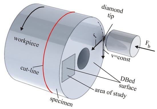
Figure 3.
Specimen for corrosion resistance testing.
2.7. Flow Chart
The flow chart of this study is depicted in Figure 4.
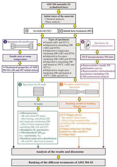
Figure 4.
Flow chart of this study.
3. Results and Discussion
3.1. Main Mechanical Characteristics
The nominal stress-nominal strain diagram is depicted in Figure 5. Table 2 shows the arithmetic mean values of the mechanical characteristics obtained from three specimens per group (as-received and quenched). The maximum deviation did not exceed 1.8%. After the initial heat treatment, the yield limit and tensile strength were significantly reduced, but the plasticity (the elongation and percentage reduction of area) increased.
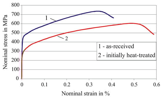
Figure 5.
Nominal stress–nominal strain diagram.
Table 2.
Main mechanical properties of the studied AISI 304 steel at room temperature (initial state).
3.2. Effect of DB and Heat Treatment on the Microstructure of 304 SS
3.2.1. Initial State of the Microstructures
The phase analysis results are shown in Figure 6. A shift of the maxima to smaller angles is observed because of the crystal lattice deformation caused by the dispersed chromium and manganese. The X-ray diffraction pattern also shows the presence of residual δ-ferrite in the as-received state.
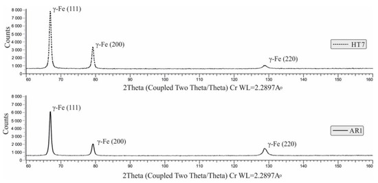
Figure 6.
Phase analysis results for 304 SS (initial states).
The microstructure in the as-received state was characterised by structural inhomogeneity (Figure 7). Zones with sliding stripes, zones with equiaxed austenitic grains with an average size of 35 μm, twin grains, and sliding zones in the grains themselves were observed. Residual δ-ferrite was observed in and around the sliding zones. These areas were likely to have an increased local chromium content. The presence of M23C6 carbide was also observed in these areas. The metal component M probably contained manganese and chromium. The presence of δ-ferrite reduced the corrosion resistance of the steel [1]. Notably, the resulting wells in the structure were a consequence of the acid treatment.
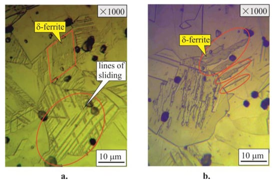
Figure 7.
Microstructure of 304 SS in the as-received state: (a) near the surface layer; (b) in the core.
After the initial heat treatment, a significant homogenisation of the structure and an increase in the size of the grains, with an average value of up to 50 μm, was observed (Figure 8). Residual inhomogeneity obtained in the manufacturing process of the bar, twinnings, and δ-ferrite decay (δ-ferrite → δ + γ) were observed only in the core of the sample (Figure 8b). The decomposition of δ-ferrite may have been the reason for the increase in corrosion resistance. To clarify the type of pits after treatment with an etching acid solution, observations were made under polarised light. Some of the particles glowed, indicating the presence of SiC or NbC (Figure 8c). The resulting pits in the structure were a consequence of the acid treatment. After the passivation of the surface layer, the development of pits was blocked.
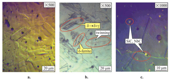
Figure 8.
Microstructure of 304 SS after initial heat treatment: (a) near the surface layer (b) in the core; (c) in the core using polarised light.
3.2.2. Effect of DB on the Microstructure Evolution
The evolution of the microstructure (as-received initial state) near the surface layer is shown in Figure 9. It is a consequence of mechanical surface treatment by turning and subsequent DB. The initial structure is a classic austenite grain shape with rectilinear slip lines and the presence of twins (Figure 9(a.1)). In the grains that contact the tool cutting wedge, distortion and thickening of the sliding lines can be observed, a consequence of partial strain hardening. The zone depth of influence from the cutting tool is approximately (Figure 9(a.1)). Near the surface layer, the segregation of carbides () can be observed along the grain boundaries (Figure 9(a.2)).
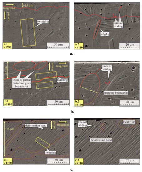
Figure 9.
Effect of DB on the microstructure evolution (as-received initial state): (a) after turning; (b) after turning and smoothing DB; and (c) after turning and single-pass hardening DB.
The zone depth of influence from smoothing DB is approximately 47 μm, which is significantly greater compared with turning (Figure 9(b.1)). The transition from a straight to curvilinear shape of the slip lines is more pronounced. A zone of partial grain boundary distortion is observed. DB causes an initial stage of grain rotation and fusion of the boundary surfaces (Figure 9(b.2)). This deformation mechanism is a preliminary stage for the formation of a deformation band.
The hardening single-pass DB caused significant structural changes at a depth of up to (Figure 9(c.1)). Complete deformation bands were observed with strongly defined straight slip lines that were parallel to each other and positioned at to the normal (Figure 9(c.2)). In the slip band, twinning was observed with slip lines that formed parallel to the elongated boundary of the twinning, which was oriented at to the normal (Figure 9(c.1)).
3.2.3. Effect of Heat Treatment after DB
Figure 10(a.1) shows a cyclogram of the thermo-mechanical treatment of 304 SS when it was in the initial heat-treated state. As described in previous work [17], the plastic deformation of 304 SS proceeds by twinning, and in the favourably oriented plastically deformed grains, the non-diffusion transformation occurs. After subsequent heat treatment, zones of tempered martensite, i.e., martensite, were observed in individual grains of the surface and near-subsurface layers (Figure 10(a.2)). This martensite is mainly distinguished from the polyhedral phase by its small size and high dislocation density. After DB and heating at 350 °C for three hours, strain ageing is possible, which is based on the time-dependent diffusion of carbon (and nitrogen) atoms into crystal defect regions (dislocations).
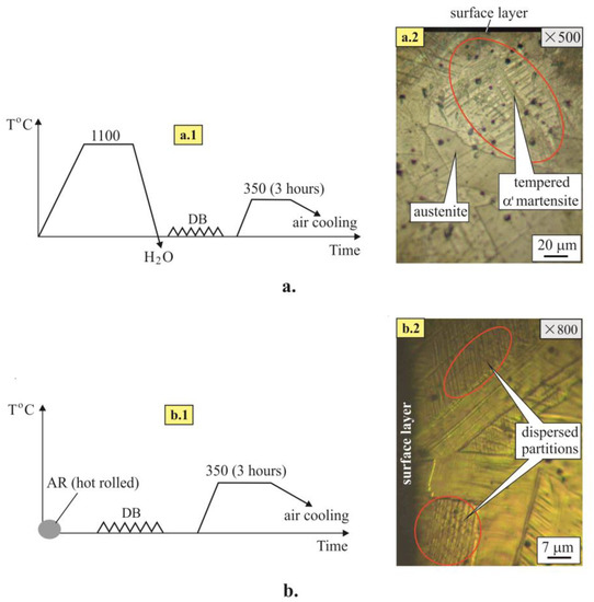
Figure 10.
Effect of heat treatment after smoothing DB on the microstructure evolution: (a) heat-treated initial state, (a.1) cyclogram, and (a.2) microstructure; (b) as-received initial state, (b.1) cyclogram, and (b.2) microstructure.
Figure 10(b.1) shows a cyclogram of the thermo-mechanical treatment of 304 SS when it is in the initial as-received state. The visible transformation of part of the plastically deformed grains in the surface layers was not detected by the metallographic method. The likely reason is the smaller plastic deformation (compared with the initial heat-treated state), which was introduced during smoothing DB because of the preliminary plastic deformation in the manufacturing process of the original workpiece (hot-rolled bar). Regardless of the absence of a visible phase transformation, DB significantly increased the density of dislocations in the surface layer, which was a sufficient reason for dynamic ageing to occur during the subsequent heating. The heating temperature (350 °C) was lower than that (400 °C) required for the secondary separation of carbide phases (). Post-DB heating caused the formation of dispersed zones (Figure 10(b.2)) that are coherently bonded to the parent matrix. These zones cause material strengthening and increase the dislocation density.
3.3. Effect of DB and Heat Treatment on the SI of 304 SS
The effects of DB and initial heat treatment on the roughness height parameter, , are shown in Figure 11. The turning after initial heat treatment (HT7) showed higher roughness () compared with the as-received state (AR1), while the trend for DB was the opposite. Both DB processes, smoothing and hardening, led to lower roughness () after initial heat treatment (HT8 and HT9), a consequence of the increased plasticity of the steel after quenching. Smoothing DB provided significantly lower roughness compared with hardening DB. Furthermore, the higher number of tool passes reduced the roughness in comparison with single-pass hardening DB.
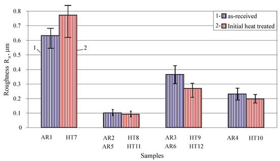
Figure 11.
Dependence of the roughness height parameter on DB and heat treatment.
The influence of DB and heat treatment on the micro-hardness is visualised in Figure 12. All DB implementations increased the surface micro-hardness compared with turning. This increase was greater for the initial heat treatment state because of the greater plasticity of 304 SS after quenching. DB caused greater plastic deformation of the surface and subsurface layers and, thus, greater strain hardening. Expectedly, the single-pass hardening DB (AR3 and HT9) led to greater micro-hardness in comparison with smoothing DB (AR2 and HT8), and this effect was more pronounced with a higher number of tool passes (AR4 and HT10). After DB, heating at 350 °C for 3 h significantly increased the micro-hardness. A greater increase was observed for single-pass hardening DB (AR6 and HT12), with the micro-hardness being significantly greater compared with five-pass hardening DB (AR4 and HT10). Therefore, when the goal is to maximise the surface micro-hardness, it is appropriate to combine single-pass hardening DB and subsequent heat treatment.
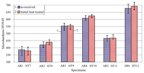
Figure 12.
Dependence of the micro-hardness on DB and heat treatment.
Figure 13 shows the influence of DB and heat treatment on the percentage content of martensite induced in the surface layer. The initial heat treatment was a prerequisite for a higher content of martensite because of the increased material plasticity. The five-pass hardening DB for the initially heat-treated state (HT10) induced 100% martensite content in the surface layer. The heating at 350 °C for three hours after DB led to partial reverse martensitic transformation.
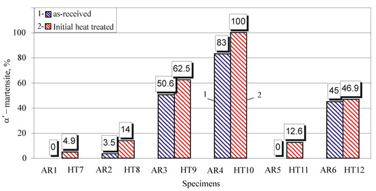
Figure 13.
Dependence of the strain-induced —martensite in the surface layer on DB and heat treatment (Note: for samples HT11, AR6, and HT12, the —martensite is tempered, i.e., transformed into —martensite).
The distributions of the residual axial stresses introduced by turning and DB are shown in Figure 14 for the two initial states: as-received and initially heat-treated. Since DB causes martensitic transformation in the surface layer (see Figure 13), the residual stresses in the surface layer and the nearby subsurface layers introduced by hardening DB were measured separately for the two phases: austenitic and martensitic. As expected, the stresses measured for the martensite phase were greater in absolute value because of the greater hardness of the martensite. Turning introduced residual tensile stresses in the surface layer, but DB introduced significant compressive stresses with a compressive zone depth of up to 0.6 mm. For both initial states, smoothing DB introduced lower residual stress in absolute value compared with hardening DB. This trend was more pronounced when 304 SS was initially heat-treated. The higher number of passes () increased the absolute residual stresses in the surface and the nearby layers for the martensitic phase when the steel was initially heat-treated. In this case (HT10), the martensite content in the surface layer was 100% (see Figure 13).
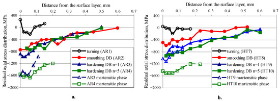
Figure 14.
Residual axial stress distribution: (a) as-received initial state and (b) heat treated at 1100 °C for one hour, then quenched in water.
Figure 15 shows the effect of heating at 350 °C for three hours after smoothing and hardening single-pass DB on the residual axial stress relaxation for the two initial states: as-received and initially heat-treated. For both initial states, the relaxation of the residual stresses introduced by smoothing DB was greatest in the surface layer, with a tendency to be more pronounced for the initially heat-treated state. At the same time, the residual stresses introduced by hardening DB and measured for the martensitic phase for this initial state did not relax. However, the residual stresses measured for the austenite phase introduced by hardening DB showed significant relaxation.
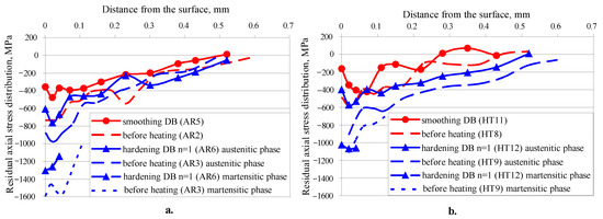
Figure 15.
Effect of heat treatment on residual axial stress relaxation of DB specimens: (a) as-received initial state and (b) heat-treated at 1100 °C for one hour, then quenched in water.
3.4. Effect of DB and Heat Treatment on Fatigue Behaviour of 304 SS
The S-N fatigue curves for the two initial states are shown in Figure 16, and -cycle fatigue strength is accepted as the fatigue limit. In general, for all treatments, the as-received state has a higher fatigue strength compared with the initially heat-treated state. The explanation for this is the initial microstructure of the steel (see Section 3.2.1). The as-received state is characterised by a finer-grain structure compared with the initially heat-treated state, as well as by the presence of carbides at the grain boundaries, which increase the strength and hardness. In addition, the steel experienced significant hot-mechanical strengthening during the production process of the as-received hot-rolled bars. Conversely, initial heat treatment increases the ductility but lowers the hardness and strength, and the grain size increases. For both initial states, DB significantly increased the fatigue strength, including the fatigue limit. For the as-received state, the fatigue limit for turned and polished specimens, accepted as a reference condition (RC1), was 440 MPa (Figure 16a). The smoothing DB, implemented as a single-pass process (AR2), increased the fatigue limit to 540 MPa, i.e., the increase compared with RC1 was 22.7%. The single-pass hardening DB (AR3) increased the fatigue limit compared with RC1 by 31.8%, from 440 to 580 MPa. The biggest increase in the fatigue limit was achieved by the five-pass hardening DB (AR4), from 440 to 605 MPa, i.e., by 37.5%. The increase in fatigue strength due to DB is greater in the high-cycle fatigue field compared with low-cycle fatigue. The likely reason for this is the higher residual stress relaxation rate in the low-cycle field that is associated with the large amplitude of the bending stresses. For the initially heat-treated state, the fatigue limit of non-DB specimens, accepted as the reference condition (RC2), is 290 MPa. The relative increases in the fatigue limit by smoothing (HT8), single-pass hardening (HT9), and five-pass hardening DB (HT10) are 17.2%, 44.8%, and 27.6%, i.e., from 290 to 340, 420, and 370 MPa, respectively. In contrast to the as-received state, the higher number of tool passes () reduces the fatigue limit compared with hardening single-pass DB, regardless of the higher compressive stresses. One of the reasons for this is that the surface and nearby layers reach a stabilised cycle in less than five passes, a consequence of cyclic loading from DB [30], i.e., a softening effect is observed for . From the point of view of fatigue limit, smoothing DB is significantly more effective for the as-received state compared with the initially heat-treated state. One of the reasons for this is the significantly higher compressive stresses introduced into the material in the as-received state (see Figure 14).
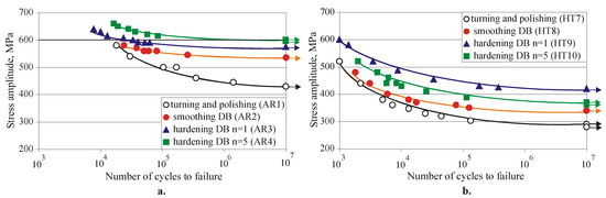
Figure 16.
S-N fatigue curves: (a) as-received initial state and (b) heat-treated at 1100 °C for one hour, then quenched in water.
The fatigue strength, and especially the fatigue limit, of the specimens subjected to smoothing DB increased (Figure 17a) for both initial states when the specimens were heated at 350 °C for three hours after SCW, despite the relaxation of the residual stresses introduced by DB (see Figure 15) and the reverse partial martensitic transformation (see Figure 13). For the as-received state, the fatigue limit increased from 540 to 580 MPa, i.e., by 7.4%, while the increase for the initially heat-treated state was 8.82%, from 340 to 370 MPa. Because of the small slope of the fatigue curves, the fatigue life increase was significant, more than 415 times greater for the as-received state and more than 571 times greater for the initially heat-treated state (see Figure 17a). A possible reason for the increased fatigue strength and fatigue life is the time-dependent diffusion-based strain ageing of the plastically deformed surface and subsurface layers affected by DB (see Section 3.2.2). The increased dislocation density due to DB was sufficient for strain ageing to occur during the subsequent heating at 350 °C for three hours, and the strain ageing led to surface layer strengthening. The movement of dislocations through the crystal was greatly hindered by the presence of small carbon atoms in the crystal flaws. Thus, the sliding resistance between the atoms increased significantly, which led to an increase in the yield strength. The hindered movement of the dislocations slowed down their clustering in a specific region along the grain boundaries. The clustering of dislocations in the boundary zone caused the formation of a focus (from which the fatigue micro-cracks originated) during cyclic fatigue. Therefore, the strain ageing increased the time it took to form a fatigue macro-crack (resulting from the coalescence of multiple micro-cracks), and, thus, increased the fatigue life. The presence of fine-grained tempered martensite (also called martensite) with high dislocation density (see Figure 10(a.2)), as well as dispersed precipitates (see Figure 10(b.2)), led to an increase in the hardness and strength, which increased the fatigue strength. Another possible reason for the increased fatigue strength of as-received hot-rolled 304 SS was the dispersion of the carbides along the grain boundary, which increased the resistance to inter-crystalline deformation.
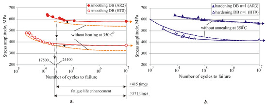
Figure 17.
The effect of the annealing at 350 °C after DB on the fatigue behaviour: (a) smoothing DB and (b) hardening single-pass DB.
However, this heat treatment after hardening single-pass DB did not significantly change the fatigue strength for either initial state of the material (Figure 17b). It is difficult to give a detailed explanation of this phenomenon because of the complexity and multifaceted nature of the ongoing processes. In summary, it can be concluded that the benefits (described above) of heating at 350 °C for three hours after hardening single-pass DB are balanced by the negative effect of residual stress relaxation and reverse transformation .
To isolate and evaluate the influence of initial heat treatment on the fatigue behaviour of 304 SS, two S-N curves of samples AR1 and HT7 (see Figure 16) were transformed into a double-logarithmic coordinate system (Figure 18) as tri-slope models using Basquin’s equation [31]:
where S is the stress amplitude used in each test and R is the number of repetitions of this stress required for rupture. It should be noted that the S-N diagram is only applicable for completely reversed stresses, i.e., the cycle asymmetry coefficient is equal to −1.
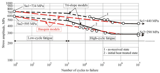
Figure 18.
The effect of the steel’s initial state on the fatigue behaviour of the non-DB specimens (AR1 and HT7).
The approximating one-slope Basquin models are straight lines in the double-log coordinate system (the red dashed lines in Figure 18). The constants C and b are expressed in Equations (4) and (5):
where is ultimate tensile strength and is the fatigue limit.
The numerical values of fatigue strength coefficient C and fatigue strength exponent b are calculated: (1) for the as-received state, and ; (2) for the initially heat-treated state, and . The larger absolute value of the fatigue strength exponent for the HT7 specimens compared with the AR1 specimens shows that the initial heat treatment of 304 SS improved the crack growth resistance, but reduced the fatigue limit, i.e., reduced crack nucleation resistance [32]. Conversely, 304 SS in the as-received state had lower crack growth resistance, but its higher fatigue limit indicated higher crack nucleation resistance.
3.5. Effect of DB and Heat Treatment on Corrosion Resistance of 304 SS
The electrochemical performance of the 304 SS in the as-received and initially heat-treated states, before and after DB, was determined by open circuit potential (OCP) measurements, followed by potentiodynamic (PD) tests. The PD polarisation curves are depicted in Figure 19, and the electrochemical parameters are shown in Table 3.
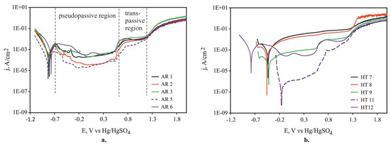
Figure 19.
Representative anodic PD polarisation curves of the samples immersed in 0.5 M H2SO4 at ambient temperature: (a) as-received initial state and (b) heat-treated initial state.
Table 3.
Representative electrochemical parameters derived from the respective polarisation curves of the samples.
The polarisation curves of all samples in the as-received state (Figure 19a) showed similar behaviour, with the formation of a pseudopassive region (from −500 up to approximately 500 mV vs. Hg/HgSO4) in the anodic part and a posterior transpassive region (800–1200 mV vs. Hg/HgSO4) around the same potentials. Similar behaviour was described in a previous report [33]. The subsequent increase in current density (corresponding to approximately ) may correlate to pitting potential. The current deflection after the transpassive region corresponds to oxygen evolution. The polarisation diagrams of the as-received specimens show that, in contrast to AR1 and AR3, the passivation current density () of the AR2 specimen was reduced over two orders of magnitude. The pits on the surface of the AR2 DB sample were characterised by smaller sizes compared with those observed on the AR1 and AR3 sample surfaces (Figure 20). The smaller percentage content of martensite in the AR2 and AR5 samples after smoothing DB, and especially after subsequent heating at 350 °C for three hours (AR5), may reduce the corrosion current density and corrosion rate (CR) compared with the turned (AR1) and DB hardening (AR3) specimens. Additionally, the lower corrosion current and CR may be related to the greatest relaxation of the residual stresses (see Figure 15), which was introduced by smoothing DB after heating at 350 °C for three hours (AR5). The lack of residual stress relaxation in the martensitic phase introduced by hardening DB after heating at 350 °C (AR6 sample) resulted in increased values of , , and CR in the AR6 sample.
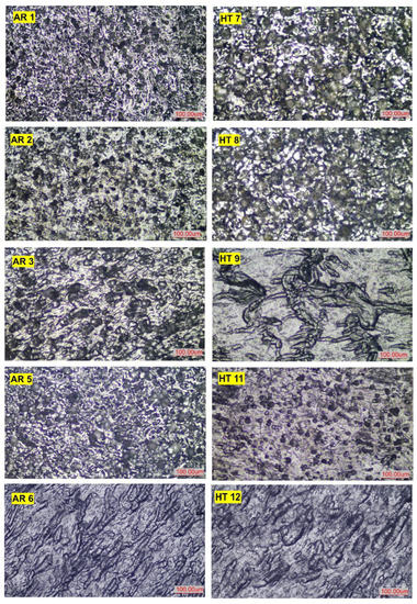
Figure 20.
Microstructural images in the corroded area of the tested 304 SS samples.
Despite significantly increasing the corrosion potential, the initially heat-treated turned sample (HT7) and smoothing DB sample (HT8) showed no passive region in their polarisation curves, meaning that the passivation process was hindered. In addition, the HT7 and HT8 samples showed a high amount of pitting with larger sizes (Figure 20) on their surfaces, indicating the susceptibility of the passive film to localised damage. These observations suggest a negative influence of these treatments on the surface corrosion resistance of 304 SS. Compared with the as-received state, the initially heat-treated 304 SS had a coarse-grained structure, which may explain this impaired corrosion behaviour. The extent of localised corrosion was relatively less for the hardening DB sample (HT9). The parallel straight bands that can be seen in the corroded surface display distinctive convex geometry in the background of an almost flat surrounding area, with small amounts of pitting (Figure 20). The former effect is reflected by the higher values of the polarisation resistance (), as shown in Table 3, suggesting enhanced general corrosion resistance. According to Liu and Frankel [34], higher compressive residual stresses can decrease the passive current density of the 2024-T3 AA alloy in 1 M NaCl. In the present study, the significantly higher compressive stresses in austenite and lower stresses introduced into martensite for the hardening DB sample (HT9) may have accelerated the reduction in and . Although it is believed that the increased surface roughness made the austenitic steel surface more susceptible to both general and pitting corrosion [35], in the present study, the HT9 sample subjected to hardening DB exhibited an anodic shift in and a decrease when compared with HT8. It is not possible to relate the increase in the surface roughness of HT9 to the higher corrosion resistance compared with HT8.
The results indicate that, for the initially heat-treated DB samples, the corrosion resistance of the surface greatly improved after subsequent heating at 350 °C for three hours. During heating, the diffusion of Cr favoured the rapid formation of a Cr-rich protective film with superior corrosion resistance [18]. However, the HT12 sample exhibited a cathodic shift , although was reduced compared with the HT7 sample. Therefore, the improved surface passivity observed after DB and heating at 350 °C cannot be connected with high-temperature oxidation alone. The small amount of martensite after smoothing DB, the lowest surface roughness, and the highest residual stress relaxation in the austenite phase after the subsequent heating at 350 °C may explain the low CR for the HT11 specimen. Some authors claim that the cathodic shift , similar to that seen in the HT12 specimen, is due to the higher fraction of martensite [19]. The severe surface plastic deformation (HT12) not only induces martensite transformation, but also causes defects, strains, and residual stresses that influence the CR. Similarly to the as-received state, the lack of residual stress relaxation in the martensite and the formation of tempered martensite with high dislocation density and dispersed precipitates may provide a large number of active sites that promote the CR in the HT12 sample (Table 3). For sample HT9, a low value of CR (second in rank for the initially heat-treated state) was obtained, regardless of the high percentage content of the volume fraction of martensite, the relatively high surface roughness, and the significant residual compressive stresses. It follows that clearly expressed correlation of the volume fraction of the martensite phase, surface roughness, and residual stresses of the samples on the corrosion behaviour of DB 304 SS specimens in 0.5 M H2SO4 was not observed. When the goal is to maximise the surface corrosion resistance, it is appropriate to combine single-pass smoothing DB and subsequent heating at 350 °C for three hours. For lowering the CR, the smoothing DB was significantly more effective for the initially heat-treated state compared with the as-received material. The consecutive impacts by quenching at 1100 °C, smoothing DB, and subsequent heating at 350 °C for three hours (HT11) had a synergistic effect on the corrosion rate of 304 SS due to the favourable complex action of many factors (microstructure, austenitic and martensitic phase ratio, plastic deformation, residual stresses, and surface topography). Figure 21 shows the effects of DB and heat treatment on the fatigue limit and CR of 304 SS. In the as-received state, smoothing DB and subsequent heat treatment simultaneously led to a high fatigue limit (equal to that obtained by hardening single-pass DB and only 20 MPa less than the maximum of 600 MPa obtained by hardening five-pass DB) and a low CR.
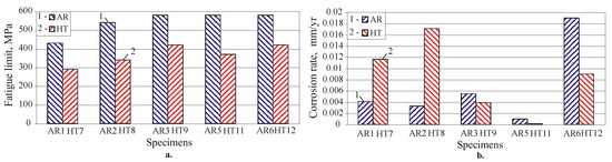
Figure 21.
Impact of DB and heat treatment on the (a) fatigue limit and (b) CR.
3.6. Integral Efficiency of DB and Heat Treatment Types of 304 Austenitic SS
A comparison of the different DB processes, in combination with heat treatments, under criteria with equal relative weights is shown in Table 4. The ranking (from 1 to 10, where 1 is the highest rank and 10 is the lowest) is based on the obtained quantitative results. The absence of first-position ranking for turned (and polished) specimens proves the necessity and usefulness of DB. A suitable manufacturing process based on DB and heat treatment can be selected from Table 3 (bold numbers) depending on the specific application of the steel component. For example, if the main requirement is for a minimum value of the roughness parameter , it is appropriate to choose option no. 9 (H11: initially heat-treated, then subject to smoothing DB and subsequent heating at 350 °C for three hours). This option is preferable to HT8 (which ensures the same minimum roughness parameter ) because it provides a negligible value of the CR. Maximum surface micro-hardness is provided by variant no. 10 (HT12), and so on. The integral efficiency of the different combined processes is shown in the last column of Table 4, and option no. 4 (AR5: as-received and subject to smoothing DB, and subsequent heating at 350 °C for three hours) has the highest ranking.
Table 4.
Comparison of the effectiveness of the types of treatments.
4. Conclusions
This article aimed to quantify the effects of different DB processes and heat treatments on the microstructure, SI, rotating bending fatigue strength, and electrochemical performance of 304 austenitic SS in two initial states: as-received and initially heat-treated. Based on the experimental results, it is possible to choose an optimal DB process and heat treatment depending on the operational purpose of the steel component. The major findings can be expressed as follows:
- For the as-received and initially heat-treated states, smoothing DB provided the lowest roughness: and , respectively. Both DB processes, smoothing and hardening, led to smaller roughness parameters for initially heat-treated samples, a consequence of the increased plasticity of the steel after quenching. The maximum surface micro-hardness was obtained after hardening DB and subsequent heating at 350 °C for three hours for both initial states 677 and 691 HV, respectively, and the micro-hardness improvement, compared with turning, was 75.4% and 82.8%, respectively.
- For all treatments, the as-received state showed a higher fatigue strength compared with the initially heat-treated state due to the finer-grained structure; the presence of carbides at the grain boundaries, which increase the strength and hardness; and the significant hot-mechanical strengthening during the production process of the as-received hot-rolled bar. The largest increase in the fatigue limit compared with turning was achieved by five-pass hardening DB: from 440 to 605 MPa, i.e., by 37.5%.
- The fatigue strength of the specimens subjected to smoothing DB significantly increased for both initial states when, after SCW, the specimens were heated at 350 °C for three hours, although relaxation of the residual stresses introduced by DB and reverse partial martensitic transformation were observed. For the as-received state, the fatigue limit increased from 540 to 580 MPa, i.e., by 7.4%, while the increase for the initial heat-treated state was 8.82%, from 340 to 370 MPa. Furthermore, the slope of the fatigue curves was small, and the fatigue life increase was significant: more than 415 times for the as-received state and more than 571 times for the initially heat-treated state A possible reason for the increased fatigue strength is the time-dependent diffusion-based strain ageing of the plastically deformed surface and subsurface layers affected by DB. Another possible reason, for the as-received initial state, is the dispersion of carbides along the grain boundary, thereby increasing the resistance to inter-crystalline deformation.
- Clearly expressed correlation of the volume fraction of the martensite phase, surface roughness, and residual stresses with the corrosion behaviour of DB 304 SS specimens in 0.5 M H2SO4 was not observed. When the goal is to maximise the surface corrosion resistance, it is appropriate to combine single-pass smoothing DB and subsequent heating at 350 °C for three hours. To minimise the CR, the smoothing DB was significantly more effective for the initially heat-treated state compared with the as-received material. The consecutive impacts by quenching at 1100 °C, smoothing DB, and subsequent heating at 350 °C for three hours (HT11) had a synergistic effect on the corrosion rate of 304 SS due to the favourable complex action of many factors (microstructure, austenitic and martensitic phases ratio, plastic deformation, residual stresses, and surface topography). For the as-received state, smoothing DB and subsequent heat treatment simultaneously led to a high fatigue limit (equal to that obtained by hardening single-pass DB) and a low CR.
- The obtained correlations between some characteristics of SI and the electrochemical corrosion behaviour of DB 304 SS specimens can be a basis for future research aimed at clearly distinguishing and evaluating the influence of individual main characteristics of SI resulting from DB on the corrosion resistance of this steel. Thus, with information on the SI of a given component, its corrosion behaviour can be predicted.
Author Contributions
Conceptualisation, J.M. and G.D.; methodology, J.M. and G.D.; software, J.M., G.D., A.A., V.D. and M.N.; validation, J.M., G.D., A.A., V.D. and M.N.; formal analysis, J.M. and G.D.; investigation, A.A., V.D., Y.A., M.N., G.D. and J.M.; resources, J.M. and G.D.; data curation, J.M. and G.D.; writing—original draft preparation, J.M., G.D. and M.N.; writing—review and editing, J.M. and G.D.; visualisation, J.M., G.D., A.A., V.D. and M.N.; supervision, J.M.; project administration, J.M. and G.D.; funding acquisition, J.M., G.D., A.A. and V.D. All authors have read and agreed to the published version of the manuscript.
Funding
This research was funded by the European Regional Development Fund within the OP “Science and Education for Smart Growth 2014–2020”, Project CoC “Smart Mechatronics, Eco- and Energy Saving Systems and Technologies”, No. BG05M2OP001-1.002-0023.
Institutional Review Board Statement
Not applicable.
Informed Consent Statement
Not applicable.
Data Availability Statement
Not applicable.
Conflicts of Interest
The authors declare no conflict of interest.
Abbreviations
| CR | corrosion rate |
| DB | diamond burnishing |
| OCP | open circuit potential |
| PD | potentiodynamic |
| RC | reference condition |
| SCW | surface cold working |
| SI | surface integrity |
| SMAT | surface mechanical attrition treatment |
| SPD | surface plastic deformation |
| SS | stainless steel(s) |
| XRD | X-ray diffraction |
References
- Rashkov, N.D. Heat Treatment of Steels; Technika: Sofia, Bulgaria, 1977. (In Bulgarian) [Google Scholar]
- Balevski, A.T. Metal Science; Technika: Sofia, Bulgaria, 1988. (In Bulgarian) [Google Scholar]
- Borgioli, F. From austenitic stainless steel to expanded austenite–S phase: Formation, characteristics and properties of an elusive metastable phase. Metals 2020, 10, 187. [Google Scholar] [CrossRef]
- Plaster, H.J. A Tribute to Benjamin Chew Tilghman. In Proceedings of the 5th International Conference on Shot Peening, Oxford, UK, 13–17 September 1993; pp. 2–9. [Google Scholar]
- Scibner, I.A. Burnishing Tool. U.S. Patent 1,171,146, 8 February 1916. [Google Scholar]
- Maximov, J.T.; Duncheva, G.V.; Amudjev, I.M.; Krumov, K.K.; Kuzmanov, T.V. A new single-roller burnishing technique decreasing roughness obtained. J. Mater. Sci. Eng. Adv. Technol. 2010, 2, 177–202. [Google Scholar]
- Chen, X.H.; Lu, J.; Lu, L.; Lu, K. Tensile properties of a nanocrystalline 316L austenitic stainless steel. Scr. Mater. 2005, 52, 1039–1044. [Google Scholar] [CrossRef]
- Ghosh, S.; Bibhanshu, N.; Suwas, S.; Chatterjee, K. Surface mechanical attrition treatment of additively manufactured 316L stainless steel yields gradient nanostructure with superior strength and ductility. Mater. Sci. Eng. A 2021, 820, 141540. [Google Scholar] [CrossRef]
- Gatey, A.M.; Hosmani, S.S.; Singh, R.P. Surface mechanical attrition treated AISI 304L steel: Role of process parameters. Surf. Eng. 2016, 32, 69–78. [Google Scholar] [CrossRef]
- Dureau, C.; Novelli, M.; Arzaghi, M.; Massion, R.; Bocher, P.; Nadot, Y.; Grosdidier, T. On the influence of ultrasonic surface mechanical attrition treatment (SMAT) on the fatigue behaviour of the 304L austenitic stainless steel. Metals 2020, 10, 100. [Google Scholar] [CrossRef]
- Azar, V.; Hashemi, B.; Yazdi, M.R. The effect of shot peening on fatigue and corrosion behaviour of 316L stainless steel in Ringer’s solution. Surf. Coat. Technol. 2010, 204, 3546–3551. [Google Scholar] [CrossRef]
- Iswanto, P.T.; Akhyar, H.; Utomo, F.F. Effect of shot peening at different Almen intensities on fatigue behaviour of AISI 304. Metalurgija 2018, 57, 295–298. [Google Scholar]
- Kakiuchi, T.; Uematsu, Y.; Hasegawa, N.; Kondoh, E. Effect of ultrasonic shot peening on high cycle fatigue behaviour in type 304 stainless steel at elevated temperature. J. Soc. Mater. Sci. Jpn. 2016, 65, 325–330. [Google Scholar] [CrossRef]
- Juijerm, P.; Altenberger, I. Fatigue performance enhancement of steels using mechanical surface treatments. J. Met. Mater. Miner. 2007, 17, 59–65. [Google Scholar]
- Moussa, N.B.; Gharbi, K.; Chaieb, I.; Fredj, N.B. Improvement of AISI 304 austenitic stainless steel low-cycle fatigue life by initial and intermitten deep rolling. Int. J. Adv. Manuf. Technol. 2019, 101, 435–449. [Google Scholar] [CrossRef]
- Maximov, J.T.; Duncheva, G.V.; Anchev, A.P.; Ganev, N.; Amudjev, I.M.; Dunchev, V.P. Effect of slide burnishing method on the surface integrity of AISI 316Ti chromium-nickel steel. J. Braz. Soc. Mech. Sci. Eng. 2018, 40, 194. [Google Scholar] [CrossRef]
- Maximov, J.T.; Duncheva, G.V.; Anchev, A.P.; Dunchev, V.P.; Argirov, Y.B. Effect of diamond burnishing on fatigue behaviour of AISI 304 chromium-nickel austenitic stainless steel. Materials 2022, 15, 4768. [Google Scholar] [CrossRef]
- Hao, Y.; Deng, B.; Zhong, C.; Jiang, Y.; Li, J. Effect of surface mechanical attrition treatment on corrosion behaviour of 316 stainless steel. J. Iron Steel Res. Int. 2009, 16, 68–72. [Google Scholar] [CrossRef]
- Balusamy, T.; Sankara Narayanan, T.S.N.; Ravichandran, K.; Park, I.S.; Lee, M.H. Influence of surface mechanical attrition treatment (SMAT) on the corrosion behaviour of AISI 304 stainless steel. Corros. Sci. 2013, 74, 332–344. [Google Scholar] [CrossRef]
- Ran, M.; Zhang, C.; Wen, L.; Zhou, H.; Zheng, W. Effect of surface mechanical attrition treatment on stainless steel corrosion. Surf. Eng. 2021, 37, 739–748. [Google Scholar] [CrossRef]
- Balusamy, T.; Kumar, S.; Sankara Narayanan, T.S.N. Effect of surface nanocrystallization on the corrosion behaviour of AISI 409 stainless steel. Corros. Sci. 2010, 52, 3826–3834. [Google Scholar] [CrossRef]
- Lu, A.Q.; Zhang, Y.; Li, Y.; Liu, G.; Zang, Q.H.; Liu, C.M. Effect of nanocrystalline and twin boundaries on corrosion behaviour of 316L stainless steel using SMAT. Acta Metall. Sin. (Engl. Lett.) 2006, 19, 183–189. [Google Scholar] [CrossRef]
- Konefal, K.; Korzynski, M.; Byczkowska, Z.; Korzynska, K. Improved corrosion resistance of stainless steel X6CrNiMoTi17-12-2 by slide diamond burnishing. J. Mater. Process. Technol. 2013, 213, 1997–2004. [Google Scholar] [CrossRef]
- Labanowski, J.; Ossowska, A. Influence of burnishing on stress corrosion cracking susceptibility of duplex steel. J. Achievemens Mater. Manuf. Eng. 2006, 19, 46–52. [Google Scholar]
- ISO 6892-1:2019; Metallic Materials—Tensile Testing—Part 1: Method of Test at Room Temperature. ISO: Geneva, Switzerland, 2019.
- DIFFRAC. DQUANT. Quantitative Analysis from Calibration to Reporting; Bruker AXS GmbH: Karlsruhe, Germany, 2018. [Google Scholar]
- Maximov, J.T.; Anchev, A.P.; Duncheva, G.V.; Ganev, N.; Selimov, K.F. Influence of the process parameters on the surface roughness, micro-hardness, and residual stresses in slide burnishing of high-strength aluminum alloys. J. Braz. Soc. Mech. Sci. Eng. 2017, 39, 3067–3078. [Google Scholar] [CrossRef]
- Maximov, J.T.; Duncheva, G.V.; Anchev, A.P.; Dunchev, V.P. Smoothing, deep or mixed diamond burnishing of low-alloy steel components–optimization procedures. J. Adv. Manuf. Technol. 2020, 106, 1917–1929. [Google Scholar] [CrossRef]
- Ecoroll Catalogue. Tools and Solutions for Metal Surface Improvement; Ecoroll Corporation Tool Technology: Milford, OH, USA, 2006. [Google Scholar]
- Maximov, J.T.; Duncheva, G.V.; Anchev, A.P.; Ganev, N.; Dunchev, V.P. Effect of cyclic hardening on fatigue performance of slide burnishing components made of low-alloy medium carbon steel. Fatigue Fract. Eng. Mater. Struct. 2019, 42, 1414–1425. [Google Scholar] [CrossRef]
- Basquin, O.H. The exponential law of endurance tests. In Proceedings of the Thirteenth Annual Meeting of American Society for Testing Materials, Atlantic City, NJ, USA, 28 June–2 July 1910; Volume X, pp. 625–630. [Google Scholar]
- Stephens, R.I.; Fatemi, A.; Stephens, R.R.; Fuchs, H.O. Metal Fatigue in Engineering; John Wiley & Sons Inc.: New York, NY, USA, 2001. [Google Scholar]
- Oguzie, E.E.; Li, J.; Liu, Y.; Chen, D.; Li, Y.; Yang, K.; Wang, F. The effect of Cu addition on the electrochemical corrosion and passivation behavior of stainless steel. Electrochim. Acta 2010, 55, 5028. [Google Scholar] [CrossRef]
- Liu, X.; Frankel, G.S. Effects of compressive stress on localized corrosion in AA2024-T3. Corros. Sci. 2006, 48, 3309–3329. [Google Scholar] [CrossRef]
- Shahryari, A.; Kamal, W.; Omanovic, S. The effect of surface roughness on the efficiency of the cyclic potentiodynamic passivation (CPP) method in the improvement of general and pitting corrosion resistance of 316LVM stainless steel. Mater. Lett. 2008, 62, 3906–3909. [Google Scholar] [CrossRef]


Disclaimer/Publisher’s Note: The statements, opinions and data contained in all publications are solely those of the individual author(s) and contributor(s) and not of MDPI and/or the editor(s). MDPI and/or the editor(s) disclaim responsibility for any injury to people or property resulting from any ideas, methods, instructions or products referred to in the content. |
© 2023 by the authors. Licensee MDPI, Basel, Switzerland. This article is an open access article distributed under the terms and conditions of the Creative Commons Attribution (CC BY) license (https://creativecommons.org/licenses/by/4.0/).