1. Introduction
Currently, there is a growing effort to expand the use of unmanned aircraft (UA) for the transport of people and goods, especially in urban areas [
1], which impose completely new and more complex operational and safety requirements on the UA itself [
2,
3]. Urban areas are characterized by a spatially limited environment with many obstacles, such as buildings, towers, power lines, and especially the occurrence of a large number of people [
1]. The limited space for movement imposes on the UA an important requirement to save dimensions as much as possible, i.e., not to increase its size unnecessarily [
4]. The movement of people, on the other hand, requires the highest possible safety level of the entire system. An example is the need to prevent injury of people from the rotating parts of the UA in the situation it gets close to them. The use of electric ducted fan (EDF) units has the potential to solve some of these issues and fulfill emerging requirements, in particular the requirements for the smallest possible dimensions and protection from rotating parts to prevent a possible collision with surrounding obstacles [
5]. The outcome is that EDF provides a number of advantages compared to propeller drives, especially for vertical take-off and landing (VTOL) UA in urban areas. The research of EDF propulsion could thus contribute to the realization of new concepts of UA operation.
The ducted fan concept has been used since the 1960s, but has not been widely used in conjunction with an electric motor. The ducted fan category includes almost any drive that uses a rotor to generate thrust, which is enclosed around the perimeter in a cover that reduces the flow of air over the upper sides of the blades [
6]. This area is already widely researched because one of the most widely used propulsion systems in manned aircraft is the ducted fan, known as the turbofan [
7]. As for EDF, it is the same concept, only the rotor is driven by an electric motor instead of a jet engine [
8]. Although the concept is well known, ducted fans equipped with an electric motor are very rarely used and they are also not fully investigated in the case of UA operation associated with low Reynolds numbers and thus different non-laminar flow characteristics. EDF propulsions main advantages include a high thrust-to-weight ratio, a high thrust-to-diameter ratio of the fan, physical protection of the fan and its surroundings, the possibility of thrust vectoring, and lower noise. The most important characteristic of a ducted fan in general, is the amount of thrust it is capable of generating for a given diameter of the fan. Compared to a propeller propulsion, a ducted fan is capable of generating up to several times more thrust with the same rotor diameter [
9]. A natural feature of a ducted fan is its cover because the cover provides protection both for the fan itself and for the surroundings. For example, when using UA that would be used to operate in a populated area, EDF would provide protection to the surrounding environment. In connection with urban traffic, the ducted fan is precisely suitable due to its dimensions, as it reaches much smaller dimensions than a propeller, because it does not unnecessarily expand the dimensions of the entire UA [
9]. If necessary, it allows for installation in the structure of the airframe of an UA, unlike the propeller, which must be in an open space outside the fuselage. The ducted fan also allows the use of thrust vectoring, which allows smooth maneuvering of VTOL aircraft while hovering [
10]. This is particularly advantageous in the case of cargo transport, when unwanted tilting of the entire UA is eliminated.
From a design point of view, EDFs offer high variability in adjusting the cover flow channel with different combinations of fan arrangements, for example: two-rotor specification, see [
11]. Possible modifications are changes in the flow channel and changes in fans, such as changing the number of blades and diameter [
12]. These modifications are made to reduce noise, reduce electrical consumption (power), and increase thrust or for the purpose of reducing the dimensions of the EDF [
13,
14,
15]. Modifications result in an increase of thrust for the same electrical input, or conversely, for the same electrical input, the EDF generates more thrust [
16]. Generally, the aim of the modifications is to generate as much thrust as possible for the smallest diameter of the fan and consumption.
Above described properties of the EDFs are defined by design parameters. The most important ones include the end clearance between the fan blades and the inner wall of the cover and the ratio of the area of the outlet opening to the fan. Furthermore, there are the power of the electric motor, the kV rating of the electric motor, the radius of the leading edge, the number of fan blades, and the diameter of the fan [
17]. These design parameters, which directly determine how the EDF structure will look, subsequently affect the performance parameters, which serve as a performance indicator of the EDF, according to which the appropriateness of its use can be determined. These include parameters such as thrust, fan revolutions per minute (RPM), electrical input (energy consumption), fan efficiency, and noise [
18].
Current studies focused on the design of EDF systems suitable for use in UA operations look, for example, at the influence of hub and tip ratio on overall performance. This study came to the interesting conclusion that with the decreasing ratio between the hub and tip, the EDF works at a higher load and heats up, but at the same time the highest thrust values are generated, and vice versa [
8]. Another study dealt with the effect of the EDF body, respectively cowling themselves on flight characteristics. These wind tunnel experiments contributed to the discovery that nose up pitch occurs in forward flight [
5]. A major disadvantage of EDFs compared to standard propeller systems is their noise, which was addressed by another study which found that the greater the number of blades corresponds to the greater the noise of the entire system. However, with a reduction in the number of blades, the overall efficiency of the propulsion decreases at the same time. This study also looked at the effect of geometry of cowling on EDF efficiency in fixed-wing aircraft. It has been found that more power is generated during take off in the case of an expanding exit nozzle. However, in the case of horizontal flight, a combination with a narrowed nozzle is more suitable, which does not cause so much resistance and the turbulence occurrence [
19]. However, no one has yet addressed the effect of the different types of cowling geometry on EDF efficiency. Therefore, the aim of this research is to create and compare different types of geometry of EDF modifications that would allow to achieve the maximum possible efficiency in real operation. Specifically, this article takes a look on the cowling geometry at its outlet section in terms of expanding or narrowing outlet area, diameter of the fan, and fans configuration.
2. Materials and Methods
The objective of the study was to determine the most suitable EDF design solution for vertical thrust generation with the criterion of obtaining the highest thrust value with the lowest possible electric consumption. For the purposes of the study, two reference EDFs propulsion units were used for comparison with the proposed EDF design modifications. The use of reference EDFs enabled to monitor the effect of the modifications on the performance parameters.
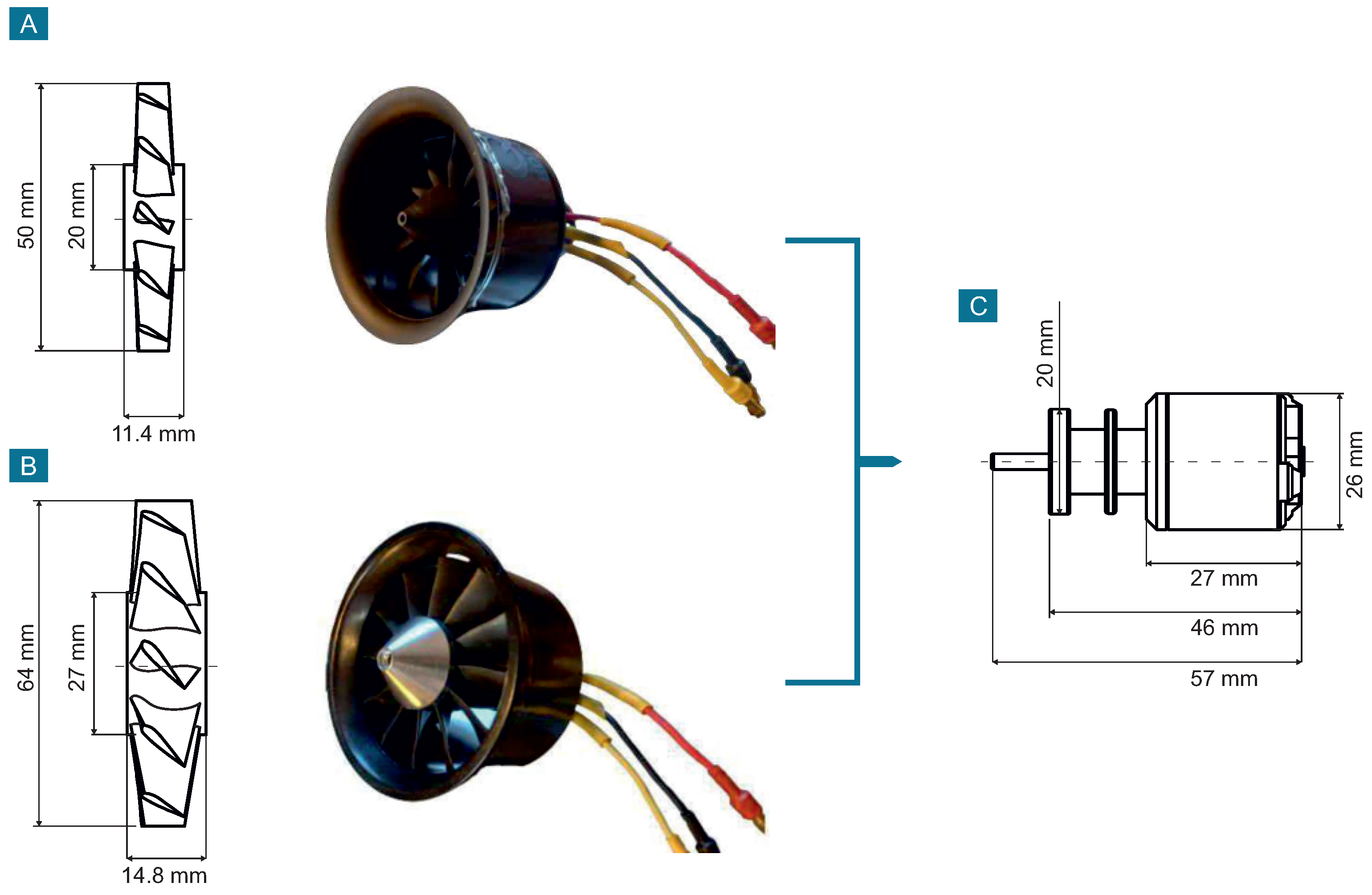
The reference EDFs were from QX-Motor (QX-Motor CO., Ltd., Kowloon, Hong Kong) with diameter of 50 mm and 64 mm, both with 12 blade fan and constant cross section of the flow channel. Both EDFs were driven by the same 5000 kV QF2611 electric motor. The EDFs were chosen mainly due to the declared maximum thrust value, which reaches up to 0.95 kgf (aprox. 9.32 N) and 5000 kV value of the supplied electric motor, allowing testing at a up to 64,000 RPM.
Figure 1 shows dimension of used fans and electric motor. Please note, for practical reasons, kilogram-force (kgf) as a unit of thrust is primarly used in this article. The relationship between units is given as 1 kgf = 9.80665 N.
The design changes included mainly the flow channel, as changes in the ratio between the outlet cross section and fan area (
). The effect of a change in this parameter was determined by theoretical calculations based on the Bernoulli equation [
20] and the continuity equation [
21] in simplified form and does not include real conditions parameters. The reason for this is complexity and lack of parameters that are related to real conditions, such as roughness of the cowling surface or pressure changes through the flow channel [
20]. However, this has no impact to the results presented below in the article as these parameters are same for all tested prototypes. Therefore, the results presented are still relevant.
In the case of EDF, the total pressure before the fan and the total pressure behind the fan are important. The total pressure before the fan (
) for static testing is [
20]:
where
is the static pressure before entering the EDF,
is the air density,
is the air velocity before entering the EDF,
is the static pressure at the location just before the fan, and
is the air velocity at the location just before the fan [
9]. Since it is a static test, the speed
, and, therefore:
The total pressure behind the fan (
) is then [
20]:
where
represents the static pressure just behind the fan. The velocity
is the same as in Equations (1) and (2). At the output of the flow channel, there is the static pressure
and velocity
. The described equations are then valid for the case of constant cross section [
9].
As mentioned, the velocity (
) of the air stream is the same immediately before and behind the fan. However, behind the fan, there is an increase in static pressure (
) due to the accumulation of air in the closed tube as the expansion of the air toward the exit is slower than the speed of the air supply by the fan. In an ideal constant flow tube, the air is no longer affected in any way and the static pressure is still the same toward the outlet. The fan thrust
is thus defined only by the increase of the static pressure behind the fan compared to the static pressure in front of the fan [
9], that is:
EDF thrust generally consists of the fan thrust
and the cowling thrust, which is the result of the adhesion forces on the cowling surfaces [
9]. Its definition is rather complicated as it depends on the parameters of the wall along which the air flows. Since the wall of the produced cowling was uneven, it would be necessary to provide computational fluid dynamics (CFD) simulations instead of calculations to find the forces related to this part of thrust [
20]. Furthermore, not all parameters required to perform realistic simulations were known. Therefore, the results would not correspond to the results obtained by the measurements. However, for the purpose of this study, calculating the cowling thrust was not needed, and its omission had no effect on the result provided in this study. Nevertheless, its existence should be mentioned.
The fan thrust is also affected by any changes to the inlet and outlet that affect the amount of static pressure. If these changes are made correctly, it is possible to get more thrust with less electric power input [
12]. A schematic representation of the individual cross sections of the EDF flow channel is shown in
Figure 2.
To determine the effect of the change in the
parameter on the static pressure, it is necessary to use the continuity equation to calculate the output velocity from the outlet (
). The equation states that the same amount of air exits the flow tube as enters it—only the ratio between the parameters of density (
), flow velocity (
v), and the cross-section of the tube (
A) changes. The product of the equation is the mass flow
[
21].
Any change in the
ratio will also change all parameters behind the fan. The increase or decrease in
will be reflected in the output air stream velocity according to the continuity equation. It is possible to completely omit the section in front of the fan from the calculations as it does not change in any way. The only affected section will be behind the fan, where the flow channel widens or narrows towards the outlet [
9,
21]. At the location just behind the fan, Section 2b, there is a certain air velocity
that was induced by the fan. The velocity at the EDF output is then
. The section behind the fan can be imagined as a separate flow channel, where the velocity at the point behind the fan is
, the inlet cross section is given by the area of the fan
and the air density
, which is the same as in the surrounding atmosphere, as the size of its change is negligible in this case [
21]. Using the continuity equation
where the left side represents the section just after the fan and the right side represents the exit section from the channel. After subsequent modification, the speed at the exit from the EDF
is obtained as
When these velocities are used in the Equation (3), the magnitude of static pressure at the EDF output (
) could be determined [
20].
The problem is that, despite knowing the
pressure, it is difficult to calculate what the resulting effect will be on the thrust of the fan and at the same time on the thrust of the entire EDF. For the calculation, it is necessary to know the pressure distribution in the entire space behind the fan, which can only be calculated numerically [
20]. However, for an accurate calculation, knowledge of the characteristics of the flow through the cowling is required, which is affected by the surface roughness, the shape of the stator blades, and the electric motor itself. Another problem are completely opposite phenomena in the case of expanding and narrowing outlet, where in the case of narrowing outlet, a gradual reduction of the static pressure toward the outlet opening and thereby decrease of the thrust are observed. With the expansion outlet, the pressure to the outlet keeps increasing, which increases the thrust of the fan [
20]. Therefore, it is necessary to determine the influence of the change in the output cross-section by experimental testing.
2.1. Design of Electric Ducted Fan Modifications
All proposals are based on the above-mentioned reference (original) EDFs, specifically
and
, which are labeled as stage 1 in
Figure 3A (note: the principle of abbreviations for the respective modifications and designs is described in
Figure 3C). All modifications mentioned bellow were made by an iterative way. The chosen values of
are not based on any previously published studies but were chosen as a reaction to the ongoing results of individual measurements performed within the testing phase. All further described prototypes used the same electric motor, which was mentioned above and is shown in
Figure 1. The reason for this decision is that if an electric motor with different dimensions were used, the area of the annulus between the outer wall of the electric motor and the inner wall of the cowling would change, causing a variation in the measured thrust.
Using the previously mentioned equations, the adjustment of the flow channel was proposed in terms of its reduction down to the value
with a fan with a diameter of 50 mm, hereinafter referred to as
. This means that the outlet cross-section has been reduced compared to the fan area, which has remained the same. If such a reduction of the
parameter occurs, it will cause an increase of the outlet air flow velocity, according to the continuity equation. Such an increase in the outlet air flow velocity will be manifested by a reduction in fan thrust, but the thrust produced by the cover itself will increase as a result of adhesion forces on the surface of the cover. A similar adjustment was also made to the 64 mm EDF marked
. Both variants are labeled as stage 2 in
Figure 3A.
Based on the results of the measurements (see chapter Results), a modification of the expanding outlet cross-section up to
with a 50 mm fan, referred to as
, was proposed. This variant reduces the velocity of the outlet air flow, which increases the static pressure behind the fan and increases the proportion of fan thrust. Thus, the exact opposite phenomenon occurs, as with the narrowing prototype. The same modification was also made for the 64 mm EDF marked
, and both variants can be seen in
Figure 3A in stage 3.
Again, based on the results, see chapter Results, additional adjustments were made to the 64 mm EDF in terms of further expanding the output. The first additional adjustment was the extension to the value
(
), which is shown in
Figure 3A in stage 4. Then, after reevaluation of the measurement results, the last adjustment with the value
(
), which is under stage 5 in
Figure 3A was proposed.
For the purpose of testing the modifications of the two-rotor specifications, a reference prototype was first designed with two 50 mm fans with 12 blades, referred as
and labelled as stage 1 in
Figure 3B. The measured values of this reference prototype served as a reference for the proposed two-rotor modifications described below. The flow channel modifications of the two-rotor specifications were produced in two variants, with an increased outlet similar to the previous ones and a variant with a separated channel. The first modification was the gradual expansion of the outlet from the first fan to the outlet, referred as
(see
Figure 3B). The front fan was 50 mm in diameter and the rear fan was enlarged to 64 mm, both with 12 blades and with overall parameter
. This prototype is based on calculations performed on single-rotor versions with expanding output, where the channel shaped in this way positively influenced the performance characteristics of the EDF.
Subsequently, based on the fact that the rear fan is negatively affected by the flow from the front fan [
22,
23], the separated channel specification marked
was produced (see
Figure 3B). The difference is that the flow channel does not expand between the fans but remains constant with a diameter corresponding to first 50 mm fan. The remaining space up to a diameter of 64 mm is then separated and forms a separate channel that leads from the inlet to the 64 mm fan. Its purpose is to supply unaffected air to the rear fan section so that it can work with higher efficiency, which is reflected in better EDF energy consumption.
Due to the lack of usable components, it was necessary to use two counterclockwise fans. It was also necessary to use fans with a high number of blades due to the absence of a fan in the 50 mm specification with a smaller number of blades. These facts have a negative effect on the measured absolute values, since contrarotating fans with a smaller number of blades [
22,
23] are more suitable constructions. However, these conditions are identical for all proposed two-rotor specifications, and for that reason, it is possible to compare them with each other and observe the effect of the flow channel adjustment. Thus, for the purposes of the study, this construction is sufficient.
It is necessary to mention that the modifications of the two-rotor arrangements are not based on any calculations. These are solutions based on theoretical knowledge [
22,
23] and experimental tests. With these constructions, it is difficult to perform calculations that would yield relevant results, as the flow between the fans is affected by many factors, and subsequently, the air entering the rear fan is also affected. Therefore, these adjustments were gradually changed on the basis of experimental measurements.
2.2. Prototypes Production
All proposed single-rotor and two-rotor specification modifications were designed using Solidworks 3D CAD modeling software (SolidWorks Corp., Waltham, MA, USA) and subsequently manufactured using 3D printing technology, specifically using FDM (fused deposition modeling) technology. It is a technology whose principle consists in creating a product by folding the material into individual layers [
24]. The advantages of this method are low time and financial requirements of production. All prototypes could be produced in the range between 3–5 h. The disadvantage is the layering of the material itself, because the surface is deteriorated by layers, which creates rough surface. In the case of the aerodynamic cover, such surface deteriorates its properties. This was also reflected in the 3D printed prototypes. During production, a layer height of 0.12 mm was used to reduce this effect as much as possible. Polyactic acid (PLA) material was used for productionas as it enables a short printing time. The disadvantage of this material is the plasticity temperature, which for PLA is around 60 °C [
24]. As the material temperature approaches this limit, the material begins to deform at a certain load value. Therefore, it was necessary to monitor the electric motor temperature as it should not reach this temperature during the testing.
Since production technology caused high surface roughness, the same production tolerances as for the purchased ones could not be maintained. Therefore, the performance parameters of the produced prototypes deteriorated. This difference had to be taken into account when evaluating the results. Therefore, these reference EDFs were also remanufactured using identical production technology, and all suggested modifications were then compared with the measured values of these redesigned versions.
2.3. Data Measuring Procedures
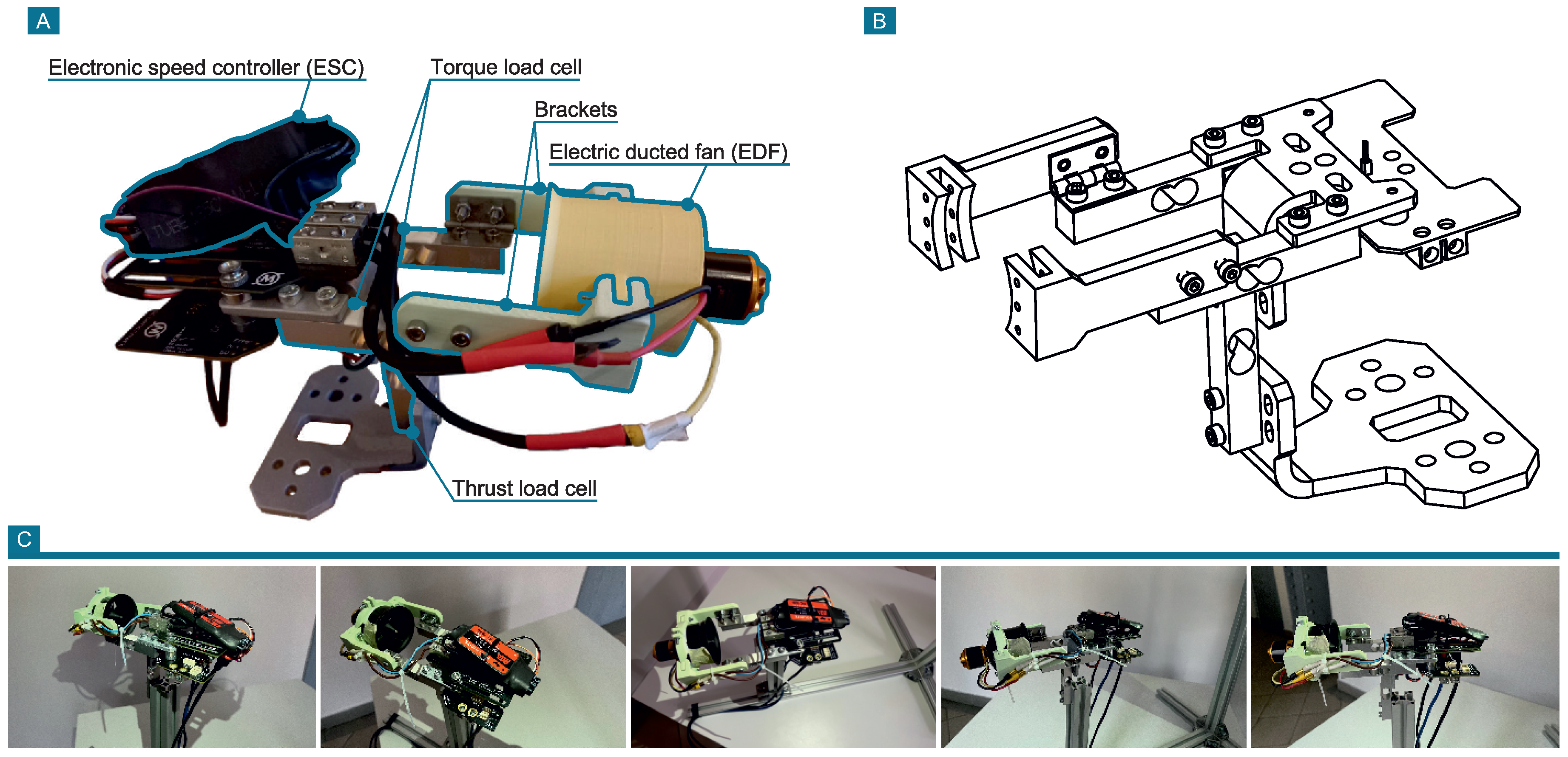
An RCbenchmark Series 1580 test stand (Tyto Robotics Inc., Gatineau, Canada) was used to measure the parameters of the designed prototypes. The stand is designed to test brushless propulsion systems, specifically for the testing of unmanned aircraft propulsion systems. The main advantage of this stand is the availability of a software interface that serves for its control. This enables both manual control of the electric motor and the use of preset or custom scripts that enables automatic measurement according to preset parameters. Several parameters are measured by the stand directly using fitted sensors, such as thrust, torque, electrical current, and vibrations. The remaining parameters are computed based on these directly measured. All measured parameters that can be obtained from the stand are listed in
Table 1, together with the accuracy. This stand is designed primarily for measuring propeller propulsion and, for that reason, it was necessary to design a new mounting brackets for the EDF to be able to use this stand. This new mounting system was designed to not change the way forces are tranferred to the strain gauges. Main change was only in the shape of mounting system to be able to hold tested EDFs, but the length and position of motor remained the same, so the strain gauge lever was not changed and accuracy of measurements remained the same. In
Figure 4, a test stand with modified attachment is shown.
The measured parameters for the purposes of this study were thrust, electrical power, and electrical current. These parameters were set to be essential to determine the influence of the design on the energy characteristics of the EDF [
25]. For testing, two procedures were established, and each prototype went through three measurements for each procedure. The first procedure was to test the prototype at a constant increase in revolutions per minute (RPM). The testing lasted 60 seconds, during which the fan speed was gradually and uniformly increased; thereby, the characteristics of the measured performance parameters over the largest possible working range of the EDF were obtained. The second procedure was the measurement of the parameters at a selected thrust value, namely the thrust value of 0.2 kgf (aprox. 1.96 N). This means that the EDF was revved to the necessary RPM, at which the given prototype generated a thrust of 0.2 kgf (aprox. 1.96 N). The motor remained at this thrust value for 60 s and the performance parameters were measured. The results of this measurement were subsequently used to compare the measured parameters of all prototypes with each other. Value of 0.2 kgf (aprox. 1.96 N) was selected based on the experimental measurements as it is a value that could be achieved during the measurements for all the prototypes tested.
One electric motor was used to test all EDF modifications. The effect of the electric itself was thus the same for all tests, and it was possible to monitor the effect of only the fan and the flow channel adjustments on all EDF performance parameters. The electric motor used was aforementioned QF2611 with 5000 kV, which was supplied together with the purchased EDFs and was specifically selected with such a high kV value to cover the largest possible RPM range for all prototypes during testing.
2.4. Data Processing
For various reasons, such as slight manufacturing inaccuracy and vibration, the measurements were accompanied by mild oscillations. Therefore, the data were smoothed using Savitzky–Golay [
26] with parameters of
and
.
The three performed measurements were then averaged and the mean values are presented. To be able to average these measurements, the replicability of the measurements has to be ensured. To determine whether the measurements are similar along repeated measurements and at the same time differentiable between each setup (EDF modification), that is, each setup provides unique and replicable results, and the principal component analysis (PCA) was applied using the singular value decomposition algorithm [
27]. The investigated datasets for both RPM and electric power consisted of 30 samples (three repeated measurements for each EDF prototype) and 20,000 variables (for thrust on interval
kgf sampled at 10 kHz).
The PCA results are then presented in the form of biplots showing scores and loadings for the first two principal components, as these explained more than 99 % of the variance in the dataset. Since the data presented in the biplots form clusters, the determination of the existence of statistically significant differences between the clusters was then based on the possible overlaps of confidence intervals by means of 95 % confidence ellipses [
28] plotted around the clusters.
The measured data were processed in the Matlab 2020b (MathWorks, Inc., Natick, MA, USA) environment using signal processing and statistical toolboxes.
3. Results
The differences in the dependence of thrust on electrical power for all tested EDFs are shown in
Figure 5. A comparison of the original EDFs and the printed prototypes with fan diameters of 50 mm and 64 mm is then shown in
Figure 5A. The figure shows that the 3D printed prototypes have worse energy characteristics compared to the purchased originals. To achieve a thrust value of 0.2 kgf (aprox. 1.96 N), the 50mm 3D printed prototype needs 37 W more power than the purchased EDF and the 64 mm prototype needs 61 W more power than the purchased EDF. Additionally, the produced prototypes achieved a lower maximum thrust value. The original EDF achieved thrust values of around 0.7 kgf (approx. 6.87 N) and the produced prototypes achieved around 0.3 kgf (approx. 2.94 N).
In
Figure 5B, the difference for the tested 50 mm 3D printed prototypes is shown. The increasing outlet diameter (
) reduced power consumption to achieve the same thrust, when 123 W was needed to achieve a thrust of 0.2 kgf (aprox. 1.96 N). On the contrary, narrowing the channel (
) toward the output increased the power consumption and a thrust of 0.2 kgf (approx. 1.96 N) was achieved with a consumption of 198 W, which is the highest consumption of all tested 50 mm prototypes. In a constant reference cross-section (
), a thrust of 0.2 kgf (approx. 1.96 N) was achieved with a power input of 135 W.
The difference in dependencies for 3D printed prototypes with a diameter of 64 mm with 12-blade fan is shown in
Figure 5C. The results show that the energy consumption decreases with the widening outlet and the consumption increases with the narrowing outlet. With an expanding output (
), the power consumption was 152 W to produce 0.2 kgf (approx. 1.96 N) thrust, which is even an increase of 4 W compared to the constant cross-section. However, with a further increase of
value, the consumption already decreases as
consumption of 140 W was measured. Such a value is already close to the difference for the modification with 50 mm diameter (
). The last modification tested (
) achieved the lowest consumption of all prototypes of 116 W. In the 64 mm specification, the narrowing channel (
) was also tested and reached the highest consumption of all prototypes, approximately 220 W for a thrust of 0.2 kgf (approx. 1.96 N).
The PCA confirms that the different EDFs show unique characteristics as the 95% confidence ellipses which are constructed around separate clusters do not overlap (see
Figure 5D). Furthermore, it is apparent that the characteristics of each EDF obtained during repeated measurements are similar, since the clusters consisting of respective scores are rather small, as are the areas of the ellipses.
Comparisons of the dependence of thrust on fan RPM for identical EDFs shown in previous figures are presented in
Figure 6. In
Figure 6A, a comparison of the original purchased EDF and 3D printed prototypes with fan diameters of 50 mm and 64 mm is shown. Printed prototypes have a worse dependence and generally need to reach a higher RPM to achieve the same thrust value. The results also show that as the diameter of the fan increases, the necessary revolutions to achieve a specific thrust value decrease. For the 50 mm 3D printed prototype, it is necessary to reach
RPM to achieve a thrust of 0.2 kgf (approx. 1.96 N), while for the 64 mm prototype, it is necessary to achieve only
RPM.
In
Figure 6B, the dependence for 50 mm prototypes is shown. There is a small change between the expanding cross-section (
) and the constant cross-section (
); the difference in speed is only 364 RPM. However, for the narrowing cross-section (
), there was a significant increase in revolutions up to the value of
RPM, which is an increase compared to the reference EDF by
RPM.
In
Figure 6C, the dependence for the 64 mm prototypes is shown. For the reference constant cross-section (
), a thrust of 0.2 kgf (approx. 1.96 N) was achieved at
RPM. For
and
, there was even an increase in the necessary revolutions by approximately 300 RPM, compared to the reference EDF. With subsequent growth of the outlet diameter (
), the required revolutions decreased to the value of
RPM.
As in the previous case, also for the fan RPM-thrust dependence, PCA confirms that each EDF is differentiable as the clusters, or rather 95% confidence ellipse around the clusters, do not overlap. This means that there is a possibility of precisely distinguishing the clusters. The compact clusters then confirm the similarity of repeated measurements for separate EDFs.
Two-Rotor Prototypes
In
Figure 7, a comparison of power characteristics for the mentioned two-rotor prototypes is shown. At a constant reference specification (
), a consumption of 204 W was measured to achieve a thrust of 0.2 kgf (approx. 1.96 N). Subsequently, a measurement was performed on the expanding modification (
), which shows a reduction in consumption over the entire measured characteristic and reaches a consumption of 198 W at a thrust of 0.2 kgf (approx. 1.96 N). The best results were achieved by the last modification with a separated channel (
), which had the lowest consumption of all two-rotor modifications tested, as at a thrust of 0.2 kgf (approx. 1.96 N) achieved a consumption of 174 W, which is a reduction of 30 W compared to the reference measurement.
4. Discussion
Obtained results show that the 3D printed prototypes reach worse values compared to the purchased originals, which is mainly due to the deteriorated surface and greater tolerances caused by the production technology. The surface of bought reference EDFs was made by plastic injection technology whitch produces high-quality finish of the surface with small roughness [
29]. This leads to much better aerodynamic properties in comparison with 3D printed prototypes, whitch has higher roughness of the surface which has negative impact to air flow through the cowling. The lower measured maximum values for the printed prototypes are due to the fact that magnitude of vibrations exceeded safe limit at higher thrust values, which could lead to damage of the test equipment and the power unit itself. For these reasons, it was necessary to use these printed reference prototypes for further comparisons between individual prototypes, instead of purchased ones, so that the individual comparisons would be relevant. The difference between the energy characteristic of 50 mm and 64 mm EDF was small, due to the fact that the electric motor used is not suitable for the larger fan diameter as it has too high kV value, which, in this case, worsens consumption [
14]. The results show that as the diameter of the fan increases, the required RPM of the fan decreases, and thus the required kV value of the electric motor used also decreases. Using a motor with a smaller kV value, the 64 mm specification would achieve better energy efficiency. The fundamental finding was that as the diameter of the fan increases, it is possible to use electric motors with a smaller kV value to obtain the greater possible thrust with the least possible energy consumption.
The results indicate that for the 50 mm EDF, increasing the outlet diameter compared to the fan diameter improves the EDF energy characteristics. In contrast, a narrowing outlet significantly worsens this characteristic. Similar results can be concluded for 64 mm EDF. The difference was only for , which had slightly worse thrust-to-power ratio, than the 64 mm prototype with . Anyway, recorded waveforms of the power characteristics are similar for both prototypes, correlation coefficient was R=0.9993. However, these characteristics were shifted in amplitude by approx. 4 W. Although PCA indicates that differences between these two specific measurement series are statistically different, this has negligible effect to power consumtion in real conditions. The reason for this difference is most likely production imperfection. Such a result is important, as it showed that there is a dependence between the diameter of the fan and the diameter of the outlet cross-section. In other words, as the diameter of the fan increases, it is also necessary to increase the diameter of the outlet opening to maintain a proportional improvement in energy performance.
The last specification was the two-rotor, which was tested in 3 prototypes. The first tested prototype () with a constant cross-section served only as a reference. The first modification proposed was a gradual expansion of the flow channel from the first 50 mm fan to the outlet with the rear 64mm fan (). The results showed that the same applies to these two-rotor specifications as in the previous one-rotor cases, i.e., expanding the flow channel improves the energy characteristics of the EDF when generating static thrust. Following theoretical knowledge on these two-rotor specifications, a prototype with a separate channel () was made to bring unaffected air to the rear fan to increase its efficiency. The modification is based on the previous expanding specification, so the first fan has a diameter of 50 mm and the rear one has a diameter of 64 mm. Such modification caused a further reduction in consumption and therefore achieved the highest energy efficiency of all three tested prototypes. It can be concluded that when generating a static thrust, it is most appropriate to use the specification with a separated channel for the two-rotor specifications because it achieved the lowest consumption.
The results described above are primarily focused on a general overview of possible design solutions for EDF propulsion systems for use on VTOL devices to create vertical thrust. This approach is different from other studies that also deal with the implementation of EDF propulsion systems for use on unmanned aircrafts. These studies were mainly concerned with one EDF design for a specific application; few examples follows. Vasanthakumar, Tsering, and Suddunuri [
30] dealt with the EDF design to reach predefined parameters and the result was one specific design. Another study conducted by Vratny and Hornung [
31] dealt with the EDF sizing consideration for hybrid energy aircraft and focused on verifying whether the ducted fan concept in conjunction with an electric motor is a suitable choice for use in aircrafts, such as replacing conventional power units. The result of the study is mainly a comparison of the size of the EDF to create thrust of the selected value compared to conventional aircraft propulsion. Jin et al. [
8] dealt with the EDF power density and electric motor cooling, to find the best design with highest power density but sufficient cooling for the used electric motor. In contrast to these studies, this article is primarily focused on a general approach to EDFs and their possible design variations. The study provides findings about relation between cowling geometry and energy consumption for generating static thrust (zero forward velocity). Findings are crucial for VTOL UA because EDFs could be used in conjunction with thrust vectoring. In this form, EDF would be situated perpendiculary to direction of flight and would generate vertical thrust. Vectoring flaps at the outlet of the cowling would control flow direction for maneuvering. This concept would allow very fine movements of UA without tilting in the way of UA movement. Elimination of tilting is huge benefit for purposes of transporting people and cargo. Knowledge of relation between cowling shape and energy consumption will be used in future studies where thrust vectoring will be implemented.
5. Conclusions
A number of single-rotor and two-rotor EDF modifications were tested to determine the effect of the EDF design on the performance parameters, specifically on electrical energy consumption at a specific thrust value. The study was carried out to verify the applicability of EDF in unmanned aircraft, especially in terms of consumption. During experimental measurements, it was found that the most suitable design for all single rotor modifications appears to be the most advantageous concept with an expanding channel, namely and . In this design, the reduction in consumption is caused by an increase in the static pressure behind the fan, which increases the amount of thrust produced at a specific value of electrical power. As for the two-rotor specifications, it was also found that the expanding flow channel towards the output reduces the consumption of the EDFs. In particular, if a separated flow channel is used to bring unaffected air to the rear fan, this increases its efficiency ().
The results allow to find the most suitable designs of EDF from the point of view of electrical consumption. Based on the findings from the study, it is possible to choose the right combination of electric motor, fan and flow channel shape to create an effective EDF propulsion unit for creating vertical thrust on unmanned aircraft. However, presented results can not be easily generalized as they are primary applicable only if similar prototype setup is used. For example, if different electric motor was used, the area covered by electric motor at the output of the cowling would change, so as the value of measured thrust. Therefore, it is necessary to have same percentage of outlet covered by electric motor as with used protototypes to be able to apply presented results. Same can be applied if fans with different parameters or stator blades would be used.
The limitations of the study are mainly in the production technology used, which significantly affected the performance parameters of the EDF. The measured data are thus burdened with bias and the maximum thrust provided by the proposed modifications is not entirely clear. This is followed by the limitations of the test stand, which has maximum continuous current at value of 40 A and it also did not allow testing the available EDFs to their maximal limits. Despite these shortcomings, the study mainly used differences between individual specifications; therefore, the presented results are relevant. It would be advantageous to design more prototypes with different setups to be able to provide results that could be generally used. It would also allow to identify and analyze another parameters that crucially influence thrust values and energy consumption.
For further research, it is necessary to perform dynamic testing when EDF is used on a specific model of an unmanned aircraft to determine the maneuverability of individual prototypes. It seems also appropriate to focus on the use of thrust vectoring, which is one of the EDF advantages and which offers a wide use of UA fitted with this thrust vectoring EDF. In future studies, it would be also convenient to use CFD, which would allow much more efficient design that would have an effect especially on absolute values. For this purpose, it would be essential to determine surface roughnes of produced cowling to get valuable results from these simulations. It would be also advisable to use additional measuring equipment as a flow and pressure gauges to measure changes of these parameters through the flow channel, which would allow more precise analysis. Such a setup would then enable a relevant comparison with the conventional propellers that are used on unmanned aircraft today.


