Article

Nodal Accuracy Improvement Technique for Linear Elements with Application to Adaptivity

Department of Civil Engineering, Tsinghua University, No.1 Qing Huan Yuan, Haidian District, Beijing 100084, China
*
Author to whom correspondence should be addressed.
Appl. Sci. 2023, 13(5), 2844; https://doi.org/10.3390/app13052844
Submission received: 4 January 2023 / Revised: 14 February 2023 / Accepted: 20 February 2023 / Published: 22 February 2023

Abstract

:
In the finite element method, the conventional linear elements have long been precluded, due to their low accuracy of nodal displacements, from the analysis of super-convergence and adaptivity via the element energy projection (EEP) technique. To overcome this problem, in this paper, a nodal accuracy improvement technique is proposed for linear elements in 1D to 3D problems. In this method, a residual nodal load vector is derived with the conventional EEP solution, and a simple back-substitution process can generate the improved nodal displacements without changing the global stiffness matrix. Subsequently, an improved EEP scheme for linear elements is proposed based on the improved nodal displacements. Finally, by using the improved EEP solution as an error estimator, a two-phased adaptive algorithm is presented. Numerical examples show that the accuracy of nodal displacements is improved from the second-order convergence to the fourth-order convergence by using the nodal accuracy improvement technique, and the EEP solutions for element interior displacements are improved from the second-order convergence to the third-order convergence by using the improved EEP scheme. Therefore, the improved EEP scheme can be effectively used as an error estimator in adaptivity analysis for linear elements, which turns out to be efficient in general and even outperforms cubic elements for singularity problems.

1. Introduction

Compared with the traditional finite element method (FEM), the adaptive finite element (FE) method can obtain an optimal FE mesh with its corresponding FE solution satisfying the user-specified error tolerances. The error estimation in the adaptive FE solutions plays a crucial role in the performance of adaptive algorithms in terms of effectiveness, efficiency and reliability. In recent years, various a posteriori error estimators for the FEM have been developed since it was first proposed by Babuška and Rheinboldt [1]. In general, these methods can fall into two categories [2], i.e., residual-based error estimators and recovery-based error estimators, of which the latter is more robust and popular [3]. For residual-based error estimators, the non-zero residuals of the FE solutions are used in the computed region or on the boundary, either explicitly [1,4] or implicitly [5]. For recovery-based error estimators, super-convergent solutions are calculated, replacing the exact solutions, to estimate the errors of FE solutions. Many representative recovery methods have been proposed [6,7,8,9,10,11,12,13,14], some of these methods rely on natural super-convergent points such as the Gauss points or Lobatto points in each element [6,7], and others do not use natural super-convergent points directly [8,9,10,11,12,13,14]. Adaptive analyses based on the above a posteriori error estimators have been developed, and in most cases, the energy norm is used to measure and control the calculated errors [15,16,17,18,19,20], though it makes less practical from an engineering perspective. The maximum norm is more stringent and straightforward than the energy norm, but for singularity problems it is more difficult to control the errors in stresses directly by maximum norm than in displacements, and therefore the maximum norm of displacements is a reasonably more appropriate choice [21,22], which is the choice and highlight of this paper.
It is noted that most recovery-based error estimators focus on achieving better stress solutions [6,7,8,9,10,11,12,13,14]. Although some of these methods can also be used for recovering displacements with better accuracy, the recovered displacements for linear elements using the above methods are no longer super-convergent [11,22,23]. It seems that the second-order convergence accuracy of interior displacements is the best accuracy that can be achieved for linear elements due to the constraint of second-order accuracy of nodal displacements [24,25]. It is widely accepted that the error estimations of using super-convergent solutions are reliable theoretically in recovery-based methods. Therefore, the linear elements have long been precluded from the adaptive FEM, especially using maximum norm to control errors of displacements, since both the FE and recovery solutions gain the same convergence order [22].
In recent years, a novel recovery-based technique named the Element Energy Projection (EEP) method was proposed by Yuan, etc. [11], which achieves point-wise convergence at least one order higher than the corresponding FE solutions for elements of degree m (>1) and hence serves as a reliable error estimator for adaptive FE analyses. As a result, the EEP technique has been successfully applied to a series of adaptive FE analyses in the maximum norm for a variety of problems [21,22,26]. Again, the most commonly used linear elements have been precluded from both the EEP method and the EEP-based adaptivity analyses [21,22] for the same reason that the second-ordered nodal accuracy of linear elements for 1D to 3D problems prevents super-convergence from being achieved over the original linear elements.
This article aims to overcome the aforementioned difficulties and obstacles for linear elements by proposing a nodal accuracy improvement technique. In this method, a residual nodal load vector is derived based on the computed EEP solution from the conventional FE analysis and then, without changing the FE meshes and the global stiffness matrices, a simple back-substitution process generates a correction term for nodal displacements, which enables an improved EEP solution to gain the fourth-order super-convergence for nodal displacements and third-order super-convergent interior displacements for all 1D to 3D linear elements. It is noted that, among the 1D to 3D problems, it is more difficult for the 2D and 3D linear elements focused on in this paper to achieve such super-convergent displacements. With the improved EEP solution obtained as a reliable error estimator, an effective and reliable adaptive FE solution strategy, which requires the maximum error of the FE displacements to satisfy user-specified error tolerances, is proposed for linear elements. This strategy changes the unfavorable situation that linear elements have long been excluded from the EEP-based adaptive finite element analysis, whose efficiency turns out to be even superior to cubic elements for singularity problems.
The remainder of this paper is organized as follows: Section 2 briefly describes some mature theories which will be used in this paper. Section 3 proposes the theory of the nodal accuracy improvement technique for multidimensional problems. In Section 4, the adaptivity strategy based on EEP is further improved to make it suitable for linear elements. In Section 5, the theories proposed in Section 3 and Section 4 are verified by representative numerical results. Some conclusions are given in Section 6.

2. Basic Theory

2.1. Finite Element Method

This paper will cover one-dimensional (1D), two-dimensional (2D) and three-dimensional (3D) problems. For simplicity, this section considers the following 2D partial differential equation (PDE):
{ L u 2 u = f in Ω u = u ¯       on Γ D u / n = u ¯ n on Γ N
where Ω is a bounded 2D domain, Γ D its Dirichlet boundary and Γ N its Neumann boundary with n being its outer normal direction. u ¯ and u ¯ n are known functions on the corresponding boundary.
The weak form of problem (1) is to find u in H E 1 ( Ω ) such that
a ( u , v ) = ( f , v )       v H E 1
where H E 1 ( Ω ) is the Hilbert space on Ω with its functions satisfying the essential boundary condition (BC) on Γ D and
a ( u , v ) =   Ω ( u x v x + u y v y )   d A ,      ( f , v ) =   Ω f   v   d A
Here, and below, (   ) x = (   ) / x , (   ) y = (   ) / y . Let u h denote the FE approximation to the exact solution u . Quadrilateral linear elements are adopted in this paper, and the trial function u h on each element is modeled by
u h = i = 1 2 j = 1 2 N i ( ξ ) N j ( η ) d i j
where N i and N j are usual linear shape functions in local coordinates ξ ,   η [ 1 ,   1 ] , and d i j is the associated element nodal displacements. Let S h denote the usual FE trial space (also the test space) of linear functions. Then, the FE solution u h S h H E 1 is obtained by
a ( u h , v h ) = ( f , v h ) ,     v h S h
From the arbitrariness of v h , the matrix stiffness equation of the following form can be derived as follows:
K   D = P
where K is the global stiffness matrix, P the nodal load vector and D the nodal displacement vector. Let e i , max h denote the maximum error of nodal displacements between the exact nodal displacement u i and its FE solution u i h , i.e., e i , max h = max | u i u i h | . Let e max h denote the maximum error of the FE solution u h on the whole domain, i.e., e max h = max Ω | u u h | . The mathematical analysis has shown that nodal displacements u i h achieve convergence O ( h 2 ) in maximum norm, which is the same convergence order as interior displacement u h [25].

2.2. Element Energy Projection Recovery Strategy

The basic assumption of the EEP method is that the projection theorem, i.e., a ( e h , v h ) = 0 , v h S h , holds almost true within each individual element. For 1D problems, it is mathematically proved that the neglected error for the element projection is of O ( h 2 m ) using elements of degree m . For multidimensional problems, a semi-discrete method named the finite element method of lines (FEMOL) [27] is used as a bridge between 1D and 2D problems. Taking problem (1) as the model problem, the difference between FEMOL and FEM is that FEMOL is a semi-discrete numerical method, and thus the full discretization in Equation (4) is replaced by a corresponding FEMOL semi-discrete expression
u h ( ξ , η ) = ι = 1 2 N i ( ξ ) d i ( η ) = N ( ξ ) d ( η ) e
which, by using energy variational means, leads to the following ordinary differential equations (ODEs) of FEMOL:
{ L d ( A d + B d ) + B T d + C d = F , η ( 1 ,   1 ) with BCs
Then, the FEM is used again to solve the above FEMOL ODEs by assuming that
d ( η ) e = j = 1 2 N j ( η ) d j e
The two-step discretization process of Equations (7) and (9) is equivalent to the full discretization process of Equation (4), and the same matrix stiffness equation as Equation (6) can be derived. Then, the algorithm for 2D EEP super-convergent solutions, which is also called Global D-by-D recovery strategy (EEP-G), can be achieved by two generalized 1D recovery processes as shown schematically in Figure 1.
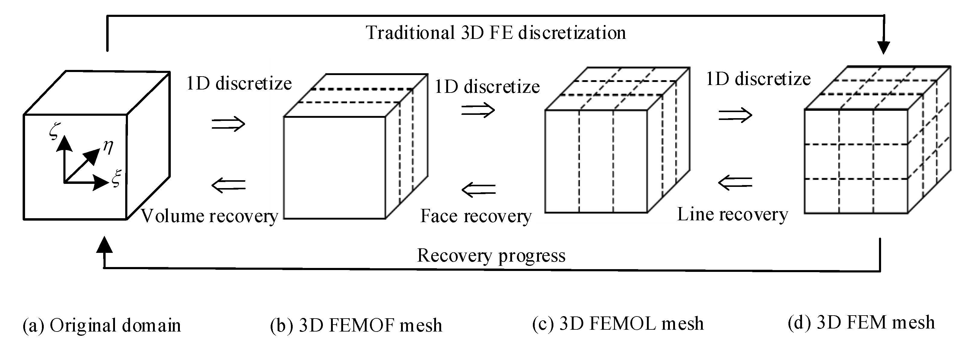
Similar to 2D problems, the finite element method of faces (FEMOF) is used as a bridge between 2D and 3D problems, then the Global D-by-D recovery strategy can be used to calculate super-convergent solutions of 3D problems. Discretization and recovery processes for 3D problems are schematically shown in Figure 2.
In recent years, more detailed work has been carried out on the super-convergence algorithm of 2D EEP, and an element D-by-D recovery strategy (EEP-E) was proposed [22], which includes four recovery steps: side node recovery, side recovery, internal side recovery and element recovery, as shown in Figure 3.
Compared with EEP-G, EEP-E gains similar recovery results but is implemented almost on a single element, which leads to less computation and more flexible FE meshes, such as local refinement, for recovery and adaptivity progresses.
Let (   ) h and (   ) * denote the FE solution and EEP solution, respectively. Let e max * denote the maximum errors of interior EEP displacement u * , i.e., e max * = max Ω | u u * | . It is worth noting that the super-convergent solution u * does not change the FE solution u h at corner nodes, i.e., u i h = u i * at element corners, and hence the super-convergence in u * is achieved based on the super-convergent nodal values. In other words, the super-convergence order of u * cannot exceed the convergence order of the FE nodal solution u i h . Therefore, although the EEP displacement u * is super-convergent compared to the FE displacement u h for elements of degree m > 1 , the EEP displacement u * for linear elements can only achieve convergence O ( h 2 ) due to its second-order accuracy of nodal displacements.

3. Nodal Accuracy Improvement Technology for Linear Elements

3.1. Nodal Accuracy Improvement for 1D Problems

It is observed that it is the second-order convergence accuracy of u i h that restricts the higher accuracy of u * for linear elements. In order to get rid of the restriction, higher accuracy of nodal displacements should be sought [28].
For 1D problems, consider the following problem:
{ L u ( p u ) + q u = f , 0 < x < 1 u ( 0 ) = u ¯ 0 ,     u ( 1 ) = u ¯ 1
After the FE solution u h and EEP solution u * of problem (10) are obtained, the error e * = u u * of the EEP solution u * is substituted back to problem (10), leading to the following supplementary problem:
{ L e * = f L u * , 0 < x < 1 e * ( 0 ) = 0 , e * ( 1 ) = 0
Then, the FE solution ε h to problem (11) is solved by using the same FE mesh and trial space as used when solving problem (10). It is noted that, in the process of FE solution to problem (10) and problem (11), the global stiffness matrix K does not change. Therefore, after the equivalent nodal load vector δ P (also called residual nodal load vector) of problem (11) is calculated, a simple back-substitution process produces the nodal increment displacement vector δ D as shown in the following form:
δ D = K 1 δ P
Since neither K nor K 1 change, the cost of obtaining a nodal increment solution δ D is much less than a full FE analysis. For 1D problems, numerous numerical experiments show that the improved nodal displacement D + δ D achieves super-convergence O ( h 4 ) , which doubles the original O ( h 2 ) .

3.2. Nodal Accuracy Improvement for 2D and 3D Problems

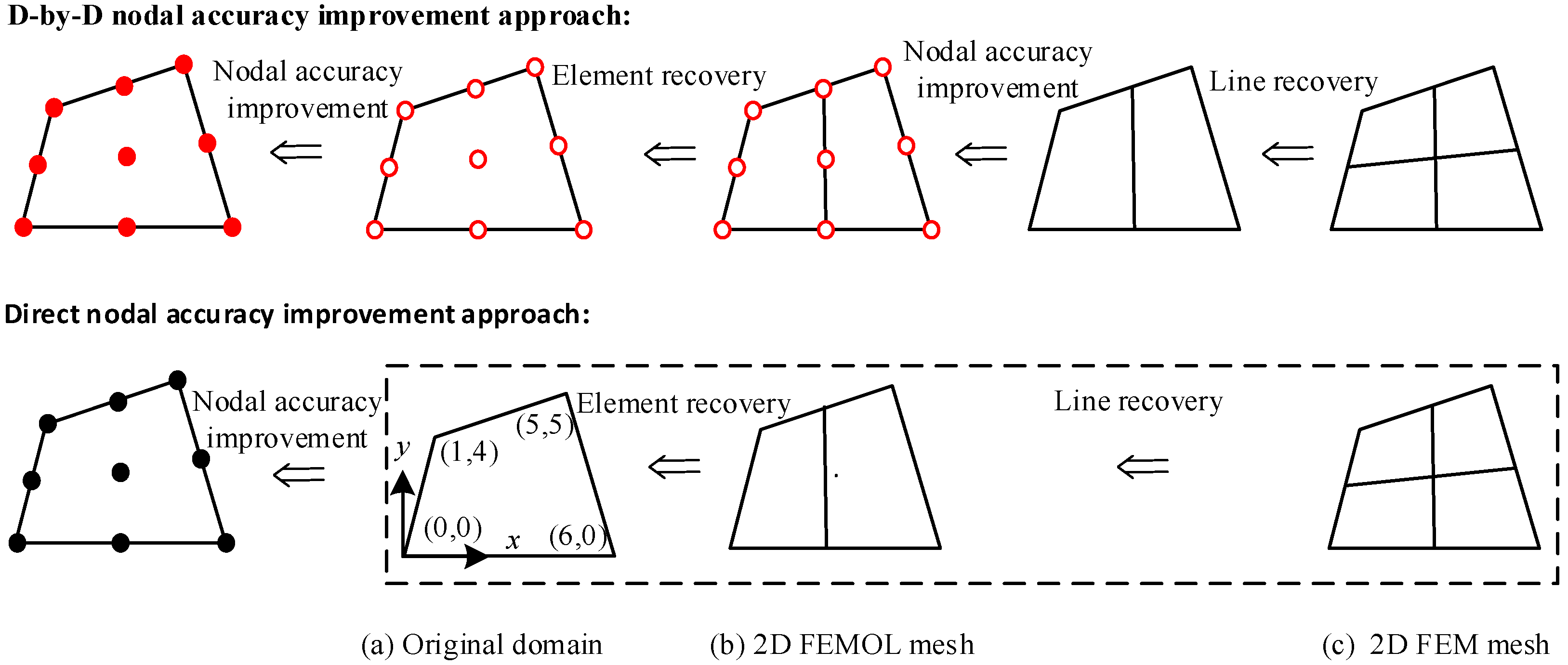
For multidimensional problems, the implementation of the nodal accuracy improvement process, as shown in Figure 4, faces a dilemma of choosing between the D-by-D approach and the direct approach, which are equivalent in the FE discretization phase but only the D-by-D approach is feasible for EEP recovery calculations in the postprocessing phase. This subsection presents a study of this issue and makes a reasonable choice.
To avoid unnecessary complications, 2D problems are to be the working case in the following, and the conclusion for 3D problems follows in a similar fashion. The two approaches are briefly described as follows.
(i)
D-by-D nodal accuracy improvement approach
In the D-by-D approach, like the EEP recovery process, the nodal accuracy improvement is carried out at two stages for 2D problems (and three stages for 3D problems) as shown in Figure 4, and can be briefly summarized schematically as follows:
  • (a) After the line recovery has finished (c.f. Figure 1 and Section 2.2), and before the element recovery, a supplementary problem similar to Equation (11) can be derived for the ODEs of FEMOL (c.f. Equation (8)) and is then solved by using the same FE mesh and trial space used in solving Equation (8) for an improved nodal solution and better FE and EEP solutions on the “mesh lines”.
  • (b) After element recovery has finished (c.f. Figure 1 and Section 2.2), another supplementary problem can be derived for the PDE in Equation (1). As before, this additional problem will be solved for using the same FE mesh and trial space used when solving problem (1) for an improved nodal solution for the original PDE problem (1).
(ii)
Direct nodal accuracy improvement approach
In the direct approach, skipping the first stage (i.e., step (a)) in the D-by-D approach, the nodal accuracy improvement process is carried out with one stroke for both 2D and 3D problems and is described as follows.
After the standard D-by-D EEP calculation has finished for the PDE problem (1), a supplementary problem can be derived for the PDE problem (1) as follows:
{ L e * = f L u * in Ω e * = 0   on Γ D e * / n = 0 on Γ N
which is solved by using the same FE mesh and trial space as used in solving problem (1) and hence is reduced to a back-substitution process similar to Equation (12). It is seen that the direct approach is very simple and straightforward and the supplementary problem in Equation (13) is also directly applicable to 3D problems.
In order to demonstrate the improvement effect of nodal accuracy intuitively, define a test problem on an irregular domain Ω as shown in Figure 4a with homogeneous Dirichlet boundary condition on all boundaries, and set the exact solution to be
{ u = cos ( π   α 2 ) cos ( π   β 2 ) α = y 3 5 + x 6 + 4 y 2 120 y + 4 x y + 576 + 48 x + x 2 6 β = x 9 + 2 y 9 + 5 3 4 y 2 120 y + 4 x y + 576 + 48 x + x 2 9
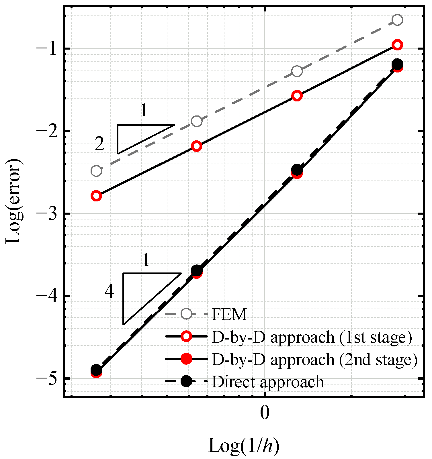
Using uniform mesh of 2 × 2 (Figure 4c), 4 × 4 , 8 × 8 and 16 × 16 elements, the maximum errors of nodal displacements among all the nodes are calculated for the FE solution, and the improved solutions of both approaches are shown in Figure 5, where the element size parameter h is taken to be the bottom side length of the bottom elements. Note that all of the computations are conducted on the same mesh by using the same linear elements. It is seen from Figure 5 that for linear elements, nodal displacements of FEM only achieve convergence O ( h 2 ) . In the D-by-D approach, the first stage of the nodal accuracy improvement only slightly lowers the nodal errors but does not raise the convergence order at all, and only after the second stage of nodal improvement does the nodal accuracy gain convergence O ( h 4 ) , which is reasonable because the first stage of nodal improvement only improves the nodal solutions for problem (8), while the overall accuracy is limited by the linear discretization error between “mesh lines” of FEMOL for problem (1). However, in the direct approach, the accuracy of the improved nodal displacements achieves convergence O ( h 4 ) once for all and is comparable to that of the two-staged D-by-D approach.
Based on the above analysis and numerical experiments, it is evident that the direct approach is the choice for practical use due to its high performance in accuracy, simplicity and generality in formulation and computation for one- and multidimensional problems. In the following, the direct approach is designated as the exclusive nodal accuracy improvement strategy.

3.3. Super-Convergent Schemes

The increment solution ε h obtained in Section 3.1 can be used to improve either the FE solution u h or the EEP solution u * , which lead to two EEP recovery schemes:
(i)
For the improved FE solution u ˜ h = u h + ε h , the EEP recovery strategy described in Section 2.2 is used to obtain the super-convergent solution of u ˜ h , which is noted by u ˜ h * .
(ii)
For the improved EEP solution u ˜ * = u * + ε h , it is found that u ˜ * itself is super-convergent over the FE solution u h directly.
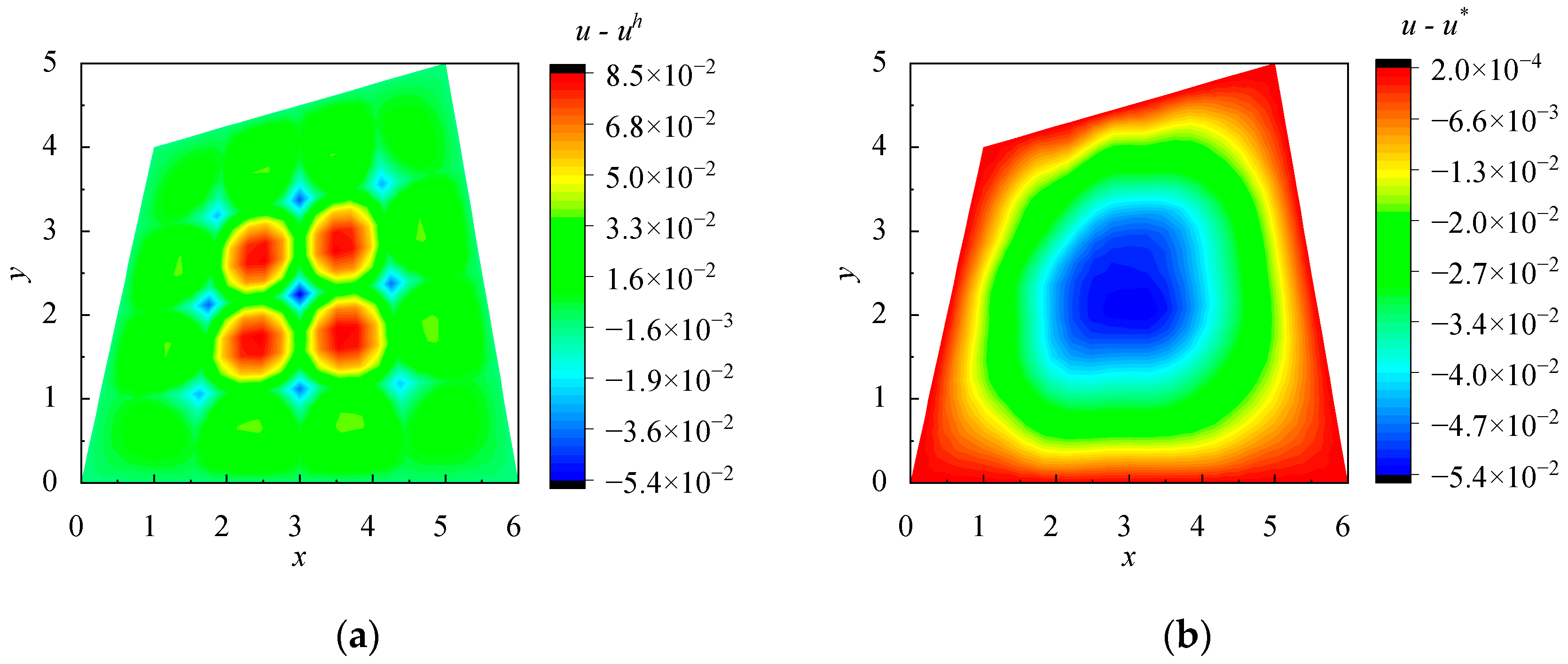
Note that all the solutions, u ˜ h , u ˜ h * and u ˜ * , have the same nodal values. To compare the above two EEP super-convergence schemes, the Poisson problem in Section 3.1 is calculated using a 4 × 4 uniform mesh. Error distributions of the FE solution u h , the original EEP solution u * , the improved FE solution u ˜ h , the EEP solution of the improved FE solution u ˜ h * and the improved EEP solution u ˜ * are shown in Figure 6.
Comparing Figure 6a with Figure 6b, it is seen that the EEP solution u * reduces the errors on elements but the nodal errors remain the same, which is around 5.4 × 10 2 in this example. Comparing Figure 6a with Figure 6c, it is seen that the improved FE solution u ˜ h reduces the nodal errors of u h with the whole error range (around 1.3 × 10 1 ) being shifted up, but the extent of the error range remains same. Comparing Figure 6d with Figure 6e, it is obvious that both the EEP solution u ˜ h * and the improved EEP solution u ˜ * have the same error range, which is much narrower than that from the original EEP solution u * . Although both u ˜ h * and u ˜ * from the two EEP recovery schemes appear to be the same in rendering accuracy, it is noted that the first one needs extra EEP recovery progress. It is also argued that the fundamental reason for improving FE nodal accuracy is to improve the accuracy of EEP solution u * rather than the FE solution u h itself. Thus, given the above analysis and arguments, the second scheme, as simple as a direct and straightforward superposition u ˜ * = u * + ε h , provides a perfect and ideal improved EEP solution for linear elements, which is exclusively employed in the following paper.
Let e ˜ i , max h and e ˜ max * denote the maximum errors of nodal displacement u ˜ i h and interior displacement u ˜ * , respectively. For linear elements, Section 5.1 and Section 5.2 will numerically verify that the improved nodal displacements u ˜ i h achieve convergence O ( h 4 ) , and the accuracy of the improved EEP displacements u ˜ * is improved from O ( h 2 ) to O ( h 3 ) , which is qualified to serve as an error estimator for FE solution u h .

4. Self-Adaptive Algorithm

The objective of the self-adaptive FE analysis of this paper is to find an optimal mesh π , such that the linear FE solution obtained on π satisfies the user-specified tolerance T l in the maximum norm of displacements on each element e :
max e | u u h | T l
Since the exact solution u is generally unknown, the super-convergent u ˜ * is used to replace u for the error checking, and the stopping criterion in Equation (15) is replaced in practical implementation by the following
max e | u ˜ * u h | T l
Numerous numerical experiments show that satisfaction of Equation (16) would indeed also make Equation (15) satisfied. Note that the present paper employed the more stringent maximum norm rather than the more commonly used energy norm used in most adaptive analyses.
Since the calculation of u ˜ * involves an additional process for nodal accuracy improvement, to save computational cost and to make the algorithm more efficient, the goal in Equation (16) is achieved by two phases in practical computation:
(1)
Find a mesh π * such that the linear FE solution u h on π * satisfies
max e | u * u h | T l
(2)
Further refine the mesh π * if necessary to find an optimal mesh π , such that the linear FE solution u h on π satisfies Equation (16).
More often than not, the first phase, without any nodal accurancy improvement involved, is able to render an almost optimal mesh π *   ( = π ) with the obtained FE solution u h on π * not only already satisfying Equation (17) but also Equation (16), and the subsequent second phase mostly serves as a post checker and safeguard.
In the above adaptive FE progress, any element for which Equation (17) or (16) is not satisfied is to be subdivided uniformly into two sub-elements for 1D problems and four sub-elements for 2D problems; for more details please refer to Yuan’s work [21] and Dong’s work [22]. For 3D problems, a local adaptive algorithm based on the EEP technique remains to be developed and is not covered in this paper. Specific adaptive examples will be shown in the following section.

5. Numerical Examples

In this section, the first two subsections, i.e., Section 5.1, Section 5.2 and Section 5.3, are dedicated to verifying the convergence orders of the FE solution u h , EEP solution u * , improved FE solution u ˜ h and improved EEP solution u ˜ * based on the linear element results on a sequence of uniformly refined meshes. The maximum norm on the domain Ω is adopted, and on each element, 10 grid points for 1D problems, 10 × 10 grid points for 2D problems and 10 × 10 × 10 grid points for 3D problems are taken as sampling points for calculating the errors of interior displacements. Effective index θ is defined as the ratio of the estimated error value to the real error value [16]. For an effective error estimator, it is expected that the value of θ tends to 1 as the mesh refines, as θ > 1 means overestimation of the error and θ < 1 means underestimation of the error.
For the subsequent three subsections, i.e., Section 5.4, Section 5.5 and Section 5.6, three representative examples of the adaptive FE analyses based on the adaptive algorithm proposed in Section 4 are presented. For comparison, the results from the uniform mesh refinement of linear elements and the adaptive mesh refinement of cubic elements [22] are also included, and the total number of degrees of freedom (DOFs), which is denoted by N dof , is counted to evaluate their performance on the final mesh.
In adaptivity examples, to facilitate the pointwise error estimation and checking, the error ratio, i.e., the error divided by the given tolerance T l , is used to normalize the error expressions so that the adaptivity criterion in Equation (15) and stopping criterion in Equation (16) can be equivalently rewritten as
1 < ( u u h ) / T l < 1     on   Ω
1 < ( u ˜ * u h ) / T l < 1     on   Ω
Therefore, as long as the pointwise error ratios ( u u h ) / T l are bounded by [ 1 ,   1 ] , the adaptivity analysis achieves full success.

5.1. Two-Point Boundary Value Problem

Consider the following two-point boundary value problem:
{ L u ( p u ) + r u + q u = f , 0 < x < 1 u ( 0 ) = 0 , u ( 1 ) = 0
where p = 1 , q = 1 , r = 10 and f = 1 . The errors of nodal displacements e i , max h , e ˜ i , max h and errors of interior displacements e max h , e max * , e ˜ max * on a series of uniform meshes are presented in Table 1, where their convergence orders are denoted by ρ . From the results, it is observed that the nodal displacements have been improved from O ( h 2 ) to O ( h 4 ) , and the accuracy of EEP displacements has also been improved, as expected, from O ( h 2 ) to O ( h 3 ) .
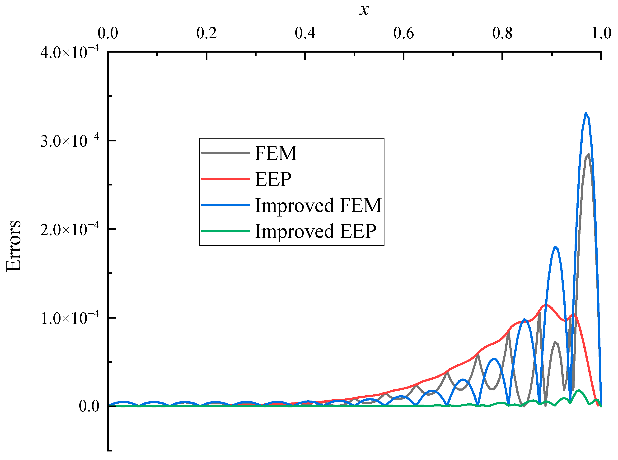
To intuitively show the errors of the various solutions, error distributions of the above results are presented in Figure 7 for N e = 16 . As can be seen from Figure 7, firstly, since both nodal displacements of FEM and EEP are equal, the error distribution curve of the EEP solution is close to that of FEM; secondly, although the nodal displacements of the improved FEM do improve the accuracy of FE nodal displacements, the maximum errors of the interior displacement on each element remain roughly the same; finally, the errors of the improved EEP displacements are much smaller than those of the FEM and EEP solutions, which is numerically verified to be super-convergent.

5.2. Elastic Plane Stress Problem

Consider the following problem with the homogeneous Dirichlet boundary condition on all boundaries.
L u ( S T D S ) u = f 1 x 1 1 y 1
where u contains two displacement components, u and v , corresponding to the displacements in the x and y directions, respectively. S is the strain matrix, D the elastic matrix and f is given in terms of the given solution u as follows:
S = [ x 0 0 y y x ] ,   D = E 1 ν 2 [ 1 ν 0 ν 1 0 0 0 1 ν 2 ] ,   f = { f x f y } ,   u = { u v } = { cos 3 π x 2 cos 3 π y 2 cos π x 2 cos π y 2 }
For brevity, set Young’s modulus of elasticity E = 1 and Poisson’s ratio ν = 0.3 . Errors of nodal displacements, e i , max h , e ˜ i , max h , and errors of interior displacements, e max h , e max * , e ˜ max * , are presented in Table 2 and Table 3, from which similar conclusions to those in Section 5.1 can be obtained. The effective index for this example is shown in Figure 8 in two component directions, and it is clear that the effective index of the EEP does not converge to unity, whereas the one of the improved EEP converges to unity rapidly.

5.3. The 3D Poisson Problem

The 3D Poisson problem considered in this example is defined as follows:
L u 2 u = f     in Ω
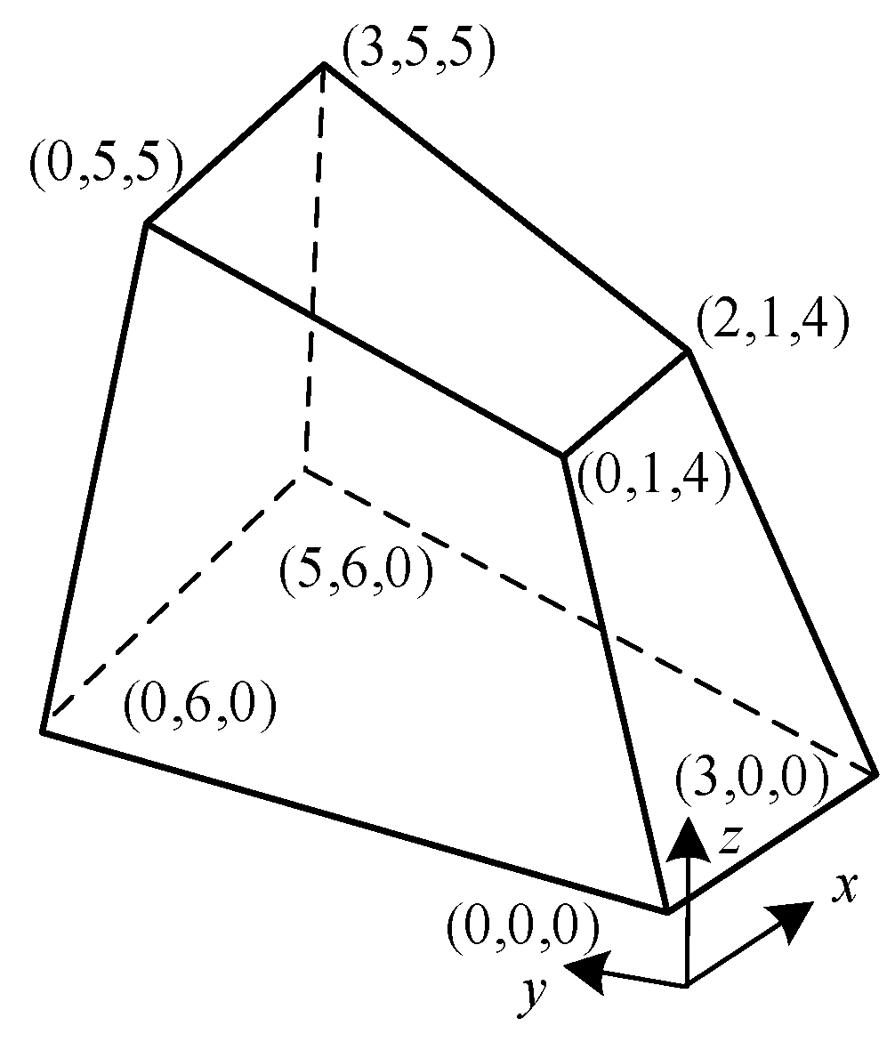
where the domain Ω is an irregular hexahedron as shown in Figure 9 with a homogeneous Dirichlet boundary condition on all boundaries. The function f is chosen so that the exact solution is of the form
{ u = cos ( π a / 2 ) cos ( π b / 2 ) cos ( π b / 2 )      a = 3 x / ( 9 + y z ) b = ( y + 2 z 30 + y 2 + 4 y z + 4 z 2 + 48 y 120 z + 576 / 6 c = ( y + 2 z + 15 y 2 + 4 y z + 4 z 2 + 48 y 120 z + 576 / 9
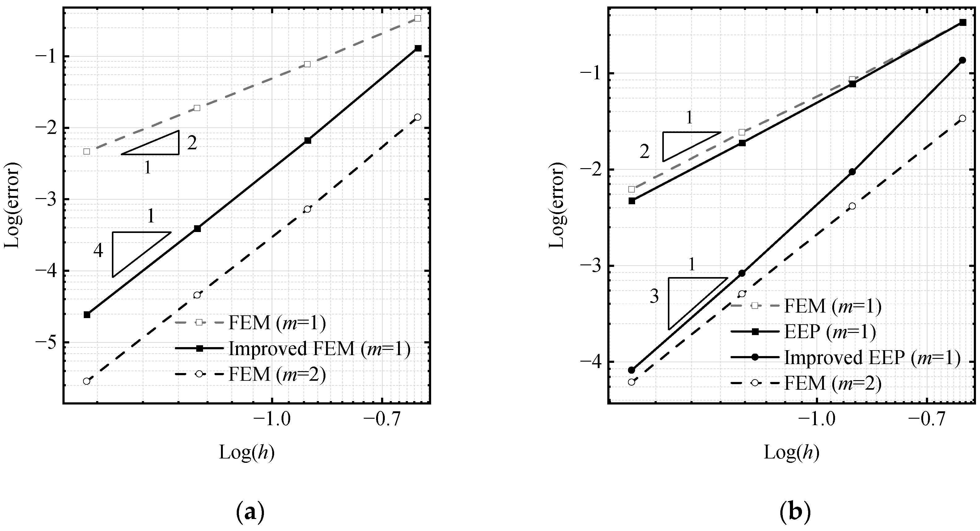
The errors of the nodal displacements, e i , max h , e ˜ i , max h , and the errors of interior displacements, e max h , e max * , e ˜ max * , are presented in Table 4, from which similar conclusions to those in Section 5.1 can be obtained. For comparison purposes, the quadratic element solutions using the same FE mesh are also shown in Figure 10, and it is noted that the improved EEP for linear elements achieves the same convergence order as that of quadratic elements.

5.4. Preliminary Application of Adaptive Algorithm to 1D Problem

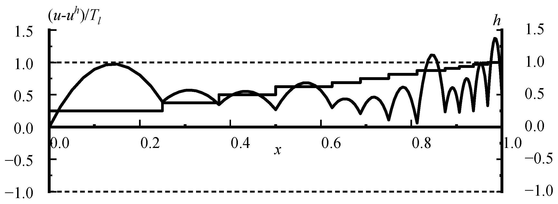
Consider the two-point boundary value problem in Section 5.1. The prescribed tolerance is set to be T l = 10 4 . Using one element as the initial mesh, the mesh π * for the first adaptivity phase is obtained by six adaptivity steps and the computed results are shown in Figure 11 and Figure 12, where the mesh π * is demonstrated by stepped line segments with each horizontal and vertical line segment representing the corresponding element size. The errors of FE solutions estimated by using the EEP solution are shown in Figure 11. Compared with real errors shown in Figure 12, the error estimate using the EEP solution cannot guarantee that the real error can meet the requirement of the error tolerance, T l , since the EEP solution is not super-convergent over the FE solution and its effective index does not converge to unity either.
Continue with the second phase of the adaptivity. The final mesh, π , as shown in Figure 13, is obtained simply by another single adaptivity step. The errors of FE solutions estimated by using the improved EEP solution are almost the same as the true error shown in Figure 14, which guarantees that Equation (18) is satisfied and hence the adaptive analysis is fully successful. In addition, for this example, N dof is only 16 from the adaptive refinement, while N dof is 64 from the uniform refinement, reflecting the remarkable efficiency gained from the adaptivity algorithm.

5.5. Stress Concentration Problem

The Poisson equation defined in Equation (1) is considered on a square domain [ 0 , 1 ] × [ 0 , 1 ] with a homogeneous Dirichlet boundary condition on all boundaries. The load term f is derived from the following given solution [29]:
u = x ( 1 x ) y ( 1 y ) arctan ( 10 2 ( x + y ) 16 )
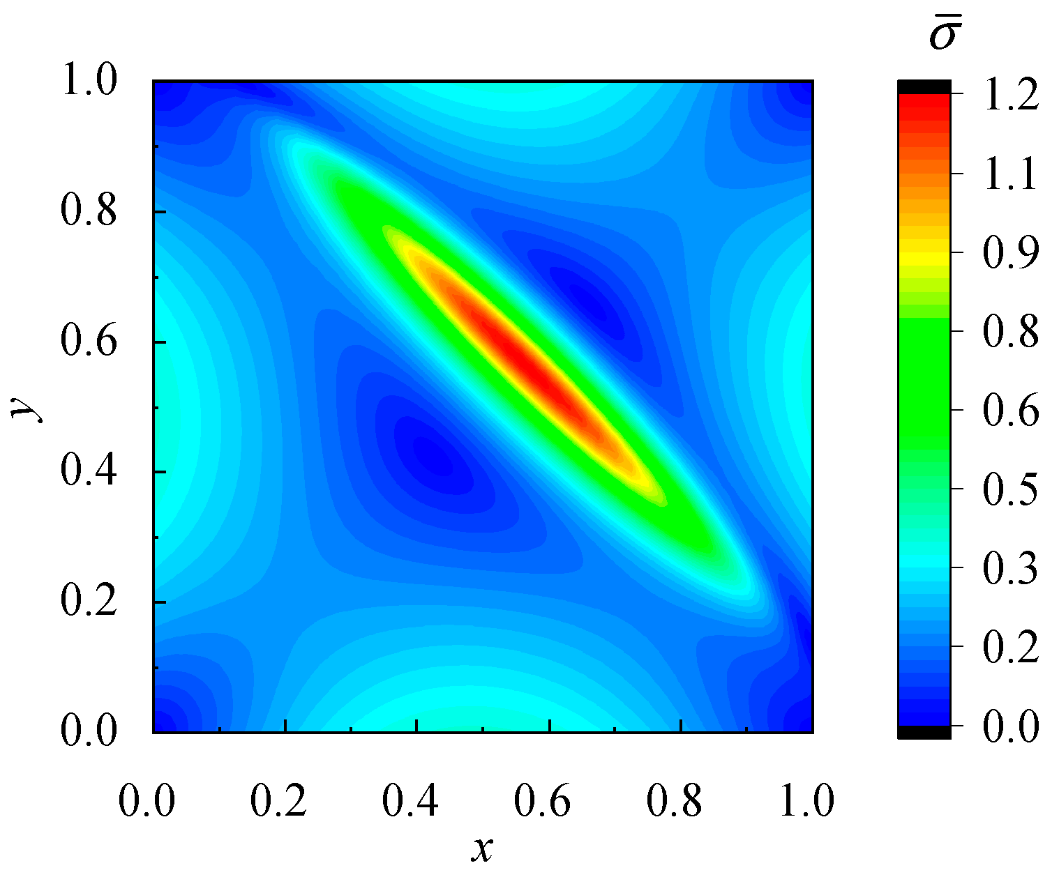
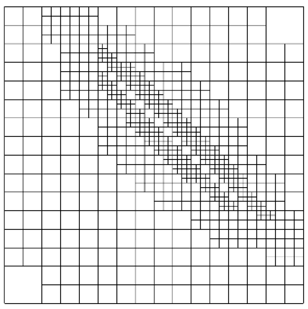
In order to reveal the difficulties of the problem, define σ ¯ = u x 2 + u y 2 as the effective gradient. The distribution of effective gradient is presented in Figure 15. It is clearly observed, from Figure 15, that the effective gradient is steeper in a diagonal narrow region, which is the tricky part of the problem. The prescribed tolerance is set to be T l = 10 3 . Using one element as the initial mesh, the first phase of adaptivity generates a mesh π * after six adaptivity steps, which is also the final mesh π after checking in the second phase, as shown in Figure 16.
Distribution of the estimated displacement error on the final mesh is presented in Figure 17a and the true error distribution is shown in Figure 17b. It is seen that ( u ˜ * u h ) / T l serves as a highly qualified point-wise error estimator with the final results strictly meeting the ultimate adaptivity criterion set in Equation (18).
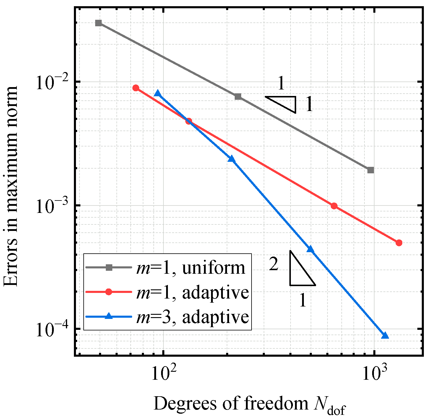
Setting T l = 10 3 , N dof is only 645 from the adaptive refinement while N dof is 1856 from the uniform refinement. Giving different T l , the convergence rates of the three refinement schemes are calculated as shown in Figure 18, where, for comparison, the adaptivity results using cubic elements computed by Dong [22] are also plotted. It is supposed that the optimal adaptive convergence rate [22,26] should be ( m + 1 ) / 2 for elements of degree m , and it is noted that all the schemes shown can achieve optimal convergence rates. However, the advantages of cubic elements are not substantial when the tolerances are not so stringent (e.g., around T l = 10 2 ). Moreover, although linear elements with the uniform refinement also achieve the optimal convergence rate 1, the adaptive refinement reduces the cost of DOFs tremendously.

5.6. Singularity Problem

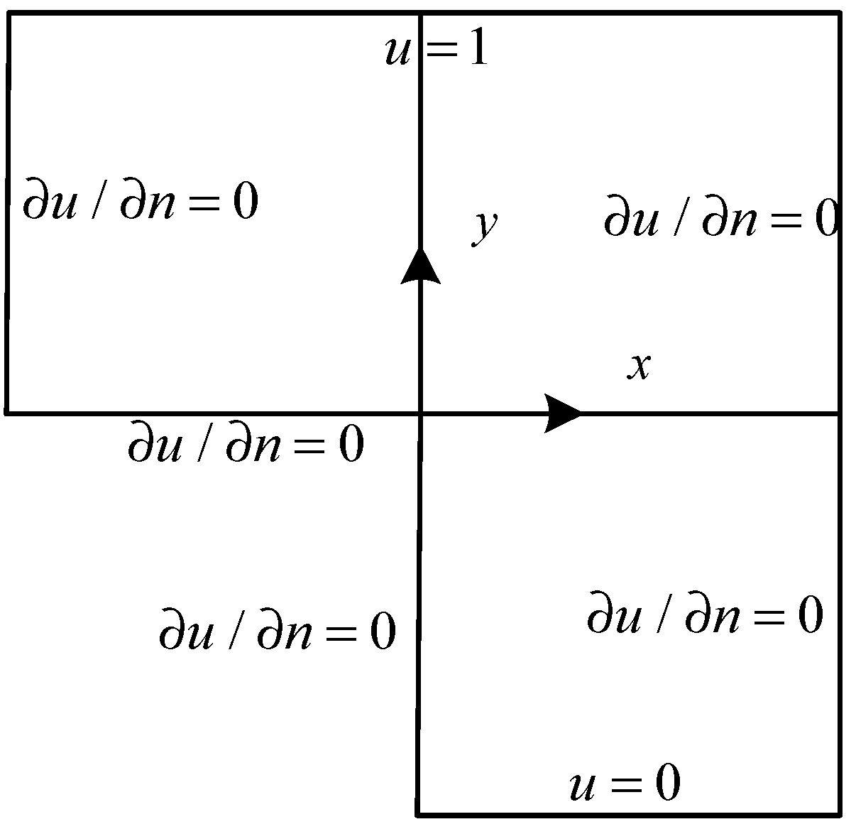
The governing equation of the problem is defined in an L-shaped domain Ω shown in Figure 19 as follows:
{ 2 u = 0 in Ω u = 0 on y = 5 , 0 x 5 u = 1 on y = 5 , 5 x 5 u / n = 0 on   the   rest   boundary
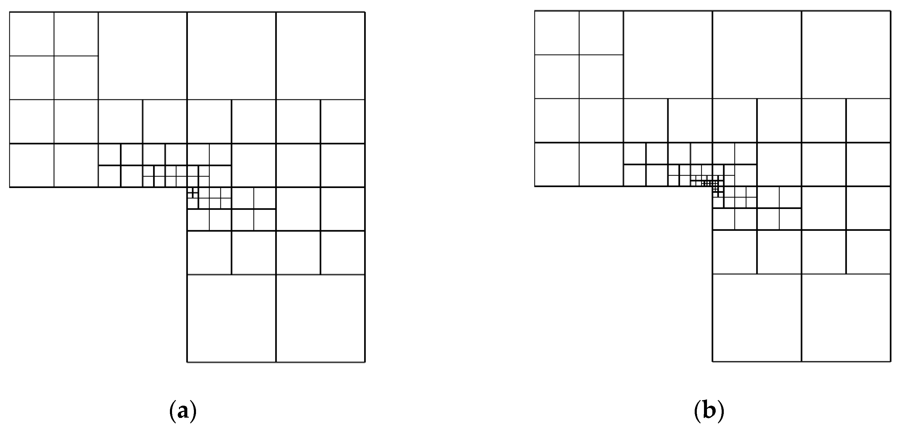
The “exact solution” was obtained on a high-density mesh, and the effective gradient is plotted in Figure 20. The fact is that u / r exhibits a singularity of ( 1 / r ) 1 / 3 at the origin [30], where r denotes the distance from the origin. Taking Figure 19 as the initial mesh of three linear elements and setting T l = 5 × 10 3 , the mesh π * from the first phase is obtained after five adaptivity steps as shown in Figure 21a. The final mesh π , as shown in Figure 21b, is obtained after three more adaptivity steps in the second phase of adaptivity.
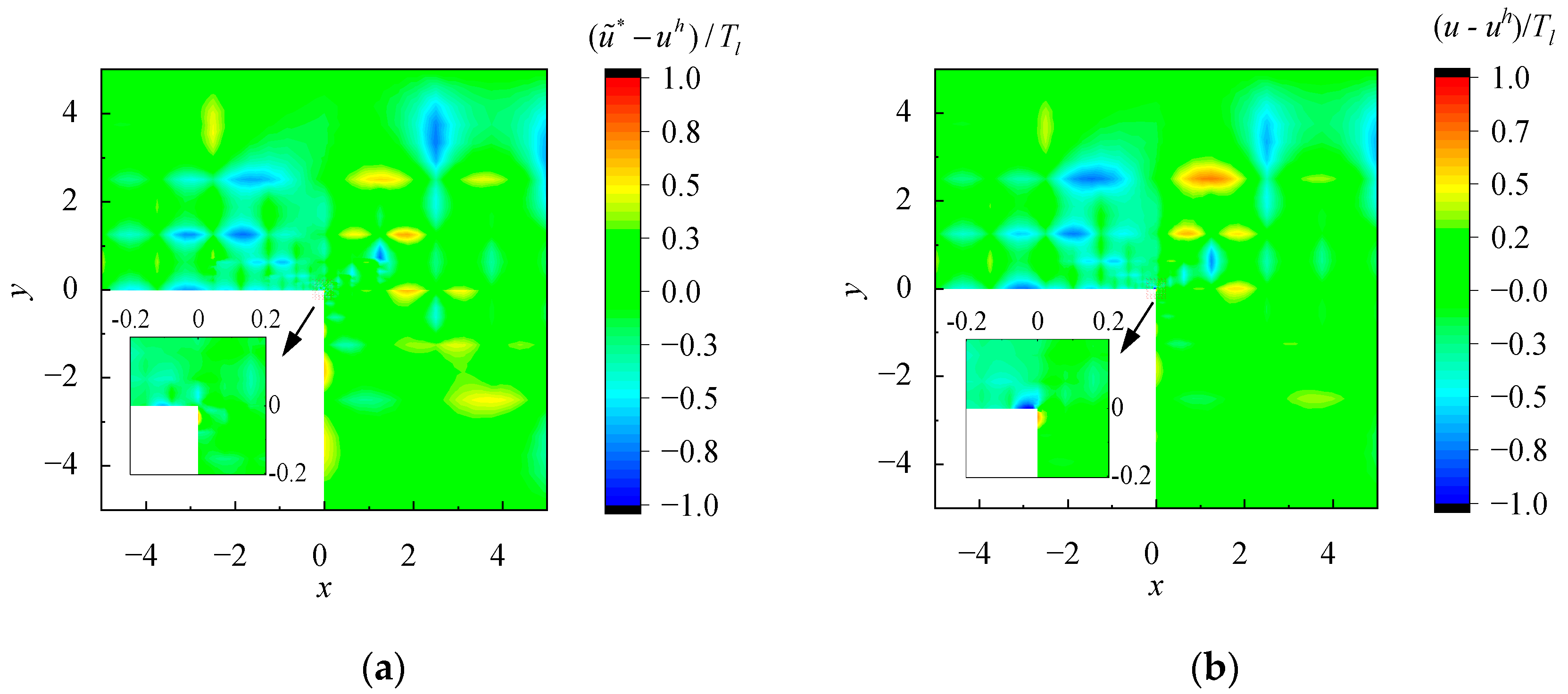
Similar to Section 5.3, the FE solution on mesh π * does not meet the ultimate adaptivity criterion set in Equation (18). It is after the follow-up checking and further refinement locally in the second phase that the FE solution on the final mesh π , generated by satisfying the stopping criterion in Equation (19), becomes fully satisfactory with Equation (18), and the contours of the distribution of the estimated and real pointwise errors on the final mesh π are presented in Figure 22.
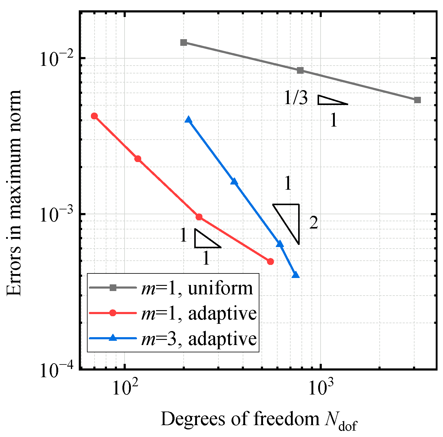
Setting T l = 5 × 10 3 , N dof is only 240 from the adaptive refinement, while N dof is 12,412 from the uniform refinement. Giving different T l , the convergence rates of the three refinement schemes are calculated as shown in Figure 23. It is noted that, for linear elements, the adaptive convergence rate tends to be the optimal ( m + 1 ) / 2 = 1 , while the uniform convergence rate is dominated by the singularity index 1 / 3 , which is very slow and inefficient. In this example, the adaptive effect of linear elements is even better than that of cubic elements even for relatively stringent tolerance, T l , which reveals the special advantage of using linear elements for singularity problems.
In short, the first three examples show that improved EEP displacements gain super-convergence compared with traditional FEM and EEP solutions. Subsequent adaptive examples show that the adaptive solution based on EEP is extended to linear elements successfully by the self-adaptive algorithm proposed in this paper with the following conclusions. Firstly, the adaptive linear FE solution satisfies the user-specified error tolerances in maximum norm on the final meshes well. Secondly, the adaptive local mesh refinement provides nearly optimal convergence rates and tremendously reduces the total cost of DOFs. Thirdly, for the stress concentration problem, the adaptivity efficiency of linear elements is not as efficient as that of cubic elements for stringent tolerances, but for relatively loose tolerances both are roughly at par. Finally, for the singularity problem, the adaptivity efficiency of linear elements even exceeds cubic elements for a wide range of the mostly used tolerances.

6. Concluding Remarks

The second-ordered nodal accuracy of linear elements in all 1D to 3D problems is the major obstacle that prevents linear elements from gaining super-convergent solutions in recovery processes, and the resulting absence of effective error estimators has in turn prevented linear elements from being used in most adaptive FE analyses. In this paper, a direct nodal accuracy improvement method for 2D and 3D linear elements is proposed, in which, without changing global stiffness matrices, simple back-substitutions for the residual nodal load vector would produce the corrective nodal displacements of the increment FE solution. On one hand, a simple addition of the increment FE solution to the conventional EEP solution provides an improved EEP solution, for which the nodal values gain fourth-order convergence and interior values gain third-order convergence in maximum norm for all multi-dimensional problems. On the other hand, this super-convergent method provides an effective and reliable error estimator for linear elements and has been successfully incorporated into a two-phased adaptivity algorithm which requires the maximum error of FE displacements to satisfy the user-specified error tolerances for 1D and 2D problems.
The adaptivity analysis for 3D problems remains to be explored, which calls for future research on a flexible, sophisticated and mature mesh generation algorithm suitable for the 3D EEP algorithm.

Author Contributions

Conceptualization, S.Y.; Methodology, Z.H., S.Y. and Q.X.; software, Z.H.; validation, Z.H.; formal analysis, S.Y. and Q.X; investigation, S.Y. and Q.X; resources, S.Y.; data curation, Z.H.; writing—original draft preparation, Z.H.; writing—review and editing, S.Y. and Q.X.; visualization, Z.H.; supervision, S.Y. and Q.X.; project administration, S.Y.; funding acquisition, S.Y. All authors have read and agreed to the published version of the manuscript.

Funding

This research was supported by the National Natural Science Foundation of China (No. 51878383, 51378293). The authors are solely responsible for the content.

Institutional Review Board Statement

Not applicable.

Informed Consent Statement

No applicable.

Data Availability Statement

No new data were created.

Conflicts of Interest

The authors declare no conflict of interest.

References

  1. Babuška, I.; Rheinboldt, W.C. A posteriori error estimates for the finite element method. Int. J. Numer. Methods Eng. 1978, 12, 1597–1615. [Google Scholar] [CrossRef]
  2. Zienkiewicz, O.C.; Taylor, R.L.; Zhu, J.Z. The Finite Element Method: Its Basis and Fundamentals, 7th ed.; Elsevier: Singapore, 2013. [Google Scholar]
  3. Babuska, I.M.; Strouboulis, T.; Upadhyay, C.S. A Model Study of The Quality of a Posteriori Error Estimators for Finite Element Solutions of Linear Elliptic Problems, With Particular Reference to the Behavior Near the Boundary. Int. J. Numer. Methods Eng. 1997, 40, 2521–2577. [Google Scholar] [CrossRef]
  4. Kelly, D.W.; Gago, D.S.R.; Zienkiewicz, O.C. A posteriori error analysis and adaptive processes in the finite element method: Part I—Error analysis. Int. J. Numer. Methods Eng. 1983, 19, 1593–1619. [Google Scholar] [CrossRef]
  5. Ladeveze, P.; Leguillon, D. Error Estimate Procedure in the Finite Element Method and Applications. SIAM J. Numer. Anal. 1983, 20, 485–509. [Google Scholar] [CrossRef]
  6. Zienkiewicz, O.C.; Zhu, J.Z. The super-convergent patch recovery and a posteriori error estimates. Part 1: The recovery technique. Int. J. Numer. Methods Eng. 1992, 33, 1331–1364. [Google Scholar] [CrossRef]
  7. Naga, A.; Zhang, Z. A posteriori error estimates based on the polynomial preserving recovery. SIAM J. Numer. Anal. 2004, 42, 1780–1800. [Google Scholar] [CrossRef] [Green Version]
  8. Boroomand, B.; Zienkiewicz, O.C. Recovery by equilibrium in patches (REP). Int. J. Numer. Methods Eng. 1997, 40, 137–164. [Google Scholar] [CrossRef]
  9. Ubertini, F. Patch recovery based on complementary energy. Int. J. Numer. Methods Eng. 2004, 59, 1501–1538. [Google Scholar] [CrossRef]
  10. Benedetti, A.; Miranda, S.D.; Ubertini, F. A posteriori error estimation based on the superconvergent Recovery by Compability in Patches. Int. J. Numer. Methods Eng. 2006, 67, 108–131. [Google Scholar] [CrossRef]
  11. Yuan, S.; Wang, M. An element-energy-projection method for post-computation of super-convergent solutions in one-dimensional FEM. Eng. Mech. 2004, 21, 1–9. (In Chinese) [Google Scholar]
  12. Payen, D.J.; Bathe, K.J. The use of nodal point forces to improve element stresses. Comput. Struct. 2011, 89, 485–495. [Google Scholar] [CrossRef]
  13. Payen, D.J.; Bathe, K.J. A stress improvement procedure. Comput. Struct. 2012, 112, 311–326. [Google Scholar] [CrossRef]
  14. Sharma, R.; Zhang, J.; Langelaar, M.; Keulen, F.V.; Aragón, A.M. An improved stress recovery technique for low order 3-D finite elements. Int. J. Numer. Methods Eng. 2018, 114, 88–103. [Google Scholar] [CrossRef] [Green Version]
  15. Babuška, I.; Rheinboldt, W.C. Adaptive approaches and reliability estimations in finite element analysis. Comput. Methods Appl. Mech. Eng. 1979, 17, 519–540. [Google Scholar] [CrossRef]
  16. Zienkiewicz, O.C.; Zhu, J.Z. A simple error estimator and adaptive procedure for practical engineering analysis. Int. J. Numer. Methods Eng. 1987, 24, 337–357. [Google Scholar] [CrossRef]
  17. Zienkiewicz, O.C.; Zhu, J.Z. The super-convergent patch recovery and a posteriori error estimates. Part 2: Error estimates and adaptivity. Int. J. Numer. Methods Eng. 1992, 33, 1365–1382. [Google Scholar] [CrossRef]
  18. Richter, T. A posteriori error estimation and anisotropy detection with dual-weighted residual method. Int. J. Numer. Methods Fluids 2010, 62, 90–118. [Google Scholar] [CrossRef]
  19. Cao, W.H. On the superconvergence patch recovery techniques for the linear finite element approximation on anisotropic meshes. J. Comput. Appl. Math. 2014, 265, 33–51. [Google Scholar] [CrossRef]
  20. Pereira, J.T.; da Silva, J. Anisotropic Mesh Refinement Considering a Recovery-Based Error Estimator and Metric Tensors. Arab. J. Sci. Eng. 2019, 44, 5613–5630. [Google Scholar] [CrossRef]
  21. Yuan, S.; Xing, Q.Y.; Ye, K.S. Self-adaptive strategy for one-dimensional finite element method based on EEP method with optimal super-convergence order. Appl. Math. Mech. (Engl. Ed.) 2008, 19, 591–602. [Google Scholar] [CrossRef]
  22. Dong, Y.Y.; Yuan, S.; Xing, Q.Y. Adaptive finite element analysis with local mesh refinement based on a posteriori error estimate of element energy projection technique. Eng. Comput. 2019, 36, 2010–2033. [Google Scholar] [CrossRef]
  23. Wiberg, N.E.; Li, X.D. Super-convergent patch recovery of finite element solution and a posteriori L2 norm error estimate. Commun. Numer. Methods Eng. 1994, 10, 313–320. [Google Scholar] [CrossRef]
  24. Douglas, J.; Dupond, T. Galerkin approximations for the two-point boundary problem using continuous, piecewise polynomial spaces. Numer. Math. 1974, 22, 99–109. [Google Scholar] [CrossRef]
  25. Chen, C.M. Structure Theory of Super-Convergence of Finite Elements; Hunan Science & Technology Press: Changsha, China, 2001. (In Chinese) [Google Scholar]
  26. Sun, H.H.; Yuan, S. Adaptive finite element analysis of free vibration of elastic membranes via element energy projection technique. Eng. Comput. 2021, 38, 3492–3516. [Google Scholar] [CrossRef]
  27. Yuan, S. The Finite Element Method of Lines; Science Press: Beijing, China; New York, NJ, USA, 1993. [Google Scholar]
  28. Yuan, S.; Xing, Q.Y.; Yuan, Q. Calculation of errors of nodal displacements in one-dimensional finite element methods using element energy projection technique. Eng. Mech. 2020, 37, 1–7. (In Chinese) [Google Scholar]
  29. Castellazzi, G.; De Miranda, S.; Ubertini, F. Adaptivity based on the recovery by compatibility in patches. Finite Elem. Anal. Des. 2010, 46, 379–390. [Google Scholar] [CrossRef]
  30. Timoshenko, S.P.; Goodier, J.N. Theory of Elasticity, 3rd ed.; McGraw-Hill: New York, NJ, USA, 1970. [Google Scholar]
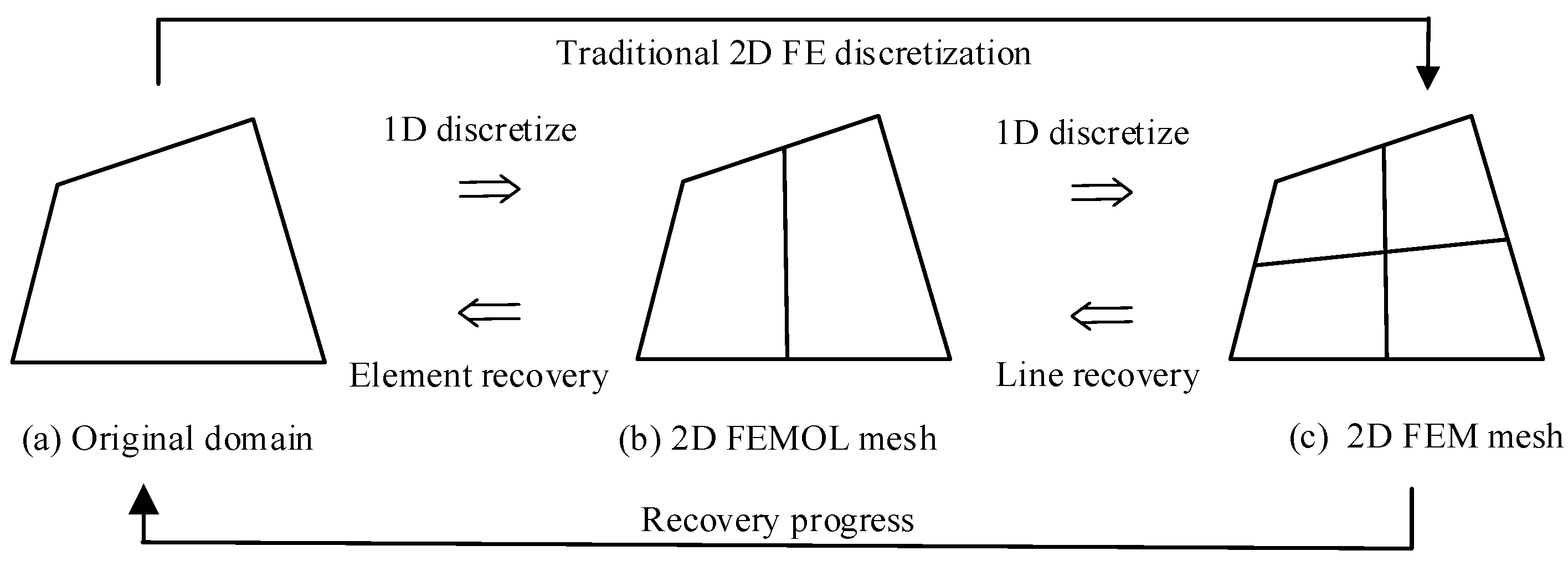
Figure 1. Global D-by-D discretization and recovery of 2D problems.
Applsci 13 02844 g001
Figure 2. Global D-by-D discretization and recovery of 3D problems.
Applsci 13 02844 g002
Figure 3. Element D-by-D recovery of 2D problems.
Applsci 13 02844 g003
Figure 4. Two approaches for nodal accuracy improvement for 2D problems.
Applsci 13 02844 g004
Figure 5. Errors of nodal displacements for the test problem.
Applsci 13 02844 g005
Figure 6. Error distributions of (a) FE solution u h ; (b) original EEP solution u * ; (c) improved FE solution u ˜ h ; (d) EEP solution u ˜ h * of u ˜ h ; (e) improved EEP solution u ˜ * .
Applsci 13 02844 g006aApplsci 13 02844 g006b
Figure 7. Error distributions.
Applsci 13 02844 g007
Figure 8. Distributions of effective index: (a) component in the x direction; (b) component in the y direction.
Applsci 13 02844 g008
Figure 9. Irregular domain.
Applsci 13 02844 g009
Figure 10. Convergence orders for: (a) nodal displacements; (b) interior displacements.
Applsci 13 02844 g010
Figure 11. Mesh π * and distribution of error ( u * u h ) / T l .
Applsci 13 02844 g011
Figure 12. Mesh π * and distribution of error ( u u h ) / T l .
Applsci 13 02844 g012
Figure 13. Final mesh π and distribution of error ( u ˜ * u h ) / T l .
Applsci 13 02844 g013
Figure 14. Final mesh π and distribution of error ( u u h ) / T l .
Applsci 13 02844 g014
Figure 15. Distribution of effective gradient.
Applsci 13 02844 g015
Figure 16. Final mesh π   ( = π * ) .
Applsci 13 02844 g016
Figure 17. Error distributions of (a) ( u ˜ * u h ) / T l and (b) ( u u h ) / T l .
Applsci 13 02844 g017
Figure 18. Convergence rates of uniform refinement and adaptive refinement.
Applsci 13 02844 g018
Figure 19. L-shaped domain and initial mesh.
Applsci 13 02844 g019
Figure 20. Distribution of effective gradient.
Applsci 13 02844 g020
Figure 21. Adaptive FE mesh: (a) mesh π * and (b) final mesh π .
Applsci 13 02844 g021
Figure 22. Error distributions of (a) ( u ˜ * u h ) / T l and (b) ( u u h ) / T l .
Applsci 13 02844 g022
Figure 23. Convergence rates of uniform refinement and adaptive refinement.
Applsci 13 02844 g023
Table 1. Convergence orders of displacements.
m N e FEMImproved FEMFEMEEPImproved EEP
e i , max h ρ e ˜ i , max h ρ e max h ρ e max * ρ e ˜ max * ρ
141.72 × 10⁻³-5.99 × 10⁻⁴-1.84 × 10⁻³-2.22 × 10⁻³-7.79 × 10⁻⁴-
84.97 × 10−41.805.44 × 10−53.467.99 × 10−41.205.38 × 10−42.041.21 × 10−42.69
161.08 × 10−42.213.31 × 10−64.042.84 × 10−41.491.14 × 10−42.231.80 × 10−52.74
322.68 × 10−52.011.88 × 10−74.148.78 × 10−51.692.75 × 10−52.062.31 × 10−62.96
Table 2. Convergence orders of displacement component in x direction.
m N e FEMImproved FEMFEMEEPImproved EEP
e i , max h ρ e ˜ i , max h ρ e max h ρ e max * ρ e ˜ max * ρ
18 × 89.68 × 10−2-1.12 × 10⁻²-2.27 × 10⁻¹-1.30 × 10⁻¹-4.65 × 10⁻²-
16 × 162.40 × 10−22.017.20 × 10−43.966.31 × 10−21.852.62 × 10−22.312.54 × 10−34.19
32 × 326.24 × 10−31.954.58 × 10−53.981.70 × 10−21.896.31 × 10−32.051.48 × 10−44.10
64 × 641.55 × 10−32.012.91 × 10−63.984.32 × 10−31.971.56 × 10−32.011.27 × 10−53.54
Table 3. Convergence orders of displacement component in y direction.
m N e FEMImproved FEMFEMEEPImproved EEP
e i , max h ρ e ˜ i , max h ρ e max h ρ e max * ρ e ˜ max * ρ
18 × 88.68 × 10−2-9.72 × 10⁻³-8.68 × 10⁻²-8.78 × 10⁻²-3.06 × 10⁻²-
16 × 162.26 × 10−21.946.56 × 10−43.892.39 × 10−21.862.26 × 10−21.963.05 × 10−33.33
32 × 325.58 × 10−32.014.84 × 10−53.766.17 × 10−31.955.58 × 10−32.013.70 × 10−43.04
64 × 641.40 × 10−32.003.32 × 10−63.871.55 × 10−31.991.40 × 10−32.004.59 × 10−53.01
Table 4. Convergence orders of displacements.
m N e FEMImproved FEMFEMEEPImproved EEP
e i , max h ρ e ˜ i , max h ρ e max h ρ e max * ρ e ˜ max * ρ
12 × 2 × 23.37 × 10−1-1.31 × 10⁻¹-3.37 × 10⁻¹-3.37 × 10−12.921.36 × 10−1-
4 × 4 × 47.71 × 10−22.136.71 × 10−34.288.53 × 10−21.987.79 × 10−22.119.44 × 10−33.84
8 × 8 × 81.88 × 10−22.043.94 × 10−44.092.42 × 10−21.821.89 × 10−22.048.29 × 10−43.51
16 × 16 × 164.66 × 10−32.012.45 × 10−54.016.19 × 10−31.974.71 × 10−32.018.19 × 10−53.34
Disclaimer/Publisher’s Note: The statements, opinions and data contained in all publications are solely those of the individual author(s) and contributor(s) and not of MDPI and/or the editor(s). MDPI and/or the editor(s) disclaim responsibility for any injury to people or property resulting from any ideas, methods, instructions or products referred to in the content.