Article

Solvent-Dispersible Nanostructured MIMI: An Experimental and Computational Study

by
Angela Candreva
1,2,*,
Giuseppe Di Maio
1,
Giovanna Palermo
2,3,
Alexa Guglielmelli
2,3,
Giuseppe Strangi
2,3,4 and
Massimo La Deda
1,2,*
1
Department of Chemistry and Chemical Technologies, University of Calabria, 87036 Rende, Italy
2
CNR-NANOTEC, Istituto di Nanotecnologia, 87036 Rende, Italy
3
Department of Physics, NLHT-Lab, University of Calabria, 87036 Rende, Italy
4
Department of Physics, Case Western Reserve University, 2076 Adelbert Rd., Cleveland, OH 44106, USA
*
Authors to whom correspondence should be addressed.
Appl. Sci. 2023, 13(5), 2982; https://doi.org/10.3390/app13052982
Submission received: 26 December 2022 / Revised: 21 February 2023 / Accepted: 23 February 2023 / Published: 25 February 2023
(This article belongs to the Special Issue New Trends in Functional and Multifunctional Advanced Materials)

Abstract

:
A MIMI (metal–insulator-metal–insulator) nanoparticle was conceived and synthesized. It consists of a core of gold nanoparticles of different shapes, covered by a silica shell in turn covered by a layer of gold and finally by another silica shell. This hybrid nano-matryoshka, completely dispersed in water, was characterized by UV–Vis and TEM spectroscopy, comparing the architecture and photophysical properties of each synthetic step. Through a numerical simulation, it was possible to study in depth the absorption and extinction cross sections, determining the role of the various layers. This is an example of architecture used in the construction of metamaterials, the first in the form of a water-dispersed nanoparticles.

1. Introduction

Nanofabrication technologies [1,2,3] have attracted researchers to explore the field of plasmonic modes [4,5,6,7], such as localized surface plasmons (LSPs) [8,9] and coupled plasmonic systems [10,11,12], which strongly increase an interacting electromagnetic field [13,14]. These features are generally shown by suitably coupling a metal with a dielectric, while, more recently, metal–insulator–metal–insulator structures (MIMI) have provided encouraging results. MIMI is a new architecture in which an insulator is enclosed by two metal claddings, highlighting potential attractive features [15,16,17,18,19] which depend on the thickness and composition of the surfaces that compose it [20,21,22]. On the MIMI structures are based metamaterials, that constitute the last frontier in the search for new materials, possessing properties not found in nature [23,24,25].
A further step forward is represented by three-dimensional MIMI systems composed of nanoparticle films that can achieve major advances compared to multilayered planar devices; their electronic and optical properties are encouraging for numerous applications such as third-generation solar cells, light-emitting diodes, field-effect transistors [26,27,28,29]. Ultimately, the performance of these devices is based on the modulation of the energy levels and optical properties of the nanoparticles by regulating their shape, size, surface and chemical composition [30,31,32,33,34].
With respect to the available MIMI devices, which consist of a solid array [18,35], the aim of this work was to obtain a MIMI nanoparticle in colloidal dispersion. Among the many advantages of having a potential metamaterial in colloidal dispersion, there is their in vivo use for the detection of particular analytes present in biological fluids, while the current detection systems based on metamaterials require the collection of these fluids [36]. Recent advances in nanofabrication have encouraged the development of new plasmonic biosensors that can go beyond the limits of conventional plasmonic sensors [37,38,39]. A. V. Kabashin et al. demonstrated an improvement in biosensing technology using a plasmonic metamaterial based on a porous nanorods layer [40]. Furthermore, the possibility of having nanosized metamaterials allows the functionalization of these nanoplatforms, favoring extreme versatility.
To obtain solvent-dispersible nanoparticle MIMI, a synthetic protocol based on a seed-mediated growth approach [41,42,43,44,45] is presented, to obtain a nano-matryoshka array by the alternation of gold and silica layers.
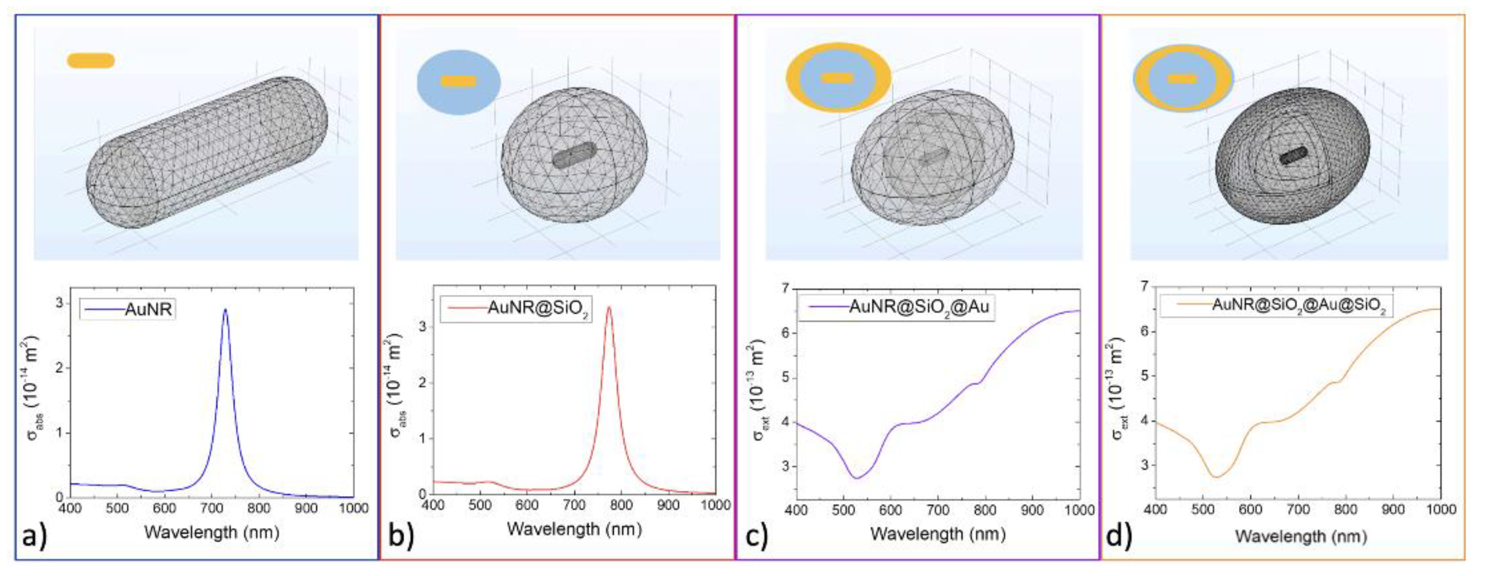
A numerical simulation based on a Finite Element Method (FEM) analysis was conducted on each member of the rod–core MIMI family (samples a, b, c, d) to evaluate the absorption and extinction cross section of a single nano-object, displaying a good agreement with the experimental results.

2. Materials and Methods

All chemicals were purchased from Sigma Aldrich (highest purity grade available) and used as received.

2.1. Chemicals

CTAB (hexadecyltrimethylammonium bromide, ≥96%), 5-bromosalicylic acid (5-BrSA, technical grade, 90%), tetrachloroauric acid trihydrate (HAuCl4•H2O, ≥99.9%), AgNO3, (≥99.0%), L-ascorbic acid (AA, ≥99%), sodium citrate (99%), sodium borohydride (NaBH4, 99%) were used as received. Milli-Q water (resistivity 18.2 MΩ•cm at 25 °C) was used in all experiments. All glassware was washed with aqua regia, rinsed with water, sonicated three times for 3 min in Milli-Q water, and dried before use. TEOS (tetraethyl orthosilicate, 99.9%), NaOH (98%), APTES (3-Aminopropyl triethoxysilane), NH4OH (34%) and MeOH were used for the SiO2 overcoating.

2.2. Instruments

The extinction spectra were acquired with a Perkin Elmer Lambda 900 spectrophotometer. The size and morphology of the gold nanoparticles were investigated by a Jeol JEM-1400 Plus 120 kV transmission electron microscope (TEM). The samples for TEM were prepared by depositing a drop of a diluted colloidal dispersion on 300-mesh copper grids. After evaporation of the solvent in air at room temperature, the particles were observed at an operating voltage of 80 kV. The core dimension and the thickness of the shell were measured graphically on the TEM images, using the ImageJ program. For each sample, 100 nanoparticles were considered, and for this data population, the standard deviation was obtained.

2.3. Synthetic Procedure

The synthetic strategy involved the preparation of CTAB-coated gold nanorods [46,47] (AuNR), which were subsequently coated with a silica shell (AuNR@SiO2). By suitably functionalizing the silica surface [48,49], the gold nanorods (AuNR@SiO2) were decorated with gold seeds, indicated below as AuNS@NaCit, (AuNR@SiO2@seed), which then gave rise to a homogeneous gold shell (AuNR@SiO2@Au). Finally, these nanorods were covered with an additional silica shell (AuNR@SiO2@Au@SiO2), providing the MIMI structure.
To study both the versatility of the synthetic protocol and the effect on the plasmonic properties of the nano-matryoshka, the starting nanoparticles which formed the core of the nano-matryoshka, were produced in a mix of shapes, AuNP@CTAB, and constituted the starting nanoparticles for a similar family of MIMI systems which led to the final production of a nano-matryoshka with a mixed-shape core, AuNP@SiO2@Au@SiO2. Each member of this family was isolated, characterized and compared with the members of the analogous family having a rod-shaped core, as previously illustrated.
Chart 1 reports the synthetic steps followed in the preparation of the two MIMI systems, i.e., AuNR@SiO2@Au@SiO2 and AuNP@SiO2@Au@SiO2.

2.4. AuNR

Preparation of the seed solution. We added 25 μL of a 5.0x-2 M metal salt tetrachloroauric acid, HAuCl4, water solution to 4.7 mL of a 0.1 M CTAB water solution. At this point, 300 μL of a freshly prepared 1.0x-2 M sodium borohydride, NaBH4, aqueous solution was injected under vigorous stirring. The metal reduction was complete (from Au(III) to Au(0)). The color of the solution became brown. The seed solution was left undisturbed for 30 min, before use, to ensure that the excess sodium borohydride was consumed [46,50,51].
Preparation of the growth solution. We injected 45 mg of 5-BrSA into 50 mL of a 0.05x-2 M CTAB aqueous solution. Only after complete solubilization was ascertained, 480 μL of a 1.0x-2 M AgNO3 water solution was added. The sample remained under slow stirring for 15 min at a temperature of 25 °C, and then 500 μL of a 5.0x-2 M HAuCl4 aqueous solution was added to the mixture, starting the pre-reduction step. At the selected pre-reduction time, 130 μL of a 0.1 M AA aqueous solution was added under vigorous stirring, followed by 80 μL of the seed colloidal dispersion. After a few seconds, the stirring was turned off, and after 4 h, the sample was centrifuged (9000 rpm, 20 min, 30 °C). A clear aqueous colloidal dispersion was obtained.
In this step (growth), elongated micelles of CTAB formed that acted as templating agents for the successive AuNR growth. Here, no nucleation process took place. The compound 5-BrSa, introduced as an aromatic additive to a CTAB water solution, intercalated within the CTAB bilayer, improving the stiffness and symmetry of the growing particles. Silver nitrate was added to promote the anisotropic rod-like shape [46,52].

2.5. AuNP@CTAB

The synthetic protocol was the same reported for AuNR@CTAB, with the exception of CTAB and AgNO3 concentrations in the growth solution, which were reduced by 10 times [52].

2.6. AuNP@SiO2, AuNR@SiO2

According to the protocol reported in a previous paper [48], an aqueous solution of CTAB was added to 2 mL of an aqueous dispersion of gold nanoparticles (0.3x-3 M), reaching the final concentration of 1.0x-3 M. After a few seconds, a 0.1 M NaOH aqueous solution was added under vigorous stirring, reaching a pH value of 8.5, followed by three additions (under gentle stirring, at room temperature) of 12 μL each of TEOS 20% v/v in methanol, at 1 h intervals from each other. After 14 h, the mixture was centrifuged in MilliQ water twice at 6000 rpm for 10 min, and the sample was dispersed in 4 mL of EtOH. At this point, 0.5 mL of distilled water and 0.5 mL of NH4OH were added to the nanoparticle dispersion, followed, 30 min later, by 3.75 µL of TEOS and 3.75 µL of APTES. After 12 h, 3 cycles of centrifuge were carried out, and a pellet was obtained. A part of this pellet was dissolved in water, obtaining a clear colloidal dispersion.

2.7. AuNS@NaCit

Sodium citrate (3 mg) was added to 40 mL of distilled water under stirring and at a controlled temperature (30 °C). Then, a HAuCl4 water solution (0.020 mL, 0.05 M) was added and, after a few minutes, 1.6 mL of a freshly prepared 1.0 x-2 M NaBH4 water solution was injected under vigorous stirring. Instantaneously, the solution became, red confirming the formation of small gold nanospheres, AuNS@NaCit [52] (Figure S1 in ESI, TEM images and UV–Vis spectra).

2.8. AuNP@SiO2@seed, AuNR@SiO2@seed

An aqueous dispersion of AuNS@NaCit (4 mL, 1.0x-4 M) was added to the pellet of silica shell/gold core nanoparticles (AuNP@SiO2, AuNR@SiO2) under sonication. After a few minutes, a cloud of nanoparticles precipitated at the bottom of the vial, leaving the solution colorless. The supernatant was removed, and the precipitate was dispersed in distilled water, obtaining a clear colloidal dispersion.

2.9. K-Gold Solution

A water solution of K2CO3 (14 mg in 50 mL) was prepared and added to 750 mL of HAuCl4 (25 mM). The mixture was aged in the dark, overnight [53].

2.10. AuNP@SiO2@Au, AuNR@SiO2@Au

We added 200 µL of AuNP@SiO2@seed or AuNR@SiO2@seed nanoparticles samples to 3 mL of the K-Gold solution. Then, 40 µL of 37 wt% formaldehyde in water was added, and the mixture was rapidly shaken until the solution became grey-purple. After 30 min, the solution was purified by one cycle of centrifugation at 9000 rpm for 15 min, and a clear water solution was obtained.

2.11. AuNP@SiO2@Au@SiO2, AuNR@SiO2@Au@SiO2

We added 30 µL of APTES 20% v/v in methanol, drop by drop. to the AuNP@SiO2@Au or AuNR@SiO2@Au nanoparticles colloidal dispersions, in alkaline conditions, under mild stirring for 3 h. Then, a centrifugation at 9000 rpm for 15 min was performed, obtaining a clear water solution.
The concentrations of the nanoparticles were calculated according to Scarabelli et al. [47], considering that all Au3+ was reduced to Au0.

2.12. Theoretical Calculations

Simulations regarding the optical characteristics of the nanorods-derived nano-matryoshka were conducted using the commercially available finite element analysis software COMSOL Multiphysics (COMSOL, Inc., Burlington, MA, USA) version 5.4, module ‘Electromagnetic Waves, Frequency Domain’ (EWFD) [54,55,56,57,58]. With this module, it is possible to study electromagnetic wave propagation, resonance effects at the nanoscale, electromagnetic field distributions through a scattered field formulation. The finite element method operates by discretizing the modeling domains into smaller, simpler domains, named elements. The solution is computed by assembling and solving a set of equations over all the elements of the model. The 3D simulation domain contained the nanoparticle immersed in the surrounding medium, which was in turn surrounded by a Perfectly Matched Layer (PML) to mimic an open and nonreflecting infinite domain. The amplitude of the plane wave | E 0 | was calculated for the incoming illumination intensity I 0 according to I 0 = n c ε 0 | E 0 | 2 / 2 , where n is the refractive index of the surrounding medium, c is the speed of light, and ε 0 is the vacuum permittivity. Maxwell’s equations, intended for the scattering of electromagnetic radiation with nanoparticles, were solved in the model [59]. In particular, the wavelength-dependent optical characteristics, including the absorption cross section and the scattering cross section, were calculated. Parametric Sweep was introduced from 400 nm to 1000 nm, with a step size of 5 nm. The simulation computed the local electromagnetic field on each mesh point, accompanied by an incident plane wave propagating in the z-direction by the electric field polarized along the x-axis and y-axis to opportunely excite the transversal and longitudinal resonance of the gold nanorods. The nanoparticle was modeled in all its constituent parts, starting from (i) AuNR@CTAB, (ii) AuNR@SiO2, (iii) AuNR@SiO2@Au and (iv) AuNR@SiO2@Au@SiO2. An “extra-fine” mesh, consisting of a free triangular and tetrahedral geometry with about 25,000–80,000 elements (from the AuNR@CTAB to the AuNR@SiO2@Au@SiO2 structure) was considered. For the outer boundary of the spherical domain, the scattering boundary condition was used to make the boundary transparent for the scattered wave. All the parameters used in the numerical modelling are listed in Table S1. The absorption cross section and the scattering cross section were derived by the calculation of the rate of the electromagnetic energy that was absorbed ( W abs ) and scattered ( W sca ) by the nanoparticle with respect to the incident irradiance, defined as the energy flux of the incident wave ( P inc ): σ abs = W abs / P inc and σ sca = W sca / P inc , respectively. The total absorbed energy was derived by integrating the energy loss ( Q loss ) over the volume of the particle ( W a b s = V P Q l o s s d V ), while the scattered energy was derived by integrating the Poynting vector ( P sca ) over an imaginary sphere around the particle ( W s c a = S P s c a   · n   d S ). The extinction cross section ( σ e x t ) represents the amount of energy removed from the incident field due to absorption and scattering ( σ e x t = σ a b s + σ s c a ).

3. Results and Discussion

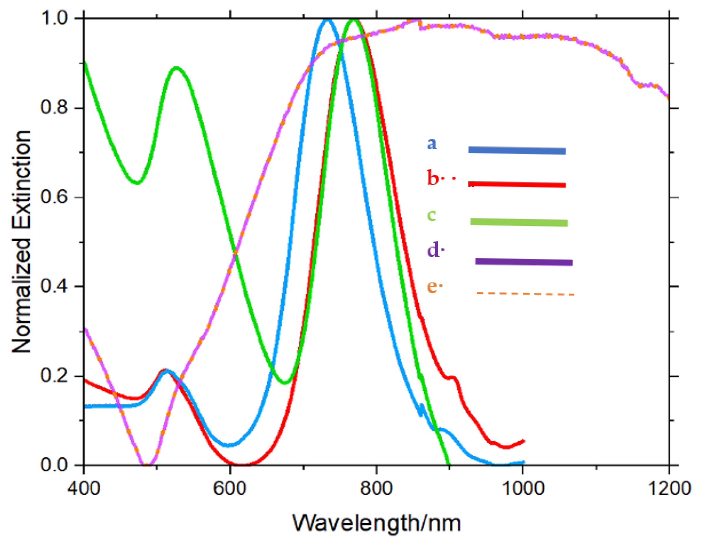
All the samples were morphologically characterized by TEM and, from a spectroscopic point of view, by collecting the extinction spectra of the aqueous colloidal dispersion. For samples with a core consisting of gold nanorods, the theoretical spectra were calculated. Following Chart 1, we first discuss all nanoparticles having a gold rod-shaped core. Figure 1a reports the TEM images of AuNR@CTAB, showing the gold nanorods coated with CTAB (57 × 18 nm), while Figure 2 (blue line) displays the experimental extinction spectrum of its water dispersion.
A longitudinal band at 732 nm and a transversal one at 515 nm were observed. According to the FWHM of the longitudinal band and TEM image, the sample was homogeneous in shape and size. By modeling CTAB-covered gold nanorods of 57 × 18 nm (Figure 3a), the calculated spectrum fit satisfactorily with the experimental one. In Figure 1b, the TEM image of the AuNR@SiO2 sample is reported: a thick silica shell of 60 nm formed around the gold core. When the gold nanorods were covered by the silica shell, their longitudinal band red-shifted to 770 nm (Figure 2, red line). The simulated absorption and extinction cross sections for AuNRs in the same conditions as the experimental measurements (Figure 3a,b) showed a good agreement with the experimental results. In particular, with the addition of the silica shell, the two plasmonic peaks red-shifted, appearing at 520 nm and 775 nm, respectively, due to a change in the refractive index of the surrounding medium (from water to silica) around the gold nanorods. The metal–dielectric interface in the case of nanoparticles covered with CTAB consisted of water (nd20 = 1.33, water refractive index) embedding CTAB. In the case of nanoparticles covered with the silica shell, the dielectric had a higher refractive index (nd20 = 1.45, silica refractive index) [60,61,62]. The TEM image of AuNR@SiO2@seed (Figure 1c) shows the whole silica surface functionalized with the small gold seeds. After the seed solution addition, the transversal band increased, due to the contribution of the seeds (Figure 2, green line), while the position of the transversal and longitudinal bands remained unvaried with respect to that observed for the previous sample. In the AuNR@SiO2@Au sample, the gold seeds gave way to a gold shell with a thickness of about 55 × 28 nm, giving rise to MIMI nanoparticles with overall dimensions of about 280 × 200 nm (Figure 1d). The spectral behavior (Figure 2, violet line), confirmed by calculations (Figure 3c) dramatically changed with respect to the previous samples: scattering appeared to be predominant over absorption, and a broadened band in the range from 730 nm to 1200 nm was recorded. The transversal band appeared barely visible.
Finally, the previous MIMI nanoparticle was covered by a 3 nm thick silica shell, giving rise to the MIMI nano-matryoshka AuNR@SiO2@Au@SiO2, reported in the TEM image of Figure 1e. The outermost shell of silica of a few nm did not make any contribution to the optical response of the nanoparticle, as shown by the spectrum in Figure 2 (orange dotted line) and confirmed by calculation (Figure 3d). EDX measurements were conducted on AuNR@SiO2@Au@SiO2 (Figure S3 in ESI)
The comparison between the experimental and the calculated extinction spectra allowed evaluating the contribution of scattering and absorption (see Figure S2 in ESI). In the case of AuNR and AuNR@SiO2, it was evident that the scattering contribution was negligible compared to the absorption one, while in the case of AuNR@SiO2@Au and AuNR@SiO2@Au@SiO2, the scattering contribution was preponderant over that of absorption. This was attributable to the larger size of the last two samples compared to the first two.
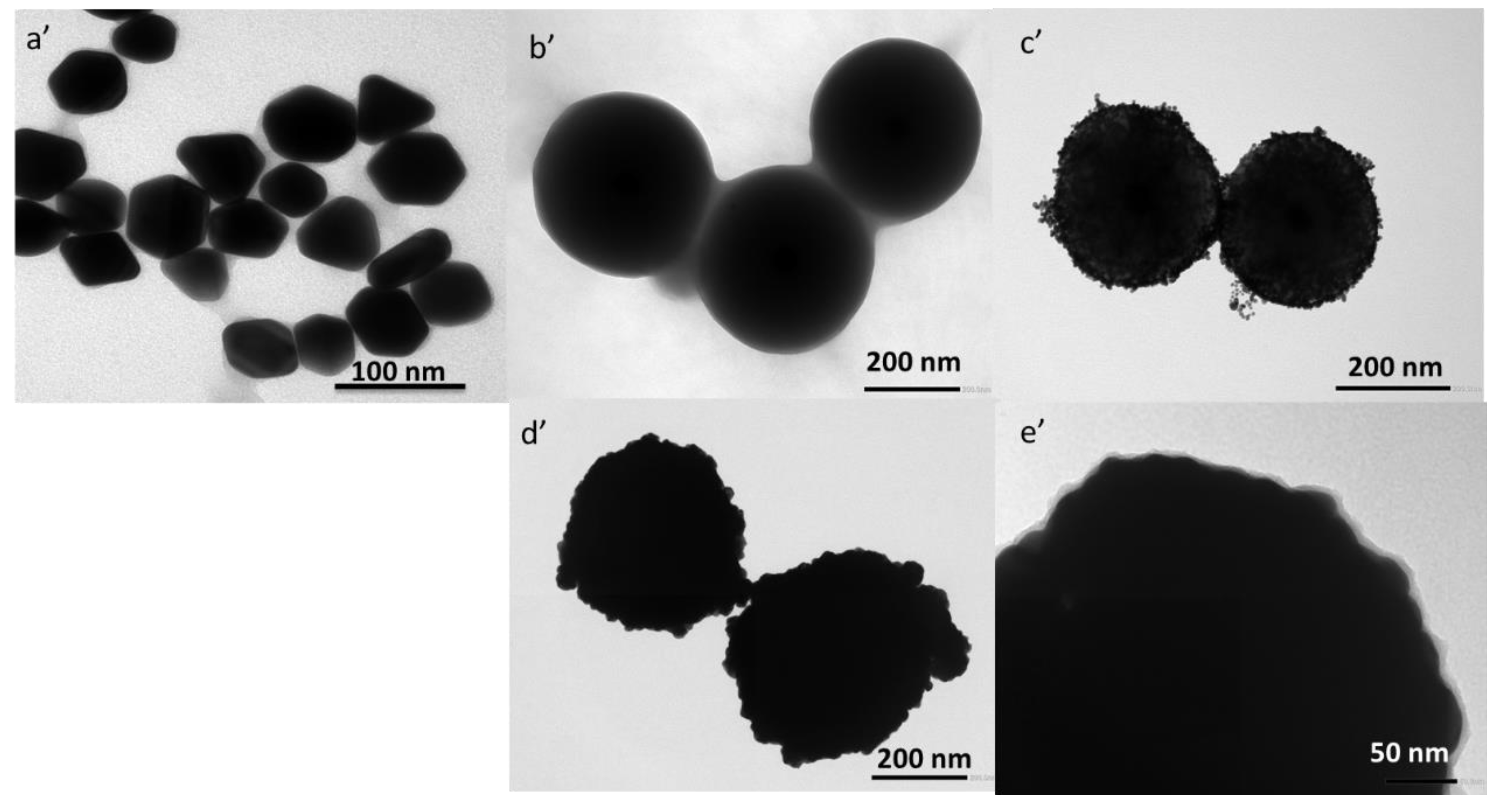
As described in the previous paragraph, the same synthetic procedure applied to rod-shaped nanoparticles (i.e., AuNR@CTAB) was applied to a mix of gold nanoparticles with different shapes (i.e., AuNP@CTAB), in order to test its applicability and to study the influence of the starting material on the final product (i.e., AuNP@SiO2@Au@SiO2). Figure 4 shows the TEM image of the family system reported in Path 2 of Chart 1. Comparing these images with those shown in Figure 1, the most relevant difference obviously concerns the shape of the starting AuNPs, while the other samples evidence the same architecture of the family system of Path 1 (see Chart 1), confirming the versatility of the proposed synthetic protocol.
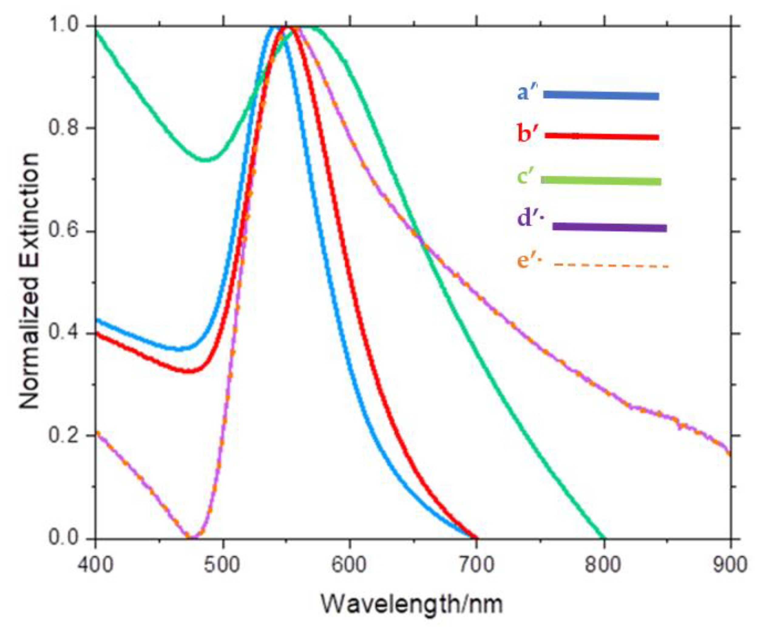
Making a comparison between AuNR and the AuNP family, it is clear that the plasmonic properties of the nano-matryoshka changed according to the metal core. The plasmonic peaks moved to different wavelengths as the shape of the nanoparticle changed. In fact, in both proposed cases, AuNR and AuNP (Figure 2 and Figure 5, experimental spectra), the plasmonic bands changed as the matryoshka took shape. As shown in Figure 5, AuNP showed only one plasmonic band. The peaks of AuNP@SiO2@Au and AuNP@SiO2@Au@SiO2, violet line and dotted orange line, respectively, were quite similar because the contribution of the thin silica shell in AuNP@SiO2@Au@SiO2 was negligible. On the other hand, the two peaks of AuNR, red shifted as the matryoshka took shape (Figure 2). The broadening of the longitudinal band was impressive in the last two steps, AuNR@SiO2@Au and AuNR@SiO2@Au@SiO2 (violet line and orange dotted line in Figure 2), due to the large dimensions of the nano-matryoshka. Also in this case, there was an overlap between the two bands, because the contribution of the thin silica shell was negligible.

4. Conclusions

This paper presents the first example of a nanomaterial with MIMI architecture dispersed in an aqueous environment. The nanomaterial was designed and synthesized according to a seed-mediated growth approach which, starting from CTAB-coated gold nanorods, gave shape, step by step, to a hybrid hierarchical structure consisting of the alternation of gold and silica shells, recalling the structure of a matryoshka. The same protocol was applied to any shape of the nanoparticles, and the final plasmonic properties of the nano-matryoshka depended on the shape of the metal core.
All the intermediates were characterized, both from a morphological point of view, by TEM, and optically, by UV–Vis spectroscopy. When the matryoshka took shape, the spectrum of both samples changed drastically: the longitudinal band of the nanorods widened substantially until reaching wavelengths in the NIR range, the band of the AuNP@CTAB-derived nanosystems continued to fall into the visible range, but a shoulder around 700 nm was impressive. The computational results, based on an FEM analysis, confirmed the experimental ones, highlighting that the final plasmonic properties of the nano-matryoshka depended on the shape of the metal core and on the refractive index of the surrounding media and could be suitably tuned to the NIR spectrum region. Furthermore, the comparison between the experimental and the calculated spectra allowed estimating the mutual contribution of scattering and absorption to the optical properties of the nanosystems. The computational effort represents a practical tool for the development of matryoshka with specific plasmonic features.
These findings could have application in various fields; in particular, the construction of metamaterials in aqueous solution is an exceptional goal, considering the possibility to properly functionalize the nanoparticle surface, obtaining a biocompatible nano-matryoshka that, by exploiting the sensitivity of a metamaterial, could be used for in vivo biopsies.

Supplementary Materials

The following supporting information can be downloaded at: https://www.mdpi.com/article/10.3390/app13052982/s1, Figure S1: TEM images and Uv–Vis spectra of AuNS@NaCit; Cross section calculations; Figure S2: Calculated extinction, absorption and scattering cross sections of (a) AuNR, (b) AuNR@SiO2, (c) AuNR@SiO2@Au and (d) AuNR@SiO2@Au@SiO2; Figure S3: EDX measurement of AuNR@SiO2@Au@SiO2; Table S1: Parameters used in the numerical modelling of the nanostructures.

Author Contributions

A.C. synthesized and characterized the samples, wrote the draft of the manuscript, prepared the figures; G.D.M. reviewed the manuscript; G.P., A.G. and G.S., conducted the theoretical study; M.L.D. supervised all steps, wrote the main manuscript text, reviewed and validated the manuscript. All authors have read and agreed to the published version of the manuscript.

Funding

This research received no external funding.

Institutional Review Board Statement

Not applicable.

Informed Consent Statement

Not applicable.

Data Availability Statement

We encourage all authors of articles published in MDPI journals to share their research data. In this section, please provide details regarding where data supporting reported results can be found, including links to publicly archived datasets analyzed or generated during the study. Where no new data were created, or where data is unavailable due to privacy or ethical restrictions, a statement is still required. Suggested Data Availability Statements are available in section “MDPI Research Data Policies” at https://www.mdpi.com/ethics.

Acknowledgments

The authors are grateful to NLHT, Nanoscience Laboratory for Human Technologies, POR Calabria FESR-FSE 14/20, and to “Progetto STAR 2—PIR01_00008”—Ministero dell’Università e Ricerca/Italian Ministry of University and Research.

Conflicts of Interest

The authors declare no conflict of interest.

References

  1. Roco, M.C. Nanotechnology: Convergence with modern biology and medicine. Curr. Opin. Biotechnol. 2003, 14, 337–346. [Google Scholar] [CrossRef] [PubMed] [Green Version]
  2. Roco, M.C. Principles of convergence in nature and society and their application: From nanoscale, digits, and logic steps to global progress. J. Nanoparticle Res. 2020, 22, 321. [Google Scholar] [CrossRef] [PubMed]
  3. Candreva, A.; De Rose, R.; Perrotta, I.D.; Guglielmelli, A.; La Deda, M. Light-Induced Clusterization of Gold Nanoparticles: A New Photo-Triggered Antibacterial against E. coli Proliferation. Nanomaterials 2023, 13, 746. [Google Scholar] [CrossRef]
  4. Fu, Y.; Fang, F.; Xu, Z. Nanofabrication and Characterization of Plasmonic Structures. Nanofabrication 2011, 4, 243–266. [Google Scholar] [CrossRef] [Green Version]
  5. Henzie, J.; Lee, J.; Lee, M.H.; Hasan, W.; Odom, T.W. Nanofabrication of plasmonic structures. Annu. Rev. Phys. Chem. 2009, 60, 147–165. [Google Scholar] [CrossRef] [Green Version]
  6. Rane, A.V.; Kanny, K.; Abitha, V.K.; Thomas, S. Methods for Synthesis of Nanoparticles and Fabrication of Nanocomposites; Elsevier Ltd.: Amsterdam, The Netherlands, 2018. [Google Scholar]
  7. Mohan Bhagyaraj, S.; Oluwafemi, O.S. Nanotechnology: The Science of the Invisible; Elsevier Ltd.: Amsterdam, The Netherlands, 2018. [Google Scholar]
  8. Amendola, V.; Pilot, R.; Frasconi, M.; Maragò, O.M.; Iatì, M.A. Surface plasmon resonance in gold nanoparticles: A review. J. Phys. Condens. Matter 2017, 29, 1–48. [Google Scholar] [CrossRef] [PubMed]
  9. Tang, Y.; Zeng, X.; Liang, J. Surface plasmon resonance: An introduction to a surface spectroscopy technique. J. Chem. Educ. 2010, 87, 742–746. [Google Scholar] [CrossRef] [PubMed] [Green Version]
  10. Chen, J.; Gong, M.; Fan, Y.; Feng, J.; Han, L.; Xin, H.L.; Cao, M.; Zhang, Q.; Zhang, D.; Lei, D.; et al. Collective Plasmon Coupling in Gold Nanoparticle Clusters for Highly Efficient Photothermal Therapy. ACS Nano 2022, 16, 910–920. [Google Scholar] [CrossRef] [PubMed]
  11. Scheeler, S.P.; Mühlig, S.; Rockstuhl, C.; Hasan, S.B.; Ullrich, S.; Neubrech, F.; Kudera, S.; Pacholski, C. Plasmon coupling in self-assembled gold nanoparticle-based honeycomb islands. J. Phys. Chem. C 2013, 117, 18634–18641. [Google Scholar] [CrossRef]
  12. M.C. Daniel, D.A. Plasmon coupling in self-assembled gold nanoparticle-based honeycomb islands. Chem. Rev. 2004, 104, 293–346. [Google Scholar]
  13. Hanske, C.; Tebbe, M.; Kuttner, C.; Bieber, V.; Tsukruk, V.V.; Chanana, M.; König, T.A.F.; Fery, A. Strongly coupled plasmonic modes on macroscopic areas via template-assisted colloidal self-assembly. Nano Lett. 2014, 14, 6863–6871. [Google Scholar] [CrossRef] [Green Version]
  14. Ritchie, R.H. Surface plasmons in solids. Surf. Sci. 1973, 34, 1–19. [Google Scholar] [CrossRef]
  15. Kazanskiy, N.L.; Khonina, S.N.; Butt, M.A. Plasmonic sensors based on Metal-insulator-metal waveguides for refractive index sensing applications: A brief review. Phys. E Low-Dimensional Syst. Nanostructures 2020, 117, 113798. [Google Scholar] [CrossRef]
  16. Ghasemi, M.R.; Bayati, M.S. Proposal for metal–insulator–metal plasmonic power splitter and demultiplexer suitable for implementation in optical switches. IET Optoelectron. 2021, 15, 200–206. [Google Scholar] [CrossRef]
  17. Liang, Z.; Wen, Y.; Zhang, Z.; Liang, Z.; Xu, Z.; Lin, Y.S. Plasmonic metamaterial using metal-insulator-metal nanogratings for high-sensitive refraction index sensor. Results Phys. 2019, 15, 102602. [Google Scholar] [CrossRef]
  18. Tamura, M.; Kagata, H. Analysis of metal-insulator-metal structure and its application to sensor. IEEE Trans. Microw. Theory Tech. 2010, 58, 3954–3960. [Google Scholar] [CrossRef]
  19. Shin, Y.J.; Son, J.H.; Lee, D.H.; Lee, M.H. Insulator-metal-insulator-metal-insulator and metal-insulator-metal vertical directional couplers with surface plasmon polariton waveguides. J. Nanosci. Nanotechnol. 2017, 17, 7093–7100. [Google Scholar] [CrossRef]
  20. Yan, M. Metal-insulator-metal light absorber: A continuous structure. J. Opt. 2013, 15, 025006. [Google Scholar] [CrossRef]
  21. Hung, C.C.; Oates, A.S.; Lin, H.C.; Chang, P.; Wang, J.L.; Huang, C.C.; Yau, Y.W. New understanding of Metal-Insulator-Metal (MIM) capacitor degradation behavior. Annu. Proc.-Reliab. Phys. 2007, 5, 630–631. [Google Scholar] [CrossRef] [Green Version]
  22. Ekanayake, S.R.; Ford, M.; Cortie, M. Metal-insulator-metal (MIM) nanocapacitors and effects of material properties on their operation. Mater. Forum 2004, 27, 15–20. [Google Scholar]
  23. Sreekanth, K.V.; De Luca, A.; Strangi, G. Negative refraction in graphene-based hyperbolic metamaterials. Appl. Phys. Lett. 2013, 103, 023107. [Google Scholar] [CrossRef]
  24. Le, K.Q.; Ngo, Q.M.; Nguyen, T.K. Nanostructured Metal-Insulator-Metal Metamaterials for Refractive Index Biosensing Applications: Design, Fabrication, and Characterization. IEEE J. Sel. Top. Quantum Electron. 2017, 23, 388–393. [Google Scholar] [CrossRef]
  25. Ogawa, S.; Kimata, M. Metal-insulator-metal-based plasmonic metamaterial absorbers at visible and infrared wavelengths: A review. Materials 2018, 11, 458. [Google Scholar] [CrossRef] [Green Version]
  26. Yang, J.; Sauvan, C.; Jouanin, A.; Collin, S.; Pelouard, J.L.; Lalanne, P. Quality factor of 3D Metal-Insulator-Metal nanoresonators. In Proceedings of the 2013 7th International Congress on Advanced Electromagnetic Materials in Microwaves and Optics, Talence, France, 16–21 September 2013; pp. 397–399. [Google Scholar] [CrossRef]
  27. Kharlamov, V.F.; Korostelev, D.A.; Bogoraz, I.G.; Milovidova, O.A. Electrical properties of the metal-insulator nanoparticles-metal structure. Phys. Solid State 2012, 54, 1281–1288. [Google Scholar] [CrossRef]
  28. Thissen, P.; Schindler, B.; Diesing, D.; Hasselbrink, E. Optical response of metal-insulator-metal heterostructures and their application for the detection of chemicurrents. New J. Phys. 2010, 12, 113014. [Google Scholar] [CrossRef]
  29. Periasamy, P.; O’Hayre, R.P.; Berry, J.J.; Parilla, P.A.; Ginley, D.S.; Packard, C.E. A novel way to characterize metal-insulator-metal devices via nanoindentation. In Proceedings of the 2011 37th IEEE Photovoltaic Specialists Conference, Seattle, WA, USA, 19–24 June 2011; pp. 001754–001757. [Google Scholar] [CrossRef]
  30. Hamon, C.; Sanz-Ortiz, M.N.; Modin, E.; Hill, E.H.; Scarabelli, L.; Chuvilin, A.; Liz-Marzán, L.M. Hierarchical organization and molecular diffusion in gold nanorod/silica supercrystal nanocomposites. Nanoscale 2016, 8, 7914–7922. [Google Scholar] [CrossRef] [Green Version]
  31. Hamon, C.; Novikov, S.; Scarabelli, L.; Basabe-Desmonts, L.; Liz-Marzán, L.M. Hierarchical self-assembly of gold nanoparticles into patterned plasmonic nanostructures. ACS Nano 2014, 8, 10694–10703. [Google Scholar] [CrossRef]
  32. Turković, A.; Dubček, P.; Fox, N.D. Self-organization of nanoparticles in a TiO2 thin film on a glass substrate. Vacuum 2005, 80, 108–112. [Google Scholar] [CrossRef]
  33. Caputo, G.; Pinna, N. Nanoparticle self-assembly using π-π Interactions. J. Mater. Chem. A 2013, 1, 2370–2378. [Google Scholar] [CrossRef]
  34. Candreva, A.; Morrone, E.; La Deda, M. Gold Sea Urchin-Shaped Nanoparticles: Synthesis and Characterization of Energy Transducer Candidates. Plasmonics 2022, 18, 291–298. [Google Scholar] [CrossRef]
  35. Song, W.; Yoshitake, M.; Yamauchi, Y.; Lykhach, Y. Fabrication of nano-scale metal-insulator-metal cathode: Control of film structure and thickness. In Proceedings of the IVESC 2004. The 5th International Vacuum Electron Sources Conference Proceedings (IEEE Cat. No. 04EX839), Beijing, China, 6–10 September 2004; pp. 131–133. [Google Scholar] [CrossRef]
  36. Sreekanth, K.V.; Alapan, Y.; Elkabbash, M.; Ilker, E.; Hinczewski, M.; Gurkan, U.A.; De Luca, A.; Strangi, G. Extreme sensitivity biosensing platform based on hyperbolic metamaterials. Nat. Mater. 2016, 15, 621–627. [Google Scholar] [CrossRef] [Green Version]
  37. Wu, C.; Khanikaev, A.B.; Adato, R.; Arju, N.; Yanik, A.A.; Altug, H.; Shvets, G. Fano-resonant asymmetric metamaterials for ultrasensitive spectroscopy and identification of molecular monolayers. Nat. Mater. 2012, 11, 69–75. [Google Scholar] [CrossRef]
  38. Zeng, S.; Sreekanth, K.V.; Shang, J.; Yu, T.; Chen, C.K.; Yin, F.; Baillargeat, D.; Coquet, P.; Ho, H.P.; Kabashin, A.V.; et al. Graphene-Gold Metasurface Architectures for Ultrasensitive Plasmonic Biosensing. Adv. Mater. 2015, 27, 6163–6169. [Google Scholar] [CrossRef]
  39. Liu, N.; Weiss, T.; Mesch, M.; Langguth, L.; Eigenthaler, U.; Hirscher, M.; Sönnichsen, C.; Giessen, H. Planar metamaterial analogue of electromagnetically induced transparency for plasmonic sensing. Nano Lett. 2010, 10, 1103–1107. [Google Scholar] [CrossRef]
  40. Kabashin, A.V.; Evans, P.; Pastkovsky, S.; Hendren, W.; Wurtz, G.A.; Atkinson, R.; Pollard, R.; Podolskiy, V.A.; Zayats, A.V. Plasmonic nanorod metamaterials for biosensing. Nat. Mater. 2009, 8, 867–871. [Google Scholar] [CrossRef]
  41. Gao, C.; Goebl, J.; Yin, Y. Seeded growth route to noble metal nanostructures. J. Mater. Chem. C 2013, 1, 3898–3909. [Google Scholar] [CrossRef]
  42. Xia, Y.; Gilroy, K.D.; Peng, H.C.; Xia, X. Seed-Mediated Growth of Colloidal Metal Nanocrystals. Angew. Chemie-Int. Ed. 2017, 56, 60–95. [Google Scholar] [CrossRef] [PubMed]
  43. Millstone, J.E.; Wei, W.; Jones, M.R.; Yoo, H.; Mirkin, C.A. Iodide ions control seed-mediated growth of anisotropic gold Nanoparticles. Nano Lett. 2008, 8, 2526–2529. [Google Scholar] [CrossRef]
  44. Leng, W.; Pati, P.; Vikesland, P.J. Room temperature seed mediated growth of gold nanoparticles: Mechanistic investigations and life cycle assesment. Environ. Sci. Nano 2015, 2, 440–453. [Google Scholar] [CrossRef] [Green Version]
  45. Candreva, A.; Parisi, F.; Bartucci, R.; Guzzi, R.; Maio, D. Synthesis and Characterization of Hyper-Branched Nanoparticles with Magnetic and Plasmonic Properties. ChemistrySelect 2022, 7, 202201375. [Google Scholar] [CrossRef]
  46. Scarabelli, L.; Grzelczak, M.; Liz-Marzán, L.M. Tuning gold nanorod synthesis through prereduction with salicylic acid. Chem. Mater. 2013, 25, 4232–4238. [Google Scholar] [CrossRef] [Green Version]
  47. Scarabelli, L.; Sánchez-Iglesias, A.; Pérez-Juste, J.; Liz-Marzán, L.M. A “Tips and Tricks” Practical Guide to the Synthesis of Gold Nanorods. J. Phys. Chem. Lett. 2015, 6, 4270–4279. [Google Scholar] [CrossRef] [PubMed] [Green Version]
  48. Candreva, A.; Lewandowski, W.; La Deda, M. Thickness control of the Silica Shell: A way to tune the Plasmonic Properties of isolated and assembled Gold Nanorods. J. Nanoparticle Res. 2022, 24, 19. [Google Scholar] [CrossRef]
  49. Murphy, C.J.; Thompson, L.B.; Chernak, D.J.; Yang, J.A.; Sivapalan, S.T.; Boulos, S.P.; Huang, J.; Alkilany, A.M.; Sisco, P.N. Gold nanorod crystal growth: From seed-mediated synthesis to nanoscale sculpting. Curr. Opin. Colloid Interface Sci. 2011, 16, 128–134. [Google Scholar] [CrossRef]
  50. Candreva, A.; Di Maio, G.; Parisi, F.; Scarpelli, F.; Crispini, A.; Godbert, N.; Ricciardi, L.; Nucera, A.; Rizzuto, C.; Barberi, R.C.; et al. Luminescent Self-Assembled Monolayer on Gold Nanoparticles: Tuning of Emission According to the Surface Curvature. Chemosensors 2022, 10, 176. [Google Scholar] [CrossRef]
  51. Candreva, A.; Parisi, F.; Di, G.; Francesca, M.; Iolinda, S.; Godbert, N.; La, M. Post—Synthesis heating, a key step to tune the LPR band of gold nanorods covered with CTAB or embedded in a silica shell. Gold Bull. 2022, 55, 195–205. [Google Scholar] [CrossRef]
  52. Candreva, A.; Di Maio, G.; La Deda, M. A quick one-step synthesis of luminescent gold nanospheres. Soft Matter 2020, 16, 10865–10868. [Google Scholar] [CrossRef] [PubMed]
  53. Hinman, J.G.; Stork, A.J.; Varnell, J.A.; Gewirth, A.A.; Murphy, C.J. Seed mediated growth of gold nanorods: Towards nanorod matryoshkas. Faraday Discuss. 2016, 191, 9–33. [Google Scholar] [CrossRef]
  54. ZIMMERMAN, W.B.J. Introduction To Comsol Multiphysics. Multiphys. Model. Finite Elem. Methods 2006, 6, 1–26. [Google Scholar] [CrossRef]
  55. Yushanov, S.P.; Crompton, J.S.; Koppenhoefer, K.C. Scattering of Electromagnetic Waves Overview. In Proceedings of the 2013 COMSOL Conference, Boston, MA, USA, 9‒11 October 2013. [Google Scholar]
  56. Palermo, G.; Cataldi, U.; Condello, A.; Caputo, R.; Bürgi, T.; Umeton, C.; De Luca, A. Flexible thermo-plasmonics: An opto-mechanical control of the heat generated at the nanoscale. Nanoscale 2018, 10, 16556–16561. [Google Scholar] [CrossRef]
  57. Palermo, G.; Strangi, G. Thermoplasmonic-biosensing demonstration based on the photothermal response of metallic nanoparticles. J. Appl. Phys. 2020, 128, 164302. [Google Scholar] [CrossRef]
  58. Nucera, A.; Grillo, R.; Rizzuto, C.; Barberi, R.C.; Castriota, M.; Bürgi, T.; Caputo, R.; Palermo, G. Effect of the Combination of Gold Nanoparticles and Polyelectrolyte Layers on SERS Measurements. Biosensors 2022, 12, 895. [Google Scholar] [CrossRef] [PubMed]
  59. Ichimaru, S. Scattering of Electromagnetic Waves. Stat. Phys. Dense Plasmas 2019, 6, 39–52. [Google Scholar] [CrossRef]
  60. Novo, C.; Mulvaney, P. Charge-Induced Rayleigh Instabilities In Small Gold Rods. Nano Lett. 2007, 7, 520–524. [Google Scholar] [CrossRef]
  61. Chen, H.; Kou, X.; Yang, Z.; Ni, W.; Wang, J. Shape- and size-dependent refractive index sensitivity of gold nanoparticles. Langmuir 2008, 24, 5233–5237. [Google Scholar] [CrossRef]
  62. Anker, J.N.; Hall, W.P.; Lyandres, O.; Shah, N.C.; Zhao, J.; Duyne, R.P. Van 2008 [review] Biosensing with plasmonic nanosensors. Nat. Mater. 2008, 7, 8–10. [Google Scholar]
Chart 1. The growth of the gold nanoparticles capped with CTAB was conducted in an aqueous environment using a seed-mediated method. The first step was the preparation of the seed solution, and the second was the preparation of the growth solution.
Applsci 13 02982 ch001
Figure 1. TEM images: AuNR@CTAB (a); AuNR@SiO2 (b); AuNR@SiO2@seed (c); AuNR@SiO2@Au (d); AuNR@SiO2@Au@SiO2 (e).
Applsci 13 02982 g001
Figure 2. Experimental spectra: extinction spectra of the aqueous colloidal dispersions: AuNR (a, blue line); AuNR@SiO2 (b, red line); AuNR@SiO2@seed (c, green line); AuNR@SiO2@Au (d, violet line) overlapping with AuNR@SiO2@Au@SiO2 (e, orange dotted line).
Applsci 13 02982 g002
Figure 3. Shown is the 3D meshing of the model geometry of the constitutive elements of the nano-matryoshka and simulated absorbance cross sections of (a) AuNR, (b) AuNR@SiO2 and scattering cross sections of (c) AuNR@SiO2@Au and (d) AuNR@SiO2@Au@SiO2.
Applsci 13 02982 g003
Figure 4. TEM images: AuNP@CTAB (50–70 nm) (a’); AuNP@SiO2 (250 nm) (b’); AuNP@SiO2@seed (c’); AuNP@SiO2@Au (350 nm) (d’); AuNP@SiO2@Au@SiO2 (e’).
Applsci 13 02982 g004
Figure 5. Experimental spectra: extinction spectra of the aqueous colloidal dispersions: AuNP@CTAB (a’, blue line); AuNP@SiO2 (b’, red line); AuNP@SiO2@seed (c’, green line); AuNP@SiO2@Au (d’, violet line) overlapping with AuNP@SiO2@Au@SiO2 (e’, orange dotted line).
Applsci 13 02982 g005
Disclaimer/Publisher’s Note: The statements, opinions and data contained in all publications are solely those of the individual author(s) and contributor(s) and not of MDPI and/or the editor(s). MDPI and/or the editor(s) disclaim responsibility for any injury to people or property resulting from any ideas, methods, instructions or products referred to in the content.