Article

First Characterization of Novel Silicon Carbide Detectors with Ultra-High Dose Rate Electron Beams for FLASH Radiotherapy

1
Istituto Nazionale di Fisica Nucleare (INFN), Sezione di Catania, 95123 Catania, Italy
2
Particle Therapy Research Center (PARTREC), Department of Radiation Oncology, University Medical Center Groningen, University of Groningen, Zernikelaan 25, 9747 AA Groningen, The Netherlands
3
Centro Pisano Ricerca e Implementazione Clinica Flash Radiotherapy (CPFR@CISUP), Presidio S. Chiara, 56126 Pisa, Italy
4
UO Fisica Sanitaria, Azienda Ospedaliero-Universitaria Pisana, 56126 Pisa, Italy
5
Dipartimento di Fisica e Chimica “Emilio Segrè”, Università di Palermo, 90128 Palermo, Italy
6
SIT-Sordina, 36100 Vicenza, Italy
7
Iridium Network, Radiotherapy, 2610 Wilrijk, Belgium
8
Faculty of Medicine and Health Sciences, University of Antwerp, 2610 Wilrijk, Belgium
9
Dipartimento di Fisica, Università degli Studi di Torino, 10125 Torino, Italy
10
INFN Sezione di Torino, 10124 Torino, Italy
11
Dipartimento di Fisica e Astronomia, Università degli Studi di Catania, 95124 Catania, Italy
12
CNR—Istituto per la Microelettronica e Microsistemi, 95121 Catania, Italy
13
SCK CEN Research in Dosimetric Applications, 2400 Mol, Belgium
14
STLab srl, Via Anapo 53, 95126 Catania, Italy
15
SenSiC, DeliveryLab, 5232 Villigen, Switzerland
*
Author to whom correspondence should be addressed.
Appl. Sci. 2023, 13(5), 2986; https://doi.org/10.3390/app13052986
Submission received: 23 January 2023 / Revised: 19 February 2023 / Accepted: 20 February 2023 / Published: 25 February 2023
(This article belongs to the Special Issue Detectors for Medical Physics)

Abstract

:
Ultra-high dose rate (UHDR) beams for FLASH radiotherapy present significant dosimetric challenges. Although novel approaches for decreasing or correcting ion recombination in ionization chambers are being proposed, applicability of ionimetric dosimetry to UHDR beams is still under investigation. Solid-state sensors have been recently investigated as a valuable alternative for real-time measurements, especially for relative dosimetry and beam monitoring. Among them, Silicon Carbide (SiC) represents a very promising candidate, compromising between the maturity of Silicon and the robustness of diamond. Its features allow for large area sensors and high electric fields, required to avoid ion recombination in UHDR beams. In this study, we present simulations and experimental measurements with the low energy UHDR electron beams accelerated with the ElectronFLASH machine developed by the SIT Sordina company (IT). The response of a newly developed 1 × 1 cm2 SiC sensor in charge as a function of the dose-per-pulse and its radiation hardness up to a total delivered dose of 90 kGy, was investigated during a dedicated experimental campaign, which is, to our knowledge, the first characterization ever done of SiC with UHDR-pulsed beams accelerated by a dedicated ElectronFLASH LINAC. Results are encouraging and show a linear response of the SiC detector up to 2 Gy/pulse and a variation in the charge per pulse measured for a cumulative delivered dose of 90 kGy, within ±0.75%.

1. Introduction

The natural resistance of some specific type of tumours to radiation can lead to local progression and recurrence of the disease. Moreover, it is well known that radiotherapy can also cause side effects and toxicities to the healthy tissues or vital organs surrounding the tumour, which often limits the total dose that can be delivered to the tumour without provoking significative damage to the same tissues and, consequently, the curative efficacy of radiation. Therefore, new radiotherapy approaches are currently under development, especially to address the need to treat radioresistant tumours [1]. In this framework, radiotherapy employing ultra-high dose rate (UHDR) beams has recently been found to significatively reduce the collateral effect to the surrounding healthy tissues while maintaining the same required tumour control and damage efficiency, thanks to the so-called FLASH effect [2,3,4]. The FLASH effect was initially experimentally observed during several in vivo experiments in different types of tissue using low-energy electron beams accelerated by modified clinical LINAC accelerators. These studies have shown a nonnegligible reduction of normal tissue complication probability (NTCP) after irradiation with beams at dose rate >40 Gy/s while preserving the same tumour control probability (TCP) of conventional low-dose rate radiotherapy (RT), leading to a sensible enhancement of the therapeutic window in radiotherapy [5]. Experiments have also been performed with photon radiation [6] and proton beams accelerated with radio frequency (RF) machines [7,8]. The FLASH radiotherapy (FLASH-RT) is indeed a promising technique currently being studied and consisting of delivering the prescribed radiation dose in a reduced total irradiation time of less than 200 ms using only a few pulses at an ultra-high dose rate. Nowadays, such sparing effect in normal tissues is not totally understood from both the experimental and theoretical point of views. Many hypotheses on the possible causes and origins of the FLASH effect are currently formulated worldwide and are based on radiophysics, radiobiology and radiochemistry concepts mainly connected to the different oxygen species abundance in normal and tumoral tissues. Considering the higher dose rate compared to conventional-RT, accurate dosimetry and beam monitoring for these modalities become challenging and require new approaches for the dose measurement before the transition of FLASH-RT to clinical practice [9,10]. The employment of UHDR beams implies the revision of the dosimetric protocol and recommendations currently used as standards for the beam monitoring and dosimetry in conventional-RT and particle therapy [9]. Indeed, the response of the recommended active dosimeters used in the daily clinical practice during conventional-RT treatment can be strongly affected by the high instantaneous dose rate and dose per pulse that are needed to trigger the FLASH effect [11]. In this regard, ionization chambers are the standard reference dosimeters according to the international protocols for clinical dosimetry [12]. Their response under UHDR beams has been widely investigated showing a relevant ion recombination effect in the gas at these extreme conditions [13]. The amount of ion recombination occurring at UHDR regimes would require a big correction for the charge collection efficiency that leads to large uncertainties in the final absorbed dose measurements. At this purpose, new strategies are currently under study to accurately calculate the correction factors and to decrease the ion recombination as much as possible [14,15,16,17]. In [15], a new method has been developed to experimentally determine the saturation factor ksat for the standard ionization chambers commercially available as PTW Advanced Markus Chamber, under low-energy electron beam irradiation. The free electron fraction contribution is retrieved to calculate the ksat for doses per pulse up to 0.5 Gy/pulse. For doses per pulse higher than 1 Gy/pulse, the huge charge produced in the small active volume modifies the externally applied electric field so that, in some points, the electric field can reach extremely high values and in other points null values leading to a total ion recombination. In order to solve the issue related to ion recombination occurring at high dose per pulse, alternative geometric configurations have been investigated in ultrathin, plane-parallel chambers with a 0.27 mm gap studied in [14] that show a linear response up to large doses per pulse (12 Gy/pulse), demonstrating how ultrathin gas ionization chambers could be a promising solution for secondary standard dosimetry at UHDR. An alternative approach has also been investigated in [17], proposing a new conceptual design of a gas-filled ionization chamber that minimizes the ion recombination.
Dose rate independent passive dosimeters, such as radiochromic films (RCFs) and alanine detectors, are currently used as references in UHDR experiments, but the dose determination is typically time consuming and requires post-irradiation analysis processing, which makes them unsuitable as the reference dosimeters for clinical quality assurance (QA) assessment in the perspective of clinical transition. On the other hand, solid-state detectors have recently been investigated as valuable alternative devices for real-time active measurement for both relative and absolute dosimetry and for beam monitoring [10,18]. In particular, newly designed diamond Schottky diode detectors have been produced at Rome Tor Vergata University in cooperation with PTW Freiburg and have been demonstrated to be linear with doses per pulse up to 12.5 Gy/pulse under UHDR electron beams [18].
Among solid-state base detectors, thanks to its intrinsic characteristics, Silicon Carbide (SiC) detectors have shown promising performances and represent a good compromise between the maturity of Silicon detector development and the robustness of diamonds, allowing for large areas and high applied voltages.
For instance, the larger bandgap and e-h pair production energy of SiC compared to Silicon confers a high radiation hardness that makes them definitively more suitable for applications with high intense beam current, as in the case of UHDR beams. On the other hand, a lower value of the e-h pair production energy with respect to the diamond, as shown in Table 1, makes them more sensitive, leading to an expected higher signal-to-noise ratio.
The response of novel, ultrathin SiC detectors, developed thanks to a collaboration between the INFN-CT and ST-Lab startup, was studied through simulations and through experimental characterization with low energy UHDR electron beams. First promising results obtained with low energy electron beams accelerated by a dedicated ElectronFLASH LINAC and developed by the SIT-Sordina company for FLASH-RT research studies are shown in this work, aiming at establishing this technology for beam monitoring and dosimetry of UHDR beams for FLASH radiotherapy.

2. Materials and Methods

2.1. SiC Sensors: Tecnology Features

Silicon carbide (SiC) is a wide bandgap semiconductor with many excellent properties that make it one of the most promising and well-studied materials for radiation particle detection in many applications [19]. Thanks to the large energy gap, SiC sensors are characterized by low leakage currents, even at high reverse bias, and, therefore, very low noise, even at high operating temperatures [20]. The main parameters of SiC along with the other semiconductor materials used for radiation detection, specifically Silicon and diamond, are reported in Table 1 for comparison.
Finally, the wider bandgap also influences the spectral response, making Silicon Carbide non-sensitive to visible light (to photon wavelengths below 380 nm), useful for applications such as UV sensors. Finally, the strong carbon-to-silicon bonds result in a high binding energy of the two elements (≈×2 as compared to Silicon), thus increasing the radiation resistance of the sensors.

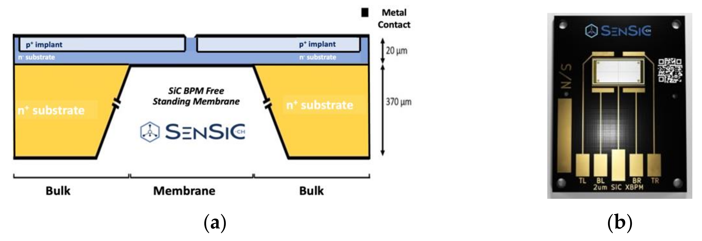
2.1.1. Novel SiC Detectors

The device structures used for the realization of a SiC sensor, produced by SenSic GmbH [19], are based on PIN junctions, i.e., composed by a thin p+, highly doped layer (0.3 um, NA = 1 × 1019 cm−3) on top of a n- low doped layer (ranging from a minimum of 200 nm up to 100 µm, ND = 8 × 1013 cm−3) on top of a n+ thick substrate (370 um, ND = 5 × 1018 cm−3); see Figure 1a. Sensors with different active areas, from 1 × 1 mm2 up to 10 × 10 mm2, and active thicknesses, from 0.2 µm up to 100 µm, have been realized. In particular, the results obtained for the 10 µm thick and 1 × 1 cm2 active area will be shown in this work.
Moreover, the SenSiC company is able to produce the so-called “free-standing membrane” by removing the 370 µm n+ thick substrate using doping selective electrochemical etching as shown in Figure 1a [21,22]. A picture of a developed SiC sensor mounted on a PCB is also shown in Figure 1b.
The use of ultrathin, <20 µm, membranes will reduce beam perturbation, thus being suitable for an in-transmission real-time monitoring of the UHDR beams.
A first characterization of these free-standing membrane sensors, in terms of response as a function of the irradiation temperature and of the radiation damage, has been performed by using low energy proton microbeams (with 1.5 and 3.5 MeV) in the Division of Experimental Physics, Ruder Boškovic’ Institute, showing promising radiation resistance tolerances [23].

2.1.2. Monte Carlo Simulations of the SiC Response

The SiC detector shown in Figure 1, has been simulated using the Monte Carlo Geant4 toolkit [24,25,26] to study the performance of the sensors in terms of energy deposited within the active layer and the produced charge. The use of SiC detectors with very high energy electron (VHEE) beams, i.e., with energy exceeding 100 MeV, has recently become attractive for the treatment of deep tumours with the electron FLASH radiotherapy; it is relevant to investigate the configuration of such sensors in terms of thickness and size suitable for the detection of high energy electrons.
As an example, Figure 2a,b shows the results obtained with the simulations of SiC sensors having a thickness of 2 µm, 5 µm, 10 µm, 15 µm and 20 µm. The energy deposited by 7 MeV, 9 MeV, 100 MeV and 200 MeV electrons in the SiC sensor has been recorded in the simulations to finally calculate the produced charge within the sensor. To have a good compromise between low statistical uncertainties and reasonable computation time, 1 M histories were simulated. To reproduce a realistic case of a dose-to-water deposition of, for instance, 2 Gy, a normalization factor for the total number of histories was retrieved, considering the ratio between the dose deposited for 1 M histories and 2 Gy. This normalization factor is then multiplied for each single energy deposition event for the several configurations of sensor thickness and area used. Afterwards, the total deposited energy for each single configuration was converted to produce a charge through the electron-hole pair production energy, considering their ratio.
As shown in Figure 2a, for the case of 9 MeV and 10 µm thick and 1 × 1 cm2 SiC detector, i.e., corresponding to the configuration experimentally investigated and reported in the manuscript, a total produced charge around 600 nC is produced. For higher energies, i.e., 100 MeV and 200 MeV, in order to have the same signal as the produced charge in the detector active layer, a thickness of at least 20 µm needs to be used. Reducing the detector area down to 2 × 2 mm2 (Figure 2b), a charge signal of about 25 nC is predicted for the configuration studied in the paper (10 µm thickness, 9 MeV), while for the 100 MeV and 200 MeV electron beams, we can see a produced charge ranging from few nC up to 20 nC for a thickness from 2 µm up to 20 µm, respectively.
As an example, Figure 3a reports the simulated distributions of the energy deposited in the 2 µm, 5 µm, 10 µm, 15 µm and 20 µm active thicknesses in the case of 9 MeV mono-energetic beam impinging on the detector surface in vacuum. As expected, the widely obtained energy loss distributions have been fitted using a Gaussian function, as shown in Figure 3a. The resulted values for the centroids and the FWHM are, respectively, 0.62, 1.67, 3.51, 5.4 and 7.4 KeV and 0.73, 1.27, 2.11, 2.97 and 4.00 KeV for the 2 µm, 5 µm, 10 µm, 15 µm and 20 µm active thicknesses.
Monte Carlo simulations have also been used to evaluate the effect of the presence of the substrate behind the active layer with the prospect of using such detectors for the monitoring of the beam. One of the main characteristics and requirements for the beam monitoring is, in fact, the capability of the detector to be “transparent”, avoiding a significant perturbation of the beam in terms of final energy and angular spread. The presence of the bulk substrate traversed by the particles causes a non-negligible angular dispersion and increasing divergence of the incident beam as it is shown in Figure 3b. A 10 µm SiC active layer (simulating the free-standing membrane) and a detector with a total thickness of 500 µm, including the substrate, is simulated considering an incident beam with a mean energy of 9 MeV and input angular distribution shown in Figure 3b (blue points). As can be seen, the angular distribution after the 10 µm-thick SiC detector is very well overlapped with the one of the incident beam, indicating that unsignificant perturbation is provided by the sensor. On the other hand, after the 500 µm-thick detector, the angular distribution results are much wider with a divergence that reaches 20°. This clearly demonstrates that free-standing membranes are fundamental for a practical use of such detectors for beam monitoring under UHDR beams, especially at lower incident energies. Differently, when dealing with VHEE, the presence of the substrate does not heavily affect the angular distribution of the incident electron beam, as expected.

2.2. Experimental Set-Up

2.2.1. Beam Features of the ElectronFLASH Accelerator

The system used for the characterization of the SiC detectors is the ElectronFLASH (EF) LINAC produced by SIT-Sordina company in Italy [27]. The LINAC is operated in electron mode only, with nominal energies ranging between 5 and 12 MeV, and a dose- rate ranging from 0.01 to 4000 Gy/s and higher. Pulse duration can be easily varied according to the user requirement between 1 and 4 µs. The first unit of EF was installed at Orsay Research Center of Institute Curie in 2020; a second one was installed at the University of Antwerp, Belgium; and a third one was recently installed at Centro Pisano Flash RadioTherapy (CPFR) in Pisa, thanks to funding from the Fondazione Pisa [28]. The second machine, which can produce and accelerate electron beams at 7 and 9 MeV, is the one used for performing the SiC detector characterization at UHDRs discussed in this work. The accelerating waveguide concept of the EF is based on the design of IORT-dedicated LINACS previously experienced by SIT staff in [29]. In particular, the wave guide is designed by adopting the radial focusing technique: the electron beam trajectories along the LINAC are directly guided by the electric field of the cavity without any external magnetic solenoid. Moreover, a different approach has been employed for the beam collimation if compared to the standard medical LINAC. Specifically, no thick scattering foil is used: the beam is defocused by means of two quadrupoles, where the gradient can be changed according to the desired field. Such approach shows several advantages for a LINAC operating in FLASH conditions:
  • The absence of the thick scattering foils minimizes the radiation leakage.
  • Large clinical fields can be easily obtained by properly setting the quadrupoles current and magnetic field.
  • The EF system has been designed to work both in FLASH and conventional conditions. The beam current within the single pulse can be varied by choosing between the “FLASH” mode and the “CONVENTIONAL” mode.

2.2.2. Irradiation Configurations and Corresponding Dose per Pulse
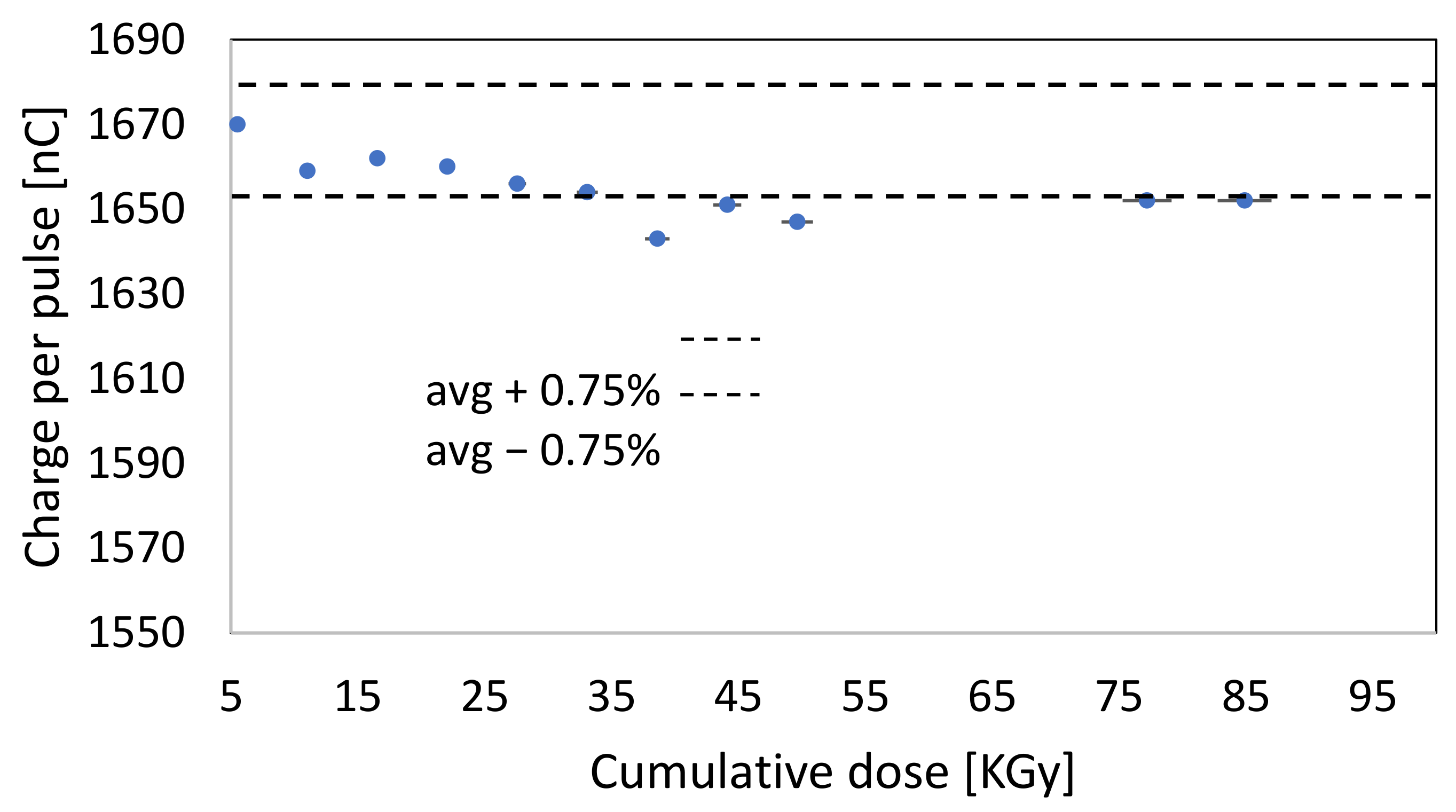
To obtain different dose per pulse values at the irradiation point, a combination of several plastic collimators of different lengths and diameters is used to change the total source to surface distance (SSD). Also, the applicator-to-detector distance (ADD) was varied to obtain different values of dose delivered per pulse. Such collimation system consists of polymethylmethacrylate (PMMA) cylindrical applicators that can be directly attached to the radiant head. Table 1 shows a summary of the configurations used and of the corresponding dose-per-pulse values, measured with RCFs and alanine detectors fixing a pulse duration of 2 µs. A sketch of the experimental setup employed is shown in Figure 4a.
In particular, commercial alanine pellet dosimeters (Gamma-Service, Produktbestrahlung, Radeberg, Germany) (diameter 4.80 ± 0.04 mm, height 2.99 ± 0.02 mm, weight 68.0 ± 0.5 mg, density 1.26 ± 0.02 g/cm3 and mass ratio alanine/binder 0.96/0.04) [30] and radiochromic films EBT-XD type [31] were used to measure the dose delivered per pulse for each geometrical configuration used for the SiC irradiation. Both alanine detectors and RCFs were placed exactly in the same position of the SiC detector using a PMMA phantom as holder. Electron paramagnetic resonance (EPR) measurements were carried out to extract the dose from the irradiated alanine detectors at constant room temperature using a spectrometer ELEXSYS E580 (Bruker, Karlsruhe, Germany) operating at the X-band [32]. A calibration in the dose range from 2.5 to 20 Gy was previously performed with conventional 6MV photon beams produced by the ELEKTA Versa HD linear accelerator to convert the EPR signal in the absorbed dose. Radiochromic films EBT- XD type have been scanned using a flatbed scanner EPSON Expression 11000XL (EPSON central branch Suwa, Japan), and the dose values for each configuration were obtained using FilmQA™ Pro v7 software (Ashland Inc., Wilmington, DE, USA). The batch was previously calibrated in a clinical LINAC (TrueBeam, Varian, Palo Alto, CA, USA) on an electron beam of 9 MeV and dose levels between 0 and 30 Gy, using the calibration procedure recommended by the manufacturer. All the measurements with the SiC, alanine and RCF detectors were performed at the maximum of the depth-dose distribution in water of the 9 MeV electron beam, obtained by placing a 13 mm thick solid water slab sandwiched between the applicator and the detector holder. For some cases, particularly for irradiations at FLASH regimes, one single pulse was necessary to get an acceptable dose in both the RCF and alanine detectors, according to their sensitivity. However, for most other cases, a few pulses were accumulated to get a suitably delivered dose, according to the specific detector sensitivity, with an accelerator frequency ranging between 5 and 100 Hz. The values shown in Table 2 for the conventional regime are then obtained from the total dose delivered divided by the number of accumulated pulses. The dose measurements with alanine and RCF detectors were used as reference measurements and performed just after the SiC irradiation, taking into account that the stability of the LINAC current is under the 2%
The dose transversal profile at the SiC position was also measured with RCF-EBT3 type for each applicator configuration to verify the dose uniformity over the SiC active area (maximum 1 × 1 cm2). Figure 4b shows, as an example, the dose profiles (vertical and horizontal) measured at the SiC position with one of the used applicators, in this case the 40 mm one. As is clearly shown, a flat region of about 15 mm (within 98% percentage dose) and a lateral penumbra (20–80%) of about 7 mm are measured. As the SiC detector has a 1 × 1 cm2 active area, flat profiles over a 15 mm length guarantee a constant dose delivered within the whole SiC active area of 1 × 1 cm2.

3. Results

A 10 μm thick SiC sensor with an active area of 1 × 1 cm2 and 370 µm bulk substrate was characterized to study the response in charge as a function of the applied voltage, using a final applicator of 35 mm diameter, a pulse duration of 2 μs and a pulse frequency of 30 Hz. A Keithley 6517A electrometer was used both to supply the bias voltage and to read the beam charge directly connecting the detector to the electrometer by using a BNC cable. To investigate the dependency of the charge response with the externally applied bias for the most extreme conditions, in terms of delivered dose and consequently produced charge in the active layer of the SiC sensor, a total of 20 pulses have been acquired using the highest beam current and 35 mm applicator (corresponding to about 5 Gy/p). As expected, as long as the applied voltage increases, the response increases in a linear way, reaching a flat region for which the detector response is fairly independent of the applied voltage, indicating full depletion of the sensor-active region. In this region, we can assume that all the produced electron-hole pairs are properly collected. For the SiC detector of 10 μm thickness, which is the one mainly characterized for this experimental campaign, we chose an operational voltage of 480 V, about 50 V above the beginning of the flat region. The response of the 10 μm thick SiC detector 1 × 1 cm2 active area was investigated in terms of increasing dose per pulse, keeping a 2 µs pulse duration fixed (Figure 5a). As described above, different doses per pulse at the irradiation point were obtained by changing the applicator diameter and the distance from the applicator. The dose delivered per pulse at the SiC position for each different configuration was measured with both RCFs and alanine detectors as it is shown in Figure 5a. The SiC response was compared with the response of a commercially available Silicon diode (PTW Dosimetry Diode PR TM60020) of 1 mm2 area and 20 µm thickness and which does not require any applied voltage, irradiated at the same conditions. As shown in Figure 5a, SiC’s response in charge is linear with the dose per pulse up to about 2 Gy/p, in contrast with the Silicon diode which starts to saturate for a dose per pulse around 0.5 Gy/p. The slight under-response of SiCs at higher D/p (visible for the last two points on the right) is probably not due to the sensor saturation itself but likely to the used electrometer that has a limitation in the maximum acceptable peak current. A maximum current of 20 mA is nominally acceptable for the Keithley 6517A, while an instantaneous current of hundreds of mA was produced inside the detector for most of the measurements performed in the FLASH regime. Similar considerations can be done for the UNIDOS electrometer used to acquire the signal of the Silicon diode, although saturation issues of the detector itself cannot be excluded for this case. Indeed, for the latter, a clearer saturation curve can be observed reasonably resulting from both the sensor and the electrometer saturation. Solutions to avoid the overflow of the electrometer are currently under investigation so that if intrinsic limits of the detector in terms of dose per pulse are present and existing at these regimes, these will be clearly investigated.
Besides this study of linearity response at high dose rates, a characterization of the detector radiation hardness was performed to evaluate the leakage current as a function of the accumulated total delivered dose up to 90 KGy, using the 35 mm applicator. Figure 5b shows the leakage current measured after each measurement that was performed using the maximum dose per pulse achievable, i.e., 5 Gy/pulse, and accumulating a total number of 400 pulses at 5 Hz. As can be seen in Figure 5b, no degradation of the sensor, specifically of the signal-to-noise ratio, is observed up to 90 kGy. Additionally, the charge per pulse after each irradiation as a function of the cumulative dose was also measured, as is shown in Figure 6. This study was required to evaluate the radiation hardness of the SiC and, in particular, its response stability after a large amount of accumulated dose. Results in Figure 6 show a variability of the charge per pulse measured with the SiC within the ±0.75% for the explored accumulated dose, which clearly demonstrates the reliability and stability of the SiC performances.

4. Conclusions

This paper reports a first characterization of the novel SiC detectors developed by the STLab company with UHDR 9 MeV electron beams produced by the SIT Sordina ElectronFLASH accelerator.
The response in the charge of a 10 µm thick SiC detector was investigated as a function of the dose delivered per pulse up to 5 Gy/pulse. SiC response was found to be perfectly linear with the dose per pulse up to 2 Gy/pulse, while a slight saturation was found for the dose per pulse higher than 2 Gy/p. This is fully ascribable to the saturation of the used electrometer, while no degradation of the sensor’s response was observed at up to 90 kGy. The results demonstrated, for the first time, the potentialities of Silicon Carbide detectors as possible new dosimeters to employ in FLASH-RT. Nevertheless, the issue related to the saturation of the instrument that has clearly affected the linearity response at higher dose per pulse needs to be addressed in the future employment, for instance, by using an additional electronic circuit to avoid the saturation or by using different instrumentations. New measurements with UHDR electron and proton beams are already planned in the future and will focus on extending the linearity curve up to a higher dose per pulse. Detectors with different active areas and thicknesses will also be tested under the same conditions to investigate their response.
Moreover, the newly developed ultrathin, free-standing membranes will also be experimentally characterized with UHDR beams to confirm the results obtained with the Monte Carlo Geant4 simulation shown in this paper. Thanks to the simulations, we expect that in the case of ultrathin, free-standing sensors without the bulk substrate, a significative reduction on the beam angular scattering and energy degradation will be observed, which will definitively demonstrate their suitability for the UHDR beam monitoring in FLASH-RT.

Author Contributions

Conceptualization, F.R., M.C. and G.M.; methodology, F.R., G.M. (Giuliana Milluzzo), G.F., F.G., G.M. (Giulia Mariani) and M.P.; software, G.M. (Giuliana Milluzzo); data analysis, G.M. (Giuliana Milluzzo), F.R., M.C.D., A.G., M.M., V.V., D.V., E.M., E.S. and A.V.; writing—original draft preparation, F.R. and G.M. (Giuliana Milluzzo); writing—review and editing F.R., G.M. (Giuliana Milluzzo), M.C., F.D.M., A.V., A.G.; supervision, F.R., M.C.; All authors have read and agreed to the published version of the manuscript.

Funding

Partially supported by INFN CSN5 funded project “FRIDA” and by the “SAMOTHRACE” project (ECS00000022) Missione 4 Istruzione e Ricerca-Componente 2-Investimento 1.5 (“PNRR”), NGEU.

Institutional Review Board Statement

Not applicable.

Informed Consent Statement

Not applicable.

Data Availability Statement

Data will be provided on request.

Conflicts of Interest

The authors declare no conflict of interest.

References

  1. Durante, M.; Bräuer-Krisch, E.; Hill, M. Faster and safer? FLASH ultra-high dose rate in radiotherapy. Br. J. Radiol. 2017, 91, 20170628. [Google Scholar] [CrossRef] [PubMed]
  2. Bourhis, J.; Montay-Gruel, P.; Jorge, P.G.; Bailat, C.; Petit, B.; Ollivier, J.; Jeanneret-Sozzi, W.; Ozsahin, M.; Bochud, F.; Moeckli, R.; et al. Clinical translation of FLASH radiotherapy: Why and how? Radiother. Oncol. 2019, 139, 11–17. [Google Scholar] [CrossRef]
  3. Koch, C.J. Re: Differential impact of FLASH versus conventional dose rate irradiation: Spitz et al. Radiother. Oncol. 2019, 139, 62–63. [Google Scholar] [CrossRef] [PubMed]
  4. Schüler, E.; Trovati, S.; King, G.; Lartey, F.; Rafat, M.; Villegas, M.; Praxel, A.J.; Loo, B.W.; Maxim, P.G. Experimental platform for ultra-high dose rate FLASH irradiation of small animals using a clinical linear accelerator. Int. J. Radiat. Oncol. Biol. Phys. 2017, 97, 195–203. [Google Scholar] [CrossRef]
  5. Favaudon, V.; Caplier, L.; Monceau, V.; Pouzoulet, F.; Sayarath, M.; Fouillade, C.; Poupon, M.-F.; Brito, I.; Hupé, P.; Bourhis, J.; et al. Ultrahigh dose-rate FLASH irradiation increases the differential response between normal and tumor tissue in mice. Sci. Transl. Med. 2014, 6, 245ra93. [Google Scholar] [CrossRef] [PubMed]
  6. Montay-Gruel, P.; Bouchet, A.; Jaccard, M.; Patin, D.; Serduc, R.; Aim, W.; Petersson, K.; Petit, B.; Bailat, C.; Bourhis, J.; et al. X-rays can trigger the FLASH effect: Ultra-high dose-rate synchrotron light source prevents normal brain injury after whole brain irradiation in mice. Radiother. Oncol. 2018, 129, 582–588. [Google Scholar] [CrossRef] [PubMed]
  7. Patriarca, A.; Fouillade, C.; Auger, M.; Martin, F.; Pouzoulet, F.; Nauraye, C.; Heinrich, S.; Favaudon, V.; Meyroneinc, S.; Dendale, R.; et al. Experimental set-up for FLASH proton irradiation of small animals using a clinical system. Int. J. Radiat. Oncol. Biol. Phys. 2018, 102, 619–626. [Google Scholar] [CrossRef]
  8. Beyreuther, E.; Brand, M.; Hans, S.; Hideghéty, K.; Karsch, L.; Leßmann, E.; Schürer, M.; Szabó, E.R.; Pawelke, J. Feasibility of proton FLASH effect tested by zebrafish embryo irradiation. Radiother. Oncol. 2019, 139, 46–50. [Google Scholar] [CrossRef]
  9. Romano, F.; Bailat, C.; Jorge, P.G.; Lerch, M.L.F.; Darafsheh, A. Ultra-high dose rate dosimetry: Challenges and opportunities for FLASH radiation therapy. Med. Phys. 2022, 49, 4912–4932. [Google Scholar] [CrossRef] [PubMed]
  10. Vignati, A.; Giordanengo, S.; Fausti, F.; Villarreal, O.A.M.; Milian, F.M.; Mazza, G.; Shakarami, Z.; Cirio, R.; Monaco, V.; Sacchi, R. Beam monitors for tomorrow: The challenges of electron and photon FLASH RT. Front. Phys. 2020, 8, 375. [Google Scholar] [CrossRef]
  11. Petersson, K.; Jaccard, M.; Germond, J.-F.; Buchillier, T.; Bochud, F.; Bourhis, J.; Vozenin, M.-C.; Bailat, C. High dose-per-pulse electron beam dosimetry—A model to correct for the ion recombination in the Advanced Markus ionization chamber. Med. Phys. 2017, 44, 1157–1167. [Google Scholar] [CrossRef] [PubMed]
  12. International Atomic Energy Agency. Absorbed Dose Determination in External Beam Radiotherapy; Technical Reports Series No. 398; IAEA: Vienna, Austria, 2001. [Google Scholar]
  13. McManus, M.; Romano, F.; Lee, N.D.; Farabolini, W.; Gilardi, A.; Royle, G.; Palmans, H.; Subiel, A. The challenge of ionisation chamber dosimetry in ultra-short pulsed high dose-rate very high energy electron beams. Sci. Rep. 2020, 10, 9089. [Google Scholar] [CrossRef]
  14. Gómez, F.; Gonzalez-Castaño, D.M.; Fernández, N.G.; Pardo-Montero, J.; Schüller, A.; Gasparini, A.; Vanreusel, V.; Verellen, D.; Felici, G.; Kranzer, R.; et al. Development of an ultra-thin parallel plate ionization chamber for dosimetry in FLASH radiotherapy. Med. Phys. 2022, 49, 4705–4714. [Google Scholar] [CrossRef] [PubMed]
  15. Di Martino, F.; Giannelli, M.; Traino, A.C.; Lazzeri, M. Ion recombination correction for very high dose-per-pulse high-energy elec tron beams. Med. Phys. 2005, 32, 2204–2210. [Google Scholar] [CrossRef] [PubMed]
  16. Di Martino, F.; Del Sarto, D.; Barone, S.; Giuseppina Bisogni, M.; Capaccioli, S.; Galante, F.; Gasparini, A.; Mariani, G.; Masturzo, L.; Montefiori, M.; et al. A new calculation method for the free electron fraction of an ionization chamber in the ultra-high-dose-per-pulse regimen. Phys. Med. 2022, 103, 175–180. [Google Scholar] [CrossRef]
  17. Di Martino, F.; Del Sarto, D.; Giuseppina Bisogni, M.; Capaccioli, S.; Galante, F.; Gasperini, A.; Linsalata, S.; Mariani, G.; Pacitti, M.; Paiar, F.; et al. A new solution for UHDP and UHDR (Flash) measurements: Theory and conceptual design of ALLS chamber. Phys. Med. 2022, 102, 9–18. [Google Scholar] [CrossRef]
  18. Marinelli, M.; Giuliano, L.; Vanreusel, V.; Felici, G.; Heinrich, S.; Verellen, D.; Galante, F.; Pacitti, M.; Verona, C.; Gasparini, A.; et al. Design, realization, and characterization of a novel diamond detector prototype for FLASH radiotherapy dosimetry. Med. Phys. 2022, 49, 1902–1910. [Google Scholar] [CrossRef]
  19. De Napoli, M. SiC detectors: A review on the use of silicon carbide as radiation detection material. Front. Phys. 2022, 10, 898833. [Google Scholar] [CrossRef]
  20. Lebedev, A.A.; Kozlovski, V.V.; Davydovskaya, K.S.; Levinshtein, M.E. Radiation hardness of silicon carbide upon high-temperature electron and proton irradiation. Materials 2021, 14, 4976. [Google Scholar] [CrossRef]
  21. STLab srl, (Catania, Italy). 2020. Available online: https://www.stlab.eu (accessed on 14 February 2023).
  22. SenSiC GmbH, (Villigen, Switzerland). 2021. Available online: https://www.sensic.ch (accessed on 14 February 2023).
  23. Medina, E.; Sangregorio, E.; Crnjac, A.; Romano, F.; Milluzzo, G.; Vignati, A.; Jakšic, M.; Calcagno, L.; Camarda, M. Radiation hardness study of Silicon Carbide sensors under high temperature proton beam irradiations. Micromachines 2022, 14, 166. [Google Scholar] [CrossRef]
  24. Agostinelli, S.; Allison, J.; Amako, K.A.; Apostolakis, J.; Araujo, H.; Arce, P.; Asai, M.; Axen, D.; Banerjee, S.; Barrand, G.; et al. GEANT4—A simulation toolkit. Nucl. Instrum. Meth. A 2003, 506, 250–303. [Google Scholar] [CrossRef] [Green Version]
  25. Allison, J.; Amako, K.; Apostolakis, J.E.A.; Araujo, H.A.; Dubois, P.A.; Asai, M.A.; Barrand, G.; Capra, R.; Chauvie, S.; Chytracek, R.; et al. Geant4 developments and applications. IEEE Trans. Nucl. Sci. 2006, 53, 270–278. [Google Scholar] [CrossRef] [Green Version]
  26. Allison, J.; Amako, K.; Apostolakis, J.; Arce, P.; Asai, M.; Aso, T.; Bagli, E.; Bagulya, A.; Banerjee, S.; Barrand, G.; et al. Recent developments in GEANT4. Nucl. Instrum. Meth. A 2016, 835, 186–225. [Google Scholar] [CrossRef]
  27. S.I.T.—Sordina IORT Technologies, S.p.A. Available online: https://www.soiort.com (accessed on 14 February 2023).
  28. Di Martino, F.; Barca, P.; Barone, S.; Bortoli, E.; Borgheresi, R.; De Stefano, S.; Di Francesco, M.; Faillace, L.; Giuliano, L.; Grasso, L.; et al. FLASH radiotherapy with electrons: Issues related to the production, monitoring and dosimetric characterization of the beam. Front. Phys. 2020, 8, 570697. [Google Scholar] [CrossRef]
  29. Felici, G.; Barca, P.; Barone, S.; Bortoli, E.; Borgheresi, R.; De Stefano, S.; Di Francesco, M.; Grasso, L.; Linsalata, S.; Marfisi, D.; et al. Transforming an IORT Linac Into a FLASH Research Machine: Procedure and dosimetric characterization. Front. Phys. 2020, 8, 374. [Google Scholar] [CrossRef]
  30. Marrale, M.; Carlino, A.; Gallo, S.; Longo, A.; Panzeca, S.; Bolsi, A.; Hrbacek, J.; Lomax, T. EPR/alanine dosimetry for two therapeutic proton beams. In Nuclear Instruments and Methods in Physics Research, Section B: Beam Interactions with Materials and Atoms; Elsevier: Amsterdam, The Netherlands, 2016; Volume 368, pp. 96–102. [Google Scholar]
  31. Jaccard, M.; Petersson, K.; Buchillier, T.; Germond, J.F.; Durán, M.T.; Vozenin, M.C.; Bourhis, J.; Bochud, F.O.; Bailat, C. High dose-per-pulse electron beam dosimetry: Usability and dose-rate independence of EBT3 Gafchromic films. Med. Phys. 2017, 44, 725–735. [Google Scholar] [CrossRef] [PubMed]
  32. Marrale, M.; Brai, M.; Gennaro, G.; Triolo, A.; Bartolotta, A. Improvement of the LET sensitivity in ESR dosimetry for γ-photons and thermal neutrons through gadolinium addition. Radiat. Meas. 2007, 42, 1217–1221. [Google Scholar] [CrossRef]
Figure 1. Schematic overview (a) and picture (b) of a SiC detector developed by the SenSiC company. As an example, a SiC sensor with 20 µm active thickness and the 370 µm substrate is shown along with the possible “free standing membrane” configuration where the substrate is removed.
Applsci 13 02986 g001
Figure 2. Produced charge within a 1 × 1 cm2 (a) and 2 × 2 mm2 (b) SiC detector for electron beams of 7 MeV, 9 MeV, 100 MeV and 200 MeV delivering an equivalent dose in water of 2 Gy. Results are obtained by means of Monte Carlo Geant4 simulations for SiC active thicknesses of 2 µm, 5 µm, 10 µm, 15 µm and 20 µm.
Applsci 13 02986 g002
Figure 3. (a) Distribution of the energy deposited in the detector active layer for the five geometrical configurations under study with 9 MeV electron incident beam. Gaussian fit performed on the different distributions are also shown. (b) Angular distribution obtained after 10 µm thick (purple line) and 500 µm thick (black line) SiC detector traversed by a 9 MeV electron beam having an initial angular distribution shown in the figure with the blue line.
Applsci 13 02986 g003
Figure 4. (a) Sketch of the experimental setup indicating the source to distance surface (SSD) and the applicator to detector distance (ADD) that is reported in Table 2. (b) Dose transversal profiles measured with an RCF-EBT3 detector.
Applsci 13 02986 g004
Figure 5. (a) SiC response measured with the Keithley 6517A electrometer as a function of the dose per pulse measured with the RCF and the alanine detectors placed in the same location of the detectors. Cross comparison with a commercially available Silicon diode from PTW is also shown. (b) Leakage current of the SiC detectors after each irradiation and average current detected as a function of the cumulative dose delivered at the SiC position.
Applsci 13 02986 g005
Figure 6. Charge per pulse measured with the SiC detector after each irradiation as a function of the cumulative dose. The dotted lines delimit the region within the ± 0.75% variation in charge.
Applsci 13 02986 g006
Table 1. 4H-SiC characteristics compared to Si and diamond. The table has been adapted from [19].
Si4H-SiCDiamond
Atomic number [Z]1414/66
Density [g/cm3]2.333.223.51
Relative permittivity11.99.75.7
Energy gap [eV]1.123.235.5
e-h pair creation energy [eV]3.67.6–8.413
Displacement Energy [eV]13–1530–4043
Electron mobility [cm2/Vs]14508001800
Table 2. Irradiation conditions and correspondent dose per pulse for different applicators and distances from them for 9 MeV electron beams. As evident from the fist column, only for the 10 cm collimator different distances of the detectors from the final part of the applicator (ADD) were explored.
Applicator Diameter [cm]Applicator to Detector Distance (ADD) [cm]D/p RCF
[Gy]
D/p Alanine [Gy]
3.500.080.08
CONVENTIONAL400.030.02
500.070.07
1200.080.08
3.505.27 ± 0.135.05 ± 0.07
404.59 ± 0.114.42 ± 0.05
1001.77 ± 0.041.77 ± 0.02
FLASH10281.04 ± 0.021.08 ± 0.01
10560.59 ± 0.010.6 ± 0.01
121110.21 ± 0.010.22 ± 0.01
Disclaimer/Publisher’s Note: The statements, opinions and data contained in all publications are solely those of the individual author(s) and contributor(s) and not of MDPI and/or the editor(s). MDPI and/or the editor(s) disclaim responsibility for any injury to people or property resulting from any ideas, methods, instructions or products referred to in the content.

