Article

Predictive Energy Management Strategy for Hybrid Electric Air-Ground Vehicle Considering Battery Thermal Dynamics

1
Electrical Engineering, Yanshan University, Qinhuangdao 066004, China
2
School of Mechanical Engineering, Beijing Institute of Technology, Beijing 100081, China
*
Author to whom correspondence should be addressed.
Appl. Sci. 2023, 13(5), 3032; https://doi.org/10.3390/app13053032
Submission received: 7 January 2023 / Revised: 6 February 2023 / Accepted: 24 February 2023 / Published: 27 February 2023
(This article belongs to the Special Issue Frontiers in Hybrid Vehicles Powertrain)

Abstract

:
Hybrid electric air-ground vehicles (HEAGVs), which can run on the land and fly in the air, are considered a promising future transportation. The operation of HEAGVs, accompanied by high energy consumption, could lead to increasing battery temperature, which may affect the lifespan of the battery. To make the battery last longer and improve energy efficiency, an effective energy management strategy (EMS) is necessary for the operation of HEAGVs. In this regard, this paper proposes a predictive EMS based on model predictive control (MPC). Firstly, speed information is obtained by intelligent network technology to achieve a prediction of power demand, and then the state of charge (SOC) reference trajectory is planned. Secondly, a Pontryagin’s minimum principle-based model predictive control (PMP-MPC) framework is proposed, including battery thermal dynamics. Under the framework, fuel efficiency is improved by reducing the temperature of the battery. Finally, the proposed method is compared to PMP, dynamic programming (DP), and rule-based (RB) methods. The effect of different preview horizon sizes on fuel economy and battery temperature is analyzed. Verification results under two driving cycles indicate that compared with the rule-based method, the proposed method improves fuel economy by 5.14% and 5.2% and decreases the temperature by 5.9% and 4.9%, respectively. The results demonstrate that the proposed PMP-MPC method can effectively improve fuel economy and reduce temperature.

1. Introduction

It is acknowledged that the existing traditional vehicles present challenges in contexts of traffic congestion and complex working conditions, such as bridge cutoff, mountain range, and fire rescue [1]. Air-ground vehicles (AGVs) are expected to provide a plausible solution to the above issues, which are gaining increasing attention from the aviation and automotive fields [2]. AGVs require a huge amount of energy when converting between driving and flying, especially in flight mode [3]. High fuel consumption, together with carbon emissions and environmental pollution, is one of the key weaknesses of traditional AGVs. With the development of electrical technology, AGVs are using electrical energy; however, the energy density of the on-board battery is too low and there is a range anxiety problem. The hybrid powertrain could solve the above problems to become the most suitable choice.
The past few decades have witnessed tremendous effort toward hybrid unmanned aerial vehicles and aircraft. Hybrid powertrain has received wide research attention and gradually become a research hotspot [4,5]. Hybrid powertrain can be divided into series, parallel, and series-parallel. In this case, the series configuration allows the coupling of multiple energy sources in the form of electrical energy. The series hybrid unit is electrically connected to the load. The structure of multi-rotor AGVs is characterized by symmetrical distribution around the motor propellers. By using a series architecture to design the hybrid powertrain, each motor-propeller unit can be controlled individually. The rotor and engine are not mechanically connected but electrically connected, and the space structure is relatively simple. Series hybrid electric air-ground vehicles (HEAGVs) are available as an optional solution.
Rational distribution of power between the engine-generator set and the battery can improve the fuel economy of HEAGV, which is the main task of the energy management strategy (EMS). EMSs are divided into rule-based (RB) strategies and optimization-based strategies. RB EMSs rely on personnel experience, which makes it difficult to ensure optimal control is achieved. There are two kinds of rule-based EMSs, based on the logical threshold EMSs [6] and fuzzy EMSs [7]. The EMS based on logic threshold has the advantage of simple control logic. There are two types of optimization-based control strategies: global optimization control and real-time optimization control [8]. To obtain globally optimal results, global optimization algorithms such as dynamic programming (DP) [9] and Pontryagin’s minimum principle (PMP) [10] are used to solve the problem. DP can achieve the optimal global solution; however, sometimes a large amount of calculation leads to dimensional disaster. Liu et al. [11] used the DP method to determine the best torque distribution scheme for the whole driving cycle in the form of segmented decision making. The PMP method is also a global optimization method and is often considered an alternative to DP. DP can be used as a benchmark for other algorithms. However, these algorithms require complete driving cycle information in advance and are computationally intensive. These methods cannot be applied online and in real time. The equivalent consumption minimization strategy (ECMS) is a real-time optimization algorithm [12]. However, the equivalent factor is susceptible to the driving cycle, and the optimal control results take work to obtain. The model predictive control (MPC) method can be regarded as a combination of global and real-time optimization methods. Zhang et al. [13] proposed an exponentially varying speed prediction method based on MPC for power allocation. Based on deep learning methods, Wei et al. [14] developed a set success rate predictor consisting of input state classification and sub-predictors. Intelligent network technology, combined with a variety of advanced technologies, establishes connections between vehicles, drivers and road conditions, which is an effective means of solving EMS problems. Considering future traffic information, Azadi et al. [15] proposed a vehicle automatic cruise control system to reduce red light parking time and fuel consumption. Rajkumar [16] obtained the speed limit and road topography information as constraints for MPC speed prediction through intelligent network technology and calculated the safe speed as a reference. Lorenzo [17] planned the speed curve based on V2X and tested the communication between controllers and intelligent transportation systems (ITS) over cellular networks.
For a hybrid powertrain, the battery pack is a critically important part. Lower battery temperature inhibits battery discharge capacity. High battery temperature affects the battery life and has an impact on the stable operation of HEAGV. Tang et al. [18] added the battery temperature as an optimization term to the cost function, which can achieve a balance between economy and battery aging. Wang et al. [19] illustrated the enhancement mechanism of the thermal conductivity of composite phase change materials from the perspective of microstructure evolution. Ali Asef et al. [20] proposed a novel battery heat dissipation model to model and optimize battery thermal management for series hybrid electric vehicles under different standard driving cycles. Zhang et al. [21] reviewed the battery thermal management methods and compared the advantages and disadvantages of each method. Rodrigo et al. [22] proposed a new definition of the operating point for discharging Li-ion batteries based on degradation, autonomy, and heat generation to maximize battery life. Harrison and Charles [23] predicted the thermal performance and thermal runaway risk of the battery pack during electric vertical takeoff and landing operation through multi-physics field system simulations. Battery temperature is also very important for HEAGVs. Current EMSs that consider the thermal dynamics of the battery in HEAGVs are less researched. Therefore, there is still room for improvement in EMSs.
The SOC reference trajectory in hybrid electric vehicles is important for the MPC of EMSs and has been investigated by several researchers. Zhou et al. [24] aimed to divide the driving cycle into multiple segments and determine the reference SOC trajectory for each segment by a simple analytical formula. Guo et al. [25] used Q-learning to quickly plan the optimal SOC reference. He et al. [26] used DDPG to plan SOC reference trajectory adaptively and quickly. However, the driving cycles of HEAGV include air and ground phases, and the SOC reference trajectory is different from that of hybrid electric vehicles. When HEAGV is operating on the ground, the engine-generator set charges the battery, and the SOC curve tends to rise in preparation for the flight mode. When HEAGV is flying in the air, it consumes much electrical energy. The SOC changes drastically and shows a downward trend. Under the mode transition, the SOC reference trajectories in the two modes are different and segmented for planning. Therefore, it is necessary to plan the SOC reference trajectory of HEAGV.
To bridge these gaps, this paper proposes an MPC-based EMS considering battery thermal dynamics. This paper has the following contributions. First, speed information is obtained through intelligent network technology to achieve the prediction of demand power, and then the SOC reference trajectory is planned in segments. Second, a PMP-MPC EMS framework is proposed. Third, the thermal dynamics of the battery are considered within the PMP-MPC framework. Finally, the effectiveness and superiority of the proposed HEAGV control strategy are verified by comparing them with different methods.
The rest of this paper is as follows. In Section 2, the series hybrid powertrain model is established, including the battery thermal model. In Section 3, the PMP-MPC framework is described, which includes speed acquisition through intelligent network technology, and then the SOC reference trajectory is planned. Finally, the conclusion is summarized.

2. Descriptions of HEAGV with Series Hybrid Powertrain

This study was conducted on a HEAGV with a series hybrid electric propulsion system, as shown in Figure 1. HEAGV has two modes (flight mode and ground mode), which can be switched freely. The series hybrid power system comprises a turboshaft engine, battery packs, a generator, four hub motors, and sixteen rotor motors. The turboshaft engine is completely decoupled from the drive system and can run under its best working conditions to achieve high efficiency. The engine generator set and battery packs are power sources for the hub and rotor motors. Eight pairs of coaxial rotors are used to generate lift in the flight mode of the HEAGV. In ground mode, the HEAGV is propelled by hub motors like a vehicle. The parameters of HEAGV are shown in Table 1.

2.1. Air-Ground Vehicle Model

When HEAGV is driving on the ground, according to the vehicle longitudinal dynamics, the power demand of each wheel can be calculated as follows.
T w = 0.25 [ m g f c o s θ + 0 . 5 A C d ρ a i r v 2 + m g s i n θ + δ m d v d t ] r
where m denotes the air-ground vehicle mass, g refers to the gravity acceleration, f denotes the rolling resistance coefficient, θ represents the slope of the road, A stands for the fronted area, C d shows the air drag coefficient, ρ a i r is the air density, v is the vehicular speed, δ is the mass factor caused by the rotating inertia of wheels and powertrain rotating components, r is the wheel radius, v is the HEAGV’s speed along the longitudinal direction. In addition, the hub motor, and mechanical brakes together provide the torque required by the wheels, and the powertrain torque balance can be expressed as
T w = η T s i g n ( T m ) T m + T b
where η T and T m are transmission efficiency and hub motor torque, respectively. Since there is no reduction mechanism, the transmission efficiency is set to 1.
When the HEAGV is flying in the air, according to flight aerodynamics [27], the force F v e r required for vertical flight is composed of the force G , the acceleration resistance F a c c , and the drag force F a i r , the formula of force in vertical flight is expressed as
F v e r = G + ( F a c c + F a i r ) × s i g n ( V v e r ) = m g + ( δ m a v + 1 2 A u C D ρ α V v e r 2 ) × s i g n ( V v e r )
s i g n ( V v e r ) = { 1 ,         climb 1 ,   descend
where δ is the mass factor caused by the rotational inertia of the rotating part, a v is the vertical acceleration speed, A u is the vertical area, C D is the air drag coefficient, ρ α is the density of air, V v e r is the vertical climb/landing velocity.
When the HEAGV is flying horizontally in the air, the force is
F c r u = F h o r 2 + F v e r 2
F h o r = δ m a h o r + 1 2 A f C D ρ α V h o r 2

2.2. Engine Model

The experimental data modeling is simple, the simulation effect is superior, and the dynamic characteristics of the turboshaft engine can be ignored. Therefore, this paper chooses an experimental modeling method to model the turboshaft engine. The engine is controlled to make it operate at a fixed speed. The turboshaft engine fuel consumption map is shown in Figure 2. The instantaneous fuel consumption of the engine is determined by the engine speed and torque as follows
m . f = f ( ω g , T g )
The turbine drives the generator to create electrical power, and its output power P e can be calculated as
P e = ω e T e η e
where ω e , T e and η e are turbine engine rotational speed, torque, and efficiency, respectively.

2.3. Motor/Generator Models

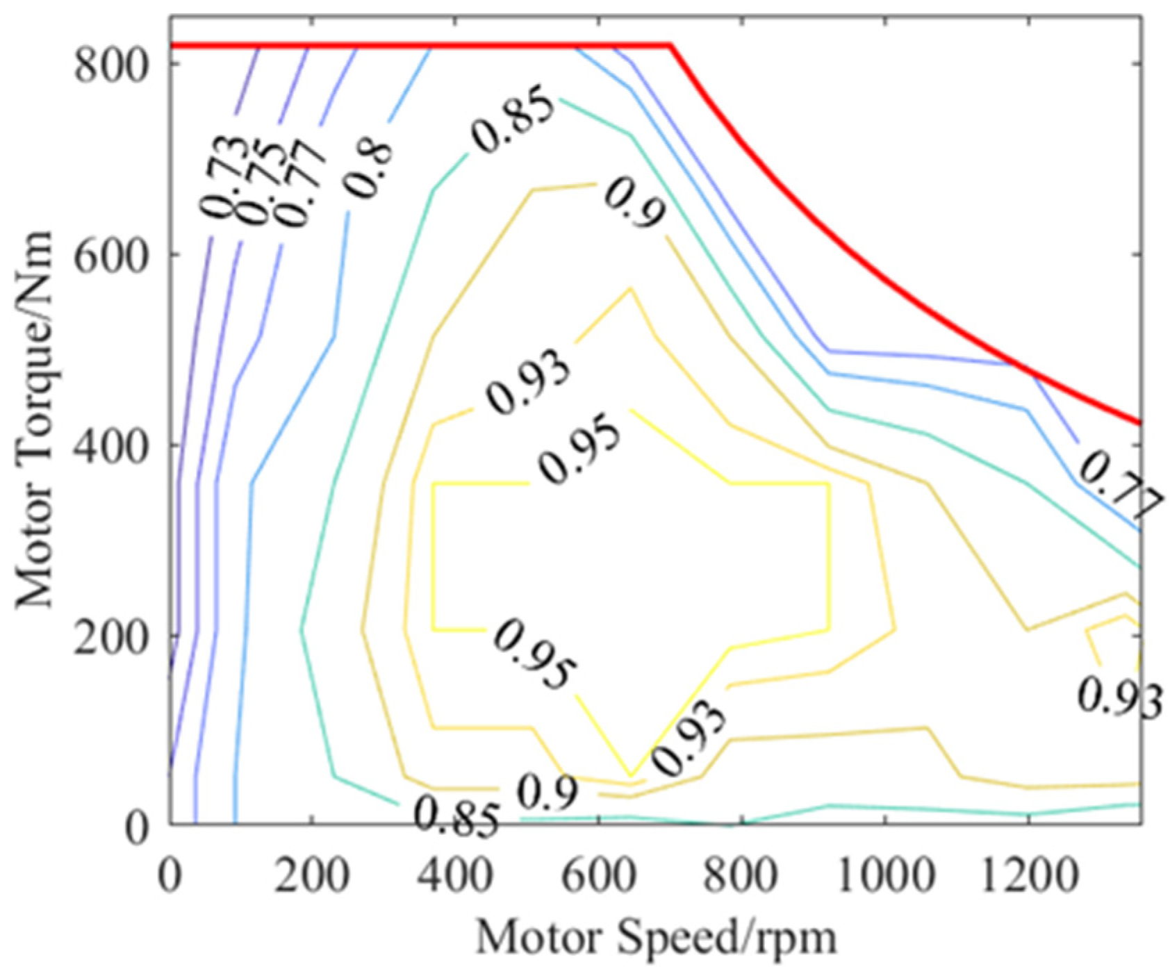
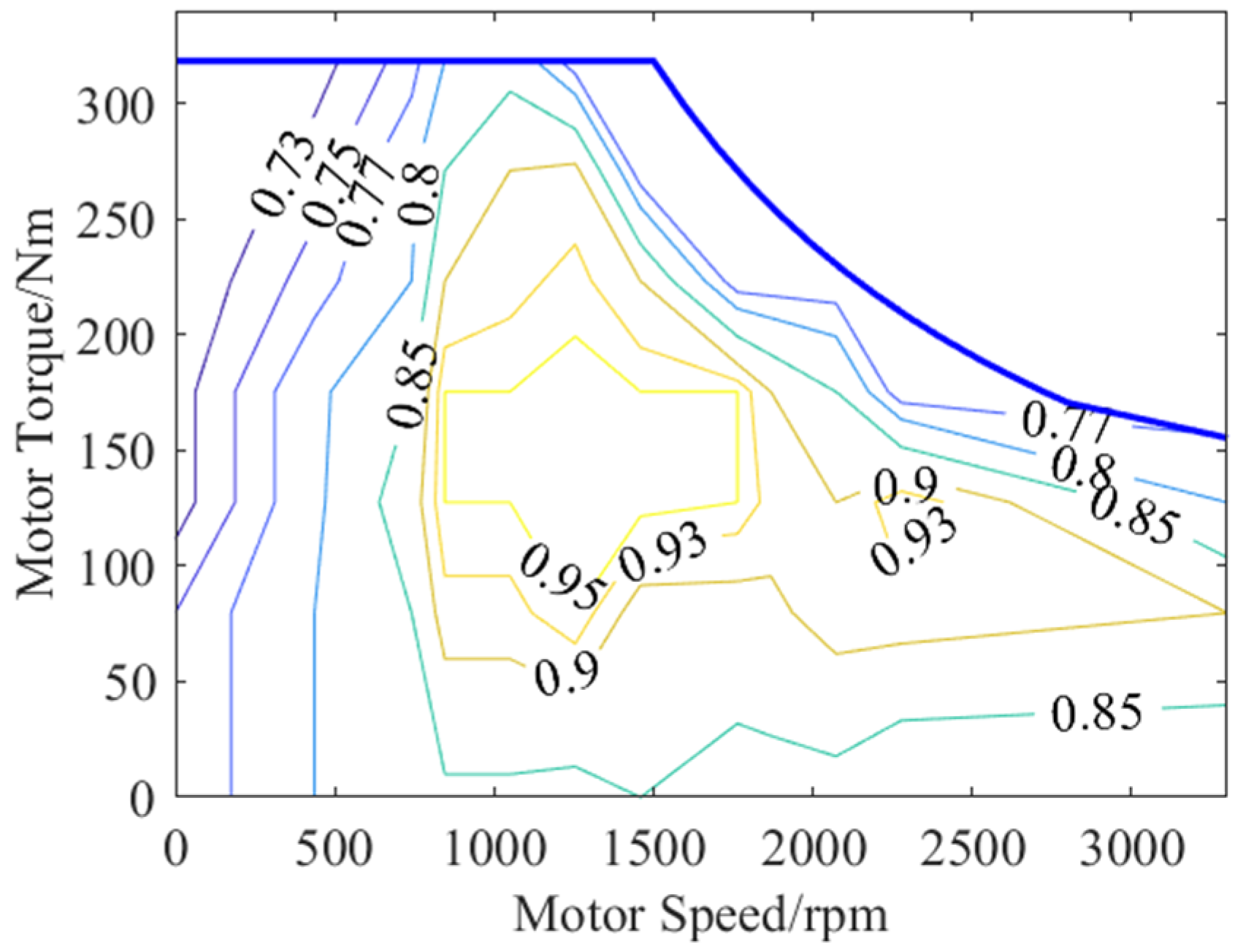
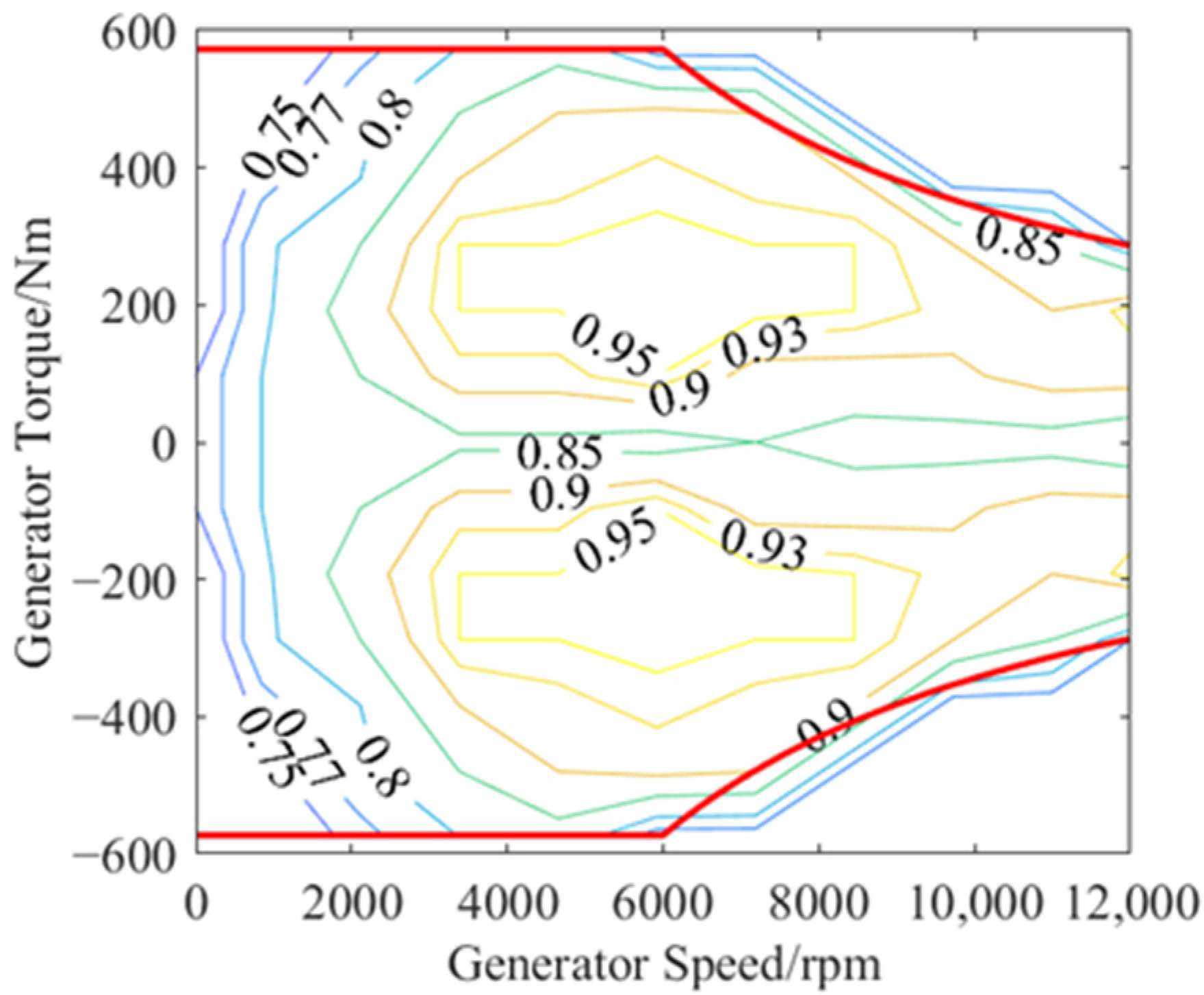
In the powertrain system, the generator is used to provide electrical power. The hub motor and rotor motor drive the wheels and rotor, respectively. The motors and generators are modeled using a quasi-static model. The efficiency characteristics of the motor and generator are represented by nonlinear three-dimensional plots of torque and rotational speed using data obtained from the manufacturer. The motor efficiency plots are represented in Figure 3 and Figure 4, respectively. The generator efficiency plots are represented in Figure 5. The motor efficiency η m at the operation point ( n m , T m ) is calculated according to the following correlation
η m ( n m , T m ) = f ( n m , T m )
η g ( n g , T g ) = f ( n g , T g )
where η m is the motor efficiency, η g is the generator efficiency, n m is the rotating speed of the motor, and n g is the rotating speed of the generation.

2.4. Battery Model

The battery packs are modeled as an equivalent circuit model using the opening circuit voltage U o c and the internal resistance R 0 , which is depicted as
I b a t = U o c U o c 2 4 R 0 P b a t 2 R 0
S O C . = I b a t Q b a t
where I b a t is the battery current, S O C . is the dynamics of the battery SOC, and Q b a t is the battery normal capacity. Temperature is an important factor that affects battery life. To study the thermal management of the battery, the heat production of the battery itself is assumed to be evenly distributed in space. The material of the battery is uniform. The radiant heat produced by the battery is ignored. The effect of flight altitude on battery temperature is not considered. Therefore, the total heat generated by the battery Q is composed of joule heat and reaction heat, which can be expressed as [28]
Q = I 2 r + I T d E d T
where I is the current of the battery cell, r is the internal resistance of the battery cell, T is the temperature of the battery cell, and d E / d T is the temperature influence coefficient of the battery, which is a physical quantity related to electrochemistry [29].
The heat generation rate of the battery is expressed as
q = Q V = ρ C p d T d t
where q is the heat generation rate of the battery, ρ is the average density of the battery, C p is the specific heat capacity of the battery, and d T / d t is the dynamics of the battery temperature.
From Equations (13) and (14), the dynamics of the battery temperature can be obtained:
d T d t = σ I 2 r + I T d E d T ρ C p V
where σ is the heat dissipation influence coefficient, which is related to the heat dissipation system of HEAGV batteries.

3. PMP-MPC Energy Management Strategy for HEAGV

The HEAGV needs a lot of energy to take off vertically, and the hybrid pack and battery work together to provide the power needed. The energy required for level flight is constant. Compared to flight mode, the amount of energy expended on land is relatively small. In this section, a PMP-MPC EMS framework is proposed. First, In the intelligent network environment, HEAGV establishes information interaction with cloud and ground workstations and provides HEAGV with accurate speed information through environment-aware navigation and positioning technologies. Second, in the MPC framework, SOC reference trajectories are required for each prediction horizon, and SOC reference trajectories are segmented and planned. The energy management problem for each prediction horizon can be formulated as a multi-objective multi-constraint nonlinear optimization problem. Finally, the PMP algorithm is used to allocate the power and solve the two-point boundary value problem by the dichotomous method. The overall control framework of the proposed method is shown in Figure 6.

3.1. Speed Information Acquisition

In this paper, intelligent network technology is used to obtain HEAGV speed information, as shown in Figure 6. Through V2V and V2I communication technologies, multi-dimensional connection information is obtained, including the driving status of the vehicle in front and the self-vehicle, as well as traffic signals. HEAGV can use ITS and GPS to obtain traffic information. In addition, sensors such as radar can provide the necessary status of the vehicle. The ground control station interacts with the vehicle and the cloud through wireless communication. Therefore, this effective information can be integrated into EMS to obtain accurate speed information, further improving fuel economy [30].

3.2. SOC Reference Trajectory Planning

If the SOC reference trajectory is appropriate, the optimized performance will be significantly improved in the MPC framework of EMS [31]. SOC decreases roughly linearly with increasing hybrid electric vehicle driving distance. However, the driving cycle of HEAGV includes both air and ground phases. HEAGV has a higher power requirement in flight mode than in ground phases which can lead to a large amount of electrical energy being consumed. If SOC has a linear downward trend, increasing the driving distance may exceed the SOC minimum. Therefore, the SOC reference trajectory of HEAGV is different from that of hybrid vehicles. The high power requirement of HEAGV while in flight mode leads to a large amount of electrical energy being consumed. The battery is discharged, and the SOC is on a decreasing trend. The SOC tends to increase when the HEAGV is in ground mode when the battery is charged to ensure proper travel. Therefore, this paper proposes a fast planning method for global SOC reference trajectory based on traffic information. The ITS system is used to obtain the average speed information of different road sections in the driving route and to segment the different modes of HEAGV. SOC reference trajectory is divided into two types according to the HEAGV working mode. Different formulae calculate the change of SOC of different segments. The SOC reference trajectory segments of HEAGV in flight and ground modes are expressed as follows.
S O C r e f ( k + h p ) = S O C ( k ) L ( k + h p ) L 0 L ( k ) ( S O C ( k ) S O C f )
S O C r e f ( k + h p ) = S O C ( k ) + L ( k + h p ) L 0 L ( k ) ( S O C ( k ) S O C f )
where k is the current time step, h p is the size of preview horizon, v is the actual vehicular speed, v p is the predicted speed in the preview horizon, L ( k ) and L ( k + h p ) indicate the distance traveled up to S O C ( k ) , and S O C ( k + h p ) refers to the initial and final values SOC boundary in a preview horizon.
The SOC reference trajectory is shown in Figure 7. In the first stage, the SOC curve decreases when the HEAGV is in flight mode. In the second stage, the SOC curve rises and HEAGV is charging in ground mode to prepare for the next flight. In the third stage, HEAGV switches to flight mode, consuming a large amount of power, and the SOC curve decreases.

3.3. PMP-MPC Framework

The required power of HEAGV is expressed as
P d e m = P e g + P b a t
where P e g is the power of the engine generator set, and P b a t is the battery power. Reasonable allocation and prediction of P e g and P b a t is the key to achieving excellent performance.
The EMS, based on optimal control theory, seeks to minimize a global criterion over the total length of the trip. The criterion is defined by a cost function, most commonly the fuel consumption only. The cost function proposed in this paper includes the additional cost of battery temperature evolution in addition to fuel consumption. The PMP algorithm is used to solve the minimum energy consumption cost, and the objective function can be defined as
J = t k t k + t p ( J m + J T ) d t = t k t k + t p ( c f m f . + κ d T d t ) d t
where J is total cost function, J m and J T are fuel cost and battery temperature cost, respectively, k is current time step, t p is the length of the prediction horizon, and c f is the prices of fuel. d T / d t is the dynamics of the battery temperature, and κ is a weighting parameter depending on the battery temperature, which is related to battery temperature, as shown in Figure 8. The key to this additional cost is to penalize commands that cause the battery temperature to move away from its slow-aging operating range and to support commands that bring the battery temperature closer. The weighting factor κ will allow a trade-off between fuel consumption and safe battery temperature. There is no additional cost to run the battery at a safe temperature, with κ set to 0. On the other hand, when the temperature is too high, κ increases, and the higher the temperature, the higher the cost to prevent the temperature from rising further. In contrast, when the temperature is too low, the value of κ is negative, which is conducive to heating the battery and making the battery closer to the safe temperature. The optimum temperature range is 10~35 °C [32].
The Hamilton function can be defined as
H = c f m . f + κ d T d t + λ 1 ( t ) S O C . + λ 2 ( t ) T .
where λ 1 ( t ) and λ 2 ( t ) is the co-state variable, the state variable x ( t ) and control variable u ( t ) are shown as
x 1 ( t ) = S O C ( t )
x 2 ( t ) = T ( t )
u ( t ) = P e ( t )
The dynamics of the state and co-state variables can be accounted for as
x . ( t ) = H λ ( t ) = U o c U o c 2 4 R 0 P b a t 2 R 0
λ 1 . ( t ) = H S O C = C f m . f S O C ( κ T . ) S O C λ 1 ( t ) λ S O C . S O C λ 2 ( t ) λ T . S O C
λ 2 . ( t ) = H T = C f m . f T ( κ T . ) T λ 1 ( t ) λ S O C . T λ 2 ( t ) λ T . T
To obtain the global optimal solution, the Hamiltonian function must satisfy the following necessary constraint
H ( x * ( t ) , u * ( t ) , λ * ( t ) , t ) H ( x ( t ) , u ( t ) , λ ( t ) , t )
Furthermore, the state variable must satisfy the following boundary conditions:
S O C ( t k ) = S O C int
S O C ( t k + t p ) = S O C e n d
where S O C int and S O C e n d are the initial and final SOC values of each prediction layer, which are determined by the reference SOC.
Therefore, the optimal control sequence can be expressed as
P e * = a r g m i n H ( x ( t ) , u ( t ) , λ ( t ) , t )
The physical constraints on state variables and control variables can be given as
n e _ min n e n e _ max
T e _ min T e T e _ max
P e _ min P e P e _ max
I b a t _ min I b a t I b a t _ max
S O C min S O C S O C max
where min and max denote the upper and lower boundary values, respectively.
The shooting method is used to solve the two-point boundary problem [33]. The initial costate value is set to λ 0 and the optimal co-state value is obtained by dichotomy in the interval. In order to ensure the calculation efficiency, the maximum iteration number j max is set.

4. Result and Discussion

In this section, the simulation results demonstrate the performance of the proposed strategy. First, to verify the effectiveness of the proposed control strategy, two driving cycles, which both include the flight phase and the ground phase are used as test driving cycles. Second, the proposed strategy is compared and analyzed with PMP, DP, and RB methods. Finally, the effectiveness of the proposed strategy is verified. Moreover, all the results were calculated on a laptop computer with a 1.60 GHz CPU and 16.00 GB of memory.

4.1. PMP-MPC Framework

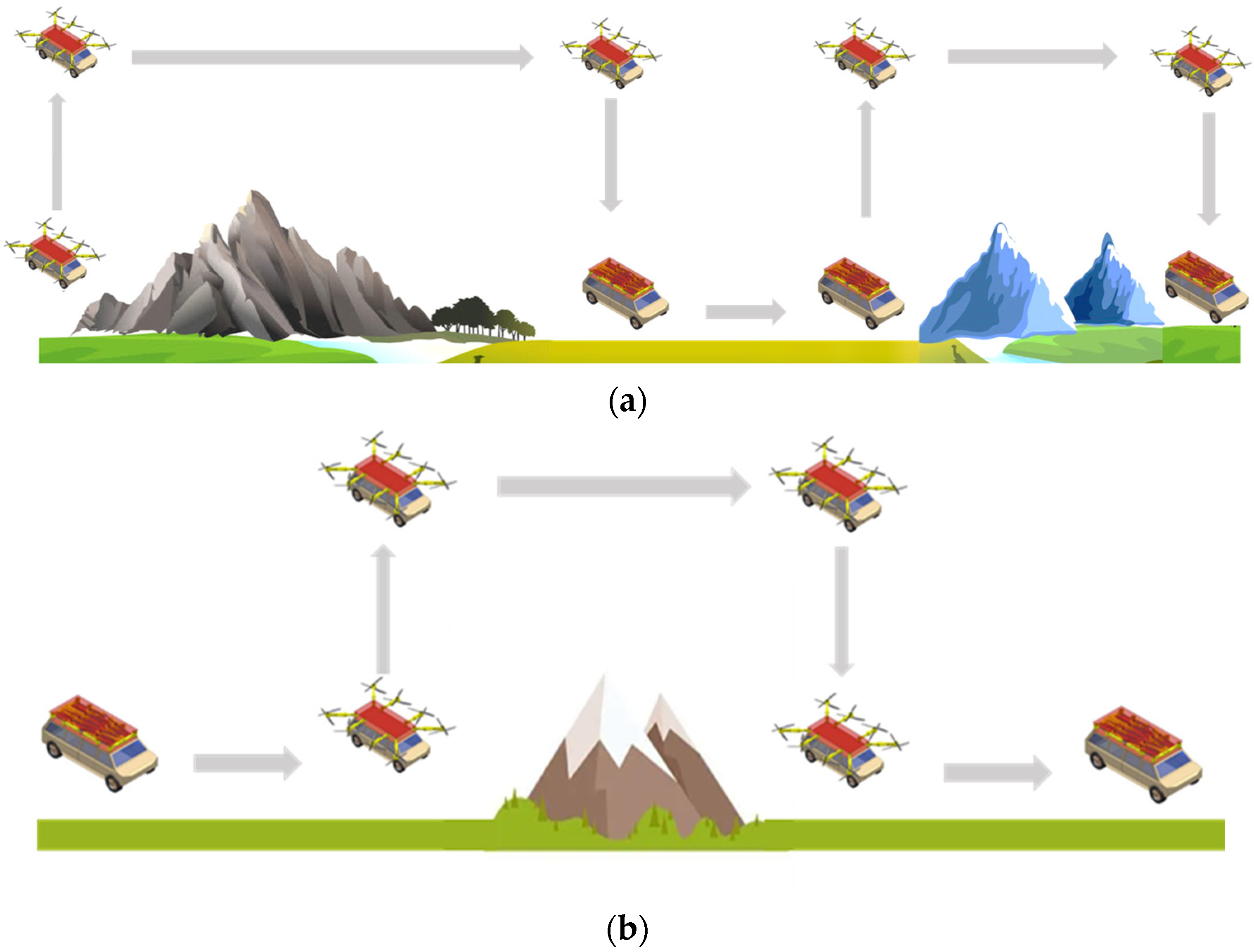
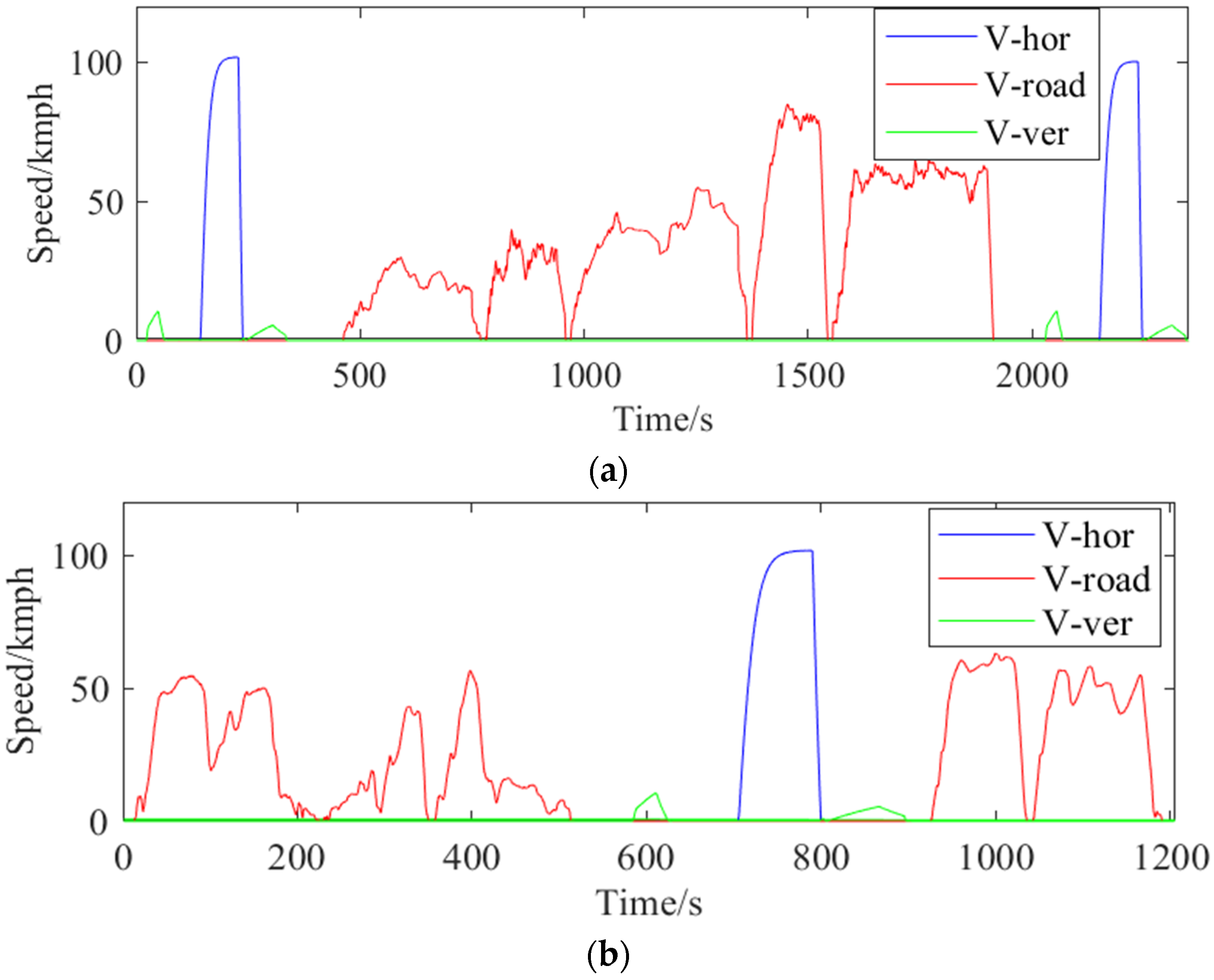
The mission profiles of HEAGV in flight and on the ground under two driving cycles are shown in Figure 9. The first driving cycle A used in this paper consists of two flight phases and one ground phase, totaling 2360 s. To cross obstacles, the HEAGV switches to flight mode. In the first flight stage, HEAGV goes through the vertical takeoff stage, adjusts its attitude to start horizontal flight after reaching a certain altitude, and then completes vertical landing by hovering. In the second stage, the HEAGV switches to ground driving mode. At this stage, the battery needs to accumulate energy to meet the needs of the next flight, and the SOC curve generally shows an upward trend during this process. In the third stage, the HEAGV is used to cross obstacles, just as in the first stage. The second driving cycle B consists of two ground phases and one flight phase for a total of 1205 s. First HEAGV drives from the ground, then switches to flight mode, and finally switches to ground mode. The speed of HEAGV under two driving cycles A and B is shown in Figure 10.

4.2. Comparison of Different Methods

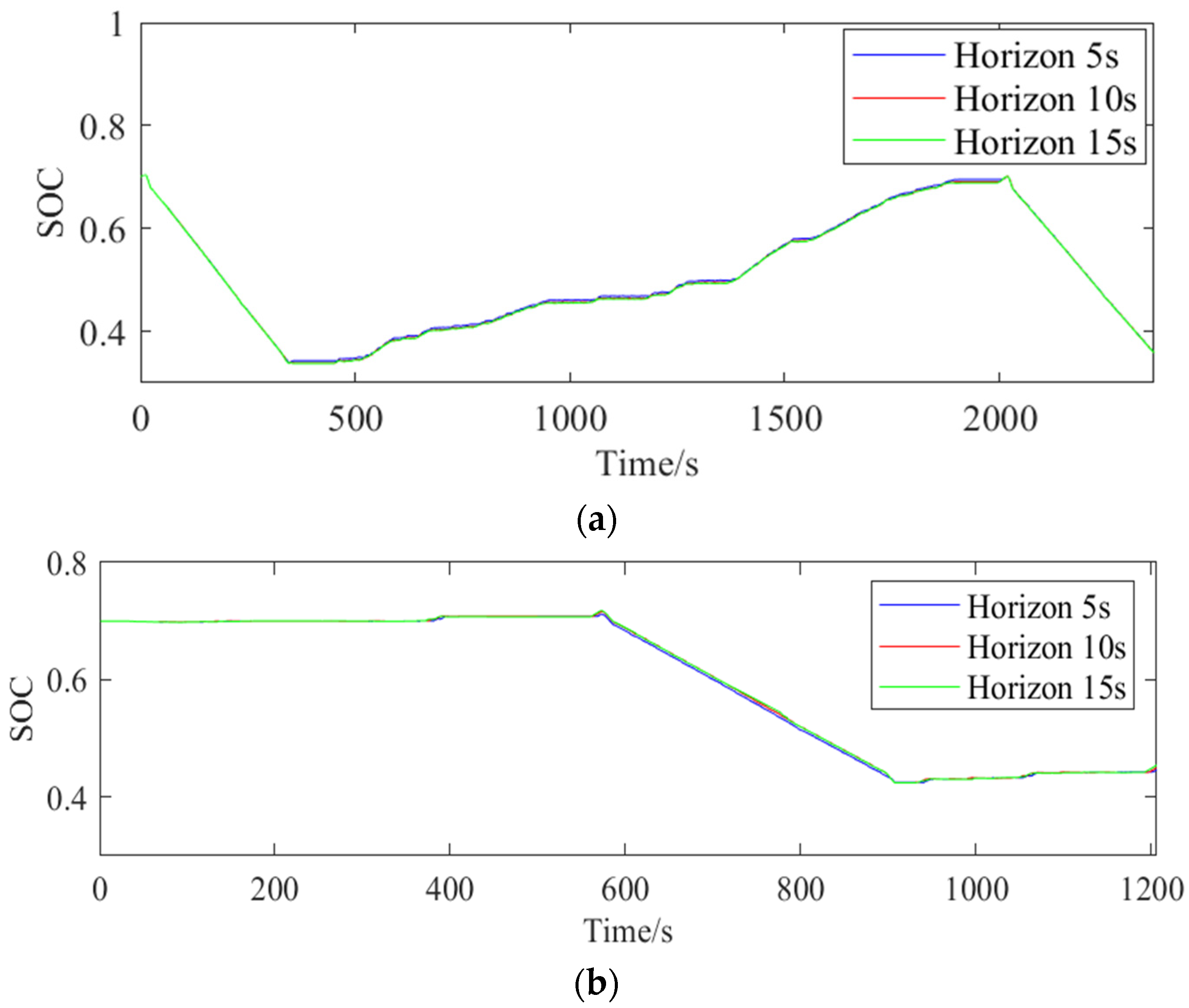
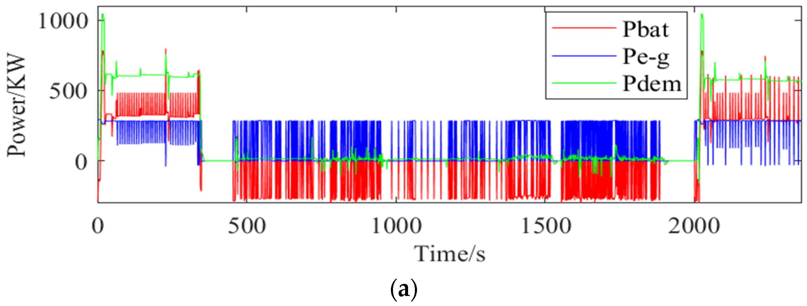
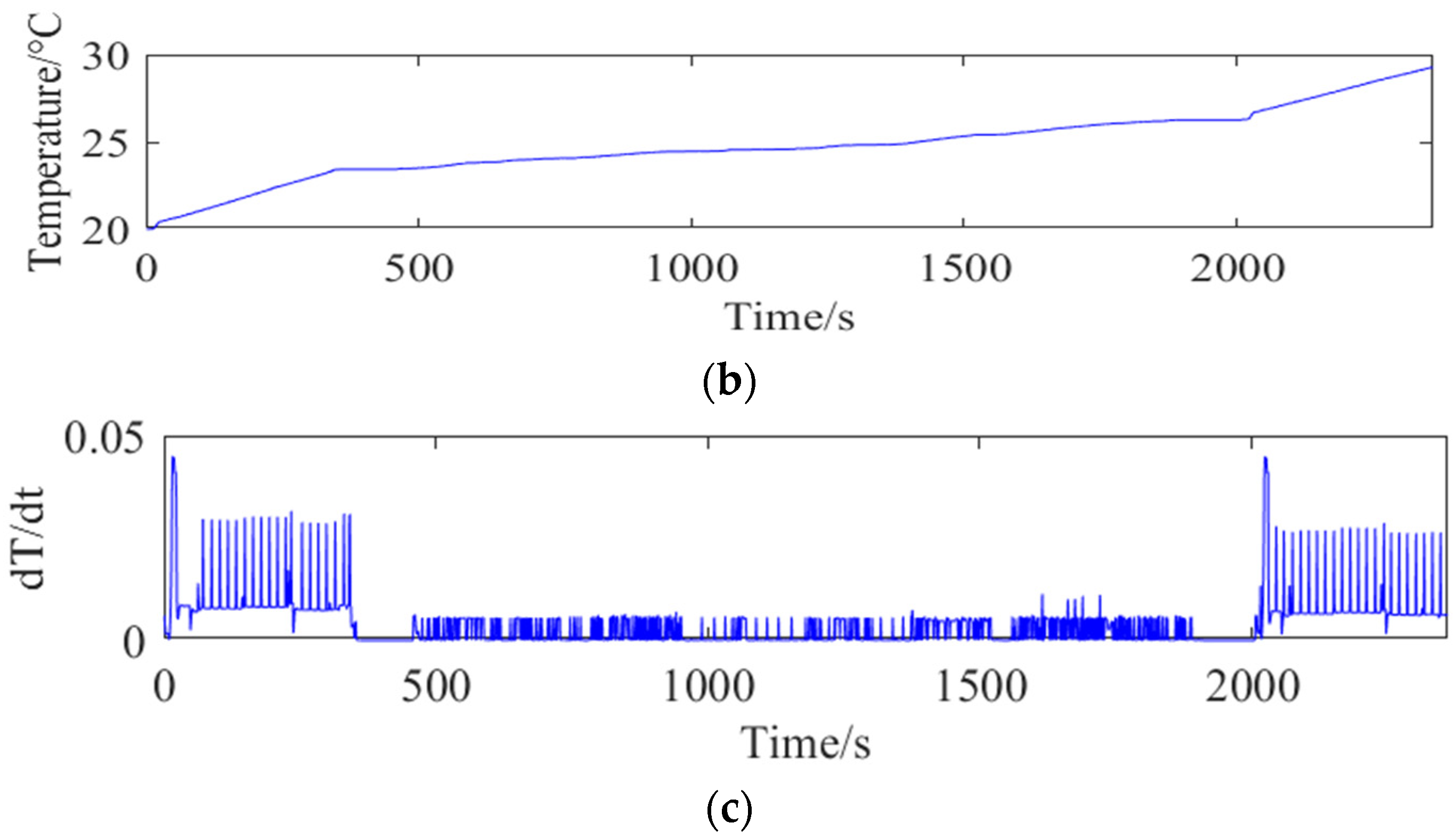
To verify the proposed method, PMP-MPC is compared in different prediction horizons of 5 s, 10 s, and 15 s, as shown in Figure 11. The results of three different prediction horizons are shown in Table 2 and Table 3. The temperature and temperature change rate of the battery in the 5 s prediction horizon are shown in Figure 12 and Figure 13. When the prediction horizon is 5 s, the total cost is the lowest and the best results are obtained. The prediction horizon is too long to affect the accuracy of the prediction. In flight mode, the engine and battery run at high power, and the battery temperature rises faster. When in ground mode the engine runs to charge the battery, and the battery temperature rises slowly. Different driving cycles under the same method have the same curve trend in both flight and ground states, which verifies the reasonableness of the method.
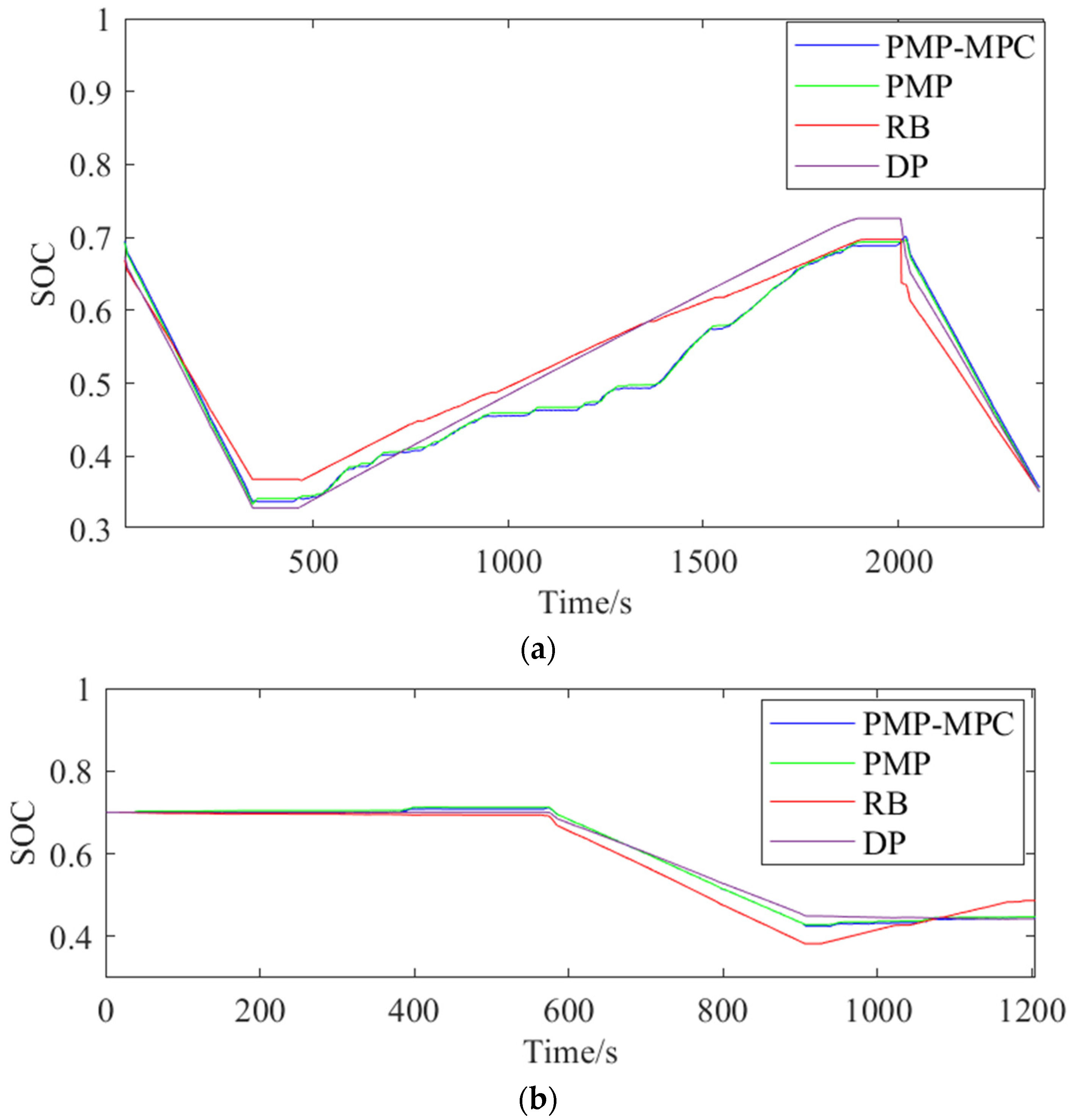
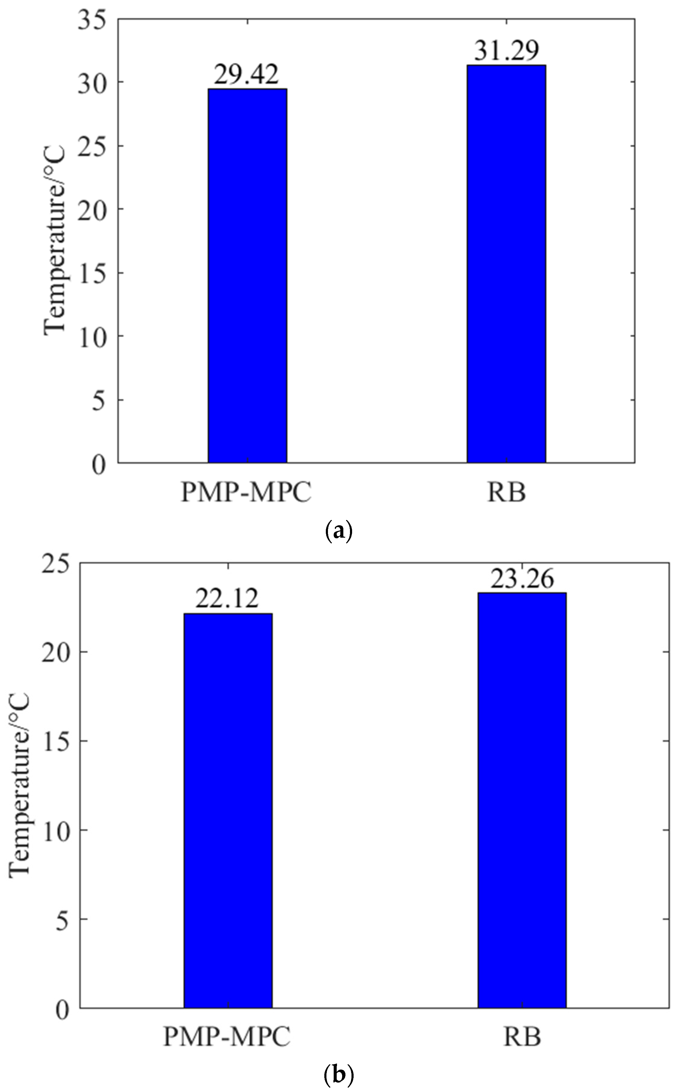
In order to further verify the proposed method, PMP-MPC, DP, PMP, and RB methods are used for comparison. The initial temperature was set at 20 °C. The comparison SOC curve is shown in Figure 14. It can be seen from the figure that SOC curves obtained by these different methods have the same general trend. The SOC curve drops in flight mode and rises in ground mode. The results show that the proposed PMP-MPC method can achieve nearly global optimal results and has the potential of online real-time application. There is a performance improvement compared to the rule-based method. The fuel consumption and battery temperature for the different methods in driving cycles A and B are shown in Figure 15 and Figure 16. Temperature comparison only considers the real-time online method.
The results show that the proposed approach has higher fuel consumption than the global optimization approach because MPC-based EMS is essentially a local optimization algorithm. Overall, the PMP-MPC algorithm may provide a better alternative for developing an efficient and low-cost EMS. In addition, the RB-based method, although capable of online implementation and fast computation, has a significantly higher fuel cost.

5. Conclusions

In this paper, a PMP-MPC method is proposed considering the battery thermal dynamics for HEAGVs. First, speed information is obtained through intelligent network technology to realize the prediction of power demand, and then the SOC reference trajectory is planned in segments. Second, a PMP-MPC EMS is proposed. Third, the effect of battery temperature on total cost is analyzed by considering battery temperature in the PMP-MPC EMS. The resulting EMS optimizes fuel consumption and battery temperature, and the strategy is applicable to the HEAGV. Finally, the proposed method is compared with PMP, DP, and RB to verify its effectiveness. Compared with the rule-based method, the fuel economy improved by 5.14% and 5.2% for both driving cycles a and b, respectively. Temperature costs are also reduced by 5.9% and 4.9%, respectively. Therefore, the proposed PMP-MPC is an effective online method.

Author Contributions

Conceptualization, Z.L., X.J. and C.Y.; methodology, Z.L., X.J. and M.Z.; software, Z.L. and M.Z.; validation, Z.L., X.J. and M.Z.; formal analysis, Z.L., X.J. and M.Z.; investigation, Z.L.; resources, Z.L.; data curation, Z.L.; writing—original draft preparation, Z.L., X.J. and M.Z.; writing—review and editing, Z.L., X.J., M.Z., C.Y. and L.Y.; visualization, Z.L.; supervision, Z.L. and X.J. All authors have read and agreed to the published version of the manuscript.

Funding

This work was supported by the National Natural Science Foundation of China (No. 61973265).

Institutional Review Board Statement

Not applicable.

Informed Consent Statement

Not applicable.

Data Availability Statement

Not applicable.

Conflicts of Interest

The authors declare no conflict of interest.

References

  1. Jordi, P.; Tanja, Z.; Jovana, K. On the understanding of the current status of urban air mobility development and its future prospects: Commuting in a flying vehicle as a new paradigm. Transp. Res. Part E 2022, 166, 102868. [Google Scholar]
  2. Qie, T.; Wang, W.; Yang, C.; Li, Y.; Liu, W.; Xiang, C. A path planning algorithm for autonomous flying vehicles in cross-country environments with a novel TF-RRT∗ method. Green Energy Intell. Transp. 2022, 1, 100026. [Google Scholar] [CrossRef]
  3. Zhao, J.; Yang, C.; Wang, W.; Xu, B.; Li, Y.; Yang, L.; Zhu, H.; Xiang, C. A game-learning-based smooth path planning strategy for intelligent air-ground vehicle considering mode switching. IEEE Trans. Transp. Electrif. 2022, 8, 3142150. [Google Scholar] [CrossRef]
  4. Xie, Y.; He, S.; Savvaris, A.; Tsourdos, A.; Zhang, D.; Xie, A. Convexification in energy optimization of a hybrid electric propulsion system for aerial vehicles. Aerosp. Sci. Technol. 2022, 123, 107509. [Google Scholar] [CrossRef]
  5. Wang, W.; Chen, Y.; Yang, C.; Li, Y.; Xu, B.; Xiang, C. An enhanced hypotrochoid spiral optimization algorithm based intertwined optimal sizing and control strategy of a hybrid electric air-ground vehicle. Energy 2022, 257, 124749. [Google Scholar] [CrossRef]
  6. Huang, K.; Nguyen, M.; Chen, P. A Rule-Based Control Strategy of Driver Demand to Enhance Energy Efficiency of Hybrid Electric Vehicles. Appl. Sci. 2022, 12, 8507. [Google Scholar] [CrossRef]
  7. Yang, C.; Lu, Z.; Wang, W.; Li, Y.; Chen, Y.; Xu, B. Energy management of hybrid electric propulsion system: Recent progress and a flying car perspective under three-dimensional transportation networks. Green Energy Intell. Transp. 2023, 2, 100061. [Google Scholar] [CrossRef]
  8. Liu, K.; Jiao, X.; Yang, C.; Wang, W.; Xiang, C.; Wang, W. Event-Triggered intelligent energy management strategy for plug-in hybrid electric buses based on vehicle cloud optimization. Intell. Transp. Syst. 2020, 14, 1153–1162. [Google Scholar] [CrossRef]
  9. Tang, W.; Wang, Y.; Jiao, X.; Ren, L. Hierarchical energy management strategy based on adaptive dynamic programming for hybrid electric vehicles in car-following scenarios. Energy 2023, 265, 126264. [Google Scholar] [CrossRef]
  10. Zhang, S.; Hu, X.; Xie, S.; Song, Z.; Hu, L.; Hou, C. Adaptively coordinated optimization of battery aging and energy management in plug-in hybrid electric buses. Appl. Energy 2019, 256, 113891. [Google Scholar] [CrossRef]
  11. Liu, J.; Chen, Y.; Zhan, J.; Shang, F. Heuristic Dynamic Programming Based Online Energy Management Strategy for Plug-In Hybrid Electric Vehicles. IEEE Trans. Veh. Technol. 2019, 68, 4479–4493. [Google Scholar] [CrossRef]
  12. Yang, C.; Du, S.; Li, L.; You, S.; Yang, Y.; Zhao, Y. Adaptive real-time optimal energy management strategy based on equivalent factors optimization for plug-in hybrid electric vehicle. Appl. Energy 2017, 203, 883–896. [Google Scholar] [CrossRef]
  13. Zhang, S.; Xiong, R.; Sun, F. Model predictive control for power management in a plug-in hybrid electric vehicle with a hybrid energy storage system. Appl. Energy 2017, 185, 1645–1662. [Google Scholar] [CrossRef]
  14. Wei, Z.; Ma, Y.; Xiang, C.; Liu, D. Power Prediction-Based Model Predictive Control for Energy Management in Land and Air Vehicle with Turboshaft Engine. Complexity 2021, 2021, 2953241. [Google Scholar] [CrossRef]
  15. Asadi, B.; Vahidi, A. Predictive Cruise Control: Utilizing Upcoming Traffic Signal Information for Improving Fuel Economy and Reducing Trip Time. IEEE Trans. Control. Syst. Technol. A Publ. IEEE Control. Syst. Soc. 2011, 19, 707–714. [Google Scholar] [CrossRef]
  16. Deshpande, S.R.; Jung, D.; Bauer, L.; Canova, M. Integrated approximate dynamic programming and equivalent consumption minimization strategy for eco-driving in a connected and automated vehicle. IEEE Trans. Technol. 2021, 70, 11204–11215. [Google Scholar] [CrossRef]
  17. Brunelli, L.; Capancioni, A.; Gonnella, P.; Casadio, R.; Brusa, A.; Cavina, N.; Caggiano, M. A hybrid vehicle hardware-in-the-loop system with integrated connectivity for ehorizon functions validation. IEEE Trans. Veh. Technol. 2021, 70, 4340–4352. [Google Scholar] [CrossRef]
  18. Tang, X.; Jia, T.; Hu, X.; Huang, Y.; Deng, Z.; Pu, H. Naturalistic Data-Driven Predictive Energy Management for Plug-in Hybrid Electric Vehicles. IEEE Trans. Transp. Electrif. 2020, 7, 497–508. [Google Scholar] [CrossRef]
  19. Wang, X.; Li, B.; Qu, Z.; Zhang, J.; Jin, Z. Effects of graphite microstructure evolution on the anisotropic thermal conductivity of expanded graphite/paraffin phase change materials and their thermal energy storage performance. Int. J. Heat Mass Transf. 2020, 155, 119853. [Google Scholar] [CrossRef]
  20. Asef, A.; Chitsaz, I.; Madani, N. Modeling and total cost optimization of battery thermal management system in a hybrid electric vehicle. J. Energy Storage 2022, 172, 104844. [Google Scholar] [CrossRef]
  21. Zhang, X.; Li, Z.; Luo, L.; Fan, Y.; Du, Z. A review on thermal management of lithium-ion batteries for electric vehicles. Energy 2022, 238, 121652. [Google Scholar] [CrossRef]
  22. Pires, R.A.; Carvalho, S.A.; Cardoso Filho, B.J.; Pires, I.A.; Huebner, R.; Maia, T.A. The Assessment of Electric Vehicle Storage Lifetime Using Battery Thermal Management System. Batteries 2023, 9, 10. [Google Scholar] [CrossRef]
  23. Harrison, J.; Charles, D.; Zenker, J.; Frank, E. Using multi-physics system simulation to predict battery pack thermal performance and risk of Thermal runaway during eVTOL aircraft operations. In Proceedings of the 2019 AIAA/IEEE Electric Aircraft Technologies Symposium (EATS), Indianapolis, IN, USA, 22–24 August 2019. [Google Scholar]
  24. Zhou, W.; Chen, Y.; Zhai, H.; Zhang, W. Predictive Energy Management for a Plug-in Hybrid Electric Vehicle Using Driving Profile Segmentation and Energy-based Analytical SoC Planning. Energy 2020, 220, 119700. [Google Scholar] [CrossRef]
  25. Guo, L.; Zhang, X.; Zou, Y.; Guo, N.; Li, J.; Du, G. Cost-optimal energy management strategy for plug-in hybrid electric vehicles with variable horizon speed prediction and adaptive state-of-charge reference. Energy 2021, 232, 120993. [Google Scholar] [CrossRef]
  26. He, H.; Huang, R.; Meng, X.; Zhao, X.; Wang, Y.; Li, M. A novel hierarchical predictive energy management strategy for plug-in hybrid electric bus combined with deep deterministic policy gradient. Energy Storage 2022, 52, 104787. [Google Scholar] [CrossRef]
  27. Wang, W.; Chen, Y.; Yang, C.; Li, Y.; Xu, B.; Huang, K.; Xiang, C. An efficient optimal sizing strategy for a hybrid electric air-ground vehicle using adaptive spiral optimization algorithm. Power Sources 2022, 517, 230704. [Google Scholar] [CrossRef]
  28. Bernardi, D.M.; Pawlikowski, E.M.; Newman, J. A general energy balance for battery systems. J. Electrochem. Soc. 1985, 132, 5–12. [Google Scholar] [CrossRef] [Green Version]
  29. Onda, K.; Ohshima, T.; Nakayama, M.; Fukuda, K.; Araki, T. Thermal behavior of small lithium-ion battery during rapid charge and discharge cycles. J. Power Sources 2006, 158, 535–542. [Google Scholar] [CrossRef]
  30. Wang, W.; Guo, X.; Yang, C.; Zhang, Y.; Zhao, Y.; Huang, D.; Xiang, C. A multi-objective optimization energy management strategy for power split HEV based on velocity prediction. Energy 2021, 238, 121714. [Google Scholar] [CrossRef]
  31. Zhou, Q.; Du, C. A two-term energy management strategy of hybrid electric vehicles for power distribution and gear selection with intelligent state-of-charge reference. J. Energy Storage 2021, 42, 103054. [Google Scholar] [CrossRef]
  32. Padovani, T.M.; Debert, M.; Colin, G.; Chamaillard, Y. Optimal energy management strategy including battery health through thermal management for hybrid vehicles. IFAC Proc. Vol. 2013, 46, 384–389. [Google Scholar] [CrossRef] [Green Version]
  33. Ritter, A.; Widmer, F.; Duhr, P.; Onder, C.H. Long-term stochastic model predictive control for the energy management of hybrid electric vehicles using Pontryagin’s minimum principle and scenario-based optimization. Appl. Energy 2022, 322, 119192. [Google Scholar] [CrossRef]
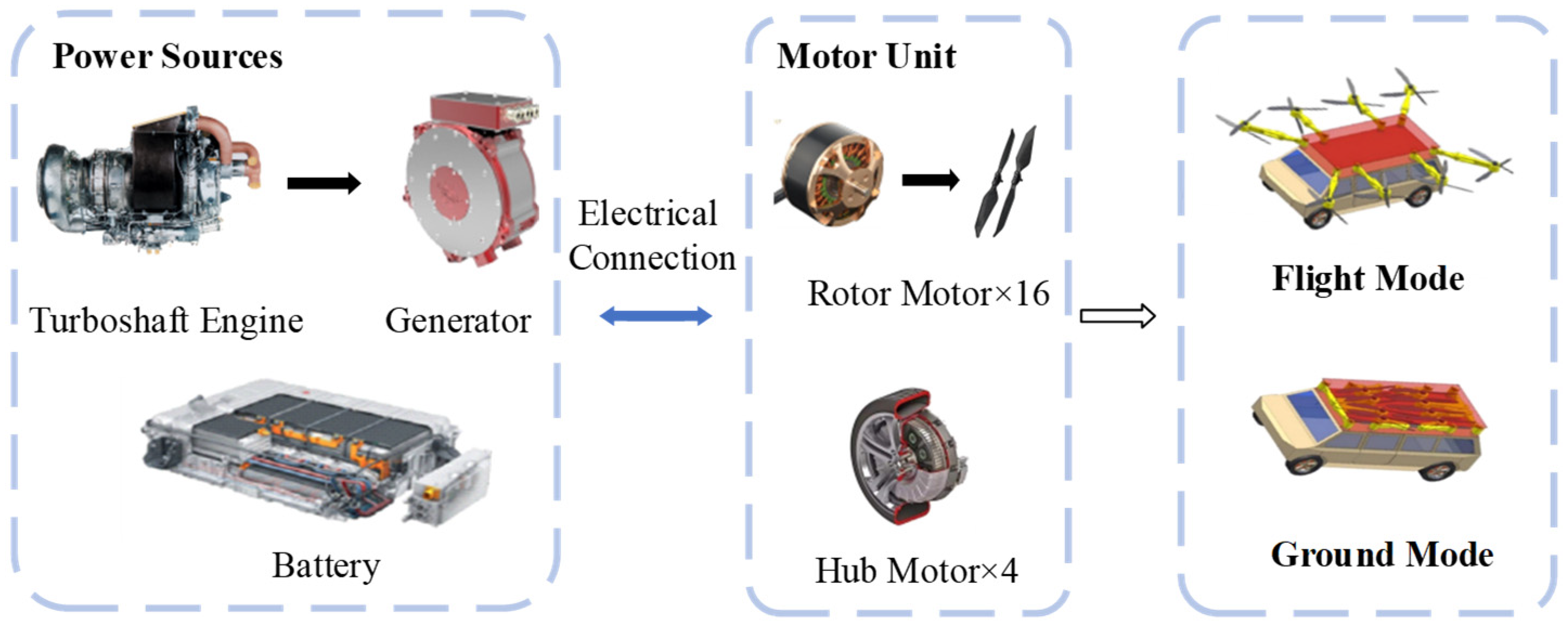
Figure 1. Structure of the studied HEAGV and powertrain system.
Applsci 13 03032 g001
Figure 2. Fuel consumption map of the turboshaft engine.
Applsci 13 03032 g002
Figure 3. Wheel motor efficiency map.
Applsci 13 03032 g003
Figure 4. Rotor motor efficiency map.
Applsci 13 03032 g004
Figure 5. Generation efficiency map.
Applsci 13 03032 g005
Figure 6. The overall control strategy framework.
Applsci 13 03032 g006
Figure 7. SOC reference trajectory.
Applsci 13 03032 g007
Figure 8. Influence of weighting factor κ on battery temperature.
Applsci 13 03032 g008
Figure 9. The HEAGV mission profile in flight and on ground. (a) Driving cycle A. (b) Driving cycle B.
Applsci 13 03032 g009
Figure 10. The HEAGV driving cycles. (a) Driving cycle A. (b) Driving cycle B. The red line represents the speed of the ground; the green line represents the vertical takeoff and landing speed; the blue line represents the speed of the horizontal cruise.
Applsci 13 03032 g010
Figure 11. SOC profiles with different prediction horizon lengths. (a) SOC profiles with different predicted horizon lengths under driving cycle A. (b) SOC profiles with different predicted horizon lengths under driving cycle B.
Applsci 13 03032 g011
Figure 12. Validation of the PMP-MPC strategy under the air-ground driving cycle A. (a) The blue line represents the engine-generator set power; the red line represents the battery power; the green line represents the demand power. (b) Battery temperature profiles. (c) Battery temperature change rate per instant.
Applsci 13 03032 g012aApplsci 13 03032 g012b
Figure 13. Validation of the PMP-MPC strategy under the air-ground driving cycle B. (a) The blue line represents the engine-generator set power; the red line represents the battery power; the green line represents the demand power. (b) Battery temperature profiles. (c) Battery temperature change rate per instant.
Applsci 13 03032 g013
Figure 14. SOC profiles of different approaches. (a) SOC profiles of different approaches in driving cycle A. (b) SOC profiles of different approaches in driving cycle B. (Prediction horizon = 5 s for PMP-MPC).
Applsci 13 03032 g014
Figure 15. Fuel consumption for different methods. (a) Fuel consumption for different methods in driving cycle A. (b) Fuel consumption for different methods in driving cycle B.
Applsci 13 03032 g015aApplsci 13 03032 g015b
Figure 16. Battery temperatures for different methods. (a) Battery temperatures for different methods in driving cycle A. (b) Battery temperatures for different methods in driving cycle B.
Applsci 13 03032 g016
Table 1. Basic HEAGV parameters.
ParameterValueTitle 3
Powertrain systemSeries Hybrid ElectricAir/Ground
Vehicle mass (kg)2000Air/Ground
Gravity acceleration (m/s2)9.81Air/Ground
Wheel radius (m)0.39Ground
Frontal area (m2)7.8Ground
Paddle radius (m)0.9Air
Vertical area while climbing/landing (m2)32Air
Equivalent frontal area in cruise (m2)12.4Air
Engine peak power (kW)110Air/Ground
Rotor-motor peak power (kW)50Air
Hub motor peak power (kW)60Ground
Battery-rated capacity (Ah)150Air/Ground
Battery-rated voltage (V)500Air/Ground
Table 2. Results of PMP-MPC with three prediction horizons in driving cycle A.
Horizon (s)FC (L)Temperature (°C)
578.4729.42
1078.9429.07
1579.6228.74
Table 3. Results of PMP-MPC with three prediction horizons in driving cycle B.
Horizon (s)FC (L)Temperature (°C)
524.7922.12
1025.1222.27
1525.6323.09
Disclaimer/Publisher’s Note: The statements, opinions and data contained in all publications are solely those of the individual author(s) and contributor(s) and not of MDPI and/or the editor(s). MDPI and/or the editor(s) disclaim responsibility for any injury to people or property resulting from any ideas, methods, instructions or products referred to in the content.