Article

Performance Analysis of the Cylinder Gas Film Seal between Dual-Rotor Reverse Shafts Considering Lubrication and Centrifugal Expansion Effects

School of Mechanical Engineering, Northwestern Polytechnical University, Xi’an 710072, China
*
Author to whom correspondence should be addressed.
Appl. Sci. 2023, 13(5), 3076; https://doi.org/10.3390/app13053076
Submission received: 2 February 2023 / Revised: 24 February 2023 / Accepted: 24 February 2023 / Published: 27 February 2023

Abstract

:
The cylinder gas film seal between dual-rotor reverse shafts is a new method for sealing aircraft engines that has excellent developmental prospects. We propose a novel method for determining if the sealing ring is fully fluid-lubricated using the average Reynolds equation. Considering surface roughness and centrifugal expansion, we calculated the dynamic pressure, gas film force and friction power consumption with and without inlet pressure differences for each of the four rotation modes. The gas film’s dynamic pressure effects were weakest when the dual rotors rotated in a reverse direction (Mode 3), with or without differences in inlet pressure, since solid contact is most likely to occur under counter-rotation. When the dual rotors were in counter-rotation with an inlet differential pressure of 80 kPa and fixed inner and outer rotor speeds (e.g., 3000 rpm), we calculated the minimum sealing ring film thickness, leakage rate, friction power consumption and gas film force. Changes in outer rotor speed greatly influenced the minimum film thickness and the sealing ring’s performance. Meanwhile, changes in the inner rotor speed had little influence on the minimum film thickness and sealing ring’s lubrication performance. When the speed difference was fixed and the sealing ring was fully fluid-lubricated, lubrication performance changes were mainly affected by changes in centrifugal expansion caused by the outer rotor speed. Given a fixed rotor speed and under dual-rotor counter-rotation, we calculated the effects of inlet differential pressure changes on minimum gas film thickness, leakage rate, friction power consumption, gas film force and other sealing performance variables. Leakage rate and the friction power consumption increase as inlet differential pressure increases. Our results provide a theoretical reference for avoiding solid contact of the cylinder seal between dual-rotor reverse shafts.

1. Introduction

An aircraft’s engine is the core part of an aircraft and is also an important index for determining a country’s basic industrial prowess [1]; sealing devices are an important engine component, and improvements in sealing performance can improve efficiency, save energy and reduce pollution. Therefore, advanced sealing technologies are necessary to realise future improvements in aircraft performance [2].
An aircraft’s engine requires many parts to establish a tight seal; the oil seal of a bearing chamber is an important sealing system in engine. For example, the bearing chamber oil seal should feature high operational capacity and minimal air leakage to create a strong seal, reduce engine weight and improve performance. To reduce weight and space, the high- and low-pressure rotors in modern engines are usually installed concentrically. In such a case, the intermediate bearing seal between two rotors (also known as the ‘seal between shafts’) should be capable of forming a seal between two moving interfaces. Especially in engines where the two rotors rotate in reverse, the operating environment of the seal between shafts (known as the ‘seal between reverse shafts’) is more hostile. The sealing interface has an extremely high relative sliding speed and small available space, exceeding the operating limits of traditional contact seals. While non-contact labyrinth seals can be used for forming seals between reverse shafts, these seals are prone to leaks and contact wear because their fixed-clearance design cannot adapt to the rotors’ excitation. These factors are likely to affect an engine’s overall performance and have prompted advances in gas film seal technology based on the principle of hydrodynamic and hydrostatic pressure for creating seals between aircraft engine shafts.
In 1983, Eliseo DiRusso of the NASA Lewis Research Center designed a dynamic and static pressure mixed gas film face seal that could slide back and forth in an axial direction [3], leading to the application of the gas film’s seal between engine shafts running in reverse directions. The authors found these seals had leakage rates that were 50–60% of those of the labyrinth seal. However, the test still generated significant friction, and smoking was noted [4]. The reverse gas film face seal has a high risk of contact wear due to axial engine rotor movement. To mitigate this risk, new design schemes have been proposed. Considering this area’s vulnerability to wear and rupture, seals may fail even when a rigid structure’s sealing dam works. Chen Yuan et al. proposed a foil gas film face seal structure with a dynamic pressure floating sealing dam; meanwhile, to improve the dynamic pressure effect, a ring groove was made on the upper-end face of the ring body [5]. Given the fan’s hostile sealing environment, Ying Zhiwei et al. proposed a method for gas film non-contact dual-face mechanical sealing suitable for use with fans [6]. Considering the poor opening performance of the existing foil gas film face seal, Chen Yuan et al. invented a foil gas film face sealing structure with enhanced opening due to circumferential flow and with an airfoil foil as elastic support [7]. To improve the seal’s opening and dynamic pressure effects at high speeds, Peng Xudong et al. invented a gas film face sealing structure with a microporous foil surface [8].
Since the face seal cannot adapt to high axial excitation, some scholars proposed the cylinder gas film seal technology to form seals between reverse shafts. For instance, Hou et al. [9] proposed a flexible cylinder sealing structure with metal rubber and calculated the effects of rotor tilt, centrifugal expansion and other factors under stable conditions on the gas film’s pressure distribution using a numerical computational method. Rotor tilt and centrifugal expansion had major effects on the gas film’s pressure distribution. Hou et al. [10] proposed an aeroelastic coupling method by calculating the floating ring’s opening force and the effects of rotor rotation direction, sealing ring width, rotor speed, rotor radius and other factors. Hou et al. [11], on the basis of the aeroelastic coupling method and considering the influence of centrifugal expansion, investigated eccentricity and inner/outer rotor speed on sealing performance. Unfortunately, the effects of surface roughness and temperature were not considered.
On the whole, few reports of gas film seals between shafts exist. Most face or cylinder gas film seals being studied have problems sealing the rotor and stator interfaces and are generally used in ground machinery under relatively stable conditions. Analysing gas film performance is important for improving the seals that exist between reverse shafts, such as for cylinder gas film seals. Beermann et al. [12,13] proposed a radial adaptive sealing device for cylinder gas film seals and calculated the effects of different gas film gaps and inlet pressure on the gas film’s pressure characteristics using the CFD method. Sun et al. [14] proposed a flexible support sealing method and studied the effects of various sealing rings and structural parameters of the T-groove on the sealing performance under stable conditions. Their analysis used computer simulations and the fluid-structure coupling analysis method to reveal gas film thickness, eccentricity and other factors that could affect sealing performance. Sun et al. [15] examined rotor speed, different inlet pressure and gas viscosity effects on gas film stiffness, leakage and T-groove cylinder seal force using the CFD method. Li et al. [16] examined T-groove cylinder gas film seal groove parameters on sealing performance and concluded that groove depth principally affected the gas seal’s performance using orthogonal testing procedures. Yu et al. [17] found that the spiral groove model demonstrates better dynamic pressure effects under identical conditions by calculating and comparing eccentricity, speed and differential pressure effects on the sealing performance with and without a spiral groove. Dai et al. [18] calculated and analysed the effects of seal gap, speed, viscosity and differential pressure on the sealing performance using the CFD numerical analysis method.
Most current studies on gas film seals have used numerical calculations or CFD analysis. However, different from the existing seals at the rotor and stator interface, the cylinder gas film seal between reverse shafts studied herein is used between two rotors rotating at high speeds simultaneously, proving that the effect of the direction and size of the sealing interface on the flow and bearing capacity of sealing fluid is an important basic work for the design of seals. Furthermore, when dealing with micron-thick gas films, the roughness of the sealing interface cannot be ignored when vibration causes radial runout in engine rotors. We propose a cylinder gas film sealing structure. First, we established a force balance sealing ring analysis model considering the centrifugal expansion effects of sealing at high speeds. We determined the degree of solid contact between the sealing ring and the inner rotor using the minimum gas film thickness. Finally, we calculated the sealing ring’s performance parameters using the average Reynolds equation and the micro-convex contact theory.

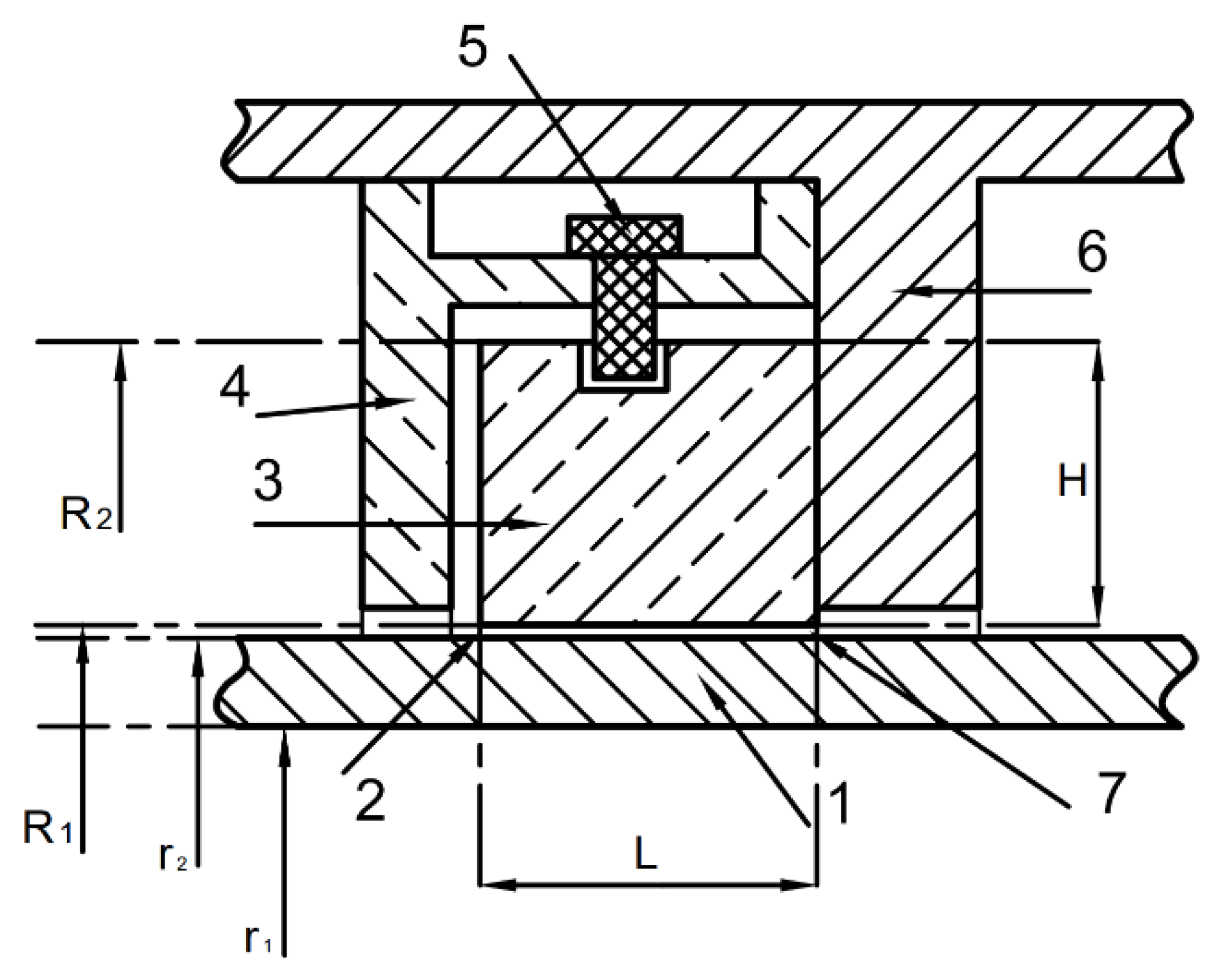
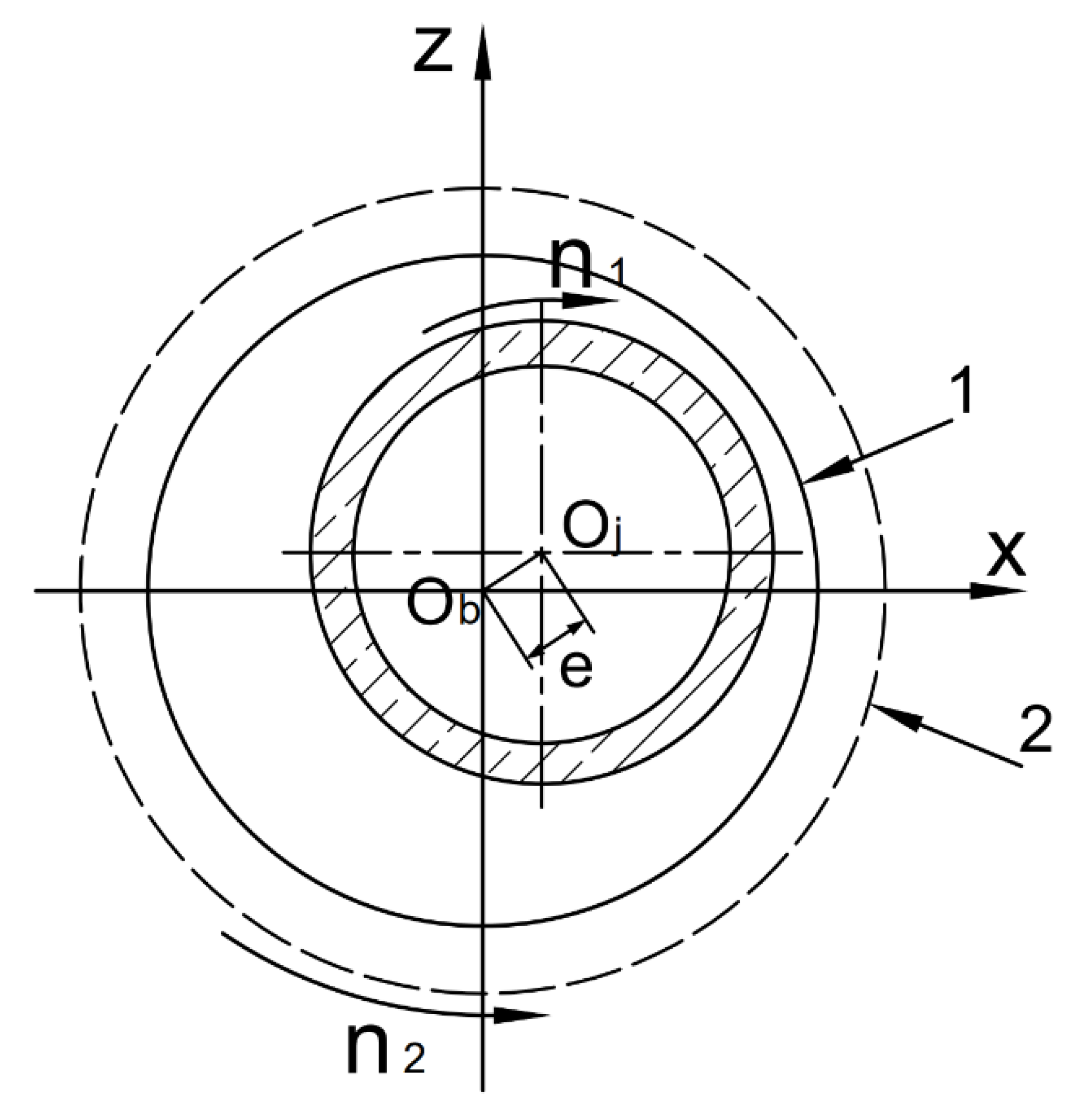
2. Geometry of Cylinder Gas Film Seal between Shafts

Figure 1 depicts the cylinder gas film seal between shafts. The sealing ring is located between concentrically mounted inner and outer rotors. The ring is connected with the outer rotor by an anti-rotating pin and rotates with the outer rotor. Under the action of high-pressure chamber gas, one end of the sealing ring contacts the outer rotor to prevent radial leakage. To adapt to the adverse conditions of high-speed rotation and axial rotor movement, we designed an interface that matches the inner diameter of the seal ring and the outer diameter of the inner rotor with a certain initial clearance to form a wedge during installation. As the rotors and sealing ring rotate, the sealing ring is floated as a result of fluid dynamic pressure action formed in the wedge space, eventually reaching a state of no contact. Therefore, the main seal leak is formed by the radial clearance between the sealing ring and the inner rotor.
The geometric parameters and operating conditions of the cylinder gas film seal between shafts are included in Table 1.

3. Force Balance Conditions

Since the sealing ring rotates with the outer rotor, its sealing performance mainly depends on the relative positions of the sealing ring and inner rotor. Figure 2a shows this relationship under a state of force balance. The force conditions of the sealing ring in such cases are shown in Figure 2b. In the axial direction, the sealing ring is subjected to the force generated by the inlet fluid pressure F 1 and the force exerted on it by the outer rotor F 4 , which satisfies the following:
F 1 + F 4 = 0
In the radial direction, the sealing ring is subjected to the force exerted by inlet fluid pressure F 3 , the gravity of the sealing ring F G , bearing capacity of the gas film F g , side friction F f and centrifugal force F 2 , and reaches balance as follows:
F G + F 2 + F 3 + F f + F g = 0
The magnitude of each force in Formula (2) is as follows:
F G = ρ 2 π ( R 2 2 R 1 2 ) L g
F 2 = m ω 2 2 e = ρ 2 π ( R 2 2 R 1 2 ) L ω 2 2 e
F 3 = 2 π R 2 L P i n
F f = μ F 4 μ P i n s
where ρ 2 is the density of the sealing ring material, m is the mass of the sealing ring, e is the eccentric distance of the sealing ring, ω 2 is the angular velocity of the sealing ring, μ is the friction coefficient between the sealing ring and the outer rotor, p i n is the inlet pressure and s is the contact area between the right end face of the sealing ring and the outer rotor. The bearing capacity of the gas film F g is obtained by flow field lubrication analysis (to be detailed in the next section).

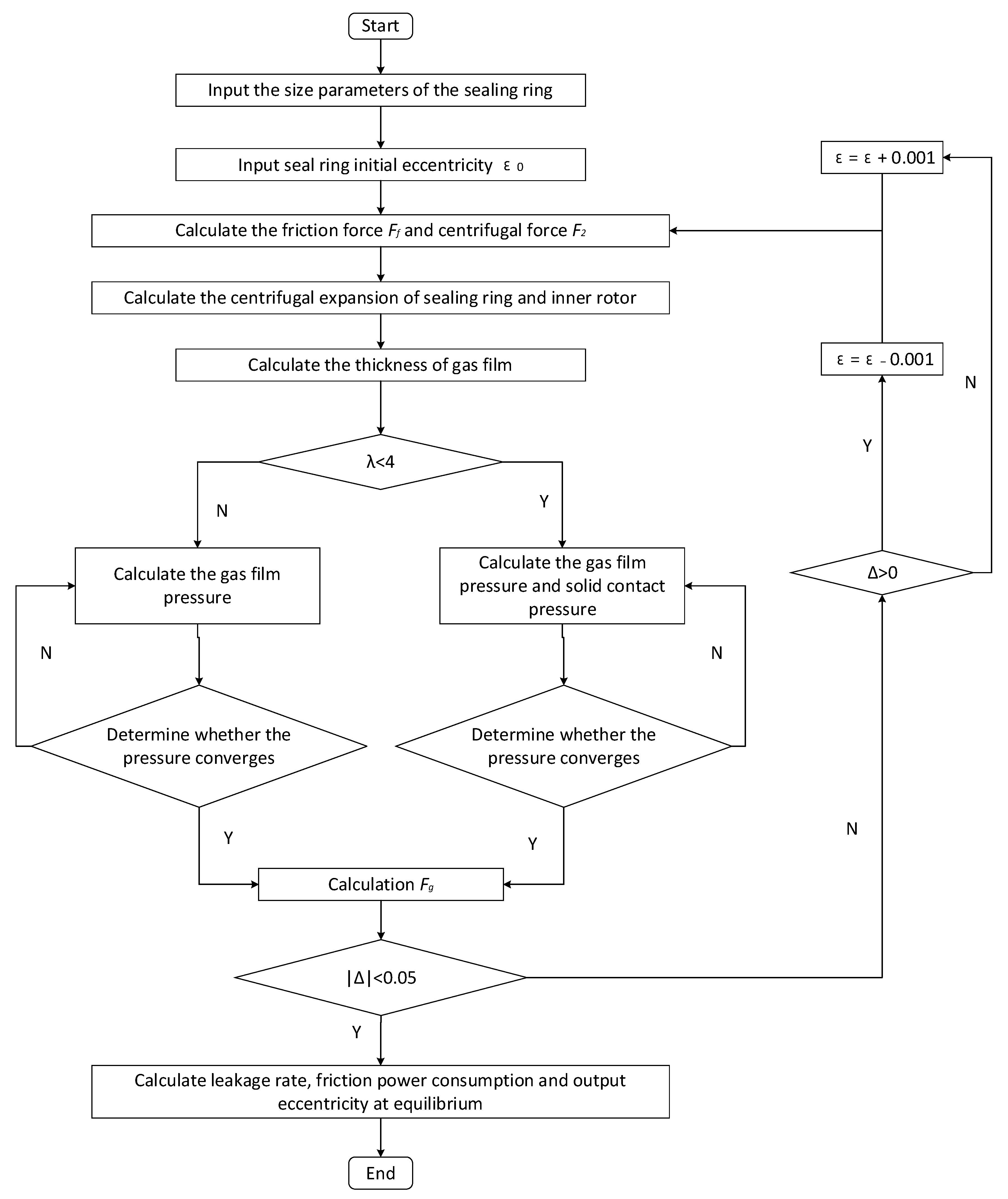
4. Numerical Computational Method for Sealing Performance

Determining the morphology of the gas film gap between the sealing ring and the inner rotor is key to determining the seal’s potential leak and tribological characteristics. The centrifugal expansion effect of the rotor and the sealing ring on the gas film gap should be considered for rotors and sealing rings rotating at high speeds. The seal’s gas film force can be determined using a dynamic lubrication analysis of the flow field according to sealing conditions. Since the gas film force is related to the eccentric position of the sealing ring, we first define the sealing ring’s structural conditions and set the initial eccentricity. Next, we calculate friction, centrifugal force, centrifugal expansion and minimum gas film thickness. The lubrication condition is determined according to the film thickness ratio λ [19]. If λ exceeds 4, the gas film force is calculated by full fluid lubrication condition. If λ is smaller than 4, the gas film force is calculated by the fixed friction state considering the contact force generated by rough surface-to-surface contact. The gas film pressure in calculating gas film force will satisfy the convergence condition, as shown in Formula (7). The friction, centrifugal force, gas film force and other calculation results from the above calculation are substituted into Formula (2) to determine if the force equilibrium condition is satisfied. If not, the eccentricity of the sealing ring should be corrected until the convergence condition is reached, as shown in Formula (8). The calculation is shown in Figure 3.
δ = j = 1 n i = 1 m | P i , j ( k ) P i , j ( k 1 ) | j = 1 n i = 1 m | P i , j ( k ) | 1 × 10 5
| Δ | = | F G + F 2 + F 3 + F f + F g | 0.05

4.1. Method for Calculating the Bearing Capacity of Gas Film

4.1.1. Gas Film Thickness

The film thickness equation for the seal between shafts is as follows [10]:
h = C ( 1 + ε cos θ )
where C is the gap between the sealing ring and the inner rotor radius, and ε is eccentricity, which changes with the pressure in the fluid (as shown in Figure 3). We must consider the centrifugal expansion effect of the rotor and the sealing ring. Since the sealing ring rotates with the outer rotor, we only considered the centrifugal expansion effects of the sealing ring and inner rotor radius C . The gap between the sealing ring and the inner rotor radius C is as follows [9]:
C = R 1 + u s ( R 1 ) r 2 u r ( r 2 )
where u s and u r are the centrifugal elastic deformation of the sealing ring and the inner rotor, and can be calculated using the elastic mechanics method [9].
u s ( R 1 ) = ( 1 ν 2 2 ) ρ 2 n 2 2 R 1 3 8 E 2 + [ p ( 1 ν 2 ) R 2 2 E 2 ( R 2 2 R 1 2 ) + ( 1 ν 2 ) ( 3 + ν 2 ) ρ 2 n 2 2 ( R 2 2 + R 1 2 ) 8 E 2 ] R 1 + [ p ( 1 + ν 2 ) R 2 2 R 1 2 E 2 ( R 2 2 R 1 2 ) + ( 1 + ν 2 ) ( 3 + ν 2 ) ρ 2 n 2 2 R 2 2 R 1 2 8 E 2 ] 1 R 1
u r ( r 2 ) = ( 1 + v 1 ) ( 3 2 v 1 ) 8 E 1 ( 1 v 1 ) ρ 1 n 1 2 r 2 [ ( 1 2 v 1 ) ( r 1 2 + r 2 2 ) + r 1 2 r 2 2 r 2 ] ( 1 + v 1 ) ( 1 2 v 1 ) 8 E 1 ( 1 v 1 ) ρ 1 n 1 2 r 2 3
where E 1 is the elasticity modulus of the inner rotor, E 2 is the elasticity modulus of the sealing ring, ν 1 is the Poisson’s ratio of the inner rotor, ν 2 is the Poisson’s ratio of the sealing ring, ρ 1 is the density of the inner rotor and ρ 2 is the density of the sealing ring.
Generally, the sealing ring is made of graphite. The centrifugal expansion effect on the seal gap at high speeds cannot be ignored. Performance parameters for the inner rotor and sealing ring in the sealing structure are listed in Table 2 [20].

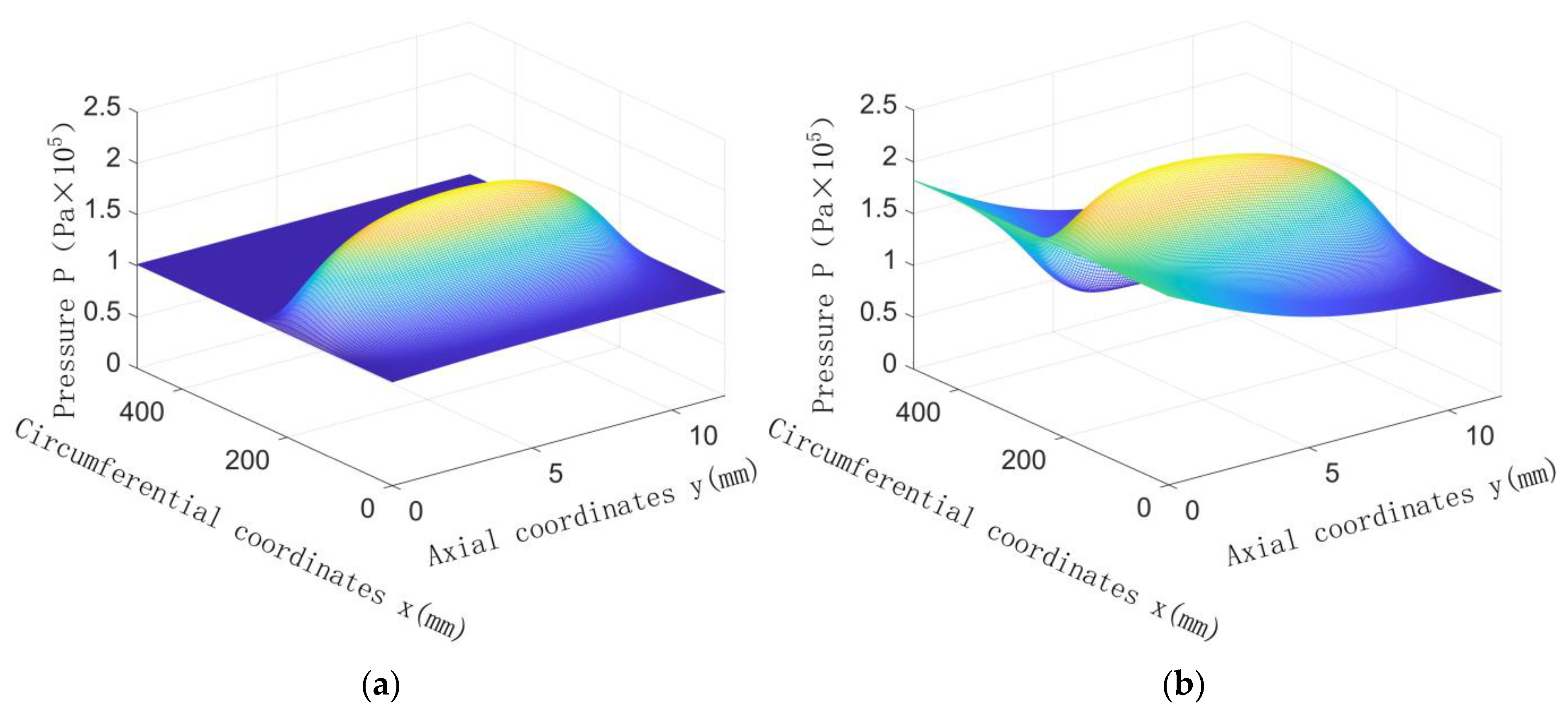
4.1.2. Gas Film Force

The dynamic pressure gas film force calculated using the gas lubrication equation can be solved using the average Reynolds equation [21] in an isothermal state, as shown in Formula (14). Meanwhile, the following assumptions should be satisfied [22]:
  • The fluid in the gap is fully developed laminar flow;
  • The fluid is viscous and conforms to Newton’s law of viscosity;
  • The gas film thickness is very small compared with other geometric sizes, and the ratio is generally less than 10−4;
  • The fluid is an isothermal ideal gas and
  • The fluid satisfies the no-slip boundary condition at the gas-solid boundary.
Considering an isothermal ideal gas, the state equation for the gas is given by Formula (13):
p ρ 3 = g T
x ( ϕ x h 3 12 η p ¯ x ) + y ( ϕ y h 3 12 η p ¯ y ) = ( n 1 r 2 + n 2 R 1 ) 2 h ¯ T x + ( n 1 r 2 n 2 R 1 ) 2 σ ϕ s x + h ¯ T t
In Equation (14):
ϕ x = 1 C 0 e r ( h σ ) , γ 1 ,   ϕ x = 1 + C 0 ( h σ ) r , γ > 1 ,   ϕ y ( h σ , γ ) = ϕ x ( h σ , 1 γ )
γ = l θ l y , l θ is the circumferential direction of the sealing ring; l y is the width direction of the sealing ring.
ϕ s = ( 2 V 1 1 ) Φ S
In Equation (15):
  • Φ s = A 1 ( h σ ) α 1 e α 2 h σ + α 3 ( h σ ) 2 , h σ 5 ,
  • Φ s = A 2 e 0.25 h σ , h σ > 5 ,
  • V 1 = ( σ 1 σ ) 2 ,
  • σ = σ 1 2 + σ 2 2 ,
where ρ 3 is gas density; C 0 , r are constant, respectively (available in reference [21]); σ 1 is the root mean square value of the inner rotor surface roughness; σ 2 is the root mean square value of the sealing ring roughness; σ is the comprehensive surface roughness (the value in this paper is 0.8); p is gas pressure; g is the gravitational acceleration; T is the absolute temperature; ϕ x and ϕ y are the pressure flow coefficient; ϕ s is the shear flow coefficient; p ¯ is the mean fluid pressure and h ¯ T is the average film thickness. Let the resultant force in the eccentric direction of the centre of the rotor and the centre of the floating sealing ring be W n ; the resultant force in the vertical eccentric direction is W t , and the value is as follows [23]:
{ W n = 0 L 0 2 π ( p p a ) r 2 cos θ d θ d y W t = 0 L 0 2 π ( p p a ) r 2 sin θ d θ d y
The dynamic pressure of the gas film is as follows:
F p = p a r 2 2 W n 2 + W t 2

4.1.3. Conservation of Momentum [24]

The momentum conservation equation is also a basic law that any flow system must meet. The law can be expressed as follows: the rate of change of the momentum of the fluid in the micro-element with respect to time is equal to the sum of various forces acting on the micro-element. According to this law, the momentum conservation equation in the x , y , z directions can be derived:
( ρ 3 u x ) t + ( ρ 3 u x u ) = p x + τ x x x + τ y x y + τ z x z + ρ 3 f x
( ρ 3 u y ) t + ( ρ 3 u y u ) = p y + τ x y x + τ y y y + τ z y z + ρ 3 f y
( ρ 3 u z ) t + ( ρ 3 u z u ) = p z + τ x z x + τ y z y + τ z z z + ρ 3 f z
where τ x x , τ y y , τ z z , τ y x , τ z x and τ y z are the component of viscous stress τ acting on the surface of the micro-element due to molecular viscosity. f x , f y and f z are the unit mass force in the x , y and z directions. u x , u y and u z are the velocity components in the x , y and z directions.

4.1.4. Bearing Capacity of the Gas Film under Mixed Lubrication Conditions [25]

When the film thickness ratio of the gas film is smaller than 4, and the seal is in a mixed lubrication state, the pressure from the contact between the sealing ring and the rough peak of the inner rotor is as follows:
A = n π R σ
F o = 4 E * A 3 2 3 π 1 2 N 1 2 R
In such cases, the bearing capacity of the gas film is as follows:
F g = F o + F p
where F p is the dynamic pressure gas film force, F o is the total contact force of the rough peak under mixed lubrication condition, E * is the comprehensive elasticity modulus, R is the ideal radius of the rough peak (the value in this paper is 1.2 μm) and A is the total contact area of the rough peak.

4.2. Sealing Performance Indexes

4.2.1. Calculating Gas Leakage Rate [10]

Mass leakage rate:
Q = 0 2 π p T ( h 3 12 η p y ) r 2 d θ
where Q is the mass leakage rate, p is the gas pressure and y is the axial coordinate of the sealing ring.

4.2.2. Calculation of Friction Power Consumption [23]

Although the cylinder gas film seal between reverse shafts is a non-contact seal, we cannot ignore the friction power consumption generated due to the sealing surface’s high-speed rotation, the small sealing gap and the high viscous shear forces inside the sealing gas. Factors that can affect gas friction power consumption are the sealing gap, the gas’s viscosity and sealing surface speed. The formula for calculating friction power consumption is as follows:
W = M ω R 1 r 2
where ω is the relative speed of gas and M is the friction moment. The formula for calculating the friction moment is as follows:
p o = 4 E * 3 R 1 2 σ 3 2
M = 0 L 0 2 π ( p s r 2 θ h 2 + η ω r 2 h ) r 2 2 d θ d y
When λ < 4 , p s = p + p o ;
When λ > 4 , p s = p .
p o is the contact pressure of the rough peak when the film thickness ratio is smaller than 4, and the seal is considered to demonstrate a mixed lubrication state; the friction power consumption also includes the effects of friction caused by rough contact.

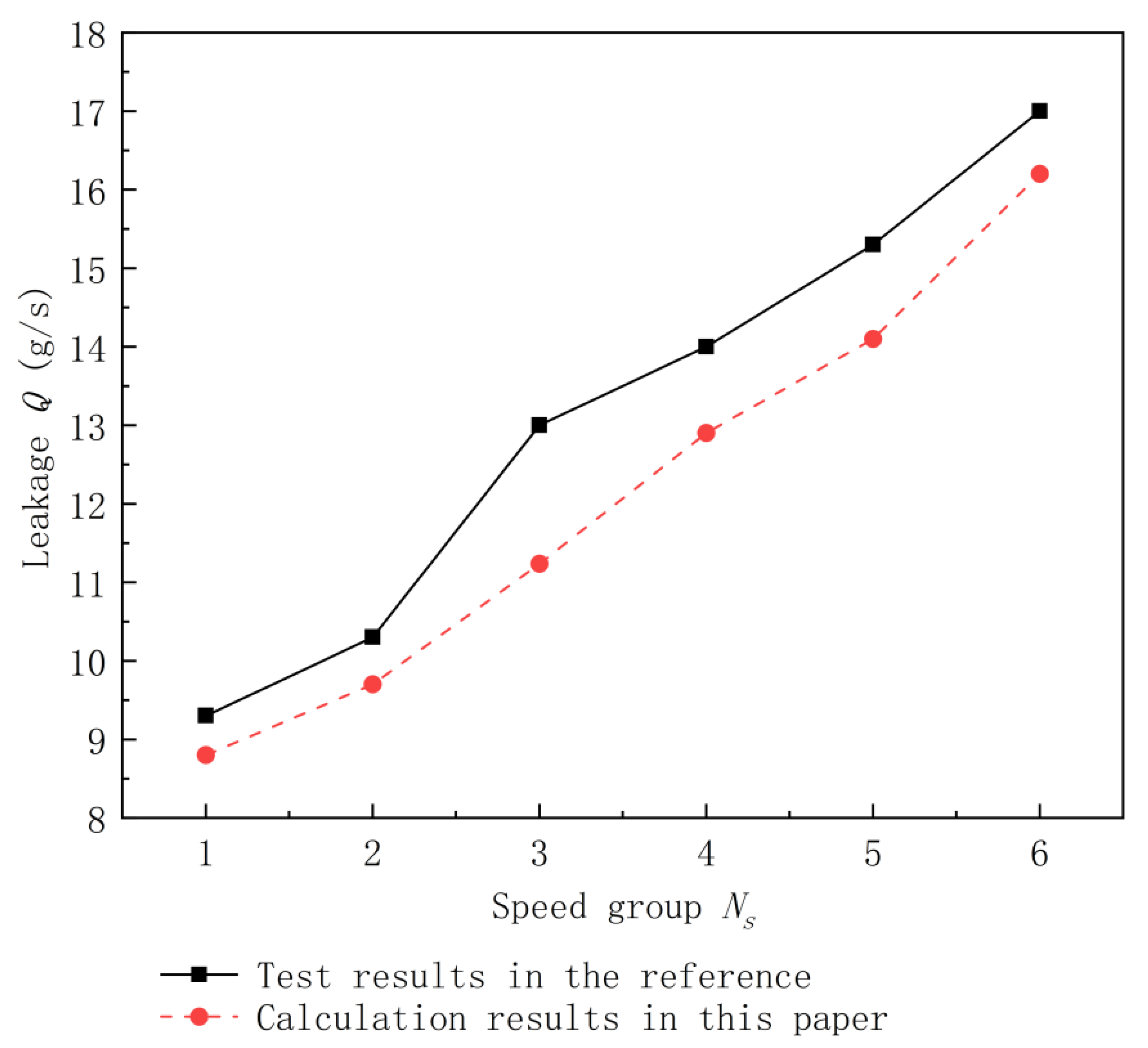
4.3. Verification of Analysis Method

To verify the model’s accuracy, we calculated the sealing ring’s leakage rates at six different speeds and compared them with the results in literature [21]. As shown in Figure 4, the changes in the calculated results were consistent with the test results. The maximum error was 15.15%, indicating the calculation model is correct. The speeds of the inner and outer rotors corresponding to the six speed groups are shown in Table 3.

5. Results and Discussion

5.1. Effects of Dual-Rotor Rotation Direction on Sealing Performance

The seal between shafts is special because it couples two rotating rotors. To study the effects of rotational direction on the hydrodynamic lubrication of the sealing gap, we analysed the sealing performance of inner and outer rotors rotating in the same direction, inner and outer rotors rotating in counter-rotation and the inner and outer rotors rotating uniaxially. Our results were compared with the four modes listed in Table 4 as examples.
Figure 5, Figure 6, Figure 7 and Figure 8 show the gas film’s pressure distribution cloud map with and without sealing differential pressure in the four rotation modes. Figure 9 compares the gas film’s force and friction power consumption with and without sealing differential pressure in the four rotation modes. Considering only the effects of the rotation direction on the fluid dynamic pressure effect, we found that when two rotors rotated in the same direction (as shown in Figure 5), there were large pressure peaks in the circumferential and axial directions; the gas film’s dynamic pressure effect was best in this condition. However, during counter-rotation (as shown in Figure 7), the dynamic pressure effect of the gas film was the weakest. The gas film’s dynamic pressure effects on the dual-rotor movement’s static state (as shown in Figure 6 and Figure 8) exist between these two extremes. According to the hydrodynamic pressure principle, the fluid film’s pressure distribution relates to fluid viscosity, the sliding velocity of two moving surfaces, fluid film thickness and variations on these factors. If fluid viscosity and film thickness are unchanged, fluid will enter from the large opening of the wedge space and flow out of the small opening when the rotors move in the same direction. These activities enhance the hydrodynamic pressure effect. Thus, the maximum pressure of the gas film is greater than that when only one wall is moving. On the other hand, during counter-rotation, the hydrodynamic pressure effect was weakened to less than that observed when only one wall was moving.
As shown in Figure 5, Figure 6, Figure 7 and Figure 8, when there is inlet/outlet differential pressure, Δ P = 80 kPa. The gas film’s dynamic pressure effects were best when the two rotors rotated in the same direction (as in Figure 5). The gas film’s dynamic pressure effects were weakest under counter-rotation (as in Figure 7). Compared with the mode without differential pressure, the gas film’s maximum pressure distribution shifted towards the inlet (position 0 of the L coordinate) because of increased inlet pressure. Additionally, the maximum pressure increased. When the rotors ran in the same direction, the gas film’s maximum pressure value, without differential pressure, was 0.2143 MPa. Meanwhile, the gas film’s maximum pressure value, without differential pressure, was 0.2331 MPa. Under counter-rotation, the gas film’s maximum pressure value (without differential pressure) was 0.1296 MPa. Meanwhile, the gas film’s maximum pressure, with differential pressure, was 0.18 MPa. The gas film pressure results from hydrostatic pressure and the rotary dynamic pressure effect; these combine to form the between-shaft seal. Therefore, the presence of a pressure differential increases gas film pressure and improves the gas film’s force. These effects are evident from the sealing gas film force results under the four rotation modes (Figure 9). Although the bearing capacity of the gas film is maximised when the two rotors rotate in the same direction biaxially and minimised when the two rotors are in counter-rotation biaxially with/without differential pressure, gas film forces varied during each rotation mode, with significantly reduced differential pressure. Compared with Mode 1 (Figure 5), the gas film force in Mode 3 (Figure 7) was reduced by about 48.67% without differential pressure and 25.86% with differential pressure. Thus, inlet differential pressure mitigates the adverse dynamic pressure effects of the inversion interface and improves the gas film’s bearing capacity.
As shown in Figure 9, friction power consumption is maximised when the two rotors rotate in the same direction biaxially with/without differential pressure. Meanwhile, friction power consumption is minimised during counter-rotation. Measures of the friction power consumption when the two rotors rotate uniaxially exist between these two extremes since friction power consumption is mainly associated with fluid velocity in the gas film gap. The fluid velocity is maximised during same-direction rotation and minimised during counter-rotation. As can be seen from the comparison of the friction power consumption with/without differential pressure in different rotation modes, there are fewer changes in friction power consumption at different pressures. For instance, compared with Mode 1 (Figure 5), the friction power consumption without differential pressure in Mode 3 (Figure 7) decreases by about 32.14%; meanwhile, the friction power consumption with differential pressure decreases by about 25.78%.
During counter-rotation, the gas film’s dynamic pressure effects are weak, the bearing capacity is small, and contact wear is likely between the rotor and the sealing ring. Thus, sealing shafts in counter-rotation was a challenge for analysis and design. Therefore, the following will focus on the sealing performance when the inner and outer rotors rotate in reverse.

5.2. Effects of Rotor Speed on Sealing Performance

When the inner and outer rotors are in counter-rotation, we discuss the sealing performance under three conditions: (1) where only the inner rotor speed changes, (2) where only the outer rotor speed changes and (3) where the speed of both the inner and outer rotors changes synchronously (with unchanged absolute speed difference).

5.2.1. Changes in Inner Rotor Speed

Figure 10 shows the effects on leakage rate and friction power consumption during counter-rotation of the inner and outer rotors when the inlet differential pressure is 80 kPa and the outer rotor speed is 7000 rpm. For clarity, this figure depicts only the minimum film thickness at different inner rotor speeds. Seal leaks decrease as the inner rotor’s speed increases, secondary to enhancements of the gas film’s dynamic pressure. Although the inner rotor’s centrifugal expansion increases with increasing speed, its elasticity modulus is great. Consequently, the centrifugal expansion is much less than the observed increases in film thickness due to the dynamic pressure effect. As the inner rotor’s speed increases, the minimum film thickness increases and the leakage rate decreases. In addition, the friction power consumption of the seal decreases significantly and then increases slightly with increasing inner rotor speed.
When the inner rotor speed is less than 8788 rpm, the corresponding minimum gas film thickness will be smaller than the critical film thickness (3.2 μm) in the mixed mixture state. Here, significantly more friction power is consumed due to the contact with the rough peak than is consumed during the full fluid lubrication condition. Secondly, when the inner rotor speed increases to 11,000 rpm, the gas film’s dynamic pressure effect increases, and the minimum film thickness significantly decreases. As a result, the friction power consumption further decreases. When the inner rotor speed exceeds 11,000 rpm, the minimum gas film thickness tends to have a gradual change. However, as the inner rotor’s speed increases, the gas film’s relative speed will also increase. Moreover, the gas film’s dynamic pressure effect increases frictional resistance. Consequently, friction power consumption increases slightly when the film is fully lubricated.

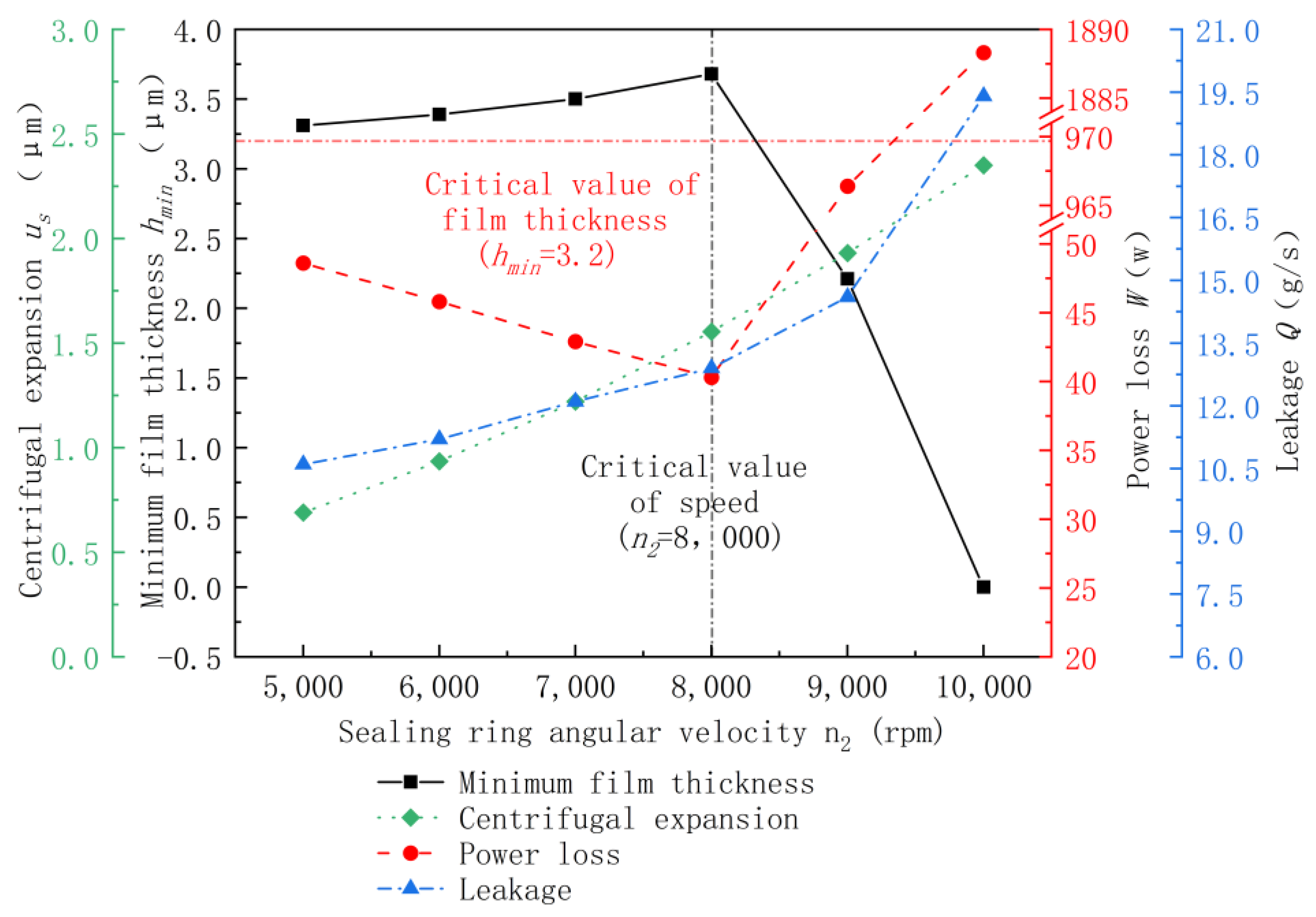
5.2.2. Changes in Outer Rotor Speed

Figure 11 shows the effects of the changes to the counter-rotation speed of the outer rotor within 5000~10,000 rpm when the inlet differential pressure is 80 kPa and the inner rotor speed is 10,000 rpm on the seal’s leakage rate and friction power consumption. For easy analysis, changes in the minimum film thickness and eccentricity are included in Figure 11. Since the two rotors are in counter-rotation with a stable inner rotor speed of 10,000 rpm, as the outer rotor’s speed increases, the relative movement speed of the gas film decreases, and the effects of dynamic pressure on the gas lubrication state gradually weaken. When the speed of the inner and outer rotors is 10,000 rpm, the minimum film thickness approaches zero, indicating maximum leak and friction power consumption.
As outer rotor speed increases, the leakage rate of the seal increases because, with the relative speed of the gas film decreasing, the gas film’s dynamic pressure effect and resistance to axial movement weaken. The minimum film thickness increases then decreases before the outer rotor speed increases to 8000 rpm (the critical speed); the relative movement speed of the gas film is sufficiently high, and the gas film’s dynamic pressure is sufficient to support the sealing ring for full fluid lubrication. Although the increase in the outer rotor’s speed weakens, the dynamic pressure effect, the speed and the centrifugal expansion of the sealing ring also increase. Therefore, the minimum film thickness increases slightly (Refer to the schematic diagram for the effects of the centrifugal expansion of the sealing ring on the minimum film thickness shown in Figure 12. Position 1 is the initial position of the sealing ring when there is no speed. Position 2 is the position of the sealing ring with speed.) Once the outer rotor speed reaches the critical speed of 8000 rpm, the relative movement speed of the gas film decreases, and the dynamic pressure effect weakens with further increases in sealing ring speed (despite increases in the sealing ring’s centrifugal expansion) and the minimum film thickness decreases. The friction power consumption increases first and then increases since, before the outer rotor speed reaches the critical speed (about 8000 rpm), the dynamic pressure effect of the gas film is sufficient. The sealing ring and the inner rotor are fully fluid-lubricated (the minimum film thickness exceeds the critical value). The friction power consumption is mainly related to the gas film’s relative speed. As the outer rotor speed increases, the relative speed of the gas film decreases, and friction power consumption decreases slightly. When the outer rotor speed exceeds the critical speed, the minimum gas film thickness is smaller than the critical value of film thickness. The sealing ring and the inner rotor are in a mixed lubrication state, and solid contact occurs. As the outer rotor speed increases, the minimum film thickness further decreases, mixed lubrication becomes more obvious, and friction power consumption increases significantly.

5.2.3. Synchronous Changes in the Speed of Inner and Outer Rotors

The speed of inner and outer rotors in engines often changes synchronously. The combined mode of the speed of inner and outer rotors shown in Table 5 presents the effects of the synchronous changes in inner and outer rotor speed on sealing performance, with an absolute speed difference between the two rotors (3000 rpm) unchanged. The results are shown in Figure 13.
Our formulas indicate that the gas film seal’s minimum thickness exceeds the critical value under each corresponding speed condition (i.e., it is in a state of full fluid lubrication). When the inner and outer rotor speeds increase synchronously, the difference in speed between the inner and outer rotors and the dynamic pressure effects remains unchanged. However, increases in the absolute speed also increase the centrifugal expansion of the graphite sealing ring with a small elasticity modulus, slightly increasing the minimum film thickness. This exacerbates leaks and decreases friction power consumption.

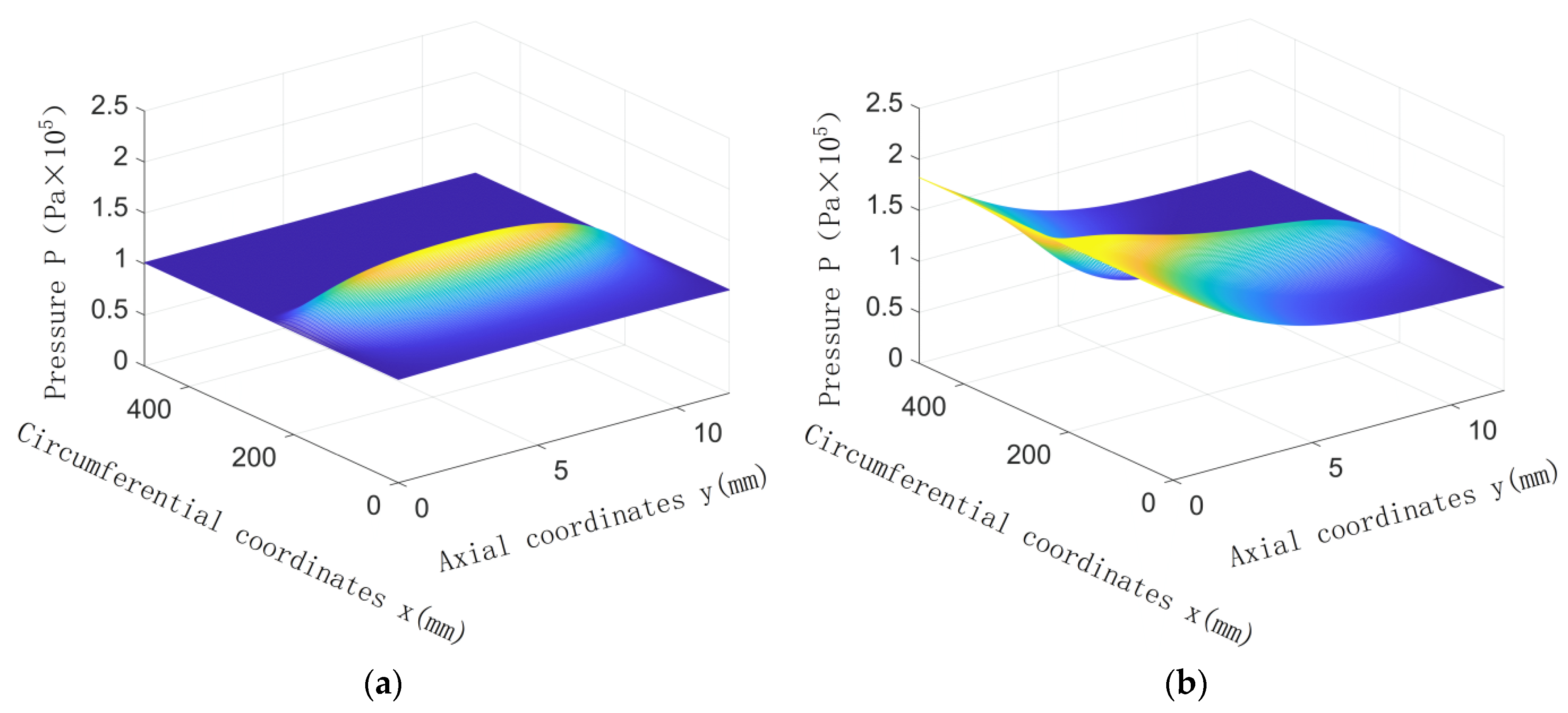
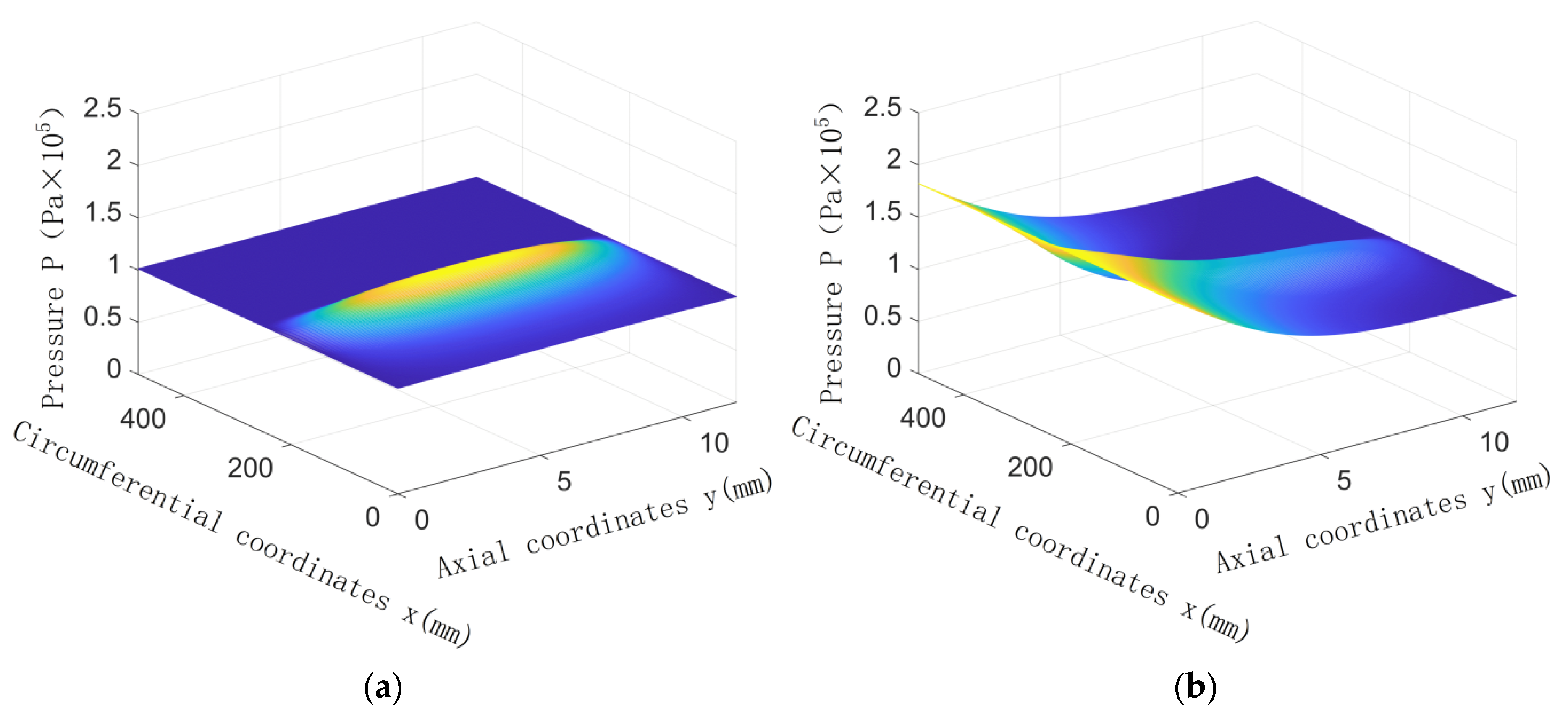
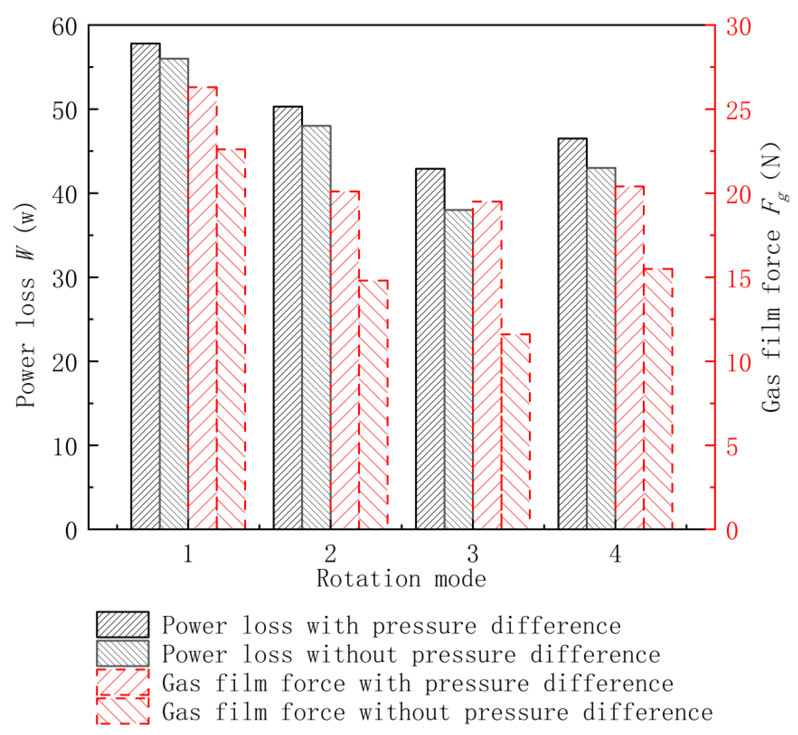
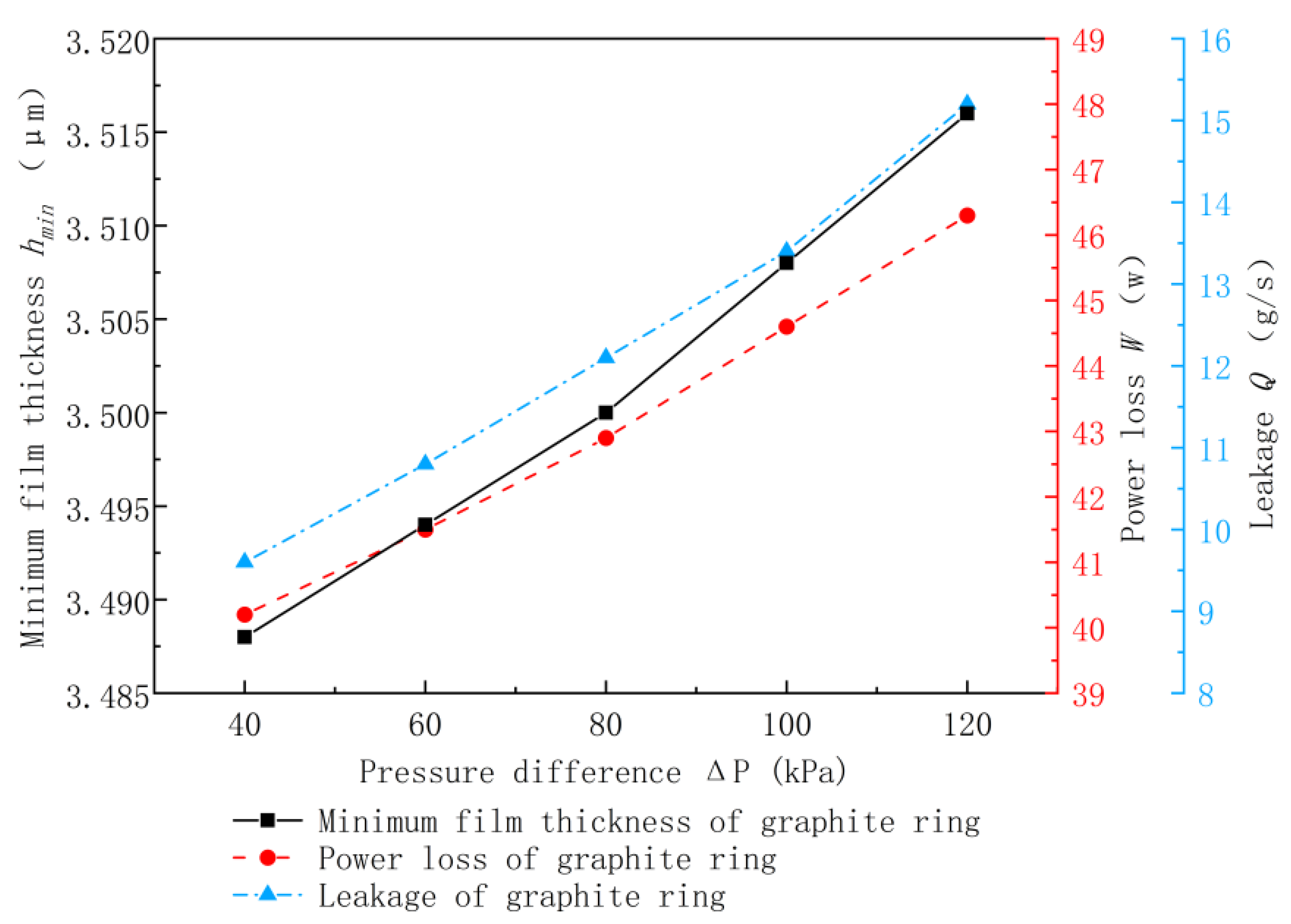
5.3. Differential Pressure Effects on Sealing Performance

Figure 14 shows the effect of the changes in differential pressure on sealing performance when the inner rotor speed is −10,000 rpm and the outer rotor speed is 7000 rpm. As differential pressure increases, the minimum film thickness increases slightly while the leakage rate and friction power consumption increase significantly. The increase in differential pressure increases the gas pressure flow velocity, thus increasing the leakage rate and friction power consumption. At this speed, the dynamic pressure effect of the gas film is sufficiently strong, and the sealing ring is fully fluid-lubricated. As differential pressure increases, the gas’s film force increases, and the eccentricity decreases slightly, causing the minimum gas film thickness to increase accordingly. Under the dynamic pressure effect of the same strength, as differential pressure increases, the axial speed and the leakage rate also increase. When differential pressure increases, a similar increase is observed in the gas film’s overall pressure. During full fluid lubrication, friction power consumption increases.

6. Conclusions

  • When the inner and outer rotors rotate in the same direction, the fluid’s dynamic pressure effect on the gas film gap is the most significant, and the gas film forces are maximised. When the inner and outer rotors are in counter-rotation, the dynamic pressure effect is the weakest, and the gas film force is minimised. When only one rotor rotates, the gas film force generated will be between the two aforementioned extremes. The inlet differential pressure weakens the adverse dynamic pressure effects at the counter-rotation interface and improves the gas film’s bearing capacity to some extent. When the differential pressure is 80 kPa and under the calculation condition herein, the gas film force increases by about 68.1% more than without differential pressure when the inner and outer rotors are in counter-rotation. When the inner and outer rotors rotate in the same direction, the gas film force increases by about 16.37% more than without differential pressure. When rotating in the same direction, the gas film force is 34.87% greater, and the friction power consumption is 34.73% greater than when the two rotors are in counter-rotation.
  • For the seal between counter-rotating shafts, when the outer rotor speed is fixed but the inner rotor speed increases, the seal’s leakage rate and friction power consumption decrease. Before the minimum film thickness reaches the critical film thickness, contact with the rough peak increases friction power consumption significantly. When the inner rotor speed is fixed but the outer rotor speed increases, the centrifugal expansion and the leakage rate of the sealing ring increase, but the friction power consumption decreases first and then increases. When the absolute difference in the speed of the inner and outer rotors is fixed, and the inner and outer rotors are synchronously accelerated, the leakage increases due to the increase in the centrifugal expansion of the sealing ring; however, the friction power consumption decreases.
  • For the seal between counter-rotating shafts, when the sealing differential pressure increases, the seal’s leakage rate and friction power consumption increase significantly.

Author Contributions

Conceptualization, S.Z. and H.S.; methodology, S.Z.; software, S.Z.; validation, S.Z. and H.S.; formal analysis, S.Z. and H.S.; investigation, S.Z.; resources, S.Z. and H.S.; data curation, S.Z.; writing—original draft preparation, S.Z. and H.S.; writing—review and editing, S.Z. and H.S.; visualization, S.Z. and H.S.; supervision, S.Z. and H.S. All authors have read and agreed to the published version of the manuscript.

Funding

This research was funded by: National Natural Science Foundation of China 51575445.

Institutional Review Board Statement

Not applicable.

Informed Consent Statement

Not applicable.

Data Availability Statement

Not applicable.

Conflicts of Interest

The authors declare no conflict of interest.

Nomenclature

C Sealing clearance
e Eccentric distance
E Material elastic modulus
E 1 Elastic modulus of inner rotor
E 2 Elastic modulus of sealing ring
E * Comprehensive modulus
g Gravitational acceleration
h Film thickness
h ¯ T Average gap
h max Maximum film thickness of gas film
h min Minimum film thickness of gas film
H Sealing ring thickness
F 1 , F 3 Fluid force
F 2 Centrifugal force
F 4 Reaction force of outer rotor to seal ring
F f Friction between seal ring and seal seat
F g Total bearing capacity
F p Aerodynamic pressure
F o Rough peak contact force
F G Seal ring gravity
L Width of sealing ring
m Seal ring quality
M Friction torque
n Number of rough peak contacts
n 1 Inner rotor angular velocity
n 2 Sealing ring angular velocity
N Speed group serial number
N S Test speed group serial number
p Gas pressure
p o Rough peak contact pressure
p a Environmental pressure
p ¯ Mean hydrodynamic pressure
p i n Inlet pressure
p o u t Outlet pressure
p s Gas pressure and solid contact pressure
Q Mass leakage rate
r 1 Inner diameter of inner rotor
r 2 Outer diameter of inner rotor
R Radius of all identical asperities
R 1 Inner diameter of sealing ring
R 2 Outer diameter of sealing ring
s Contact area between seal ring and seal seat
TEnvironment temperature
tTime
vPoisson’s ratio of material
v1Poisson’s ratio of inner rotor
v2Poisson’s ratio of sealing ring
WFriction power consumption
WnTangential force
WtNormal force
xCircumferential coordinates
yAxial coordinates
εEccentricity
ηAir viscosity
θCircumferential angle
λFilm thickness ratio
μFriction coefficient
μ s Centrifugal expansion of sealing ring
μ r Centrifugal expansion of sealing ring
ρ Material density
ρ 1 Material density of inner rotor
ρ 2 Seal ring material density
σ Comprehensive surface roughness
ϕ s Shear flow factor
ϕ x , ϕ y Pressure flow factors
ω Gas relative speed
Gas constant
Δ P Pressure difference

References

  1. He, Q.; Huang, W.; Hu, G.; Li, Y.; Liu, Y.; Wang, Y. Development of aeroengine gas film seal technology. Aircr. Engine 2021, 47, 106–113. [Google Scholar]
  2. Wang, H.; Zhang, D. Research on sealing technology of aeroengine. Sci. Consult. 2018, 52. [Google Scholar]
  3. Dirusso, E. Design Analysis of a Self-Acting Spiral-Groove Ring Seal for Counter-Rotating Shafts; NASA: Seattle, WA, USA, 1983. [Google Scholar]
  4. Wu, N.; Zhao, Z. Experimental study on the feasibility of gas film seal between reversing shafts. Aircr. Engine 2001, 4, 20–25, 42. (In Chinese) [Google Scholar]
  5. Chen, Y.; Peng, X.D.; Jiang, J.B.; Yan, T.H.; Wu, S.Q.; Zhu, J.J. Foil End Face Gas Film Seal Structure with Dynamic Pressure Floating Seal Dam. CN Patent CN202110551887.3, 19 October 2021. (In Chinese). [Google Scholar]
  6. Ying, Z.W. A Non-Contact Double End Mechanical Seal with Gas Film for Fans. CN Patent CN202020533710.1, 4 December 2020. (In Chinese). [Google Scholar]
  7. Chen, Y.; Peng, X.D.; Jiang, J.B.; Yan, T.H.; Wu, S.Q.; Zhu, J.J. A Structure of Foil End Face Gas Film Seal with Enhanced Circumferential Flow Induced Opening. CN Patent CN201811286214.4, 21 February 2020. (In Chinese). [Google Scholar]
  8. Peng, X.D.; Chen, Y.; Jiang, J.B.; Meng, X.K. Foil End Face Gas Film Seal Structure with Microporous Texture on the Foil Surface. CN Patent CN201610552505.8, 12 October 2016. (In Chinese). [Google Scholar]
  9. Hou, G.; Su, H.; Huang, Y.; Chen, C. An analysis method of pressure characteristic for cylindrical intershaft gas film seal considering centrifugal expansion, rotor misalignment and precession. Proc. Inst. Mech. Eng. Part J J. Eng. Tribol. 2022, 236, 935–945. [Google Scholar] [CrossRef]
  10. Hou, G.; Su, H.; Chen, G.; Tian, Y. Performance analysis of compliant cylindrical intershaft seal. Sci. Prog. 2020, 103, 0036850420941957. [Google Scholar] [CrossRef] [PubMed]
  11. Hou, G.; Su, H.; Chen, G. An analysis method for the performance of compliant cylindrical intershaft gas film seal considering centrifugal expansion effect. Proc. Inst. Mech. Eng. Part C J. Mech. Eng. Sci. 2022, 236, 2728–2739. [Google Scholar] [CrossRef]
  12. Beermann, L.; Julius, W.; Hans, B. Measurements and modeling of the movement behavior of a radial adaptive seal. J. Eng. Gas Turb. Power 2019, 141, 111011. [Google Scholar] [CrossRef]
  13. Beermann, L.; Julius, W.; Corina, S.; Bauer, H.-J. Experimental investigation of the sealing performance of a new adaptive seal system. In Proceedings of the Global Power and Propulsion Society: Proceedings of GPPS Forum 18, Zurich, Switzerland, 10–12 January 2018; pp. 1–9. [Google Scholar]
  14. Sun, J.; Liu, M.; Xu, Z.; Liao, T.; Hu, X.; Li, Y.; Wang, J. Coupled fluid–solid numerical simulation for flow field characteristics and supporting performance of flexible support cylindrical gas film seal. Aerospace 2021, 8, 97. [Google Scholar] [CrossRef]
  15. Sun, J.; Liu, M.; Xu, Z.; Liao, T. Research on operating parameters of T-groove cylindrical gas film seal based on computational fluid dynamics. Adv. Compos. Lett. 2019, 28, 0963693519864373. [Google Scholar] [CrossRef] [Green Version]
  16. Li, X.; Liu, M.; Kang, Y.; Sun, J.; Xiong, Z. Study on Numerical Calculation of Gas Film Groove Parameters on T-shaped Cylinder. Agric. Equip. Veh. Eng. 2022, 60, 90–95. (In Chinese) [Google Scholar]
  17. Yu, S.; Ding, J.; Wang, S. Simulation and test of dynamic pressure effect of gas film in cylindrical seals. J. Chem. Eng. 2020, 71, 3220–3228. (In Chinese) [Google Scholar]
  18. Dai, D.; Liu, M. CFD Numerical Analysis of Flexible Support Cylindrical Gas Film Seal. Electron. Technol. 2018, 31, 60–63+67. (In Chinese) [Google Scholar]
  19. Wang, Z.; Liang, X. Research on Thermoelastohydrodynamic Lubrication of Internal Combustion Engine Sliding Bearing Based on Micro convex Contact Theory. J. Lubr. Seal. 2014, 39, 33–37. (In Chinese) [Google Scholar]
  20. Yang, X.; Chen, G. Performance Analysis of C/C Composite Cylindrical Inverted Inter Axial Gas Film Seal; Northwestern Polytechnical University: Xi’an, China, 2022. (In Chinese) [Google Scholar]
  21. Patir, N.; Cheng, H.S. An average flow model for determining effects of three-dimensional roughness on partial hydrodynamic lubrication. J. Lubr. Technol. 1978, 100, 12–17. [Google Scholar] [CrossRef]
  22. Huang, P. Numerical Calculation Method of Lubrication; Higher Education Press: Beijing, China, 2012; pp. 113–116. (In Chinese) [Google Scholar]
  23. Ma, G.; Zhao, W.; Shen, X. Analysis of parameters and performance for spiral grooved cylindrical gas film seal. Procedia Eng. 2011, 23, 115–119. [Google Scholar] [CrossRef] [Green Version]
  24. Chao, W.; Hua, S. Performance Analysis of Gas Film Seal with Rotor Tilt between Reverse Shafts; Northwestern Polytechnical University: Xi’an, China, 2022. (In Chinese) [Google Scholar]
  25. Bhushan, B. Contact mechanics of rough surfaces in tribology: Multiple asperity contact. Tribol. Lett. 1998, 4, 1–35. [Google Scholar] [CrossRef]
Figure 1. Structural schematic diagram for a cylinder gas film seal between shafts: 1—Inner rotor, 2—Inlet pressure, 3—Sealing ring, 4—Sealing seat, 5—Anti-rotating pin, 6—Outer rotor, 7—Outlet pressure.
Applsci 13 03076 g001
Figure 2. Schematic diagram for the sealing ring, including: (a) circumferential movement: 1—Sealing ring, 2—Inner rotor, 3—Gas; (b) axial section force.
Applsci 13 03076 g002
Figure 3. Calculation flow chart.
Applsci 13 03076 g003
Figure 4. Comparison of numerical calculation results and test results.
Applsci 13 03076 g004
Figure 5. Mode 1 (codirection rotation): (a) without inlet pressure difference; (b) with inlet pressure difference.
Applsci 13 03076 g005
Figure 6. Mode 2 (only the outer rotor rotates): (a) without inlet pressure difference; (b) with inlet pressure difference.
Applsci 13 03076 g006
Figure 7. Mode 3 (counter-rotation): (a) without inlet pressure difference; (b) with inlet pressure difference.
Applsci 13 03076 g007
Figure 8. Mode 4 (only the inner rotor rotates): (a) without inlet pressure difference; (b) with inlet pressure difference.
Applsci 13 03076 g008
Figure 9. The influence of four rotating modes on sealing performance.
Applsci 13 03076 g009
Figure 10. Inner rotor speed effects on sealing performance.
Applsci 13 03076 g010
Figure 11. Effects of outer rotor speed on sealing performance.
Applsci 13 03076 g011
Figure 12. Schematic diagram of the sealing ring’s centrifugal expansion.
Applsci 13 03076 g012
Figure 13. Effects of synchronous changes in the speed of the inner and outer rotors on sealing performances.
Applsci 13 03076 g013
Figure 14. Effects of differential pressure on sealing performance.
Applsci 13 03076 g014
Table 1. Structural parameters and operating conditions of the seal.
ParameterValue
Outer diameter of inner rotor r277.24 mm
Inner diameter of sealing ring R 1 77.25 mm
Seal ring radial height H 5 mm
Seal ring width L 11.9 mm
Inlet pressure p i n 0.14~0.22 MPa
Outlet pressure p o u t 0.1013 MPa
Inner rotor speed n 1 5000~10,000 r/min
Outer rotor speed n 2 8000~13,000 r/min
Air viscosity η 1.8 × 10 5   kg m s 1
Operation temperature T a 930 K
Gas constant 287 J/Kg⋅K
Table 2. Performance parameters of the inner rotor and the sealing ring.
MaterialElasticity Modulus
E (GPa)
Poisson’s Ratio
ν
Density
ρ (g/cm3)
Graphite180.31.8
Structural steel910.344.44
Table 3. Inner and outer rotor speeds for the six speed groups.
Speed   Combination   Number   N S Outer Rotor Speed
n 2 (rpm)
Inner Rotor Speed
n 1 (rpm)
15000−8000
27000−10,000
39000−12,000
410,000−14,000
511,000−15,000
612,000−16,000
Note: The signs indicate the same or counter-rotation directions.
Table 4. Four inner and outer rotor rotation modes.
Rotation ModeOuter Rotor Speed
n2 (rpm)
Inner Rotor Speed
n1 (rpm)
Mode 1700010,000
Mode 270000
Mode 37000−10,000
Mode 407000
Note: The signs indicate the same or counter-rotation direction.
Table 5. Synchronous changes in outer and inner rotor speed.
Speed Combination Number N Outer Rotor Speed
n 2 (rpm)
Inner Rotor Speed
n 1 (rpm)
15000−8000
26000−9000
37000−10,000
48000−11,000
59000−12,000
610,000−13,000
Note: The signs indicate the same or counter-rotation direction.
Disclaimer/Publisher’s Note: The statements, opinions and data contained in all publications are solely those of the individual author(s) and contributor(s) and not of MDPI and/or the editor(s). MDPI and/or the editor(s) disclaim responsibility for any injury to people or property resulting from any ideas, methods, instructions or products referred to in the content.

