Communication

Encoding the Intensity and Phase Gradient of Light Beams with Arbitrary Shapes

by
Alejandra Serrano-Trujillo
1,* and
Víctor Ruiz-Cortés
2
1
Facultad de Ciencias Químicas e Ingeniería, Universidad Autónoma de Baja California, Tijuana 22427, Mexico
2
División de Física Aplicada, Centro de Investigación Científica y de Educación Superior de Ensenada, Ensenada 22860, Mexico
*
Author to whom correspondence should be addressed.
Appl. Sci. 2023, 13(5), 3192; https://doi.org/10.3390/app13053192
Submission received: 1 February 2023 / Revised: 26 February 2023 / Accepted: 27 February 2023 / Published: 2 March 2023
(This article belongs to the Topic Liquid Crystal Photonics)

Abstract

:
We present an approach for engineering the intensity trajectory and phase gradient of light beams with arbitrary shapes by estimating their parametric equations using Freeman chain code and by applying the fast Fourier transform. The analysis of the electric field distribution expected for a given curve allows the phase extraction over each local coordinate, generating a phase pattern to be displayed over a spatial light modulator. The intensity and phase gradient of eight different shapes is encoded during our experiments. The far field intensity profiles are captured and compared in shape to those designed, while the encoded phase is demonstrated by implementing a common path interference setup with a pair of beams from the spatial light modulator. The designed beams, initially drawn either by hand or generated with software, exhibit both the intensity and phase profiles encoded onto them.

1. Introduction

Beam shaping is a research field with significant growth over the last forty years [1,2,3] with impact in areas such as optical sensing [4,5], optical communications [6], super-resolution imaging [7,8], and optical trapping [9,10,11]. A vortex beam is a clear example of a beam with a prescribed intensity and phase, in this case the shape is a ring, displaying a spiral phase distribution and zero central light intensity, with a helical phase front carrying orbital angular momentum [11]. For optical trapping, while the intensity gradients of a vortex permit the trapping of a particle, the phase gradients drive it along the trap [12], emphasizing in this manner the importance of manipulating both properties. Moreover, to manipulate multiple micron-sized dielectric particles, it is useful to design light beams with different geometries [9], generating tractor beams through beam shaping techniques.
Beam shaping is commonly addressed by truncation of a beam by an aperture, by diffractive elements, such as plates or spatial light modulators (SLM), by refractive elements and by interferometric setups [13]. Given its direct programmability, high spatial resolution, and speed, an SLM offers a dynamic solution for beam shaping, through the generation and display of phase patterns [13]. As stated by Rodrigo et al. [12], beam shaping can be understood as a light drawing tool, allowing many shapes to be represented by knowing in advance the parametric equations that describe them. However, the desired shape may not be a simple or well-known curve; therefore, an analysis of a two-dimensional shape is required first, to determine its parametric equations. Considering an arbitrary shape drawn either by hand or through software, describing a specific trajectory for an optical trapping setup, we propose a method for the generation of such a trajectory with the desired phase gradient. This method for beam shaping receives as input an image of the contour of the desired shape and delivers its corresponding parametric equations. This step of analysis for describing a given trajectory is not commonly studied in beam shaping proposals, where the authors usually focus on generating specific shapes with light [11,14], on the suitability of the technique for a given application [6,15,16,17,18,19,20] or on the 3D challenge of beam shaping [12]. Approaches for customizing the shape and phase gradient of light beams located in the state of art, are based on caustics [21] or similarly, are based on known parametric curves [12].
Here, we propose a solution to determine the parametric equations of an arbitrary shape handling it as a binary image, computing its Freeman chain code and extracting the harmonic coefficients from the horizontal and vertical waveforms detected. With this information and by analyzing the complex field amplitude of a beam with Gaussian profile along the desired curve, a trajectory and phase can be followed by solving the phase along the horizontal and vertical coordinates previously identified [12]. Displaying the encoded phase over the SLM generates the beam with the designed intensity and phase gradient. Once generated, the detection of these spatial-structured light beams is commonly implemented through an optical trapping setup or within an interference setup [3]. In this work, we implement the detection exploiting the SLM capabilities by encoding a pair of beams in a common path interference setup, to demonstrate that both intensity and phase have been manipulated as intended.
In Section 2, our approach for estimating the parametric equations that represent an arbitrary shape is introduced, followed by a detailed description of the experimental setup for generation and detection of the designed beams. In Section 3, we present eight shapes that are analyzed with the proposed algorithm and their intensity images, obtained by adding the effect of a converging lens into the encoded phase. Interference patterns are organized to demonstrate phase behavior using a ring shape with different topological charges and a Gaussian beam. A discussion regarding the desired and the achieved intensity trajectories, as well as the fringe patterns obtained from the off-axis interference between vortex beams is presented. Finally, in Section 4, we present our conclusions highlighting the features of our proposal, based on the algorithms and optical elements employed.

2. Materials and Methods

In this section, we present our method for beam shaping and it is organized in two parts: signal processing for estimating parametric equations of an arbitrary shape, and experimental setup for testing the intensity and phase of the designed light beams.

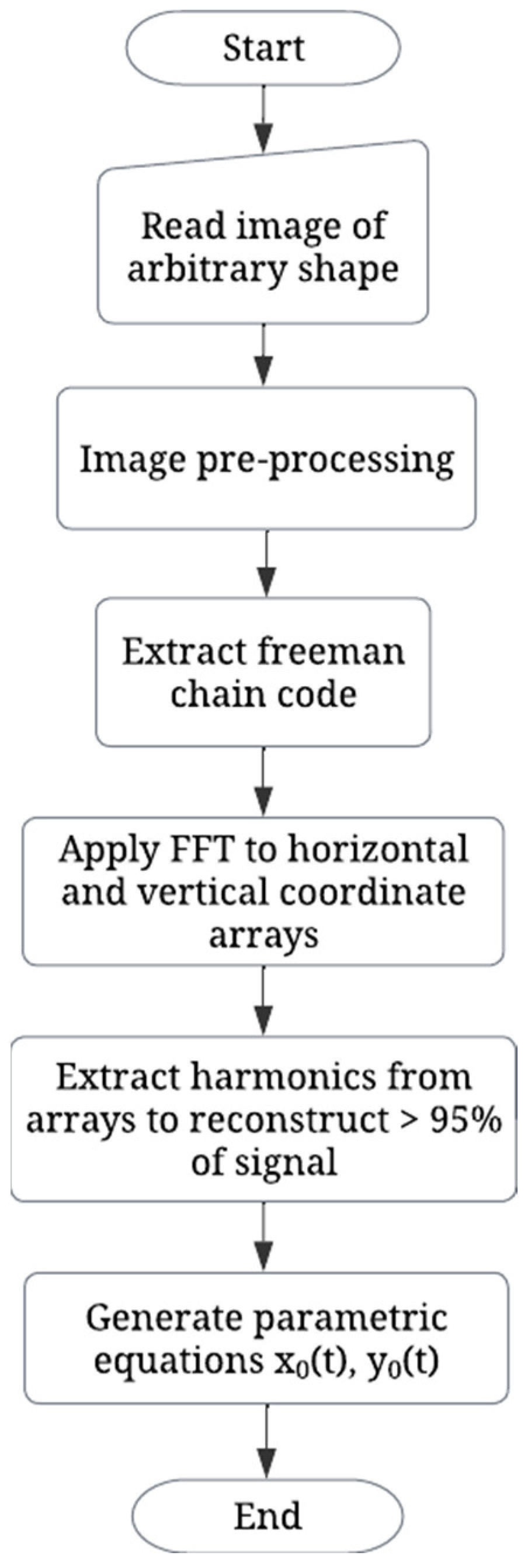
2.1. Signal Processing Algorithms

This proposal considers a black and white image of a closed curve as an input, drawn directly onto the screen or created from a predefined shape. In Figure 1, we present the flow diagram of the algorithm for image and signal processing required for extracting the harmonics of the horizontal and vertical waveforms that compose a given curve.
As illustrated in Figure 1, the algorithm begins by reading the image that includes an arbitrary shape and applies image pre-processing techniques, resizing, binarizing, and centering the image within a larger background. Then, to obtain the contour of the desired curve, the 8-connectivity scheme of the Freeman chain code is extracted from the two-dimensional array [22]. This process returns an array containing the extracted code and a coordinate that represents the starting (x, y) point. With this data, a pair of arrays is created, representing the horizontal and vertical coordinates that follow the shape of the given curve, both coordinate arrays are normalized and centered. Then, by applying the fast Fourier transform to each array and by adding sufficient harmonics to reconstruct at least 95% of the original shape, the parametric equations are estimated. These expressions are useful since they allow the generation of scalar beams with an intensity distribution that follows the prescribed curve. This is performed by extracting the phase term that shapes the phase of the beam along the curve, from the study of the expected complex field amplitude [12]. In the study, the method is limited to the realization of smooth optical patterns consisting of curves expressed by a super formula. In our proposal, we overcome this restriction by estimating the parametric equations x 0 t , y 0 t of a given curve c t . Estimating these expressions allows the use of the term Φ that shapes the phase of the beam along the curve [12] as
Φ r , t = e i ω 0 2 y x 0 t x y 0 t + i σ ω 0 2 0 t x 0 τ y 0 τ y 0 τ x 0 τ d τ .
In Equation (1), r = x , y indicates the plane where the two-dimensional curve is drawn with t 0 , T , σ is a free parameter for controlling the phase gradient along the curve and ω 0 is a constant that allows modifying the topological charge. Introducing this phase behavior in the complex field amplitude of a plane wave in the plane l = 0 , results in the expression that preserves beam shape during propagation along the axial direction
G r , 0 | c t , t 0 , T = 1 L 0 T Φ r , t c t d t
Since we are interested in testing the phase of the designed light beams under a common path interference configuration, that additionally allows for the capture of their individual intensity, two phase patterns of the same size are displayed on the SLM, side-by-side. In the following section, we present the experimental setup for these experiments.

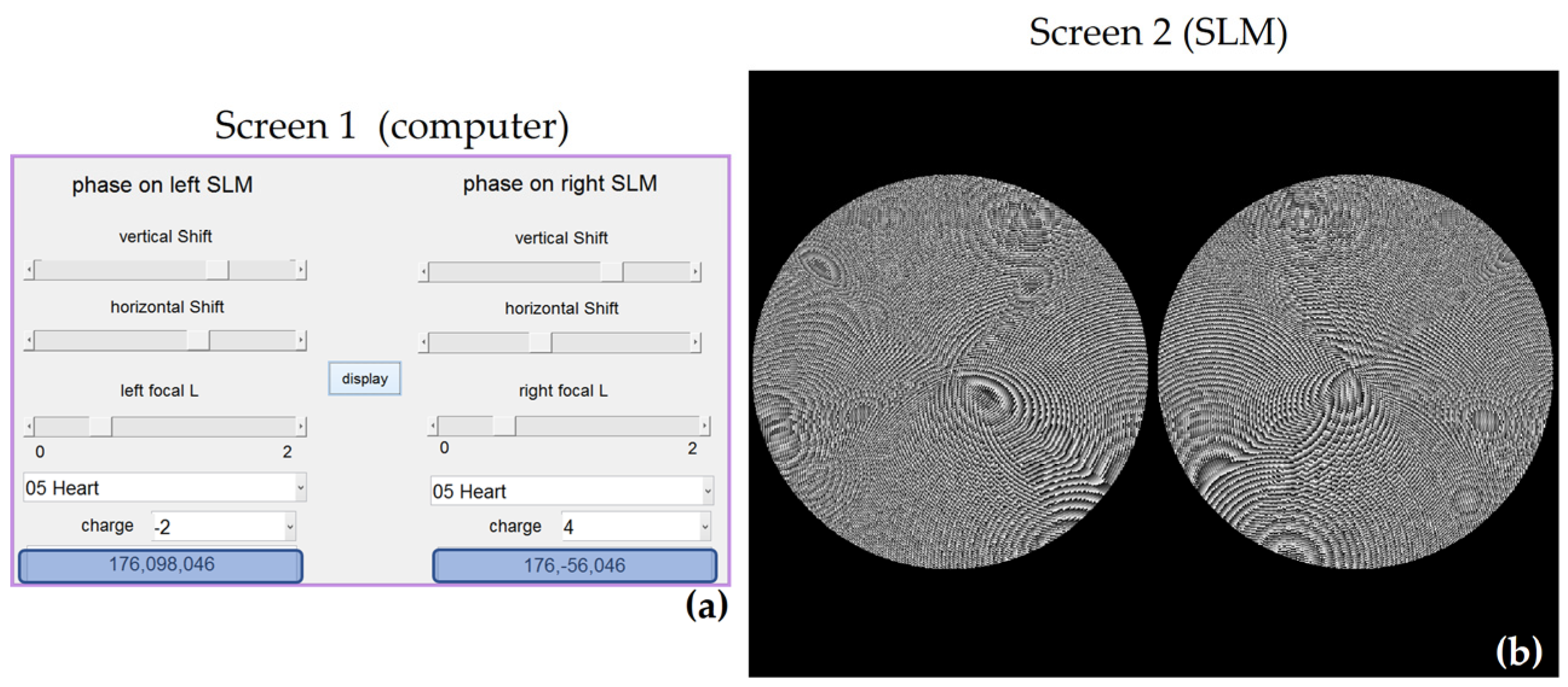
2.2. Experimental Setup

The experimental setup is depicted in Figure 2. We use a solid-state laser (Opus 532, from Laser Quantum, Stockport, UK) with a wavelength of 532 nm, we can operate it at low power for interference experiments and at high power (up to 2 W) in case of optical trapping. A reflective SLM (LC-R 2500, from Holoeye Photonics AG, Berlin, Germany) is used with a resolution of 1024 × 768 pixels (19 µm pixel pitch) and a phase modulation of 2π.
In Figure 2, a laser beam that has been expanded and collimated through lenses L1 and L2, is incident upon the entire active area of the spatial light modulator. After reflection a pair of selected shapes were encoded side-by-side over the active area of the SLM. Therefore, a pair of beams engineered in intensity and in phase, propagate and interfere at a distance, where a charge-coupled device camera is located. Considering that the SLM in use has an efficiency of 80% and that a pair of beams are reflected, each beam represents, at most, 40% of the power emitted from the laser. Implementing a configuration where the complete active area is used for displaying one phase pattern, improves the conversion efficiency to 80%.
When only one side of the SLM is in use, the camera can capture the intensity of the arbitrary shape previously designed. When both sides of the SLM are in use, interference can be achieved, and an analysis of the resulting interferogram would indicate the phase of the superposed light beams. An example of the interface executed on the computer and the corresponding phase images displayed on the SLM is presented in Figure 3.
The user interface from Figure 3a allows to select a focal length and a shift in the horizontal and vertical directions for a given shape, showing the selected values on the blue rectangles at the bottom. A topological charge is also selected for each shape and the corresponding phase is displayed on the SLM, as seen in Figure 3b.
Specifically, for demonstration of the phase gradient, a vortex beam can be encoded as a ring shape with our algorithm, allowing the generation of a pair of vortices that interfere, where the resulting interferogram could clearly demonstrate the topological charges interacting, as described in [23]. In the following section we present eight arbitrary shapes used as input for our algorithm and demonstrate their intensity and phase under this experimental setup.

3. Results

In this section, we describe the set of contours used as target for beam shaping and the parametric equations extracted using the proposed method. Then, we present the intensity images and the interferograms captured under the setup from Figure 2, to demonstrate the generation of the desired beams.

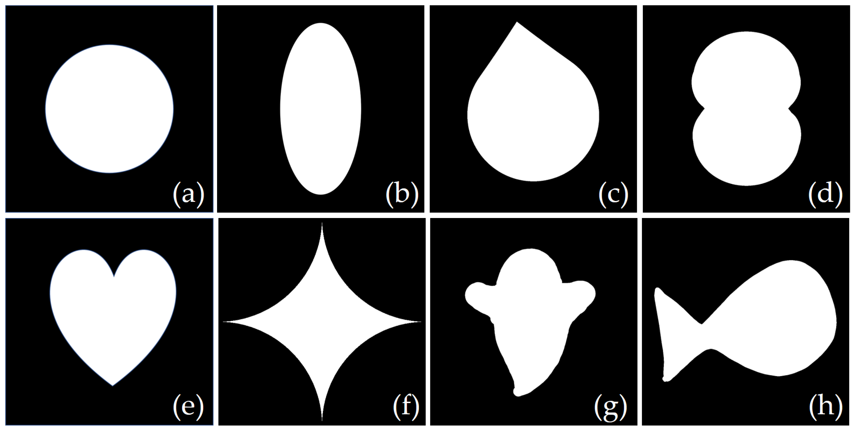
3.1. Estimation of Parametric Equations

A set of eight shapes, shown in Figure 4, was used for testing our method. These shapes were selected based on their common usage on beam shaping proposals [12,14,24], including some hand-drawn shapes too. This set includes common shapes with few harmonics; such as a ring (a) and an ellipse (b), known shapes with more harmonics; such as a droplet (c), a nephroid (d), a heart (e), an asteroid (f), and shapes drawn by hand with the contour of a ghost (g) and a fish (h).
Every shape in Figure 4 is read an analyzed under the presented approach, extracting the harmonics to approximate the curve that describes the contour of the shape. According to our algorithm, we extract sufficient harmonics to reconstruct at least 95% of an original form. In the case of Figure 4c,g, this amount was reduced to 92%, since more than nine non-zero harmonics were estimated, increasing the complexity of phase extraction when applying Equation (2). In Table 1, the estimated parametric equations are organized.
Considering that all equations from Table 1 are expressed in terms of cosine functions, we can recognize how, for the simplest curve in Figure 4a, the parametric equations approximate a cosine waveform in the horizontal direction and a sine waveform in the vertical direction, as expected. For more complex waveforms, a greater number of harmonics are required. For example, since Figure 4c has a sharp edge, the parametric equation for ‘y’ requires more harmonics compared to a smooth shape like Figure 4b. Figure 4d–f have known parametric equations, but since we approximate their shape through a linear combination of cosine waveforms, several terms are required. The last expressions in Table 1, for Figure 4g,h, require several harmonics for reconstruction since they show no symmetry being drawn directly by hand.

3.2. Testing the Intensity of the Designed Light Beams

By inserting the estimated equations from Table 1 into Equation (2), the phase holograms for the SLM are generated. In Figure 5, we present the intensity of the designed light beams.
Comparing the intensity images displayed in Figure 5 to the desired contour of the shapes shown in Figure 4, only minor differences are detected over the sharp edges in (c), (e), and (g). These differences are due the quantity of harmonics considered for reconstruction, that sum 95% of the energy for the shape in Figure 5e, and 92% for Figure 5c,g.

3.3. Testing the Phase Gradient of the Designed Light Beams

To demonstrate that the phase gradients were correctly encoded by manipulating the topological charge from Equation (1), the common path interference setup from Figure 2 is implemented. The off-axis interference of light beams is examined in Figure 6, where we selected to test with Gaussian beams and vortices with charges m = +2 and m = −2.
The experimental setup allows the off-axis interference between two oblique-incident vortex beams [23], providing a reference for visually locating the fork-shaped fringes within the interferograms from Figure 6. The interferograms from Figure 6 demonstrate that the phase gradient, encoded into the light beams through the topological charge m, corresponds with the observed fringes. In this section, we tested the encoded phase in a ring shape to obtain vortex interference, which has been widely studied [23,24].
In Figure 6a, a pair of Gaussian beams were superposed, displaying the straight fringes expected from the interference of plane waves. Then, Figure 6b,c show the interference of a Gaussian beam with a vortex beam, charges m1 = 2 and m2 = −2, respectively. The bright and dark fork patterns seen in Figure 6b,c confirm the result of these additions. Figure 6d,e show straight fringes from the interference of equally charged vortices, m1,2 = 5 and m1,2 = −5, respectively. Figure 6f represents the superposition of vortices with topological charges m1 = +2 and m2 = −2, showing a fork of bright fringes indicating a charge +4. Finally, Figure 6g shows a fork of dark fringes indicating a charge −4, from the off-axis interference of vortices with charges m1 = −2 and m2 = +2.
Additional interferograms were examined, producing straight and fork-shaped fringes in accordance with the superposition of a pair of vortices, encoded with orders varying from −5 to 5. The presented approach has allowed beam shaping in intensity by approximating an arbitrary shape through its parametric equations. Moreover, transforming a given curve into the equations that represent it, allows it to encode a phase gradient along every point of its trajectory through calculus (as presented in Equation (2)), offering in this way a solution for manipulating both intensity and phase gradient of an arbitrary shape.

4. Discussion

We have introduced and tested a method for beam shaping of arbitrary curves through the design of phase masks to display on a SLM. By using a SLM and few optical elements, we have been able to test the correct encoding of phase patterns, as presented in Figure 5 and Figure 6. This test has been restricted to a visual comparison in shape for the intensity images, while, for phase gradient, it has been quantitative by testing through the interferograms obtained from pairs of vortex beams.
Since the SLM is an active device, it offers a dynamic solution for beam shaping and additionally, given its large pixel array, it allows to encode more than one pattern over its active area. Moreover, we exploit the features of this device by designing beams that interfere in a common path interference setup. All these features may also be exploited from another active device, the digital micromirror device (DMD). Compared with a SLM, a DMD is usually chosen when faster modulation rates are required [25], at the expense of reducing the power efficiency. For optical trapping, this may be a drawback when the photon budget cannot be compromised. However, beam shaping at high speeds has been achieved when using a DMD in the off-axis regime, through diffusive media and through multimode fiber [25]. Additionally, with the development of optical nano printing [23], specifically through light controlled electric fields, the usage of optical imaging systems based on DMD as spatial light modulators offers a solution in nano-scale applications [25,26,27]. Considering that our approach for beam shaping may be applied using either a SLM or a DMD, a wider range of applications arise. In laser cutting [16], dynamic beam shaping increases the cutting speed and improves the cut edge quality. In optical trapping, manipulating the phase of light, both two-dimensional and three-dimensional structures can be programmed to line up, sort, or rearrange nano and micro-sized particles [15,20,28]. In biological cells, an indirect transportation of cells can be implemented through the design of an arbitrary curve or shape [29].
Expanding the reach of beam shaping, we currently find emerging applications that can benefit from the presented method, such as optical nanolithography and optothermal manipulation. These techniques involve delicate processing of advanced substrates to remove very thin layers, using high quality beam shaping. In optical nanolithography, the manufacturing of microelectronics by the semiconductor industry and the remarkable properties of graphene [18,27] have led the interest in managing arbitrary 2D patterns with both high throughput and high resolution. Optical patterning of graphene nanostructures with thermal manipulation is studied to facilitate the development of terahertz photonic devices, useful in biosensing and photon detection [18]. Then, compared with conventional optical trapping, heat-mediated optical manipulation techniques allow versatile control of matter of different compositions, shapes, and sizes [30]. This is performed by designing and exploring optothermo–matter interactions for transporting mass, where it is of interest to implement arbitrary trajectories with thermal gradients [30]. Research in nanomanipulation techniques has been active in the last five years [15,18,19,20,28] and could be greatly benefited from methods for encoding arbitrary trajectories through beam shaping.

5. Conclusions

We have presented a non-iterative method for beam shaping. The algorithm starts by representing an arbitrary shape as a binary two-dimensional image and then extracting the path that follows its contour using Freeman chain code and estimating its parametric equations by applying the fast Fourier transform to the horizontal and vertical waveforms. Using the estimated equations into the incident complex amplitude field (we have considered a plane wave) allows us to encode intensity and phase gradient along the desired path for the light beam and they have been experimentally generated.

Author Contributions

Conceptualization, A.S.-T. and V.R.-C.; methodology, A.S.-T. and V.R.-C.; software, A.S.-T.; validation, A.S.-T. and V.R.-C.; formal analysis, A.S.-T.; investigation, A.S.-T. and V.R.-C.; resources, V.R.-C.; data curation, A.S.-T.; writing—original draft preparation, A.S.-T.; writing—review and editing, A.S.-T. and V.R.-C.; visualization, A.S.-T. and V.R.-C.; supervision, A.S.-T. and V.R.-C.; project administration, V.R.-C.; funding acquisition, A.S.-T. and V.R.-C. All authors have read and agreed to the published version of the manuscript.

Funding

This research was funded by UC MEXUS-CONACYT, CN-20-149.

Data Availability Statement

Not applicable.

Conflicts of Interest

The authors declare no conflict of interest.

References

  1. Rhodes, P.W.; Shealy, D.L. Refractive Optical Systems for Irradiance Redistribution of Collimated Radiation: Their Design and Analysis. Appl. Opt. 1980, 19, 3545. [Google Scholar] [CrossRef] [PubMed]
  2. Veldkamp, W.B.; Kastner, C.J. Beam Profile Shaping for Laser Radars That Use Detector Arrays. Appl. Opt. 1982, 21, 345. [Google Scholar] [CrossRef] [PubMed]
  3. Wang, J.; Liang, Y. Generation and Detection of Structured Light: A Review. Front. Phys. 2021, 9, 345–356. [Google Scholar] [CrossRef]
  4. Serrano-Trujillo, A.; Anderson, M.E. Surface Profilometry Using Vortex Beams Generated with a Spatial Light Modulator. Opt. Commun. 2018, 427, 557–562. [Google Scholar] [CrossRef]
  5. Zhao, D.; Jia, C.; Ma, Y.; Yang, X.; Zhang, B.; Chu, W. High-Accuracy Surface Profile Measurement Based on the Vortex Phase-Shifting Interferometry. Int. J. Opt. 2021, 2021, 6937072. [Google Scholar] [CrossRef]
  6. Zhu, L.; Wang, A.; Wang, J. Free-Space Data-Carrying Bendable Light Communications. Sci. Rep. 2019, 9, 14969. [Google Scholar] [CrossRef] [Green Version]
  7. Yoshida, M.; Kozawa, Y.; Sato, S. Subtraction Imaging by the Combination of Higher-Order Vector Beams for Enhanced Spatial Resolution. Opt. Lett. 2019, 44, 883. [Google Scholar] [CrossRef] [PubMed]
  8. Kozawa, Y.; Matsunaga, D.; Sato, S. Superresolution Imaging via Superoscillation Focusing of a Radially Polarized Beam. Optica 2018, 5, 86. [Google Scholar] [CrossRef]
  9. Grier, D.G.; Roichman, Y. Holographic Optical Trapping. Appl. Opt. 2006, 45, 880. [Google Scholar] [CrossRef] [PubMed] [Green Version]
  10. Liu, Q.; Chew, K.-H.; Huang, Y.; Liu, C.; Hu, X.; Li, Y.; Chen, R.-P. Effect of Twisting Phases on the Polarization Dynamics of a Vector Optical Field. Photonics 2022, 9, 722. [Google Scholar] [CrossRef]
  11. Liu, C. Vortex Beam and Its Application in Optical Tweezers. J. Phys. Conf. Ser. 2020, 1549, 032012. [Google Scholar] [CrossRef]
  12. Rodrigo, J.A.; Alieva, T.; Abramochkin, E.; Castro, I. Shaping of Light Beams along Curves in Three Dimensions. Opt. Express 2013, 21, 20544. [Google Scholar] [CrossRef] [PubMed] [Green Version]
  13. Serrano-Trujillo, A.; Palafox, L.E.; Ruiz-Cortés, V. Engineering of Cylindrical Vector Fields with a Twisted Nematic Spatial Light Modulator. Appl. Opt. 2017, 56, 1310. [Google Scholar] [CrossRef]
  14. Mendoza-Hernández, J. Customizing Structured Light Beams with a Differential Operator. Opt. Lett. 2021, 46, 5232. [Google Scholar] [CrossRef]
  15. Li, J.; Hill, E.H.; Lin, L.; Zheng, Y. Optical Nanoprinting of Colloidal Particles and Functional Structures. ACS Nano 2019, 13, 3783–3795. [Google Scholar] [CrossRef]
  16. Levichev, N.; Herwig, P.; Wetzig, A.; Duflou, J.R. Towards Robust Dynamic Beam Shaping for Laser Cutting Applications. Procedia CIRP 2022, 111, 746–749. [Google Scholar] [CrossRef]
  17. Möhl, A.; Kaldun, S.; Kunz, C.; Müller, F.A.; Fuchs, U.; Gräf, S. Tailored Focal Beam Shaping and Its Application in Laser Material Processing. J. Laser Appl. 2019, 31, 042019. [Google Scholar] [CrossRef] [Green Version]
  18. Lin, L.; Li, J.; Li, W.; Yogeesh, M.N.; Shi, J.; Peng, X.; Liu, Y.; Rajeeva, B.B.; Becker, M.F.; Liu, Y.; et al. Optothermoplasmonic Patterning: Optothermoplasmonic Nanolithography for on-Demand Patterning of 2D Materials (Adv. Funct. Mater. 41/2018). Adv. Funct. Mater. 2018, 28, 1870299. [Google Scholar] [CrossRef]
  19. Nan, F.; Yan, Z. Synergy of Intensity, Phase, and Polarization Enables Versatile Optical Nanomanipulation. Nano Lett. 2020, 20, 2778–2783. [Google Scholar] [CrossRef]
  20. Li, J.; Zheng, Y. Optothermally Assembled Nanostructures. Acc. Mater. Res. 2021, 2, 352–363. [Google Scholar] [CrossRef]
  21. Zannotti, A.; Denz, C.; Alonso, M.A.; Dennis, M.R. Shaping Caustics into Propagation-Invariant Light. Nat. Commun. 2020, 11, 3597. [Google Scholar] [CrossRef] [PubMed]
  22. Gonzalez, R.C.; Woods, R.E. Digital Image Processing; Pearson: New York, NY, USA, 2018. [Google Scholar]
  23. Anderson, M.E.; Serrano, A.; Stinson, C.; Talamantes, A.; Miller, N.; Chaloupka, J.L. Spatial Manipulation of a Supercontinuum Beam for the Study of Vortex Interference Effects. Appl. Sci. 2020, 10, 1966. [Google Scholar] [CrossRef] [Green Version]
  24. Moreno, I.; Davis, J.A.; Womble-Dahl, T.; Cottrell, D.M. Azimuthal Multiple-Beam Interference Effects with Combinations of Vortex Beams. Opt. Lett. 2015, 40, 2341. [Google Scholar] [CrossRef]
  25. Turtaev, S.; Leite, I.T.; Mitchell, K.J.; Padgett, M.J.; Phillips, D.B.; Čižmár, T. Comparison of Nematic Liquid-Crystal and DMD Based Spatial Light Modulation in Complex Photonics. Opt. Express 2017, 25, 29874. [Google Scholar] [CrossRef] [Green Version]
  26. Zhuang, Z.; Ho, H.P. Application of Digital Micromirror Devices (DMD) in Biomedical Instruments. J. Innov. Opt. Health Sci. 2020, 13, 2030011. [Google Scholar] [CrossRef]
  27. Sharma, E.; Rathi, R.; Misharwal, J.; Sinhmar, B.; Kumari, S.; Dalal, J.; Kumar, A. Evolution in Lithography Techniques: Microlithography to Nanolithography. Nanomaterials 2022, 12, 2754. [Google Scholar] [CrossRef]
  28. Nan, F.; Yan, Z. Optical Sorting at the Single-Particle Level with Single-Nanometer Precision Using Coordinated Intensity and Phase Gradient Forces. ACS Nano 2020, 14, 7602–7609. [Google Scholar] [CrossRef]
  29. Chen, H.-C.; Cheng, C.-J. Holographic Optical Tweezers: Techniques and Biomedical Applications. Appl. Sci. 2022, 12, 10244. [Google Scholar] [CrossRef]
  30. Chen, Z.; Li, J.; Zheng, Y. Heat-Mediated Optical Manipulation. Chem. Rev. 2021, 122, 3122–3179. [Google Scholar] [CrossRef]
Figure 1. Algorithm for the estimation of parametric equations of a closed curve.
Applsci 13 03192 g001
Figure 2. Experimental setup for testing the intensity and phase of the engineered light beams.
Applsci 13 03192 g002
Figure 3. Encoding of phase patterns for beam shaping, (a) Computer interface, and (b) phase patterns displayed on the SLM.
Applsci 13 03192 g003
Figure 4. Set of shapes used as target for engineering intensity and phase gradient of light beams by estimating parametric equations; (a) ring, (b) ellipse, (c) droplet, (d) nephroid, (e) heart, (f) astroid, (g) ghost, and (h) fish.
Applsci 13 03192 g004
Figure 5. Intensity of the light beams designed by estimating the parametric equations of the shapes shown in Figure 4; (a) ring, (b) ellipse, (c) droplet, (d) nephroid, (e) heart, (f) astroid, (g) ghost, and (h) fish.
Applsci 13 03192 g005
Figure 6. Off-axis interference of engineered light beams. Gaussian beam with (a) a Gaussian beam, (b) a vortex with m = 2, (c) a vortex with m = −2. Vortices with charges (d) m1 = −2 m2 = −2, (e) m1 = 2 m2 = 2, (f) m1 = 2, m2 = −2, and (g) m1 = −2, m2 = 2.
Applsci 13 03192 g006
Table 1. Estimated parametric equations for shapes presented in Figure 4.
ShapeParametric Equation “x”Parametric Equation “y”
(a)
Ring
cos(t − 3.08)cos(t + 1.63)
(b)
Ellipse
cos(t − 3.06) + 0.11 cos(3t + 0.24)cos(t + 1.65) + 0.10 cos(3t − 1.33)
(c)
Droplet
−0.04 + cos(t + 3.11) + 0.05 cos(2t − 0.91)
+ 0.03 cos(3t − 2.43) + 0.01 cos(4t − 2.83)
0.24 + cos(t + 1.59) + 0.04 cos(2t + 0.37)
+ 0.05 cos(3t − 1.25) + 0.03 cos(4t − 2.56)
+ 0.02 cos(5t + 2.79) + 0.02 cos(6t + 0.71)
(d)
Nephroid
cos(t − 2.69) + 0.11 cos(3t + 1.39) + 0.06 cos(5t + 2.33)
+ 0.02 cos(7t − 2.95) + 0.02 cos(9t − 2.12) +
0.02 cos(11t − 1.26) + 0.01 cos(13t− 0.32)
cos(t + 2.03) + 0.05 cos(3t − 0.21)
(e)
Heart
cos(t − 3.04) + 0.04 cos(2t − 1.42)
+ 0.05 cos(3t − 2.86)
−0.47 + cos(t + 1.66) + 0.23 cos(2t − 2.96) +
0.04 cos(3t + 1.82) + 0.12 cos(4t + 0.35)
(f)
Astroid
cos(t − 3.14) + 0.31 cos(3t − 3.13) +
0.07 cos(5t − 3.13) + 0.05 cos(7t − 3.12) +
0.02 cos(9t − 3.11) + 0.01 cos(11t − 3.1)
cos(t + 1.57) + 0.32 cos(3t − 1.56) + 0.07 cos(5t + 1.59) + 0.03 cos(7t − 1.54) + 0.02 cos(9t + 1.61)
+ 0.01 cos(11t − 1.53)
(g)
Ghost
−0.03 + cos(t − 2.88) + 0.13 cos(2t + 1.75) +
0.05 cos(3t − 3.04) + 0.08 cos(4t + 2.81) +
0.05 cos(5t − 1.53) + 0.08 cos(6t + 2.84)
−0.25 + cos(t + 1.83) + 0.13 (cos2t − 2.45) +
0.11 cos(3t − 0.75) + 0.03 cos(4t − 1.96) +
0.07 cos(5t + 2.8) + 0.02 cos(6t + 1.29)
(h)
Fish
−0.13+cos(t − 2.71) + 0.06 cos(2t + 0.9) +
0.03 cos(3t − 2.25) + 0.03 cos(4t + 2.07)
0.2 + cos(t + 1.79) + 0.23 cos(2t − 0.92)
+ 0.33 cos(3t − 3.14) + 0.2 cos(4t − 2.78) +
0.02 cos(5t − 2.02) + 0.05 cos(6t + 1.68)
Disclaimer/Publisher’s Note: The statements, opinions and data contained in all publications are solely those of the individual author(s) and contributor(s) and not of MDPI and/or the editor(s). MDPI and/or the editor(s) disclaim responsibility for any injury to people or property resulting from any ideas, methods, instructions or products referred to in the content.

