Abstract
Spectrum-sensing algorithms are one of the effective solutions to the problem of the underwater spectrum resource constraint. However, because the underwater acoustic channel is one of the most complex channels, it has many characteristics, such as a limited communication bandwidth, multipath effect, and ocean noise, all of which render the spectrum detection more difficult. As basic spectrum-sensing algorithms, energy detection algorithms are widely used in underwater acoustic communication and radio. However, most of the existing dual-threshold energy detection methods do not judge the signals with energy values between the thresholds or discard them directly. In this paper, a double-threshold centralized co-operative detection algorithm is proposed to solve this problem. In this algorithm, each sensing user makes a judgment independently, and if the historical energy statistics are between the thresholds, the number of sampling points is increased, and the judgment is made again. In the centralized collaborative sensing algorithm, each sensing user’s results are sent to the fusion center, which uses the OR judgment criterion to make decisions. Simulation results show that this algorithm can improve the detection performance and reduce the error rate.
1. Introduction
Since the 20th century—from cable to optical cable, wired to wireless, analog to digital, and 1G to 5G—land communication has undergone rapid development and change. However, in the vastness of the ocean, the development of marine communication obviously lags behind that of land communication due to the complex and changing marine environment and the difficulty of offshore construction [1]. However, humans have historically been in awe of the ocean, which lies in both the Southern and Northern Hemispheres and is larger than the land area in either hemisphere. Although there are many setbacks and challenges in the development of marine communication, the exploration of the ocean is of great significance and value. In addition to having a very low frequency, electromagnetic waves attenuate quickly in water, and strong ultra-long waves can penetrate only approximately 100 m past the surface of water. Light waves are affected by absorption and scattering in water and can be transmitted only for short distances. Even the most distant blue and green lasers can be transmitted only for a few hundred meters underwater. Because sound waves can travel a relatively long distance in water, underwater acoustic communication is the main means of underwater wireless information transmission [2]. In the past decade, underwater acoustic networks (UANs) [3,4,5,6,7,8,9,10] have attracted significant interest from both academia and industry due to the wide range of applications of UANs, including underwater environment monitoring. Various coexisting applications in oceans have led to multiple underwater networks sharing channel resources with each other [11]. Underwater acoustic channels are the medium of sound wave propagation and the foundation of underwater acoustic networks. Ian F. Akyildiz et al. [12] examined several key aspects of hydroacoustic communication, discussing various architectures for two- and three-dimensional underwater sensor networks and detailing the characteristics of underwater channels. Zhang Yuzhi et al. [13] firstly explored the unique propagation feature of underwater acoustic channels. Secondly, they analyzed how the channel variations affect cognitive communication and networks. Thirdly, they investigated the constraints for cognitive networks relayed by underwater acoustic channels. Lastly, they drew a modeling scheme with both physical-layer and upper-layer considerations for the cognitive network. Time-varying multi-path propagation and non-Gaussian noise are two of the major factors that limit acoustic communication performance in shallow water. The simple Rayleigh fading ray model yields good agreement with data collected at ranges of 50 m to 1020 m. The fading statistics of interfering rays could also be explained with the model [14].
Yu Luo et al. [11] proposed the concept of a cognitive acoustic network. By sensing the surrounding spectrum usage, cognitive acoustic (CA) users in underwater cognitive acoustic networks (UCANs) are able to intelligently detect whether any portion of the spectrum is occupied and change their frequency, power, or even other operation parameters to temporarily use the idle frequencies without interfering with other networks. Spectrum sensing is a fundamental part of such cognitive acoustic networks. Mitola J. I. [15] defined and developed a cognitive radio architecture that organizes the knowledge of the radio domain into data structures that can be processed in real time, incorporating machine learning and natural language processing techniques into software radio. Simon Haylin [16] showed that it is possible to combine cognitive radio with underwater acoustic communication, which provides a new research direction for the development and progress of underwater communication technology in the future. Xu Jianxia et al. [17] proposed a double-threshold energy detection [18,19,20,21,22,23,24] method which can effectively solve the problem where traditional energy detection algorithms are prone to missing detection when the signal-to-noise ratio is low, which may reduce the detection performance of the system. A threshold used for primary user detection is highly susceptible to unknown or changing noise levels. In co-operative sensing, users rely on the variability of the signal strength at various locations. We expect that a large network of cognitive radios with sensing information exchanged between neighbors would have a better chance of detecting the primary user compared to individual sensing [25]. Major challenges appear due to multipath fading, hidden terminal problems, shadowing, and receiver noise uncertainty. To mitigate the impact of these issues, co-operative spectrum sensing turned out to be an effective method for improving performance [26]. Zeng F. et al. [27] developed a decentralized co-operative spectrum-sensing approach that fuses the benefits of compressive sampling and consensus optimization. However, when the number of cognitive users is very large, the bandwidth for reporting their sensing results to the common receiver is very large. Sun C. et al. employed a censoring method with quantization to decrease the average number of sensing bits to the common receiver [28]. However, it does not indicate how to judge a signal for which the energy value is between two thresholds.
The main structure of the remainder of this paper is as follows: The second section introduces the channel transmission model used in this paper. The third part analyzes the traditional energy detection algorithm and principle. The fourth part introduces the collaborative spectrum detection algorithm, and the fifth part introduces the algorithm principle and implementation flow chart. The sixth section simulates and compares the algorithm of this paper with several traditional energy detection algorithms and analyzes and discusses the drawbacks of each. The seventh section summarizes the overall structure and ideas of the paper and analyzes the effectiveness of the proposed algorithm.
2. Underwater Acoustic Channel Transmission Model
Underwater communication based on sonar without exception should use the research results of underwater acoustic channels as its solid foundation. Therefore, to achieve the desired effect of advanced underwater acoustic signal processing, a deep grasp of the effects of underwater acoustic channels on the attenuation, distortion, and fluctuation of underwater acoustic signals to achieve channel matching is necessary [29]. Some physical effects in the hydroacoustic channel can have a large impact on the communication performance, such as Rayleigh and Rice fading, time delay expansion, and Doppler expansion. There are many factors that produce these effects, and the regularity is complex; these are the elements that need extra attention when the hydroacoustic channel is simulated.
The process of sound wave propagation is actually a fluctuation process which can be described by the fluctuation equation. The fluctuation equation is as follows [30]:
is the Laplace operator, P is the sound pressure, and C is the speed of sound. The propagation process of sound waves is described by the sound field model; sound field analysis essentially solves the fluctuation equation to finally obtain the law of sound wave propagation. Because this fluctuation equation is for an ideal homogeneous medium with small-amplitude acoustic waves, in the actual ocean channel, the approximate solution is generally derived based on different classes of sound field models.
Commonly used sound field models are as follows: (1) Ray theory model: The sound waves are used to propagate the sound energy. The sound waves from the sound source follow different paths to the receiving point, so the received sound energy is the superposition of all the sound waves. (2) Multipath expansion model: The whole channel is considered to be a network system in which the sound source and the receiver are in a stationary state, and the sound velocity distribution is vertically stratified. (3) Normal mode model: When a normal mode is used to describe sound propagation, each eigenfunction corresponds to one solution of the fluctuation equation. The advantages are high accuracy and low computation for low-frequency applications of the model. The remaining models are (4) the fast field model and (5) the parabolic model.
The transmitted signal will undergo multiple reflections in seawater and finally reach the receiver. Figure 1 shows the acoustic wave transmission model, which is based on the ray theory model, demonstrating several different paths of acoustic wave propagation: the direct path and the propagation path that undergoes multiple reflections. Moreover, these propagation paths are the key to calculating the final received signal.
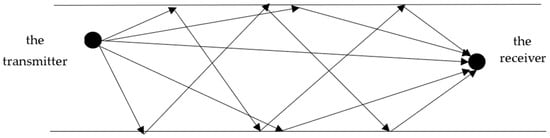
Figure 1.
The acoustic propagation model.
However, the channel is complex and variable, not only with ocean noise, but also with the attenuation, propagation delay, and Doppler effect. Therefore, the simulation of a hydroacoustic channel needs to consider various factors. The acoustic propagation model is as follows:
Figure 2 shows the intrinsic path model schematic. The transmission signal is subject to a different attenuation and propagation delay on different propagation paths. The interference received by the signal in the channel, such as delay attenuation and the Doppler effect, is simulated as a random component, taken as obeying a Gaussian distribution, and superimposed with the principal component, and it finally constitutes the channel output. Table 1 summarizes the main notation that is used in this paper.
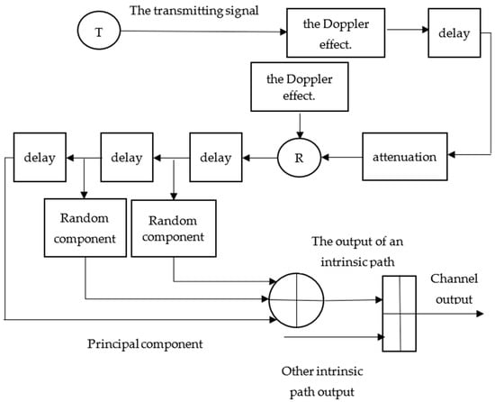
Figure 2.
Intrinsic path model schematic.

Table 1.
The main notation that has been used in the paper.
3. Traditional Energy Detection Algorithm and Principle
Energy detection is the most classic and basic algorithm in spectrum-sensing technology. The type of signal is not limited, and the application range is wide. Its core is to judge the state of the main user by calculating the energy value of the signal. Energy detection can be realized in two ways:
- (1)
- The sampled value of the time-domain signal is modulated, and the sum of the modulus squared of all sampling points is calculated.
- (2)
- FFT conversion is performed on the frequency-domain signal, and the sum of the squares of the moduli of all sampling points is calculated.
Figure 3 shows the flow chart of energy detection. The signal is first passed through a filter to filter out unnecessary frequency bands and is then sampled. The amplitude is then calculated for each sample point, and the sum of the modulus squares y of all samples is compared to a threshold value to determine if the band is idle.
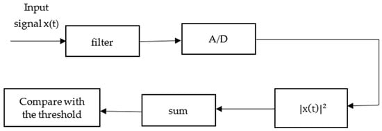
Figure 3.
Flow chart of energy detection.
The calculation method of the signal energy value is as follows:
N is the number of sampling points, and y is the energy value of the signal.
The binary hypothesis model is used to represent its detection process, as follows:
indicates that the frequency band is idle, indicates that the frequency band is occupied, and stands for noise signal.
When the number of sampling points N is large enough, y follows the Gaussian distribution.
represents the variance of the noisy signal, and represents the average power of the signal. The main indicators used to measure perception performance are as follows: (1) False alarm probability: When the frequency band is occupied, the detection result is idle. (2) Missed detection probability: When the frequency band is idle, the detection result is occupied. (3) Detection probability: The detection result is the same as the actual frequency band occupancy. The calculation method is as follows:
where is the threshold value, and is the right-tail function of the standard normal distribution. Figure 4 shows the energy detection diagram of a single threshold.
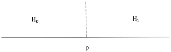
Figure 4.
Energy detection diagram of a single threshold.
If the energy value of the signal is greater than , it is in the state, and the frequency band is occupied. If it is less than , it is in the state, and the channel is not occupied. There are two kinds of calculations of the threshold value x: (1) known false alarm probability, and (2) known missed detection probability. The specific calculation method is as follows:
Figure 5 shows the energy detection diagram of the double threshold, the detection principle of which is similar to that of the single threshold.
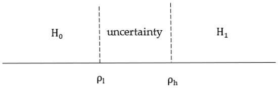
Figure 5.
Energy detection diagram of the double threshold.
The decision rules of the double-threshold energy detection algorithm are as follows: if the energy value of signal y is greater than , the main user signal exists. If the signal energy value y is less than , then the main user signal does not exist. When the signal energy value y is between two thresholds, it is an uncertain region. Three performance indicators are shown as follows:
4. Collaborative Spectrum Detection Algorithm
Multiple users perform collaborative detection and send their detection information to the fusion center. The fusion center fuses the received information and then makes a final decision based on the decision rules. It can alleviate the hidden terminal problem of single-user energy detection. Collaborative spectrum detection models can be divided into three categories: (1) Centralized collaborative spectrum detection [31]: The fusion center adjudicates the detection information sent by the sensing users and later returns the results to each sensing user. (2) Distributed collaborative spectrum detection [32]: Each node senses independently and exchanges sensing information to self-determine which bands can be accessed. The third model is (3) relay-forward co-operative spectrum detection [33]. The commonly used collaborative detection algorithms are mainly the centralized collaborative detection algorithm and the distributed collaborative detection algorithm. However, the distributed collaborative detection algorithm requires data exchange between nodes, which increases the system overhead and renders the algorithm difficult to use, so this paper uses the centralized collaborative detection algorithm.
Generally, there are two fusion rules for the fusion center: (1) Soft merge: The fusion center directly processes the original sensory information from the sensing user. Commonly used collaboration criteria are equal gain combining, maximum ratio combining, and selective combining. (2) Hard merge: The user judges the signal and sends the result to the fusion center for fusion. The commonly used judgment rules are as follows: (1) AND criterion: If the detection results of all users are (band occupied), the decision is H1. (2) OR criterion: If the detection result of one user is , the judgment is . (3) K out of N criterion: As long as the detection result of K users is , the judgment is .
When single-threshold collaborative detection with different decision rules is used, the false alarm probability and detection probability are expressed as follows:
5. Improved Double-Threshold Co-Operative Detection Algorithm
In view of the fact that most double-threshold detection algorithms are difficult to judge or temporarily difficult not to judge, or these algorithms directly discard signals for which the energy values are between double thresholds, a re-sensing algorithm based on historical sensing information is proposed.
The algorithm is implemented as follows:
- (1)
- A random signal is generated, and the following parameters are calculated:
- Attenuation: The fading effect has mainly fast fading and slow fading, and this paper analyzes and calculates mainly the fading caused by the multipath effect.
- Delay: This leads to a broadening of the received signal compared to the original signal and also causes frequency-selective fading.
- Doppler shift: This is caused by the relative motion of the transmitter and receiver or the flow of seawater. The Doppler frequency shift expression is as follows:is the velocity of sound, is the relative velocity of the motion between the transmitter and the receiver, and is the angle between the relative motion velocity and the signal transmission direction at the transmitter.
- Ocean noise with stack variance . Primary and random components are generated.
- (2)
- The energy value of the signal is calculated according to Formula (2). The high and low thresholds can be obtained by Formulas (11) and (12). The specific expression is as follows:
- (3)
- The calculated energy statistics are compared with the two thresholds. The algorithm flow chart is shown in Figure 6.
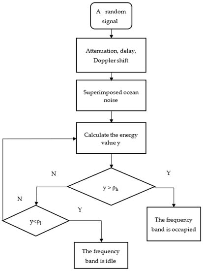 Figure 6. The algorithm flow chart.
 - (4)
- If the energy value of the signal is between the two thresholds, the N1 sampling points are added, the energy value and two threshold values are recalculated, and re-sensing is performed. The decision rule selection is based on the OR criterion.The specific calculation method of the energy value and the high and low thresh- olds is as follows:
- (5)
- The detection probability is computed. Firstly, the single-threshold energy detection algorithm is compared with the double-threshold energy detection algorithm, and the analysis verifies whether the double-threshold energy detection algorithm is more advantageous in the signal-to-noise environment simulated in this paper. Secondly, the traditional collaborative detection algorithms that currently exist are simulated to analyze their respective advantages and disadvantages and to analyze whether the OR criterion collaborative detection algorithm can achieve better results. Finally, the improved two-threshold collaborative detection algorithm proposed in this paper is compared with the traditional two-threshold collaborative detection algorithm to verify the feasibility of the proposed algorithm.
6. Results and Discussion
6.1. Analysis of the Simulation Results
The input signal waveform is shown in Figure 7. The input signal uses a random digital signal , inverting to obtain the signal . These two signals are then sampled at 2500. Finally, FSK modulation is performed to obtain two carriers. The input signal is obtained by summing the two carriers.
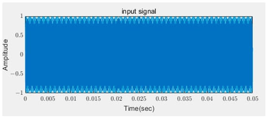
Figure 7.
Input signal simulation diagram.
In addition, because of the delay of each intrinsic signal, it is necessary to complement the zero before and after the signal when the signals are superimposed, so that the length of each intrinsic signal is the same.
The relevant parameters of the intrinsic path model are shown in Table 2.
Table 2.
The relevant parameters of the intrinsic path model.
The attenuation and delay of each intrinsic path are shown in Table 3; a negative sign in a value indicates a phase change of 180°.
Table 3.
The attenuation and delay of each intrinsic path.
Figure 8 shows the output signal of the channel, which can be seen as a signal with severe interference and a significant time delay. Because the output waveform is a superposition of output waveforms from different eigenpaths, the features of every sub-waveform are eventually displayed on the total output waveform. In addition, Gaussian narrowband noise is present in each eigenpath signal, so the amplitude of the output waveform is modulated, and its envelope is random narrowband noise. This is the reason the waveform of the total output signal will show a random undulation phenomenon. The speed of sound propagation in seawater is about 1500 m/s, but sound waves are affected by a variety of factors, such as sea depth, salinity, temperature, etc. The variation in the speed of sound, which in turn leads to the generation of the propagation time delay, is expressed as follows:
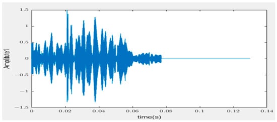
Figure 8.
The output signal of the channel.
is the speed of sound (m/s), T is the temperature (°C), S is the salinity, and Z is the depth (m).
In the simulation process of the proposed algorithm, there are three users participating in the collaborative detection algorithm, there were 1000 Monte Carlo simulation cycles, the false alarm probability pf is 1 × 10⁻⁵, and the missed detection probability pm is 0.01. The numbers of sample points are N = 4000, and N1 = 1000. Figure 9, Figure 10 and Figure 11 show the experimental comparison between the proposed algorithm and the various traditional algorithms in this paper to verify the effectiveness of the proposed algorithm from different aspects.
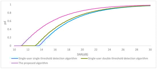
Figure 9.
Simulation comparison chart.
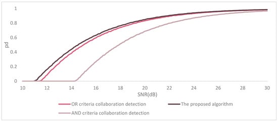
Figure 10.
The algorithm simulation experiment results.
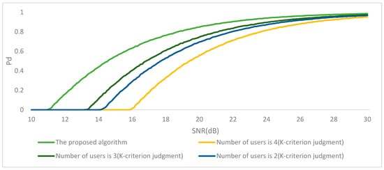
Figure 11.
The simulation results.
Three different simulation comparison experiments were conducted separately. First, the proposed algorithm was compared with two algorithms with the same number of users but a different number of thresholds. Second, it was compared with two traditional collaborative energy detection algorithms. Finally, because the parameter k in the k-verdict criterion in the collaborative detection algorithm is adjustable, a simulation comparison was performed for the case of a different number of users participating in the verdict.
Figure 9 shows the results of comparing the proposed algorithm with two algorithms which both involve single users but involve a different number of thresholds. In general, at low signal-to-noise ratios, the difference in power between the signal and the noise is small, resulting in far worse detection than double-threshold energy detection algorithms. As shown in Figure 9, in the signal-to-noise environment simulated in this paper, the double-threshold detection algorithm is overall better than the single-threshold detection algorithm. This is because the traditional single-threshold detection algorithm is more prone to false detection if there is burst noise or other interference, resulting in the user not being able to accurately use the idle bandwidth.
The algorithm in this paper uses a centralized collaborative detection algorithm, and the fusion center can use different fusion judgment rules. Thus, simulation experiments are conducted for the collaborative detection algorithm based on different judgment rules.
Under the condition that the probability of a missed detection and the probability of a false alarm are constant, three users are involved in collaborative detection. The following algorithms are simulated and compared: (1) Double-threshold OR criterion collaborative detection: As only one of the three users determines that the band is vacant, the final detection result is that the band is not used. (2) Double-threshold AND criterion co-operative detection algorithm: All three users are judged to be band-occupied, and then the final judgment is that they are in a state in which the band is occupied by the primary user. The third algorithm is (3) the algorithm proposed in this paper. The simulation results are shown in Figure 10.
From Figure 10, it can be seen that the proposed algorithm in this paper already has detection results in an environment with a signal-to-noise ratio of 11 dB, and the detection probability is up to 0.986. The AND criterion collaborative detection algorithm requires the same detection results for all users, so the possibility of generating false detections is greater than that for the other two collaborative algorithms. However, the OR criterion collaborative detection algorithm is less affected by the environment in which the user is located; it can also be seen from Figure 10 that the detection results are much less effective than those of the other two algorithms. Different decision rules can achieve different effects in collaborative detection, and the OR criterion has a better effect. On this basis, the algorithm proposed in this paper improves the detection performance.
Because k represents the number of sensing users in the k-fusion adjudication criterion, the principle is that the idle band is detected by all k users before the fusion center determines that idle bands exist. k is adjustable, so collaborative detection algorithms using k-criteria fusion judgments can have different detection effects. This simulation experiment lists three collaborative detection algorithms using k-criteria fusion judgments for various numbers of users, with the number of users being two, three, and four, respectively. The simulations of the proposed algorithm and these three algorithms are compared as follows.
Figure 11 shows the simulation results.
As can be seen from the figure, although the k-fusion judgment criterion can be used to find the optimal effect by adjusting the parameters, the process is long and time-consuming, especially in the case of many perceptual users. The more k values there are that can be chosen, the more possible effects there are, and the greater the difficulty of tuning the parameters.
6.2. Feasibility Analysis
The algorithm proposed in this paper was implemented in simulation and is based on the traditional energy detection algorithm, which is one of the spectrum-sensing algorithms with a wide range of applications and low algorithm complexity. In addition, the transmitted signal is synthesized to pass through the simulated hydroacoustic channel to obtain the received signal, and the values of the relevant parameters are given. However, in the actual hydroacoustic channel, the actual parameter values will be different from those set during simulation, such as temperature and humidity. Moreover, these factors will affect the transmission of acoustic waves. Thus, the proposed algorithm framework in this paper can be implemented in a near real-time manner, but the simulation experimental results will be slightly different from the actual experimental results.
6.3. Sea Experiment Design
To verify the effectiveness of the proposed algorithm in a real underwater environment, the corresponding sea experiments are designed. The topology of the experiments is shown in Figure 12. The experiment includes a central control node and three sensing nodes (SNs); the transmission distances from the central control node to SN1, SN2, and SN3 are 936 m, 1120 m, and 1254 m. The developed underwater communication unit is used at both the transmitter and receiver ends. The unit has four input channels and one output channel, which can be selected according to different applications.
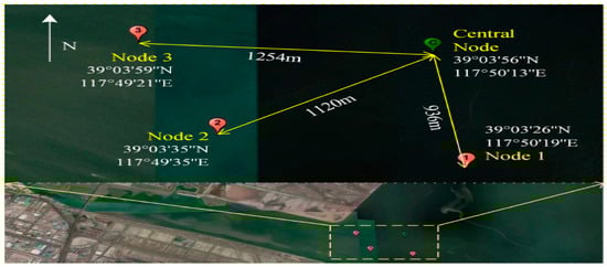
Figure 12.
The topology of the experiments.
Figure 13 shows the time-frequency diagram of the request-to-send (RTS) packets received by the three nodes for spectrum sensing. We observed that there are multiple narrowband interferences in the underwater environment, but only three of them affecting the communication, that is, in the communication band (21–27 kHz) range. Table 4 summarizes the BER performance of the three nodes for different schemes. As Table 4 shows, the AND criteria collaboration detection scheme still shows the worst performance, and the BER of the proposed algorithm is reduced compared to the traditional OR criterion collaborative detection scheme, which proves the effectiveness of the proposed spectrum-sensing scheme.
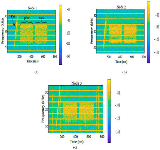
Figure 13.
The time-frequency diagram of the RTS packets received by the three nodes for spectrum sensing: (a) node 1; (b) node 2; and (c) node 3.
Table 4.
The BER performance of the three nodes for different schemes.
7. Conclusions
Underwater acoustic communication is a promising form of technology. The concept of cognitive underwater acoustic networks originated from cognitive radio and is the basis for underwater communication technology. One of the difficulties in applying cognitive radio technology to hydroacoustic communications is that the radio channel is very different from the hydroacoustic channel, which is one of the most complex and variable channels. Thus, a full understanding of the characteristics and physical effects of the hydroacoustic channel is needed for better simulation and a solid foundation for the next step of spectrum sensing. Considering the shortage of underwater spectrum resources, spectrum detection technology must be urgently advanced. However, because the research in this paper is not in the hydroacoustic channel, the existing hydroacoustic channel model is used for the simulation experiments. Because the hydroacoustic signal in the channel will be affected by a variety of factors, such as absorption loss, attenuation, and multipath effects, there are many challenges in applying the energy detection algorithm from radio technology to underwater communication. Understanding the different characteristics of underwater channels and selecting a suitable transmission model for underwater channels would allow the traditional two-threshold detection algorithm to be better applied to underwater communication. In this study, improvements were made in the traditional double-threshold energy detection algorithm; the proposed algorithm takes into account signals for which the energy values are between the two thresholds and uses a co-operative sensing algorithm to detect the signals step by step. A simulation comparison of several conventional energy detection algorithms was performed separately, and the results show that the proposed algorithm achieves its optimal effect when the number of users and the signal-to-noise ratio are different.
Author Contributions
Methodology, J.Z. and R.Z.; writing—original draft preparation, J.Z.; review and editing, J.Z. and R.Z.; supervision, R.Z. and Q.W. All authors have read and agreed to the published version of the manuscript.
Funding
This research was funded by the Tianjin Intelligent Manufacturing Special Fund Project—Underwater Heterogeneous Node Communication and Positioning Integrated Ad Hoc Network System Research and Development, Project No. 20201207 and Tianjin Sino-German University of Applied Sciences Video Image Intelligent Analysis and Processing Technology Innovation Team and Tianjin “131” Innovative Talent Team.: 201912.
Institutional Review Board Statement
Not applicable.
Informed Consent Statement
Not applicable.
Data Availability Statement
Not applicable.
Conflicts of Interest
The authors declare no conflict of interest.
References
- Wen, W.; Zhu, Y.; Xing, C.; Yang, T.; Xia, M.; Chen, E. The state of the art and challenges of marine communications. Sci. Sin. Inf. 2017, 47, 677–695. (In Chinese) [Google Scholar] [CrossRef]
- Zhu, M.; Wu, Y. Development of Underwater Acoustic Communication Technology. Proc. Chin. Acad. Sci. 2019, 34, 289–296. [Google Scholar] [CrossRef]
- Yang, L. The Research of Spectrum Detection in Cognitive Underwater Acoustic Communication. Ph.D. Thesis, Jiangsu University of Science and Technology, Zhenjiang, China, 2015. [Google Scholar]
- Cui, J.H.; Kong, J.; Gerla, M.; Zhou, S. The challenges of building mobile underwater wireless networks for aquatic applications. IEEE Netw. 2006, 20, 12–18. [Google Scholar]
- Su, Y.; Xu, Y.; Pang, Z.; Kang, Y.; Fan, R. HCAR: A Hybrid Coding-Aware Routing Protocol for Underwater Acoustic Sensor Networks. IEEE Int. Things J. 2023. early access. [Google Scholar] [CrossRef]
- Casari, P.; Zorzi, M. Protocol design issues in underwater acoustic networks. Comput. Commun. 2011, 34, 2013–2025. [Google Scholar] [CrossRef]
- Guo, Z.; Wang, B.; Xie, P.; Zeng, W.; Cui, J.H. Efficient error recovery with network coding in underwater sensor networks. Ad Hoc Netw. 2009, 7, 791–802. [Google Scholar] [CrossRef]
- Su, Y.; Guo, L.; Jin, Z.; Fu, X. A Voronoi-Based Optimized Depth Adjustment Deployment Scheme for Underwater Acoustic Sensor Networks. IEEE Sens. J. 2020, 20, 13849–13860. [Google Scholar] [CrossRef]
- Stojanovic, M. On the relationship between capacity and distance in an underwater acoustic communication channel. ACM SIGMOBILE Mob. Comput. Commun. Rev. 2007, 11, 34–43. [Google Scholar] [CrossRef]
- Su, Y.; Guo, L.; Jin, Z.; Fu, X. A Mobile-Beacon-Based Iterative Localization Mechanism in Large-Scale Underwater Acoustic Sensor Networks. IEEE Internet Things J. 2021, 8, 3653–3664. [Google Scholar] [CrossRef]
- Luo, Y.; Pu, L.; Zuba, M.; Peng, Z.; Cui, J.-H. Challenges and opportunities of underwater cognitive acoustic networks. IEEE Trans. Emerg. Top. Comput. 2014, 2, 198–211. [Google Scholar] [CrossRef]
- Akyildiz, I.F.; Pompili, D.; Melodia, T. Underwater acoustic sensor networks: Research challenges. Ad Hoc Netw. 2005, 3, 257–279. [Google Scholar] [CrossRef]
- Wang, A.; Li, B.; Zhang, Y. Underwater acoustic channels characterization for underwater cognitive acoustic networks. In Proceedings of the 2018 International Conference on Intelligent Transportation, Big Data & Smart City (ICITBS), Xiamen, China, 25–26 January 2018; pp. 223–226. [Google Scholar]
- Chitre, M.; Potter, J.; Heng, O.S. Underwater acoustic channel characterisation for medium-range shallow water communications. In Proceedings of the Oceans’ 04 MTS/IEEE Techno-Ocean’04 (IEEE Cat. No. 04CH37600), Kobe, Japan, 9–12 November 2004; pp. 40–45. [Google Scholar]
- Mitola, J.I. Cognitive radio. An Integrated Agent Architecture for Software Defined Radio. Ph.D. Thesis, Royal Institute of Technology, Stockholm, Sweden, 2002. [Google Scholar]
- Haykin, S. Cognitive dynamic systems. In Cognitive Informatics for Revealing Human Cognition: Knowledge Manipulations in Natural Intelligence; IGI Global: Hershey, PA, USA, 2013; pp. 250–260. [Google Scholar]
- Xu, J.; Liu, H.; Liu, K. Double Thresholds Energy Detection Algorithm in Cognitive Radio. J. Wuhan Univ. Technol. Inf. Manag. Eng. 2011, 33, 529–532+535. [Google Scholar]
- Chen, Y. Improved energy detector for random signals in Gaussian noise. IEEE Trans. Wirel. Commun. 2010, 9, 558–563. [Google Scholar] [CrossRef]
- Zeng, Y.; Liang, Y.C.; Zhang, R. Blindly combined energy detection for spectrum sensing in cognitive radio. IEEE Signal Process. Lett. 2008, 15, 649–652. [Google Scholar] [CrossRef]
- Nasrallah, A.; Abdelkrim, H.; Boukaba, T.; Baudoin, G.; Messani, A. Energy detection with adaptive threshold for cognitive radio. In Proceedings of the 2018 International Conference on Communications and Electrical Engineering (ICCEE), El Oued, Algeria, 7–18 December 2018; pp. 1–5. [Google Scholar]
- Zan, L.; Xihong, C.; Zedong, X. A novel double-threshold energy detection based on correlativity. In Proceedings of the 2019 IEEE 9th International Conference on Electronics Information and Emergency Communication (ICEIEC), Beijing, China, 12–14 July 2019; pp. 151–153. [Google Scholar]
- Fu, C.; Li, Y.; He, Y.; Jin, M.; Wang, G.; Lei, P. An inter-frame dynamic double-threshold energy detection for spectrum sensing in cognitive radios. EURASIP J. Wirel. Commun. Netw. 2017, 2017, 118. [Google Scholar] [CrossRef]
- Soofi, S.; Potnis, A.; Diwivedy, P. Efficient dynamic double threshold energy detection of cooperative spectrum sensing in cognitive radio. In Emerging Research in Computing, Information, Communication and Applications; Springer: Singapore, 2019; pp. 479–492. [Google Scholar]
- Chen, C.; Chen, Y.; Qian, J.; Xu, J. Triple-threshold cooperative spectrum sensing algorithm based on energy detection. In Proceedings of the 2018 5th International Conference on Systems and Informatics (ICSAI), Beijing, China, 10–12 November 2018; pp. 791–795. [Google Scholar]
- Cabric, D.; Mishra, S.M.; Brodersen, R.W. Implementation issues in spectrum sensing for cognitive radios. In Proceedings of the Conference Record of the Thirty-Eighth Asilomar Conference on Signals, Systems and Computers, Pacific Grove, CA, USA, 7–10 November 2004; Volume 1, pp. 772–776. [Google Scholar]
- Charan, C. Double threshold based cooperative spectrum sensing with consideration of history of sensing nodes in cognitive radio networks. In Proceedings of the 2nd International Conference on Power, Energy and Environment: Towards Smart Technology (ICEPE), Shillong, India, 1–2 June 2018; pp. 1–9. [Google Scholar]
- Zeng, F.; Li, C.; Tian, Z. Distributed compressive spectrum sensing in cooperative multihop cognitive networks. IEEE J. Sel. Top. Signal Process. 2010, 5, 37–48. [Google Scholar] [CrossRef]
- Sun, C.; Zhang, W.; Letaief, K.B. Cooperative spectrum sensing for cognitive radios under bandwidth constraints. In Proceedings of the 2007 IEEE Wireless Communications and Networking Conference, Hong Kong, China, 11–15 March 2007; pp. 1–5. [Google Scholar]
- Ou, X.-L. Underwater Acoustic Channel Modeling and Simulation Realization. Ph.D. Thesis, Xiamen University, Xiamen, China, 2007. [Google Scholar]
- Zhu, C. Basic Principle and Application of Underwater Acoustic Communication; Publishing House of Electronics Industry: Bejing, China, 2009. [Google Scholar]
- Shinde, S.C.; Jadhav, A.N. Centralized cooperative spectrum sensing with energy detecion in cognitive radio and optimization. In Proceedings of the 2016 IEEE International Conference on Recent Trends in Electronics, Information & Communication Technology (RTEICT), Bengaluru, India, 20–21 May 2016; pp. 1002–1006. [Google Scholar]
- Hernandes, A.G.; Proenca, M.L., Jr.; Abrao, T. Improved weighted average consensus in distributed cooperative spec-trum sensing networks. Trans. Emerg. Telecommun. Technol. 2018, 29, e3259. [Google Scholar] [CrossRef]
- Ben Halima, N.; Boujemaa, H. Cooperative Spectrum Sensing with Distributed/Centralized Relay Selection. Wire-Less Pers. Commun. 2020, 115, 611–632. [Google Scholar] [CrossRef]


Disclaimer/Publisher’s Note: The statements, opinions and data contained in all publications are solely those of the individual author(s) and contributor(s) and not of MDPI and/or the editor(s). MDPI and/or the editor(s) disclaim responsibility for any injury to people or property resulting from any ideas, methods, instructions or products referred to in the content. |
© 2023 by the authors. Licensee MDPI, Basel, Switzerland. This article is an open access article distributed under the terms and conditions of the Creative Commons Attribution (CC BY) license (https://creativecommons.org/licenses/by/4.0/).