
Active Disturbance Rejection Optimization Control for SOFCs in Offshore Wind Power

1
Shanghai Investigation, Design & Research Institute Co., Ltd., Shanghai 200335, China
2
Department of Automation, North China Electric Power University, Baoding 071003, China
*
Author to whom correspondence should be addressed.
Appl. Sci. 2023, 13(5), 3364; https://doi.org/10.3390/app13053364
Submission received: 1 February 2023
/
Revised: 28 February 2023
/
Accepted: 3 March 2023
/
Published: 6 March 2023
Abstract
:With the development of offshore wind power (OWP)-based hydrogen production technology, hydrogen fuel cells play a critical role in buffering the mismatch between energy supply and demand in OWP systems. Benefitting from high efficiency, cleanliness, and nontoxicity, solid oxide fuel cells (SOFCs) have been extensively investigated. However, OWP-based SOFC systems are characterized by strong nonlinearity and uncertainty and are vulnerable to disturbance, which leads to appreciable fluctuations and even instability to the system output voltage. Since conventional PID control schemes cannot achieve favorable performance, a more advanced control method is imperative. In response, this paper proposes a linear active disturbance rejection control (LADRC) method to reduce the influence of disturbance and ensure the stability of SOFC systems. In addition, an improved firefly algorithm (IFA) was adopted to optimize LADRC parameters. A step inertia weight was introduced, and a random generation mechanism was adopted to replace 30% of individuals with low luminous degrees. Using optimized LADRC parameters, a series of Monte Carlo experiments were carried out to verify the system’s robustness. The experimental results show that the overshoot of the LADRC method optimized by the IFA can be reduced by 5.7% compared with the traditional PID controller, i.e., the influence of the voltage disturbance can be well suppressed.
1. Introduction
As offshore wind power has the noticeable advantages of high efficiency, cleanliness, and nontoxicity, countries around the world are actively deploying offshore wind power hydrogen production stations to reduce their dependence on fossil fuels [1,2]. On the other hand, versatile hydrogen has great potential to be combined with offshore wind energy and thus becomes one of the pillars of a completely decarbonized energy strategy [3,4,5]. Among the various forms of hydrogen utilization, hydrogen fuel cells are deemed the most promising ones that can produce great value in the task of peak shaving in offshore wind energy systems. The solid oxide fuel cell (SOFC) is the most extensively researched hydrogen fuel cell that has received a lot of attention due to its high energy conversion efficiency and the ability to provide high-quality residual heat [6,7]. Recently, the SOFC has been endowed with special functions in various industrial production scenarios [8], most notably, to be used to solve the problem of offshore wind power buffering. However, the interior mechanism of SOFC systems is complex and sophisticated with strong nonlinearity and high sensitivity to disturbance. Accordingly, reliable control of the system output voltage not only has a great influence on the output power quality but also is critical to the connection of offshore wind power generation to the grid. Therefore, it is urgent to introduce more reliable control strategies to improve the output voltage stability of fuel cell systems.
Many countries have carried out related research works. Combined with the feedforward decoupling method, Liu et al. [9] proposed a fuzzy PID controller for the proton exchange membrane fuel cell (PEMFC) air supply system. The results show that the decoupling fuzzy PID control method is obviously superior to other methods regarding the adaption to varying operating conditions. Orienting on the object of the hydrogen fuel cell stack, Tyczka et al. [10] tried to model the electrical characteristics of the power supply part and thus tackle the barrier of rectifying the operating parameters. Malik et al. [11] proposed a controller that combined multiple PI and PID subcontrollers to achieve quick responses to demand change. Wu et al. [12] proposed a control model with unmodeled dynamic compensation for SOFC systems and compared it with the traditional sliding mode controller; the results showed that the proposed model behaves well in controlling temperature and pressure. However, the above works ignore the influence of disturbance, which can greatly deteriorate the control performance of SOFC systems in real working conditions. Aiming to overcome disturbance influence, the active disturbance rejection control (ADRC) is introduced and has been proven to be effective in suppressing disturbance influence.
Traditional PI and PID controllers are inapplicable to ensure system stability in case of unknown strong disturbance. While ADRC is a promising controller, it has the advantages of fast response, small overshoot, and robustness [13,14,15], and thus has been widely used in various fields. Chen et al. [16] established a dynamic water management model for the PEMFC system, expecting to balance the cathode humidity of PEMFC through the ADRC technique. Compared with PID or fuzzy PID controllers, ADRC can diminish overshooting and enhance efficiency. Considering the nonlinear voltammetry characteristics of fuel cells, Zhuo et al. [17] designed an ADRC-based adaptive controller, and the results suggest that the method has stronger robustness against unknown perturbations compared with a conventional ADRC controller. However, there are too many parameters in ADRC that need to be elaborately tuned, which is time-consuming and requires professional knowledge. Therefore, it is significant if ADRC parameters can be adaptively optimized.
There are a variety of methods proposed to solve the multiobjective optimization problem, e.g., for multiparameter controllers. Based on the Gaussian distribution function, Leandro et al. [18] proposed a novel IFA to optimize the refrigerator load. The results showed that the performance of IFA is significantly superior to similar heuristic algorithms, such as the simulated annealing algorithm (SAA) and particle swarm optimization (PSO). Hao et al. [19] designed a nonlinear controller with good robustness for the inner and outer loop control of PEMFC using the PSO algorithm to optimize controller parameters, and the effectiveness of the method was verified with simulation experiments. Kumar et al. [20] proposed an optimal design of a low noise amplifier (LNA) based on the firefly algorithm (FA), which obviously outperforms the PSO and cuckoo algorithm (CSA). Through literature research, the firefly algorithm has been widely used in various fields concerning multiobjective optimization. Accordingly, in this paper, the IFA was applied to realize the optimization of ADRC parameters for offshore wind power (OWP) SOFC systems, and a series of Monte Carlo experiments were carried out to verify the robustness of the system. As a result, the antidisturbance capability of the fuel cell output voltage could be enhanced, and the offshore wind hydrogen production system could be safely connected to the grid. The major contributions of this paper are as follows:
- An improved firefly algorithm is proposed to optimize the parameters of an LADRC controller;
- The firefly algorithm is improved by introducing stepped inertia weights and using a random generation method to replace 30% of individuals with low luminescence degrees to optimize LADRC parameters;
- The LADRC controller is applied to suppress the influence of disturbance and uncertainty on SOFC systems using offshore wind power hydrogen.
2. Solid Oxide Fuel Cell Control Method
2.1. Offshore Wind Power SOFC System Structure Analysis
According to existing offshore wind power, according to operation mode, hydrogen production systems can be divided into two types: grid-connected and isolated. This paper studies the grid-connected operation type without considering power conversion parts such as DC/AC and AC/DC; a structure diagram of the offshore wind power and SOFC system is shown in Figure 1.
Energy from offshore wind power is partly used to meet local demand for electricity [21], and the surplus is fed to the grid for global scheduling. When there is sufficient hydrogen in the storage tank, part of the hydrogen can be transported to a land-based hydrogen refueling station via pipeline or ship for industrial manufacturers or hydrogen consumers [22], while the other part of the hydrogen is sent to the SOFC module to be used as a backup power source for electricity generation except to “fill power grid valley”. Since there are various random factors in the offshore wind hydrogen production process, such as the fluctuation and intermittency of sea wind, the continuity of hydrogen production can easily be interrupted. These lead to the instability of the SOFC output voltage and the strong nonlinearity of the SOFC system itself, which make the system susceptible to strong perturbation [23]. Therefore, this study focuses on the disturbance problem between the output voltage of the SOFC system and the grid connection to enhance the reliability of meeting the electricity demand of customers.
2.2. SOFC Working Principle
Solid oxide fuel cells are one of a variety of fuel cells that use hydrogen to generate electricity, water, and heat. Due to their high operating temperature requirements, they have been applied for waste heat recovery in many industrial processes [24,25]. In SOFC chemistry, the anode provides hydrogen as fuel, oxygen molecules in the cathode decompose into oxygen ions, and the directional movement of oxygen ions form a current that drives the load and passes to the anode and hydrogen in the form of oxygen vacancies for electrochemical reactions that release heat, and the anode and cathode are electrolyzed to achieve heat exchange [26].
The model structure of the SOFC system considers the principles of electrochemistry and thermodynamics. The specific structure and detailed parameters are shown in Figure 2 and Table 1, respectively. In the figure, qf is the hydrogen flow rate, and the Ifc and Vfc are the current and output voltage of the SOFC, respectively. Tout is the output temperature.
During the actual electrochemical reaction, the fuel cell output voltage is reduced because the current flow makes the equilibrium between the electrode and the cell disrupted, a phenomenon called electrode polarization. The degree of polarization can be measured by the overpotential, and the polarization of the SOFC can be divided into activation polarization, concentration polarization, and ohmic polarization, i.e., three types of voltage loss. So, the actual output voltage Vfc is calculated by
where is the activation pressure loss. is the ohmic pressure loss. is the concentration pressure loss.
is the voltage generated by the electron transport in the SOFC, and which can be calculated by the Nerst formula with the following equation:
where is the molar Gibbs free energy change. is the Faraday constant with a value of 96,487 C/mol. is the gas constant. is the operating temperature of the SOFC.
, , and are the hydrogen, water vapor, and oxygen partial pressures, respectively, and are related to the input hydrogen and oxygen flow rates [27]. The calculation equation is as follows:
Activation loss is the loss due to electrochemical reactions, which is calculated by
where is the external current. is the exponential prefactor. is the activation energy related to the electrode material [28].
The ohmic loss is caused by the voltage loss due to the increase in conductor ion impedance and is related to the fuel cell material, ionic conductivity, and other factors and is calculated as follows:
where and are the ohmic resistance constants.
The concentration loss is the loss due to mass transfer. It is calculated as follows:
where is the limiting current. is the number of electrons exchanged. and are ion diffusion coefficient and ion activity, respectively. is the thickness of the diffusion layer.
The perturbations generally come from the loading of external currents and are related to the temperature dynamics. The Fourier number and the number of source terms are introduced into the thermal equation in dimensionless form with the following equations:
where is the relaxation time. is the change in SOFC temperature during the relaxation time. The Fourier number and the number of source terms can be expressed as:
The constant updating of the temperature can be derived from Equations (13)–(15).
By analyzing the above mathematical model of the fuel cell, it can be seen that the SOFC system has strong nonlinearity and is susceptible to perturbation, and it is hard to control its output voltage stability by traditional PID, while the ADRC has a good control effect in dealing with the perturbation problem. Therefore, to make the SOFC output voltage smoothly consistent with the rated voltage, the ADRC is used to improve the offshore wind SOFC system reliability.
2.3. LADRC
The ADRC can classify all uncertainties acting on the controlled object as unknown disturbances and then estimate and compensate for them. A second-order LADRC is applied to the SOFC system as an example, and the structure is shown in Figure 3. In this paper, a linearly expanding state observer (LESO) is used to compensate for the “total disturbance” of the system with real-time feedback. is the control signal, and is the estimate of input gain b.
Let the second-order system expression be
where is the total effect of internal and external disturbances in the system, and contains the gain information, which can also be expressed as
where such that , and then Equation (18) can be transformed into a state space expression as
The expression for the linear expansion state observer can be obtained from Equation (20) as follows:
where , , and can be observed by LESO. are the estimates of the coefficients of the system inputs , , and , which are the correction coefficients and have a significant impact on the final effect. The characteristic equation of Equation (20) is
The characteristic equation is simplified to where the equations , , , and are the observer bandwidths whose values affect the observation accuracy of the linear expansion state observer.
The perturbation compensation link of the second-order LADRC is
When , can be obtained, and when the system estimate is accurate, similar to above, the characteristic equation is
The characteristic equation is simplified to , which leads to and .
After the analysis of the basic structure of the LADRC, only , , and are known. These three parameters need to be rectified, and the parameters will be sought later by the improved firefly algorithm based on inertia weights to ensure the reliability of the SOFC system.
3. IFA-LADRC Control Scheme
3.1. Improved Firefly Algorithm Based on Inertia Weights
The swarm intelligence algorithm includes the firefly algorithm (FA) and the ant colony algorithm [29]. The cuckoo algorithm is used to model the behaviors of biological groups. Compared with other swarm intelligence algorithms [30], the firefly algorithm has a simple structure and a strong search capability, so it can effectively obtain the global optimal solution with a higher efficiency and success rate than other algorithms, such as particle swarm [31].
This algorithm determines the location of fireflies based on the strength of their luminescence; the higher the luminescence, the better the location of the fireflies, and the fireflies with low luminescence move towards the fireflies with high luminescence, and if the luminescence is the same, then they move randomly.
The brightness of firefly a seeing firefly b can be expressed as
where is decided by the objective function, and is the absorbance coefficient.
For the firefly with the maximum brightness, the attraction to firefly a is
The search process for FA is as follows:
- Step 1: Initialize the FA, such as the total number of fireflies, the step size factor, and the number of iterations.
- Step 2: Randomly generate the location of the fireflies.
- Step 3: The respective maximum brightness of the fireflies can be calculated from Equation (24).
- Step 4: Calculate its attraction and relative brightness according to Equation (25), and then update the position of the firefly.
- Step 5: Recalculate the brightness and attraction and move again, iterating until the maximum number of iterations, and then arrive at the global optimal solution.
Although the above process can improve the probability of obtaining the optimal global solution, as the distance between firefly groups is getting closer and closer, the local search ability becomes weaker, and it is not difficult to fall into the “precocious”. The stepwise inertia weight and step size factor are introduced to solve the above problems. In addition, when calculating the luminescence degree of the fireflies, the random generation way gets used to taking the place of 30% of individuals with low luminescence degrees to improve the group search range.
The IFA process is similar to that of FA, with the steps after Step 3 replacing the process below.
Step 4: Automatically update the 30% of individuals with the weakest luminance of fluorescent worms using the random generation method.
Step 5: Adaptively expand the search range according to the step-type inertia weights and the step factor to update the firefly location.
Step 6: If the termination condition is satisfied, stop the algorithm. Otherwise, proceed to Step Two.
3.2. IFA-LADRC Control Scheme Flow
Since the IFA can avoid premature convergence due to falling into local optimum and can improve the optimization-seeking accuracy, the IFA based on inertia weights is used to modify the parameters of the LADCR controller. The specific IFA-LADRC control scheme flow is shown in Figure 4.
- (1)
- Assign the parameters to be optimized to the LADRC controller using the IFA based on inertia weights described in the previous subsection.
- (2)
- The deviation performance index (IAE) is used to evaluate the performance of the LADRC, and the system performance index is output after running the whole SOFC simulation system.
- (3)
- If the control performance requirement is not satisfied, continue iterations until the maximum number of iterations is met to achieve the optimal control of the system.
4. Simulation Analysis
4.1. System Parameters
Since an SOFC is a system with strong nonlinearity, it is not easy to tune the LADRC using the primitive mathematical model, so it needs to be linearized. In this paper, the IFA is used to optimize the parameters of the LADRC controller, and the method is compared with the traditional PID. Various aspects analyze the performance of FA-PID, FA-LADRC, IFA-PID, and IFA-LADRC control schemes in the offshore wind power SOFC system. The LADRC structure of the SOFC system is shown in Figure 5.
In this paper, the transfer function of the SOFC system is obtained using the model in reference [32] after linearization. The expression is as follows:
The objective function, constraints, and termination conditions are set as follows:
- (1)
- Objective function: To quantify the performance of the control system, the deviation performance index IAE is used to evaluate the performance of the LADRC. That is, it is used as the fitness function of the algorithm, and the expression of the minimum objective function to be optimized iswhere is the SOFC control error. The smaller the value of the expression , the better the control effect.
- (2)
- Constraints: The parameters of the firefly algorithm are set as follows: The number of firefly populations nPop is 5, and the number of dimensions nVar is 3, where the three variables to be optimized are ω0, ωC, and b0, and the range of decision variables Var is empirically set asThe initial value of step length is 0.2, the initial attraction value is 2, and the light absorption coefficient is 1.
- (3)
- Termination criterion: To make the parameters close to the optimal values, the maximum number of update iterations of the firefly algorithm is set to 50.
In the process of continuous iteration, the objective function will gradually converge to a minimum value, at which time, the optimal solution is found, and the specific adaptation value convergence curve is shown in Figure 6.
As seen in Figure 6, the IFA has a faster convergence rate in the early iteration process than the common FA. After about 20 iterations, it can be seen from the convergence results that the error integral convergence function value of the PID scheme is higher than that of the LADRC scheme. Therefore, it is known that LADRC has better adaptability to the FA, has a better convergence rate to the IFA, and can reach the optimal solution faster to avoid the “premature” phenomenon.
The optimization parameters obtained by four specific control algorithms after 50 iterations are shown in Table 3 and Table 4. After 50 iterations, the system with the control algorithm using IFA-LADRC has a smaller value of the error integral convergence function. Specifically, the system with the IFA-LADRC control algorithm outperforms the FA-LADRC control algorithm and the IFA-PID control algorithm by 0.49% and 68.62%, respectively. This shows that the system with the IFA-LADRC control algorithm has stronger stability and better control effect.
4.2. Voltage Tracking Experiment
To verify the practicability of the IFA-LADRC method, four different methods were compared, and step response experiments were conducted for them, respectively. The step response was added at t = 0 s as the input signal of the system. The control effect curves of the four schemes are shown in Figure 7.
The overshoot of LADRC is significantly smaller than that of the PID controller, as seen in the given voltage step experiment. The optimized FA combined with LADRC can reach the steady-state value the fastest for the system.
4.3. Voltage Disturbance Experiment
SOFC batteries have two states whose parameters are not small or random. Therefore, voltage rise and fall perturbation experiments were conducted for each of the four control algorithms, in which Figure 8a shows the PID control simulation under two different firefly algorithms, and Figure 8b shows the LADRC simulation under two different firefly algorithms where the voltage rises by 6.6% and 7.8% at T = 50 s and T = 100 s and decreases at T = 150 s and T = 200 s by 5.8% and 6.2%.
Figure 9a and Figure 9b, respectively, show the comparison of the boost and stepdown effects of the FA and IFA under the control of the PID controller. Similarly, Figure 9c and Figure 9d, respectively, show the comparison of control effects of the FA and IFA under LADRC control.
From the simulation graphs, we can see that the optimized parameters obtained using the IFA can make the response oscillation decrease, and the LADRC controller has a better control effect than the PID controller. From the comparison of graphs (a) and (c), we can see that the time of using the LADRC controller to make the system reach the steady state is 1 s faster than the PID controller, and the same is true for the graphs (b) and (d). It can be seen that the LADRC controller has the characteristics of a fast response.
Figure 10 compares the control effect of PID control and LADRC under the IFA, and Figure 11a,b shows the enlarged view of the control effect.
From the above simulation graph, we can see that the system with LADRC has a smaller overshoot, shorter steady-state time, less obvious oscillation, better tracking of set values, a relatively more stable system, and significantly better control than the system with a PID controller.
4.4. Monte Carlo Experiment
To verify the robustness of the IFA-LADRC scheme, Monte Carlo was used to verify its control effect and compare it with the other three methods. It is assumed that the transfer function of the controlled object in the SOFC is a random voltage disturbance of ±20%, and d = 25 step disturbance is added when the time is 5 s. The voltage response curves of four different schemes are shown in Figure 12 and Figure 13.
As seen from Figure 12a,b, for the step disturbance carried out simultaneously, the PID controller optimized by the IFA converges faster, and the chattering is relatively small. Compared with the FA-PID scheme, it has stronger robustness. Figure 12 and Figure 13 show that compared with the PID control scheme, the LADRC controller can achieve a better control effect with a faster response, smaller overshoot, and shorter stabilization time. That is, it has a strong anti-interference ability as well as robustness.
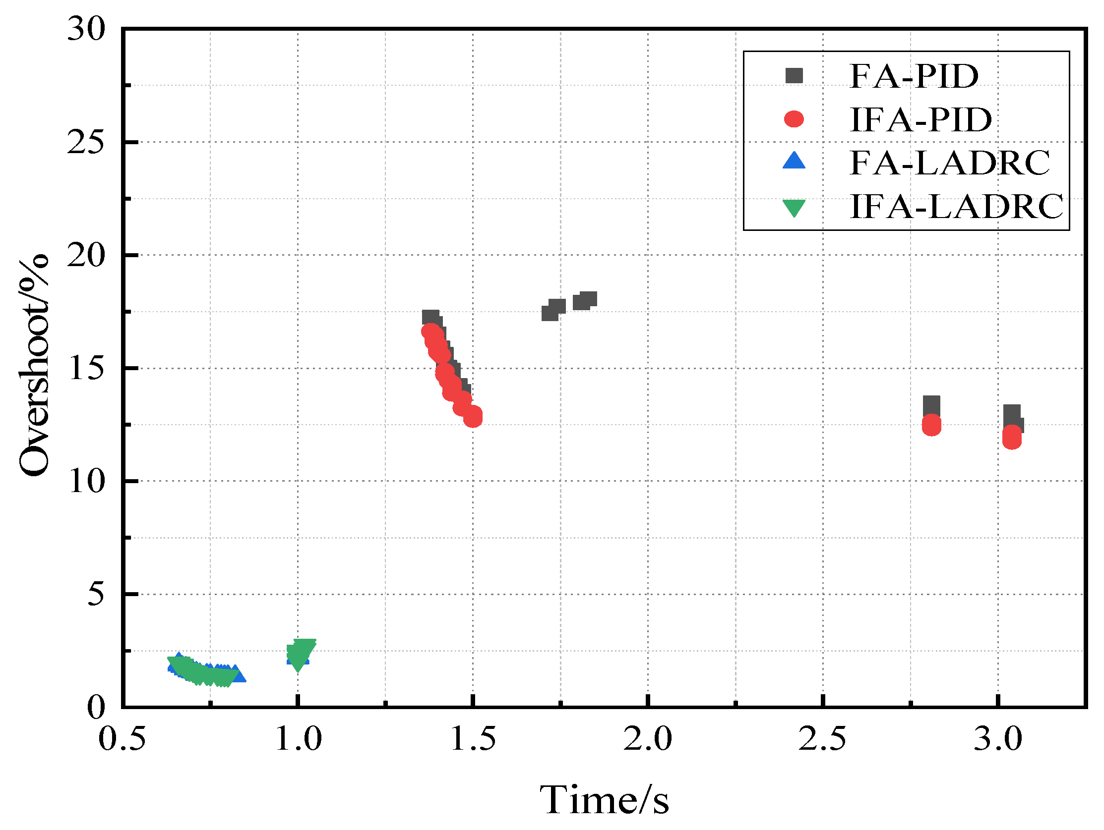
As can be seen from Figure 14, the regulation time and overshoot of IFA-LADRC and FA-ADRC control methods are smaller than the IFA-PID and FA-PID methods with good step response characteristics, which shows that the effect of using the LADRC controller method is very good with a fast response as well as strong anti-interference ability.
In summary, among the four control schemes, the LADRC scheme based on the IFA has a better set value tracking capability, stronger antidisturbance capability, and robustness in the SOFC control system compared with the FA and conventional PID control.
5. Conclusions
In this paper, an IFA-LADRC scheme was designed for offshore wind power SOFC systems, and the IFA based on inertia weights was used to search the optimal controller parameters. To verify the feasibility and correctness of the above methods, a PID control scheme was established for comparison with the LADRC control scheme. In the given value tracking experiments, the overshoots of the four control schemes IFA-LADRC, FA-LADRC, IFA-PID, and FA-PID are 1.95%, 1.78%, 14.13%, and 15.41%, respectively. It can be seen that the overshoots of the system using LADRC are smaller, where the overshoot of the system using the FA-LADRC method is 13.6% less than that using the FA-PID method, and the overshoot of the system using IFA-LADRC method is 12.2% less than that of the system using IFA-PID method. By increasing the voltage perturbation, it can be seen that when T = 100 s, the voltage increases by 7.8%, and at this time, the overshoot of the system using LADRC is reduced by about 5.7% compared to that of the system using PID controller. That is, the LADRC using the improved firefly algorithm is more effective than the PID controller control. In addition, the robustness of the proposed method was verified by Monte Carlo experiments. An offshore wind power hydrogen production system is very complex, and the control problem of the fuel cell can be improved by using an optimization algorithm to improve the controller but also by using a deep learning method to build an SOFC neural network model to improve the control accuracy.
Moreover, there are many studies on electrothermal hydrogen energy management for offshore wind power systems, which is also a topic that can be further investigated. However, this paper is discussed from the simulation point of view, and no actual experiments have been performed. Since the simulation results are good, they can be applied within the actual system in the next step.
Author Contributions
Conceptualization, Z.P. and J.L. (Jing Liu); methodology, Z.P., J.L. (Jia Liu), Z.Q. and J.L. (Jing Liu); validation, Z.P. and X.N.; formal analysis, L.H. and Z.Q.; investigation, J.L. (Jia Liu); resources, J.L. (Jia Liu); data curation, X.N. and Z.Q.; writing—original draft preparation, Z.P. and J.L. (Jia Liu); writing—review and editing, J.L. (Jing Liu); visualization, X.N. and Z.Q.; supervision, J.L. (Jia Liu). All authors have read and agreed to the published version of the manuscript.
Funding
This research was funded by Technology Project of Shanghai Investigation, Design & Research Institute, grant number 2021FD(8)-011.
Institutional Review Board Statement
Not applicable.
Informed Consent Statement
Not applicable.
Data Availability Statement
The data of this work is available by contacting the corresponding author.
Conflicts of Interest
The authors declare no conflict of interest.
References
- Yan, Y.; Zhang, H.; Long, Y.; Wang, Y.-F.; Liang, Y.-T.; Song, X.; James, J. Multi-objective design optimization of combined cooling, heating and power system for cruise ship application. J. Clean. Prod. 2019, 233, 264–279. [Google Scholar] [CrossRef]
- Lucas, T.R.; Ferreira, A.F.; Pereira, R.B.S.; Alves, M. Hydrogen production from the Wind Float Atlantic offshore wind farm: A techno-economic analysis. Appl. Energy 2022, 310, 118481. [Google Scholar] [CrossRef]
- Kaiser, S.; Siems, F.; Mostert, C.; Bringezu, S. Environmental and Economic Performance of CO2-Based Methanol Production Using Long-Distance Transport for H2 in Combination with CO2 Point Sources: A Case Study for Germany. Energies 2022, 15, 2507. [Google Scholar] [CrossRef]
- Lin, H.; Wu, Q.; Chen, X.; Yang, X.; Guo, X.; Lv, J.; Lu, T.; Song, S.; McElroy, M. Economic and technological feasibility of using power-to-hydrogen technology under higher wind penetration in China. Renew. Energy 2021, 173, 569–580. [Google Scholar] [CrossRef]
- Luo, Z.; Wang, X.; Wen, H.; Pei, A. Hydrogen production from offshore wind power in South China. Int. J. Hydrog. Energy 2022, 47, 24558–24568. [Google Scholar] [CrossRef]
- Kuterbekov, K.A.; Nikonov, A.V.; Bekmyrza, K.Z.; Pavzderin, N.B.; Kabyshev, A.M.; Kubenova, M.M.; Kabdrakhimova, G.D.; Aidarbekov, N. Classification of Solid Oxide Fuel Cells. Nanomaterials 2022, 12, 1059. [Google Scholar] [CrossRef]
- Singh, M.; Zappa, D.; Comini, E. Solid oxide fuel cell: Decade of progress, future perspectives and challenges. Int. J. Hydrog. 2021, 46, 27643–27674. [Google Scholar] [CrossRef]
- Beigzadeh, M.; Pourfayaz, F.; Ghazvini, M.; Ahmadi, M. Energy and exergy analyses of solid oxide fuel cell-gas turbine hybrid systems fed by different renewable biofuels: A comparative study. J. Clean. Prod. 2021, 280, 124383. [Google Scholar] [CrossRef]
- Liu, Z.; Chen, H.; Peng, L.; Ye, X.-C.; Xu, S.-C.; Zhang, T. Feedforward-decoupled closed-loop fuzzy proportion-integral-derivative control of air supply system of proton exchange membrane fuel cell. Energy 2022, 240, 122490. [Google Scholar] [CrossRef]
- Tyczka, M.; Skarka, W. Optimisation of operational parameters based on simulation numerical model of hydrogen fuel cell stack used for electric car drive. In Transdisciplinary Engineering: Crossing Boundaries; IOS Press: Amsterdam, The Netherlands, 2016; pp. 622–631. [Google Scholar]
- Malik, F.R.; Tieqing, Z.; Kim, Y.B. Temperature and hydrogen flow rate controls of diesel autothermal reformer for 3.6 kW PEM fuel cell system with autoignition delay time analysis. Int. J. Hydrog. 2020, 45, 29345–29355. [Google Scholar] [CrossRef]
- Wu, X.; Wang, J.; Hao, J.; Li, X.I. Control of a solid oxide fuel cell stack based on unmodeled dynamic compensations. Int. J. Hydrog. 2018, 43, 22500–22510. [Google Scholar] [CrossRef]
- Li, H.; Chen, H.; Gao, N.; T-Ahmed, N.A.; Charpentier, J.F.; Benbouzid, M. Ship Dynamic Positioning Control Based on Active Disturbance Rejection Control. J. Mar. Sci. Eng. 2022, 10, 865. [Google Scholar] [CrossRef]
- Song, J.; Su, J.; Hu, Y.; Zhao, M.; Gao, K. Stability and performance comparison analysis for linear active disturbance rejection control–based system. T. I. Meas. Control 2022, 44, 2037–2048. [Google Scholar] [CrossRef]
- Wu, Z.; Shi, G.; Li, D.; Liu, Y.; Chen, Y. Active disturbance rejection control design for high-order integral systems. ISA Trans. 2022, 125, 560–570. [Google Scholar] [CrossRef]
- Chen, X.; Xu, J.; Liu, Q.; Chen, Y.; Wang, X.-D.; Li, W.-B.; Ding, Y.-J.; Wan, Z.-M. Active disturbance rejection control strategy applied to cathode humidity control in PEMFC system. Energy Convers. Manag. 2020, 224, 113389. [Google Scholar] [CrossRef]
- Zhuo, S.; Xu, L.; Huang, F.-Y.; Gaillard, A.; Paire, D.; Gao, F. Robust adaptive control of interleaved boost converter for fuel cell application. IEEE T Ind. Appl. 2021, 57, 6603–6610. [Google Scholar] [CrossRef]
- Dos-Santos-Coelho, L.; Mariani, V.-C. Improved firefly algorithm approach applied to chiller loading for energy conservation. Energy Build. 2013, 59, 273–278. [Google Scholar] [CrossRef]
- Hao, X.; Salhi, I.; Laghrouche, S.; Ait-Amirat, Y.; Djerdir, A. Backstepping Supertwisting Control of Four-Phase Interleaved Boost Converter for PEM Fuel Cell. IEEE Trans. Power Electron. 2022, 37, 7858–7870. [Google Scholar] [CrossRef]
- Kumar, R.; Talukdar, F.A.; Rajan, A.; Devi, A.; Raja, R. Parameter optimization of 5.5 GHz low noise amplifier using multi-objective Firefly Algorithm. Microsyst. Technol. 2020, 26, 3289–3297. [Google Scholar] [CrossRef]
- Eyni, E.; Stanko, M.; Schümann, H.; Qureshi, A.H. Dynamic Process Modeling of Topside Systems for Evaluating Power Consumption and Possibilities of Using Wind Power. Energies 2022, 15, 9482. [Google Scholar] [CrossRef]
- Jang, D.; Kim, K.; Kim, K.H.; Kang, S. Techno-economic analysis and Monte Carlo simulation for green hydrogen production using offshore wind power plant. Energy Convers. Manag. 2022, 263, 115695. [Google Scholar] [CrossRef]
- Yang, B.; Li, Y.; Li, J.; Shu, H.; Zhao, X.; Ren, Y.; Li, Q. Comprehensive summary of solid oxide fuel cell control: A state-of-the-art review. Prot. Control Mod. Power Syst. 2022, 7, 36. [Google Scholar] [CrossRef]
- Buttler, A.; Spliethoff, H. Current status of water electrolysis for energy storage, grid balancing and sector coupling via power-to-gas and power-to-liquids: A review. Renew. Energy 2018, 82, 2440–2454. [Google Scholar] [CrossRef]
- Qin, X.; Cao, J.; Geng, G.; Li, Y.; Zheng, Y.; Zhang, W.; Yu, B. Solid oxide fuel cell system for automobiles. Int. J. Green Energy 2022, 2022, 1–10. [Google Scholar] [CrossRef]
- Zhang, L.; Tang, W.; Wang, F.; Xie, C.; Zhou, W.; Xie, H. Optimization and Control for Solid Oxide Fuel Cell System Hybrid DC Microgrids From the Perspective of High Efficiency, Thermal Safety, and Transient Response. Front. Energy Res. 2023, 16648714, 953082. [Google Scholar] [CrossRef]
- Padulles, J.; Ault, G.W.; McDonald, J.R. An integrated SOFC plant dynamic model for power systems simulation. J. Power Sources 2000, 86, 495–500. [Google Scholar] [CrossRef]
- Ni, M.; Leung, M.K.H.; Leung, D.Y.C. Parametric study of solid oxide fuel cell performance. Energy Convers. Manag. 2007, 48, 1525–1535. [Google Scholar]
- Kumar PG, A.; Jeyanthy, P.A.; Devaraj, D. Hybrid multi-objective method based on ant colony optimization and firefly algorithm for renewable energy sources. Sustain. Comput. Infor. 2022, 36, 100810. [Google Scholar] [CrossRef]
- Flori, A.; Oulhadj, H.; Siarry, P. QUAntum Particle Swarm Optimization: An auto-adaptive PSO for local and global optimization. Comput. Optim. Appl. 2022, 82, 525–559. [Google Scholar] [CrossRef]
- Behera, M.; Sarangi, A.; Mishra, D.; Mallick, P.K.; Shafi, J.; Srinivasu, P.N.; Ljaz, M.F. Automatic Data Clustering by Hybrid Enhanced Firefly and Particle Swarm Optimization Algorithms. Mathematics 2022, 10, 3532. [Google Scholar] [CrossRef]
- Qin, Y.; Sun, L.; Hua, Q.; Liu, P. A fuzzy adaptive PID controller design for fuel cell power plant. Sustainability 2018, 10, 2438. [Google Scholar] [CrossRef] [Green Version]
Figure 1.
Block diagram of offshore wind SOFC system structure.
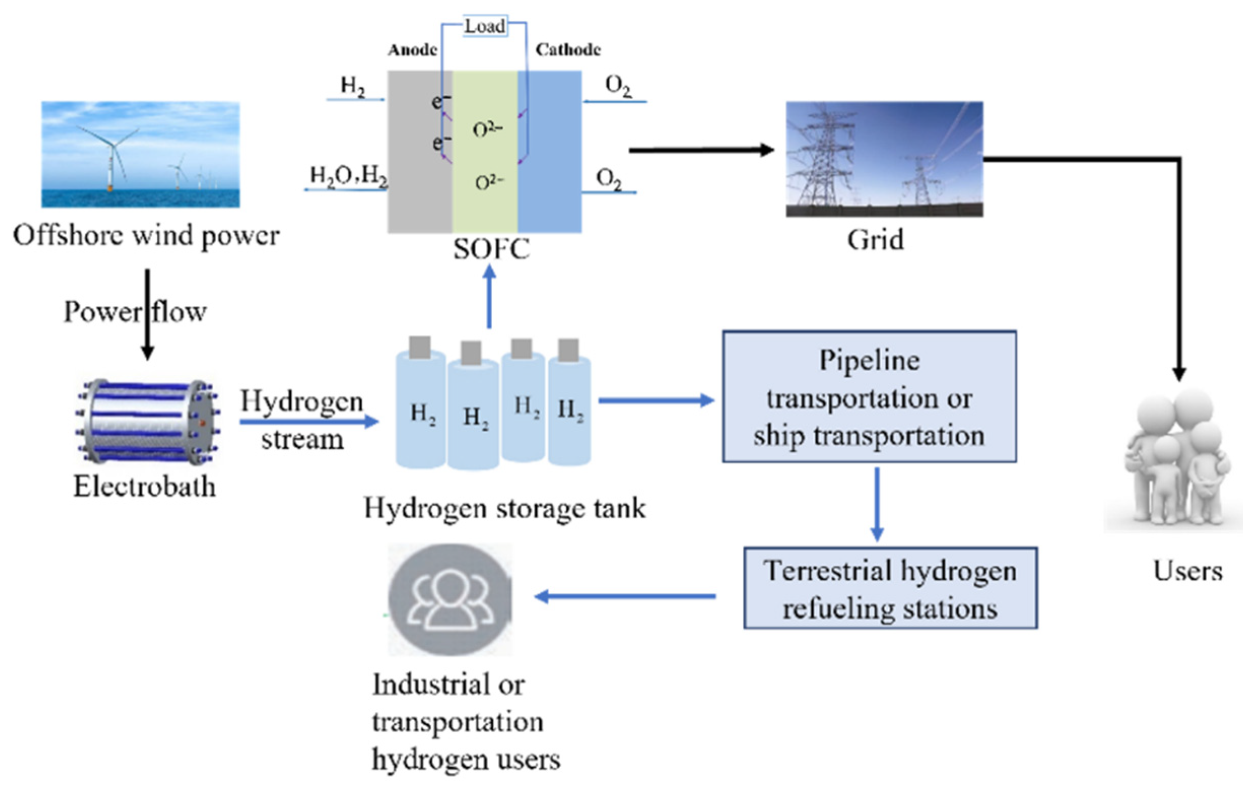
Figure 2.
Partial model block diagram of SOFC system.
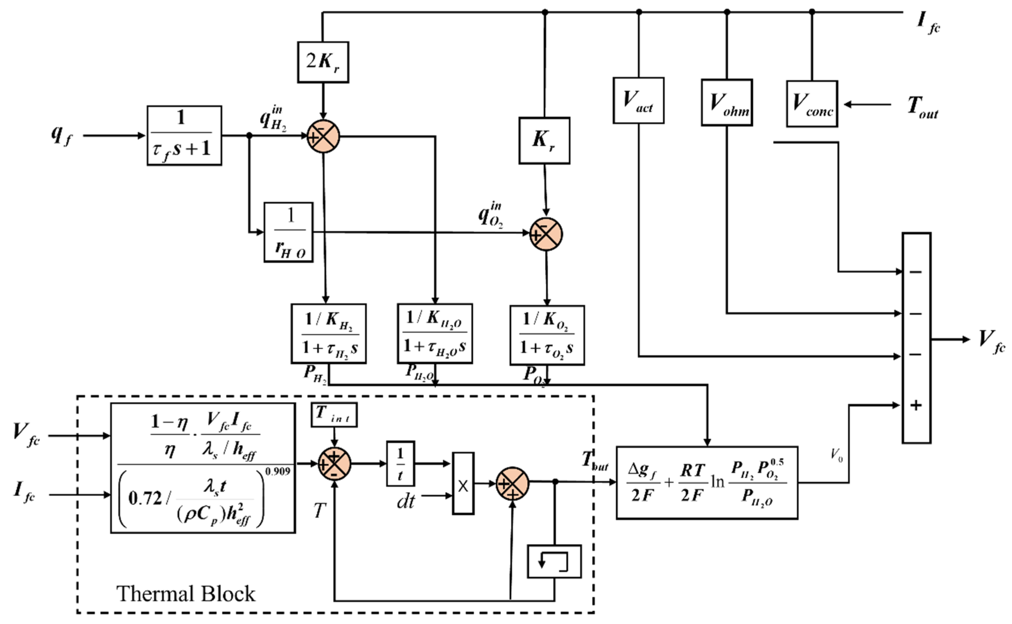
Figure 3.
Block diagram of second-order LADRC controller structure.
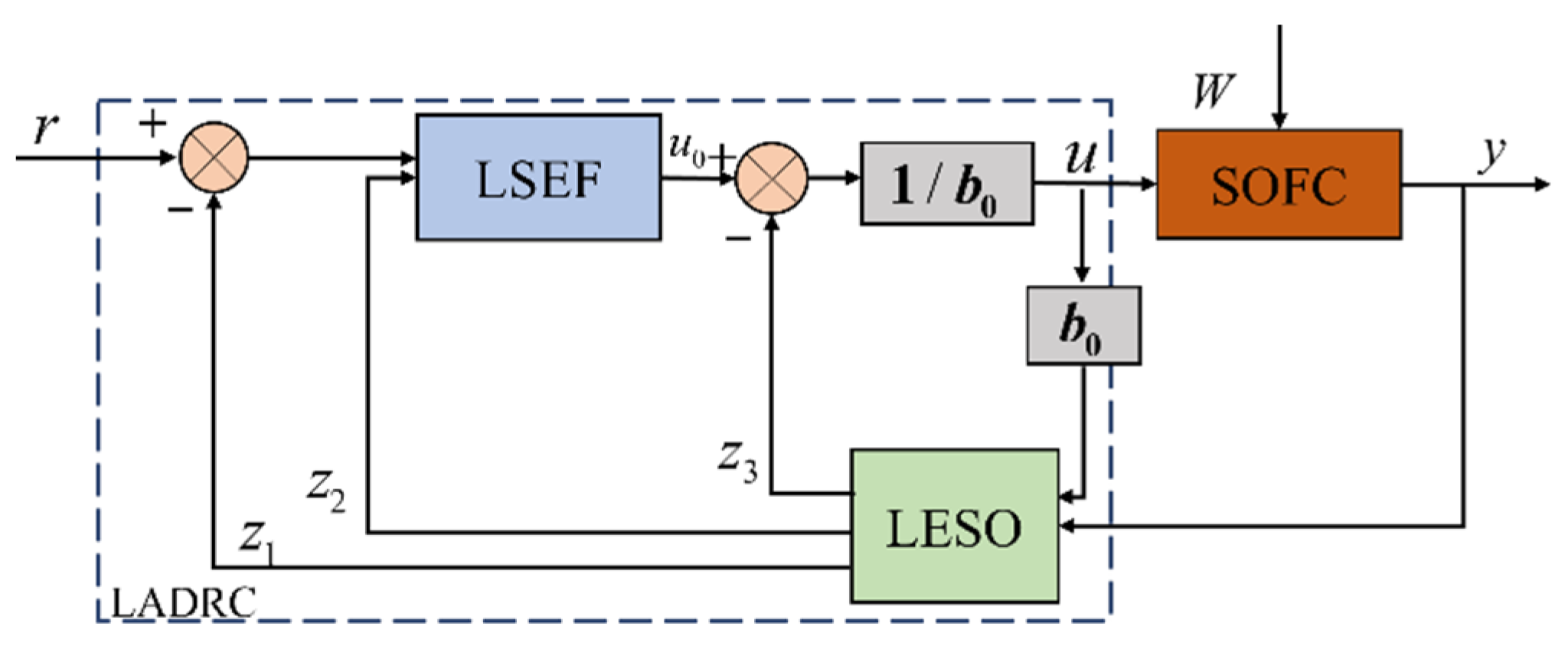
Figure 4.
Flow chart of the IFA-LADRC control scheme.
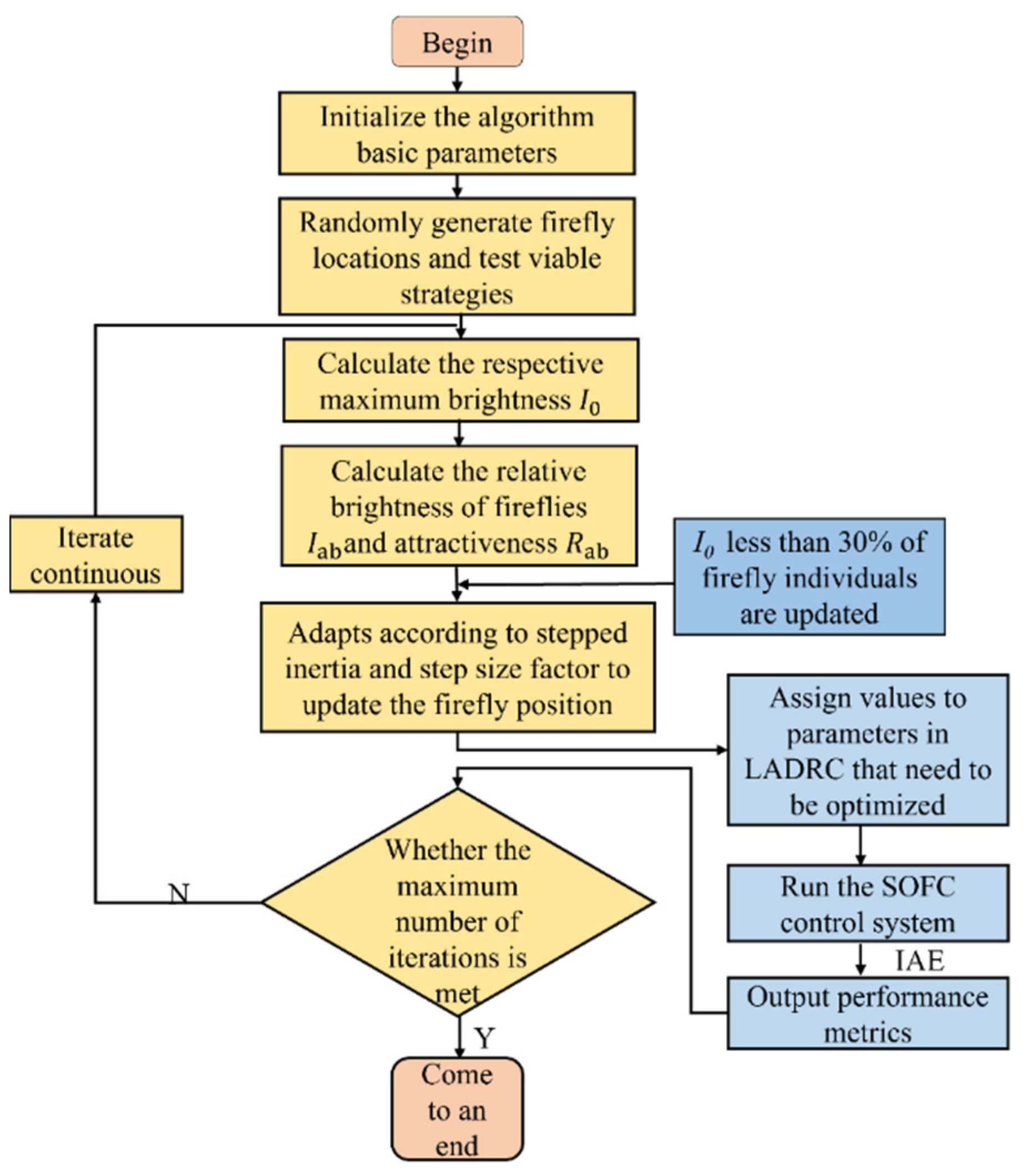
Figure 5.
LADRC structure diagram of SOFC system.
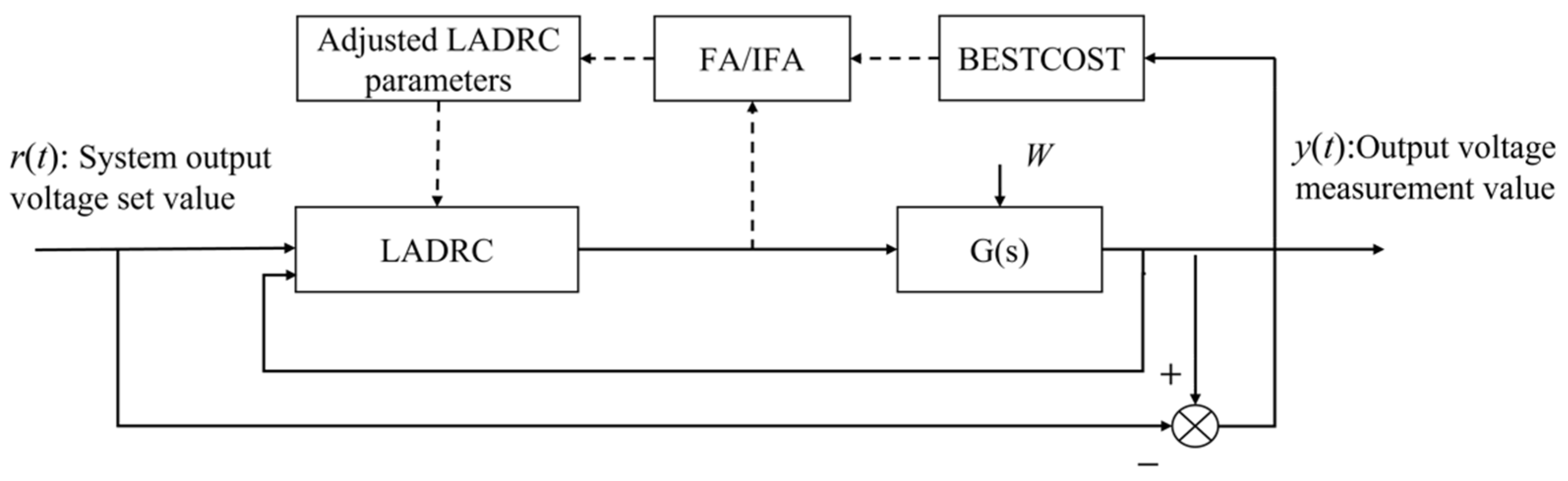
Figure 6.
Convergence curve.
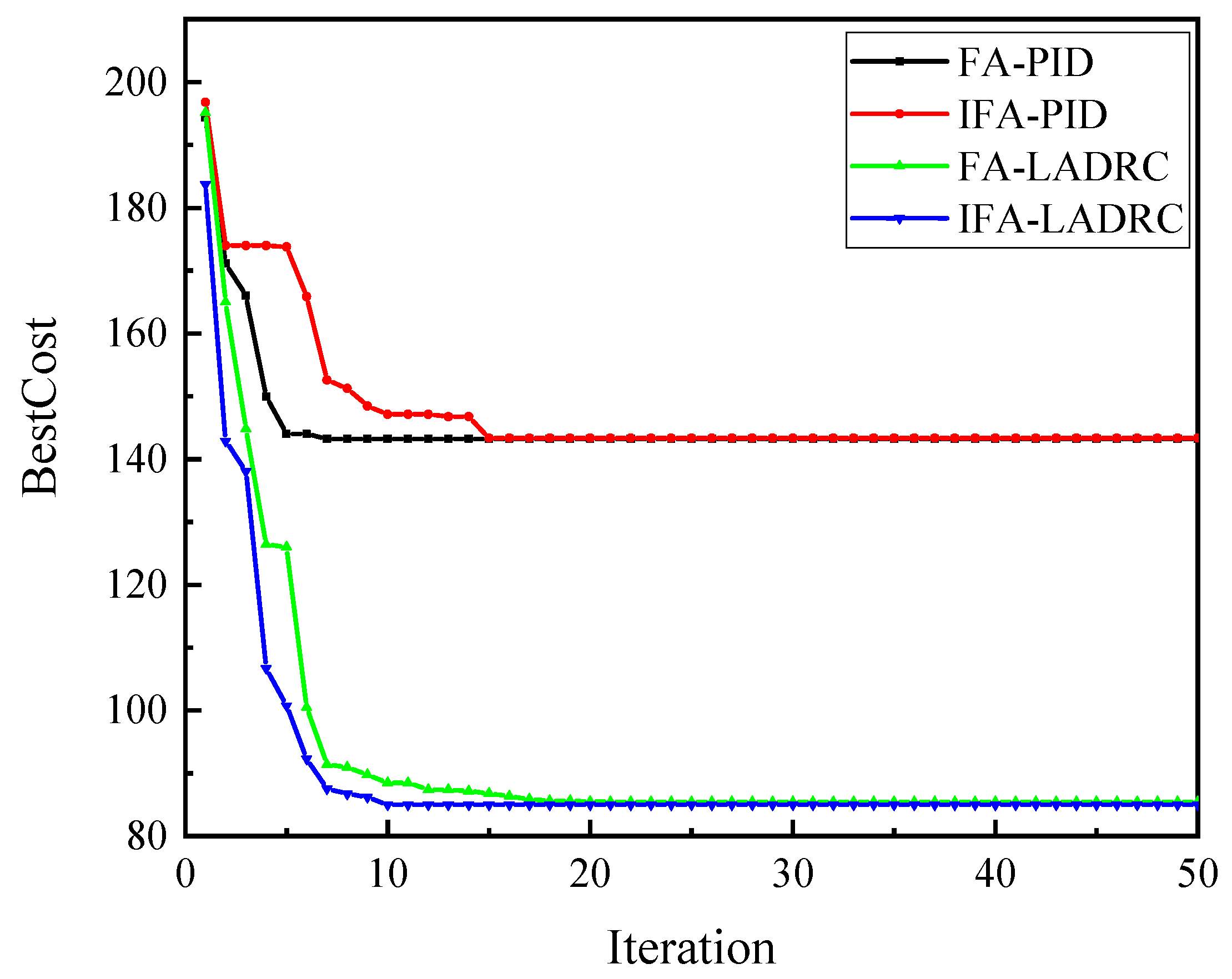
Figure 7.
Step response curve.
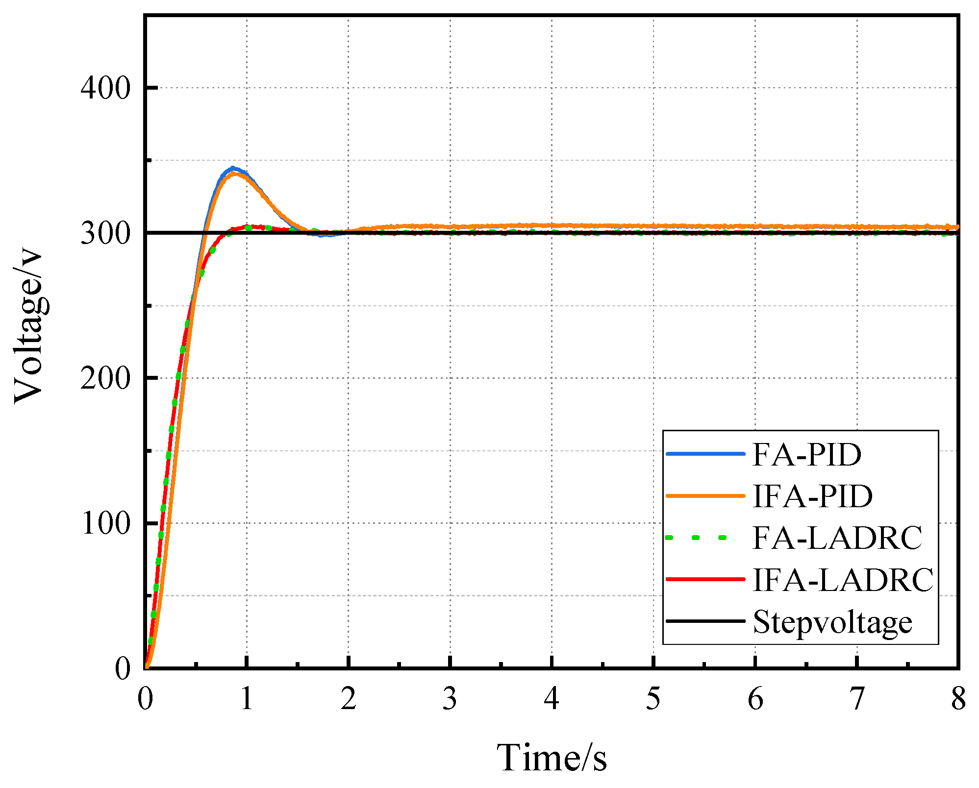
Figure 8.
Voltage rise and fall response curve. (a) PID controller control. (b) LADRC controller control.
Figure 8.
Voltage rise and fall response curve. (a) PID controller control. (b) LADRC controller control.
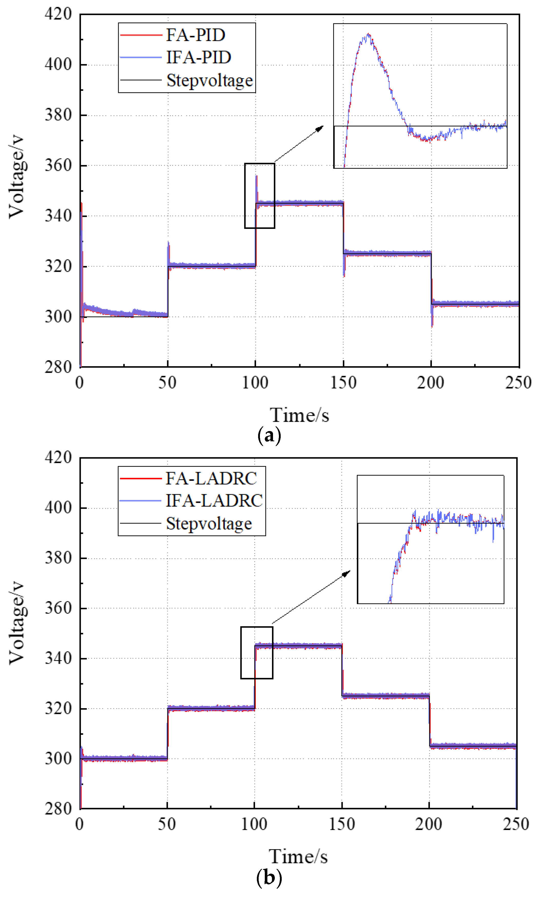
Figure 9.
Magnification of the stepup and stepdown response curves of two controllers. (a) PID controller boost response curves. (b) PID controller buck response curves. (c) LADRC controller boost response curves. (d) LADRC controller buck response curves.
Figure 9.
Magnification of the stepup and stepdown response curves of two controllers. (a) PID controller boost response curves. (b) PID controller buck response curves. (c) LADRC controller boost response curves. (d) LADRC controller buck response curves.

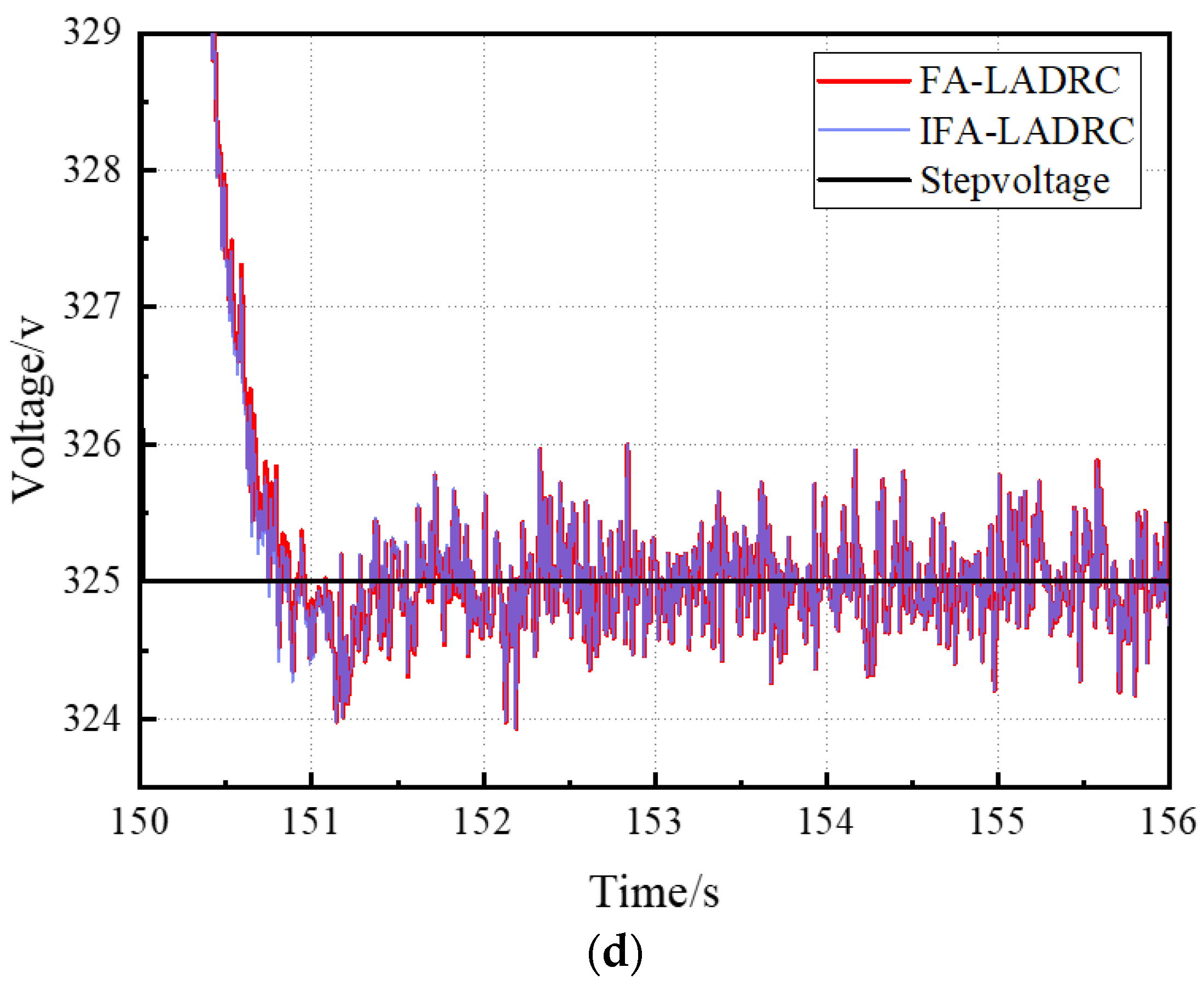
Figure 10.
Voltage rise and fall response curves under different controllers.
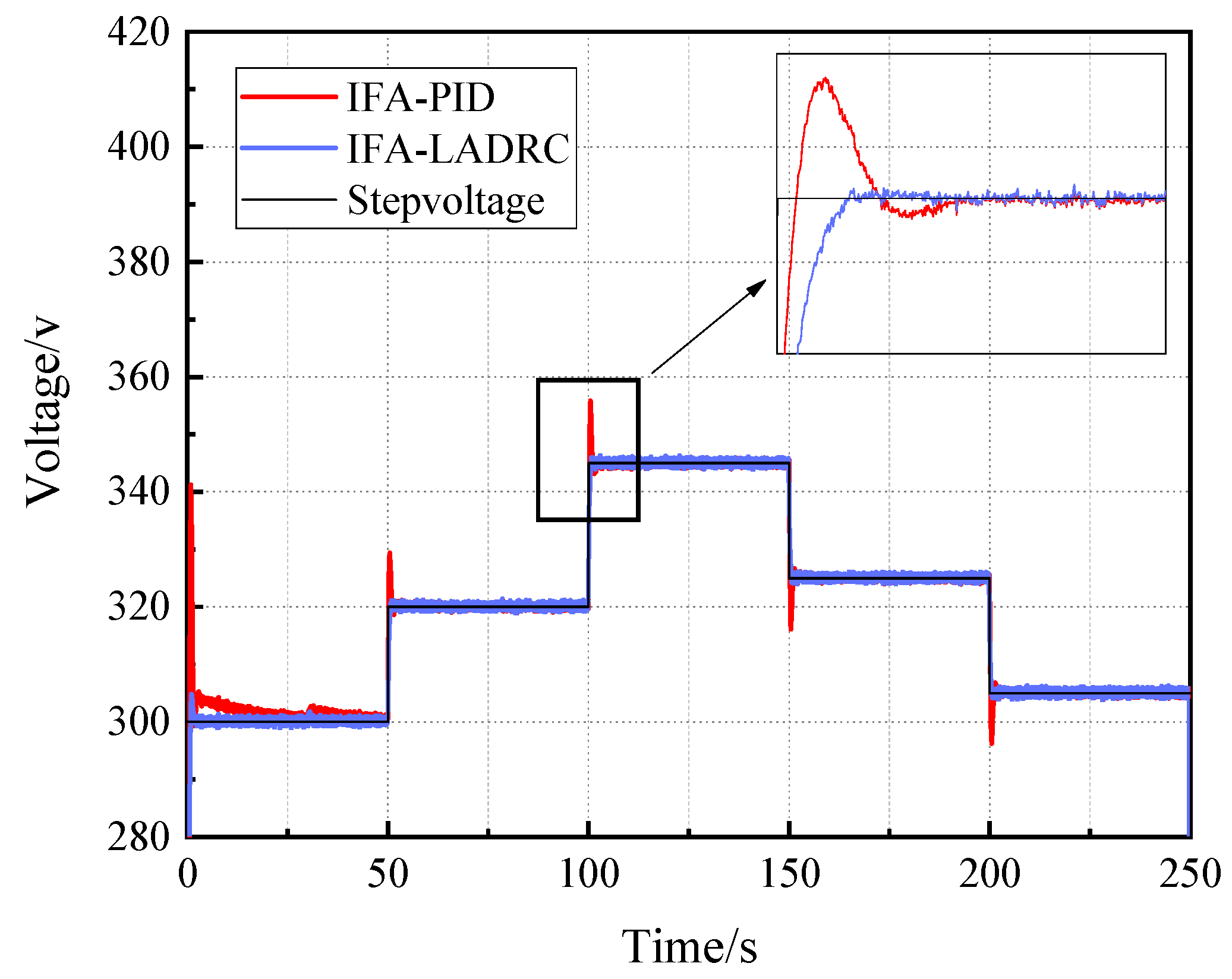
Figure 11.
Voltage rise and fall response curves under different controllers. (a) Comparison of PID and LADRC boost voltage. (b) Comparison of PID and LADRC stepdown.
Figure 11.
Voltage rise and fall response curves under different controllers. (a) Comparison of PID and LADRC boost voltage. (b) Comparison of PID and LADRC stepdown.
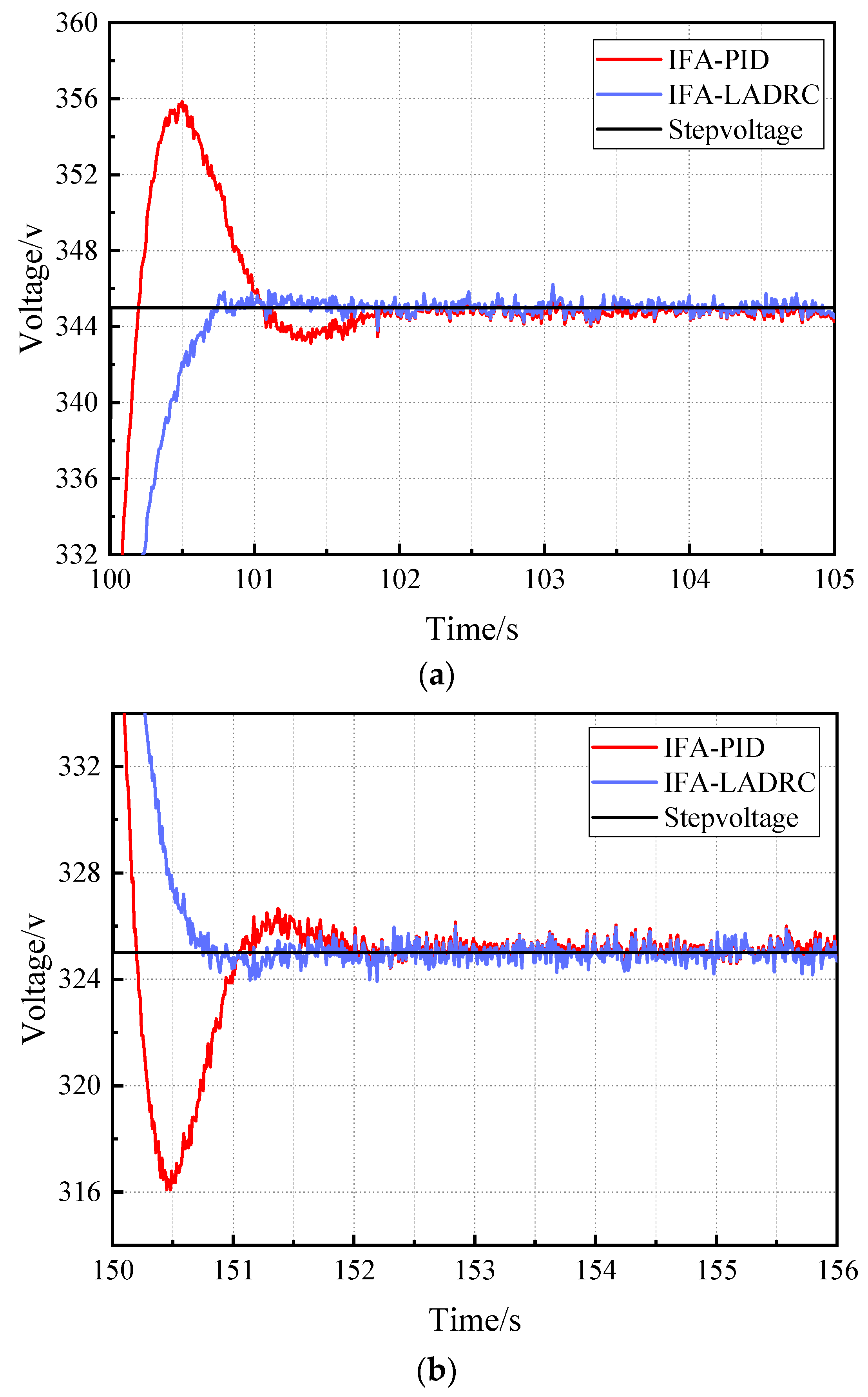
Figure 12.
Monte Carlo experiment of (a) FA-PID and (b) IFA-PID control methods, wherein the lines in different colors denote system voltage outputs after the addition of a random disturbance within [20%, −20%].
Figure 12.
Monte Carlo experiment of (a) FA-PID and (b) IFA-PID control methods, wherein the lines in different colors denote system voltage outputs after the addition of a random disturbance within [20%, −20%].
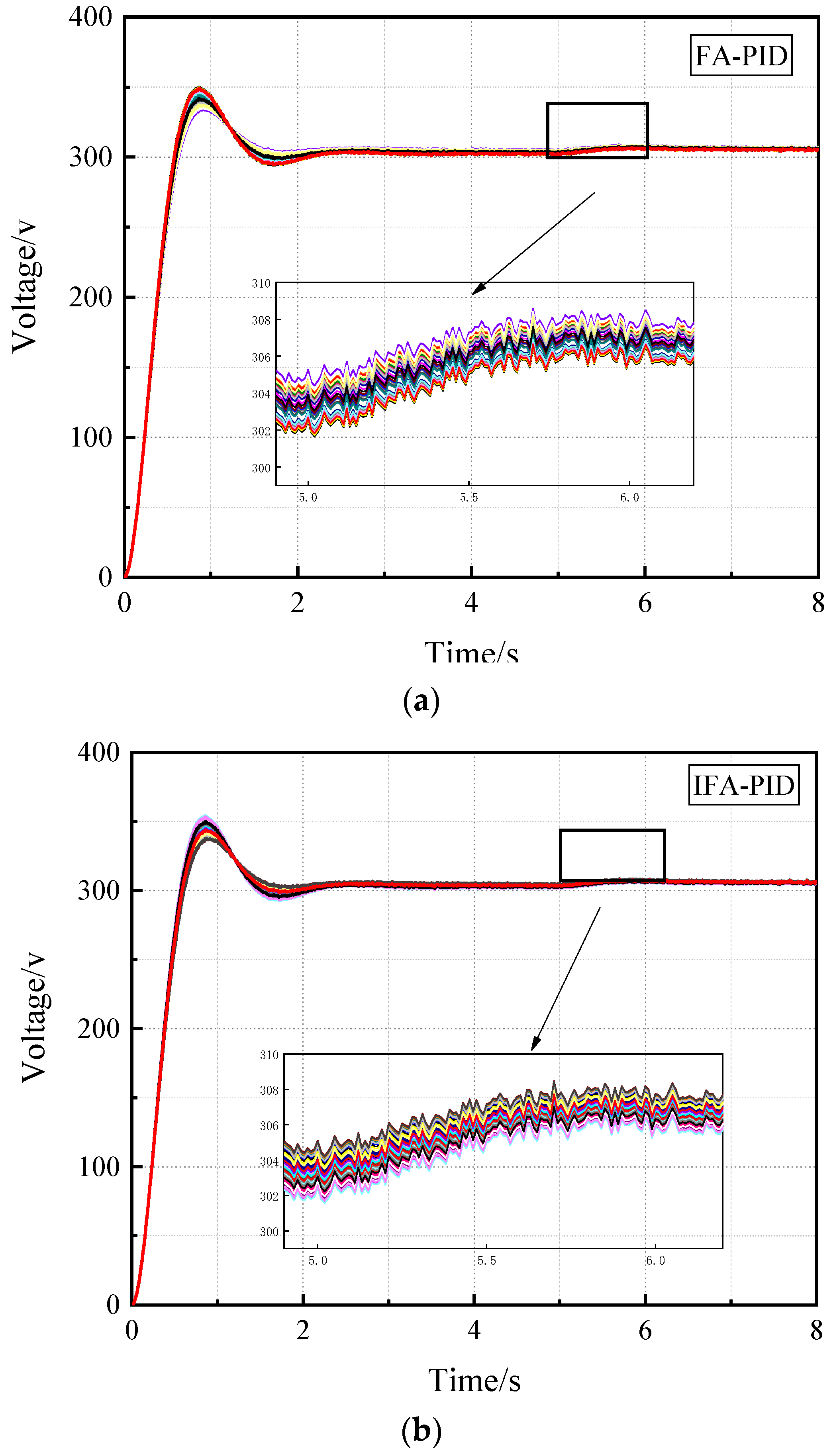
Figure 13.
Monte Carlo experiment of (a) FA-LADRC and (b) IFA-LADRC control methods, wherein the lines in different colors denote system voltage outputs after the addition of a random disturbance within [20%, −20%] (the same below).
Figure 13.
Monte Carlo experiment of (a) FA-LADRC and (b) IFA-LADRC control methods, wherein the lines in different colors denote system voltage outputs after the addition of a random disturbance within [20%, −20%] (the same below).
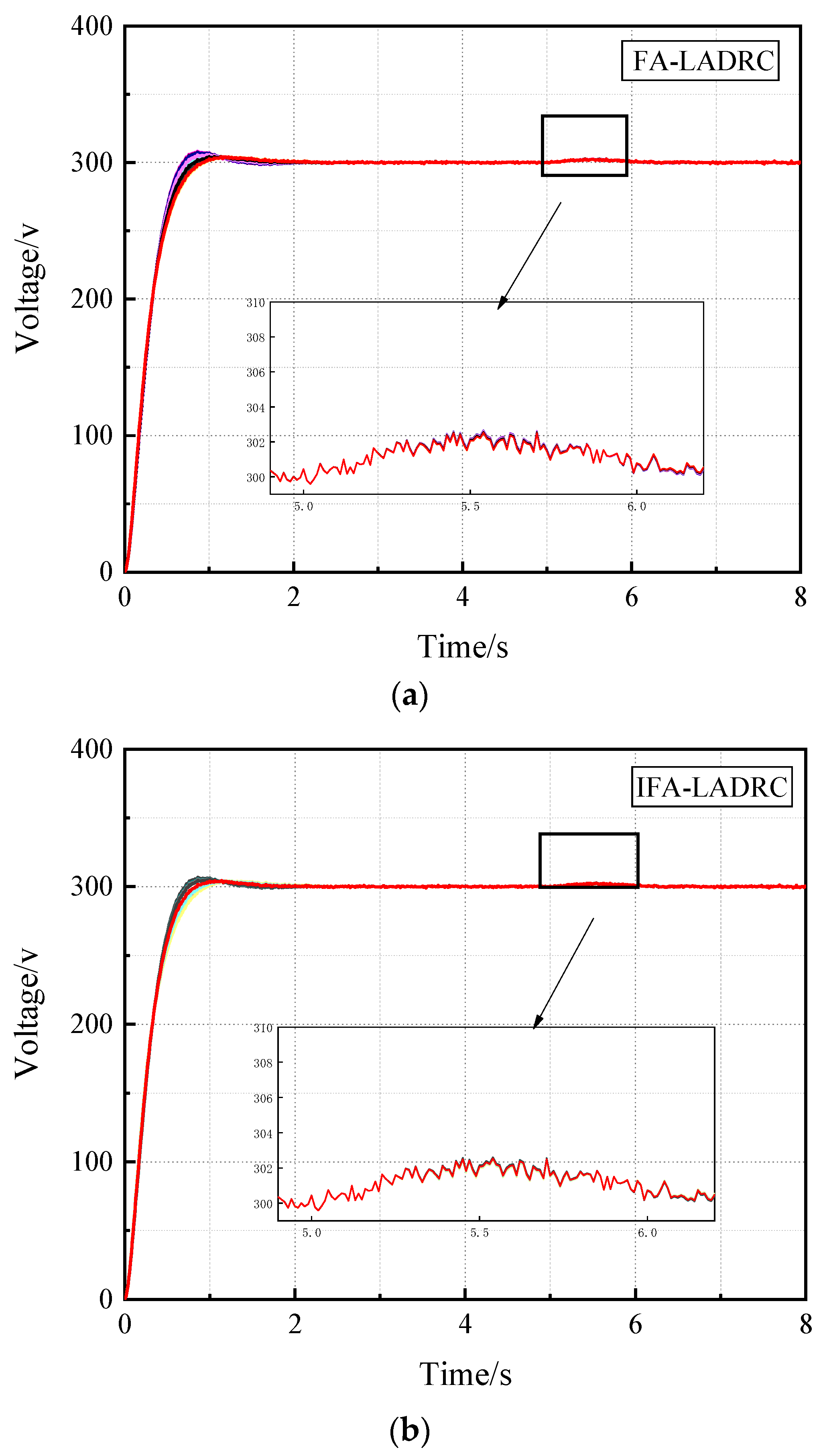
Figure 14.
Performance indicators of four control methods under Monte Carlo simulation.

Table 1.
Meaning of involved SOFC system parameters.
| Symbol | Parameter |
|---|---|
| Valve molar constant for hydrogen | |
| Valve molar constant for steam | |
| Valve molar constant for oxygen | |
| Reaction constant | |
| Response time for steam flow | |
| Response time for oxygen flow | |
| Response time for hydrogen flow | |
| Fuel processor response time | |
| Initial temperature | |
| Constant temperature | |
| Thermal conductivity | |
| Thickness |
Table 2.
Values of involved SOFC system parameters.
| Symbol | Value |
|---|---|
| 0.843 mol/(s atm) | |
| 0.281 mol/(s atm) | |
| 2.52 mol/(s atm) | |
| 0.993 × 10⁻³ mol/(s A) | |
| 78.3 s | |
| 2.91 s | |
| 26.1 s | |
| 5 s | |
| 1273 K | |
| 973 K | |
| 2 W/(m K) | |
| 10−3 m |
Table 3.
Optimization parameters under PID controller and error integration index.
| Kp | Ki | Kd | BestCost | |
|---|---|---|---|---|
| IFA-PID | 7.500 | 0.500 | 1.8154 | 143.3511 |
| FA-PID | 7.500 | 0.500 | 1.7522 | 143.2294 |
Table 4.
Optimization parameters under LADRC and error integration index.
| ω0 | ωc | b0 | BestCost | |
|---|---|---|---|---|
| IFA-ADRC | 7.500 | 7.500 | 2.5788 | 85.0153 |
| FA-ADRC | 7.4986 | 7.4906 | 2.5221 | 85.4307 |
Disclaimer/Publisher’s Note: The statements, opinions and data contained in all publications are solely those of the individual author(s) and contributor(s) and not of MDPI and/or the editor(s). MDPI and/or the editor(s) disclaim responsibility for any injury to people or property resulting from any ideas, methods, instructions or products referred to in the content. |
© 2023 by the authors. Licensee MDPI, Basel, Switzerland. This article is an open access article distributed under the terms and conditions of the Creative Commons Attribution (CC BY) license (https://creativecommons.org/licenses/by/4.0/).
Share and Cite
MDPI and ACS Style
Pan, Z.; Liu, J.; Liu, J.; Ning, X.; Qin, Z.; He, L. Active Disturbance Rejection Optimization Control for SOFCs in Offshore Wind Power. Appl. Sci. 2023, 13, 3364. https://doi.org/10.3390/app13053364
AMA Style
Pan Z, Liu J, Liu J, Ning X, Qin Z, He L. Active Disturbance Rejection Optimization Control for SOFCs in Offshore Wind Power. Applied Sciences. 2023; 13(5):3364. https://doi.org/10.3390/app13053364
Chicago/Turabian StylePan, Zhixuan, Jia Liu, Jing Liu, Xiaoge Ning, Zheng Qin, and Lulu He. 2023. "Active Disturbance Rejection Optimization Control for SOFCs in Offshore Wind Power" Applied Sciences 13, no. 5: 3364. https://doi.org/10.3390/app13053364
Note that from the first issue of 2016, this journal uses article numbers instead of page numbers. See further details here.