Article

Improvement of Braking Response Performance of Fault-Tolerant Dual Winding Motor for Integrated Brake System Using Winding Switching

1
School of Railway Operation and Control, Dongyang University, Punggi, Yeongju 36040, Republic of Korea
2
Department of Electrical Engineering, Honam University, 417 Eodeung-daero, Gwangju 62399, Republic of Korea
*
Author to whom correspondence should be addressed.
Appl. Sci. 2023, 13(6), 3442; https://doi.org/10.3390/app13063442
Submission received: 6 February 2023 / Revised: 5 March 2023 / Accepted: 6 March 2023 / Published: 8 March 2023
(This article belongs to the Section Electrical, Electronics and Communications Engineering)

Abstract

:
Unlike the winding structure of existing three-phase single winding motors, the winding structure of the dual winding motor (DWM) contains a master part and two slave parts. Thus, when the master part fails, it can be driven using the remaining slave part. It is applicable to various electric parts driving the integrated electric brake (IEB) system; thereby securing the high reliability of vehicle parts. However, in the existing DWM, there is an overheating problem owing to the increase in current because it operates with half the motor during the faulty mode. Therefore, a compensation method for the increase in current in a faulty mode was employed by increasing the stacking length of the DWM. However, although it solves the overheating problem of the DWM in the faulty mode, the motor output performance and braking performance of the IEB system are degraded in the normal mode because of the change in the motor control parameters. Thus, in this paper, we propose a DWM with winding switching (WS) to simultaneously solve the DWM overheating problem in the faulty mode and the DWM’s performance degradation problem in the normal mode. The output performance of the DWM with an increased stack length and the previously developed base model are compared to verify the performance of the proposed DWM with WS. As a result of the comparison, unlike the DWM with an increased stack length, in which the maximum speed is reduced by 20.5% compared to the existing base model during quick braking in the normal mode, the proposed DWM with WS has no performance degradation. In other words, it is confirmed that the proposed DWM with WS effectively solves the overheating problem during faulty mode, while simultaneously solving the performance degradation problem of the IEB system during the normal mode.

1. Introduction

Recently, with the development of technology and popularization of electric vehicles (EVs), interest in autonomous vehicles has increased [1,2,3,4,5,6]. Autonomous vehicle technology has many advantages, such as reducing traffic accidents, establishing a more efficient transportation system, greatly reducing social costs caused by traffic accidents or traffic congestion, and reducing car-related crime; thus, autonomous vehicles can become the mainstream transportation method in the future. Accordingly, several studies have been conducted on autonomous vehicles. However, accidents involving autonomous vehicles occur frequently because the technology is still developing [2,3]. For autonomous vehicles, there is no driver intervention; therefore, it is necessary to secure vehicle safety technology in case of an emergency. Accordingly, the importance of fail safety and redundant systems in automobiles is increasing.
Recently, various redundant systems that use two motors have been studied to ensure the safety of autonomous vehicles [7,8,9]. Studies on redundant systems include a redundant steering system driven by connecting two motors to one axis [7]; a redundant driving system of an EV containing two motors, two batteries, and a dual inverter [8]; and two motors and redundant robot systems comprising two gearboxes [9]. A system using a DWM with one motor was developed [10,11,12]. DWMs are applied in various fields, such as electronic brake systems [10], aerospace fields [11], and electric power steering systems [12].
An advantage is that a redundant system can be implemented with one motor by applying a double-winding structure to one motor. However, in the case of a DWM that separates one motor into two, additional overheating problems may occur owing to increased current consumption because half of the motor must be driven in case of a failure. To solve this problem, a compensation method for the increase in current consumption in the faulty mode has been proposed, which involves increasing the stacking length of the DWM [13]. However, this has a problem in that the output power of the motor and the response performance of the IEB system deteriorate under the same current usage condition because resistance and BEMF increase as the stacking length increases.
To simultaneously solve the overheating problem in the faulty mode and the output performance degradation in the normal mode of the DWM, it is necessary to investigate a new alternative that only changes the winding connection state for each operation mode without changing the motor design specifications. As a representative method of changing the winding connection state for each operation mode without changing the motor design, there is a winding switching (WS) [14,15,16,17,18,19,20]. Sin et al. [14,15] proposed a cumulative/differential WS method to obtain a constant power speed range using a three-phase single inverter. Arsalan et al. [16] designed two modes of operation for a PMVM to improve efficiency and wide-speed-range operation using WS. In mode-one, high torque was achieved with the stator winding connected in a wye configuration. In mode-two, a wide speed range was achieved with the stator winding connected in a wye–delta configuration. Muhammad et al. [17,18] proposed a novel winding scheme using WS to generate an additional sub-harmonic magnetomotive force (SH-MMF) component for the brushless operation of a wound-field synchronous machine. Ali and Hwang et al. [19] designed a dual-mode brushless wound rotor synchronous machine (DBL-WRSM) for a high starting torque using WS to achieve a higher starting torque than a conventional brushless wound rotor synchronous machine (BL-WRSM). Lim et al. [20] proposed a design method for a wound field synchronous motor (WFSM) employing a dual-stator winding and winding connection change circuit. Accordingly, WS can be used to change the winding state, which can change the number of parallel circuits or change the delta connection to the Y connection.
In this paper, we propose a DWM with WS to simultaneously solve the overheating problem in the faulty mode and the performance degradation problem of an IEB system in the normal mode. In addition, the winding topology and output performances of the previously developed base model and the DWM with an increased stack length are compared to verify the validity of the proposed DWM with WS.
The main contributions of the paper are as follows.
(1)
The proposed DWM with WS considers both the overheating problem in the faulty mode and the performance degradation problem of IEB system in the normal mode.
(2)
In order to minimize the development cost, the DWM with WS was developed utilizing the previously developed base model.
(3)
The proposed DWM with WS was effectively applied to the IEB system. In addition, the scope of various other DWM-based applications can be expanded.
The remainder of this paper is organized as follows. Section 2 introduces the IEB system and DWM to be applied. Section 3 shows the structure and performance comparison of the conventional DWM and the DWM with an increased stacking length designed to prevent overheating during fault operation. The motor performance and braking response performance of the IEB system were compared. In Section 4, the performances of the proposed DWM and the base model are compared to confirm the validity of the proposed DWM. Finally, section V presents the conclusions of this study.

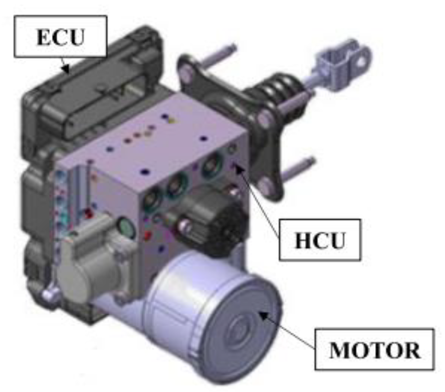
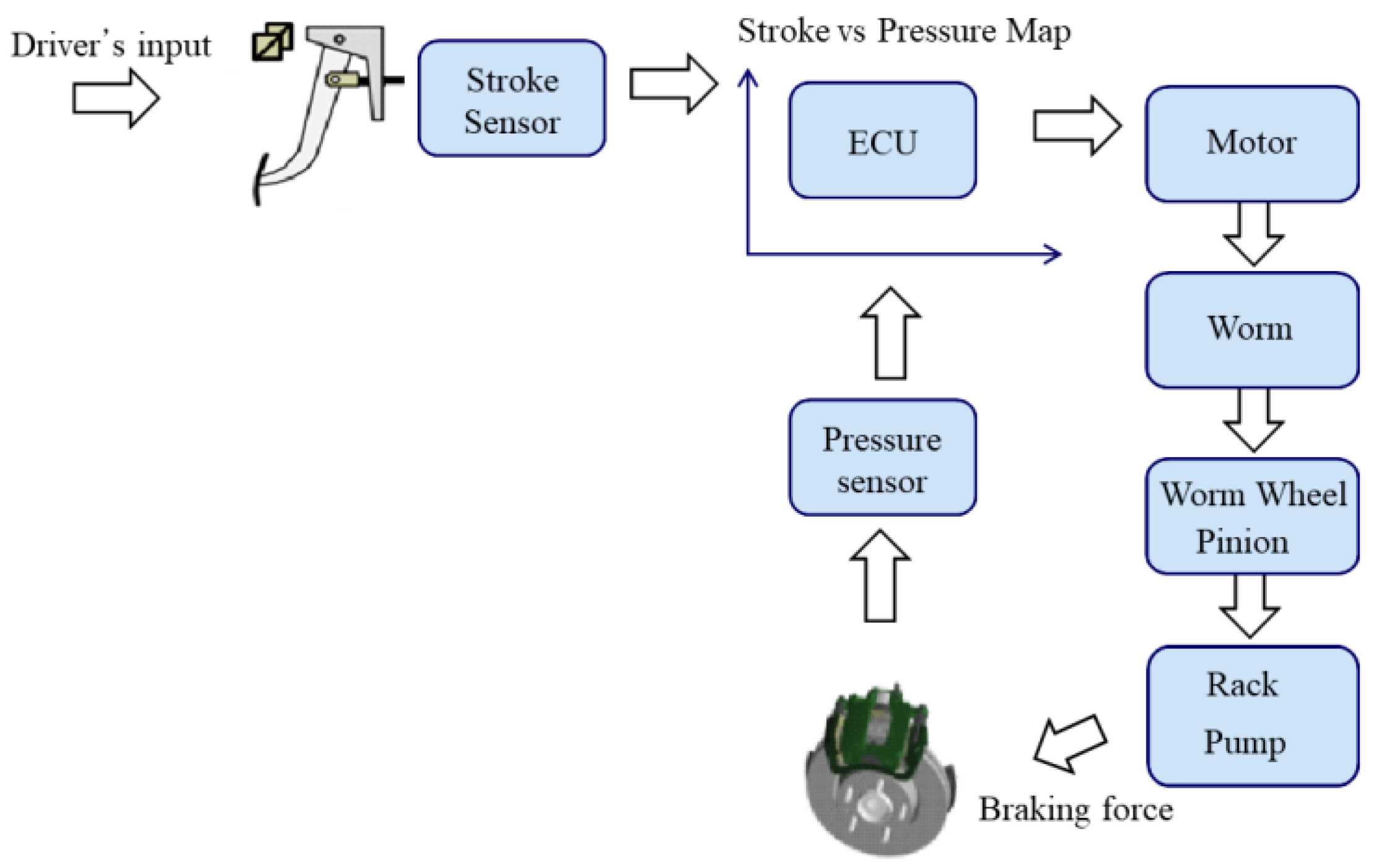
2. Integrated Electric Brake System

The IEB system introduced in this study is a single box, as shown in Figure 1, and consists of a hydraulic control unit (HCU), electronic control unit (ECU), and motor assembly. It replaces the existing hydraulic booster with a motor and integrates the electronic stability control system and ABS module into one box [21,22,23,24].
Figure 2 presents the operating sequence of the electric brake system. The IEB system primarily contains a motor, worm gear, worm wheel, pinion gear assay, rack gear, and a pump. When the driver steps on the pedal and sends a signal to the stroke sensor, the ECU receives the stroke sensor signal and sends the operation signal to the motor. The braking force was transmitted to the vehicle caliper via the gear and pump.
Figure 3 and Figure 4 illustrate the topology and winding arrangement of the base motor used to operate the developed integrated electric brake system. It has an 8-pole 12-slot surface permanent magnet structure, and the winding is composed of four parallel concentrated windings.
The specifications of the base model are listed in Table 1. Maximum power at high speeds is crucial for ensuring rapid braking performance in electric brake systems. The characteristics of the torque constant are also an important design factor for the continuous braking operation of an electric brake system.
If the motor fails, the vehicle cannot brake because the IEB system operates based on the motor. This is a problem that significantly affects driver safety, particularly for autonomous vehicles. Therefore, it is necessary to develop a dual drive system composed of two or more components so that the system can operate even if the motor or inverter fails. The DWM is a representative motor of a dual drive system.
When designing a DWM based on a base model that has already been developed, it is advantageous in terms of price, as it can utilize existing manufacturing tools. In this study, to minimize the development cost, a DWM was implemented by changing only the number of winding series and parallel circuits from the existing developed base model.

3. Dual Winding Motor

If the motor fails, the vehicle cannot brake because the IEB system operates based on the motor. This is a problem that significantly affects driver safety. Therefore, it is necessary to develop a dual-drive system composed of two or more components so that the system can operate even if the motor or inverter fails. The DWM is a representative motor of a dual-drive system.

3.1. Conventional Dual Winding Motor

The conventional DWM has a dual winding structure with a master part and a slave part, as shown in Figure 5; if the master part fails, it operates using only the slave part. This analysis model is a two-parallel structure, and it was implemented simply by changing the number of parallel circuits from the previously developed four-parallel concentrator base model for IEB. As shown in Figure 5, the master part of this analysis model is composed of U1, U2, V1, V2, W1, and W2, and the master part is composed of U3, U4, V3, V4, W3, and W4 [25].
Table 2 compares the specifications for the motor control parameters of the base model and the conventional DWM. Conventional DWM was designed by only changing the series–parallel structure of the base model, and, since the number of parallel circuits was reduced by two times, resistance and inductance were each doubled compared to the base model.
The winding topology of a conventional DWM is illustrated in Figure 6. As described above, when a conventional DWM operates as a master or slave part in the faulty mode, the current uses doubles, causing coil burnout owing to overheating. Accordingly, a DWM with an increased stack length was applied to compensate for the increase in use current during faulty operation.

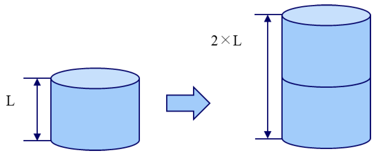
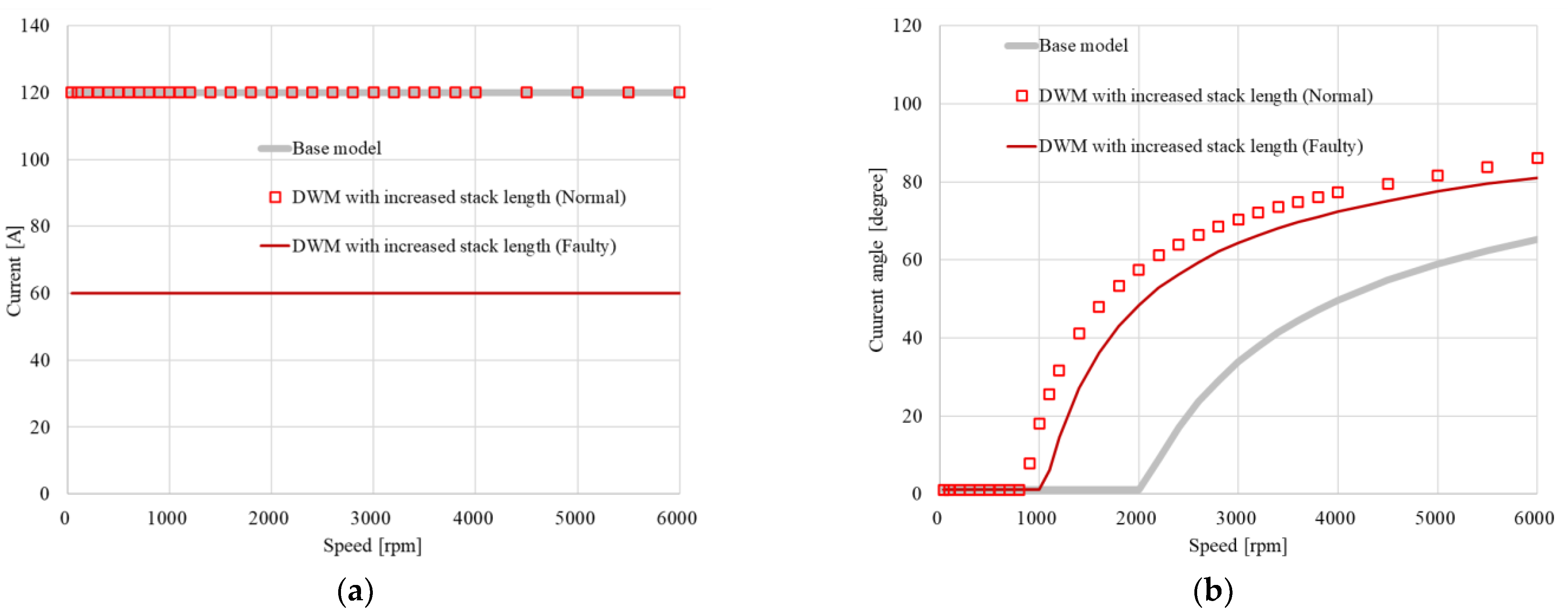
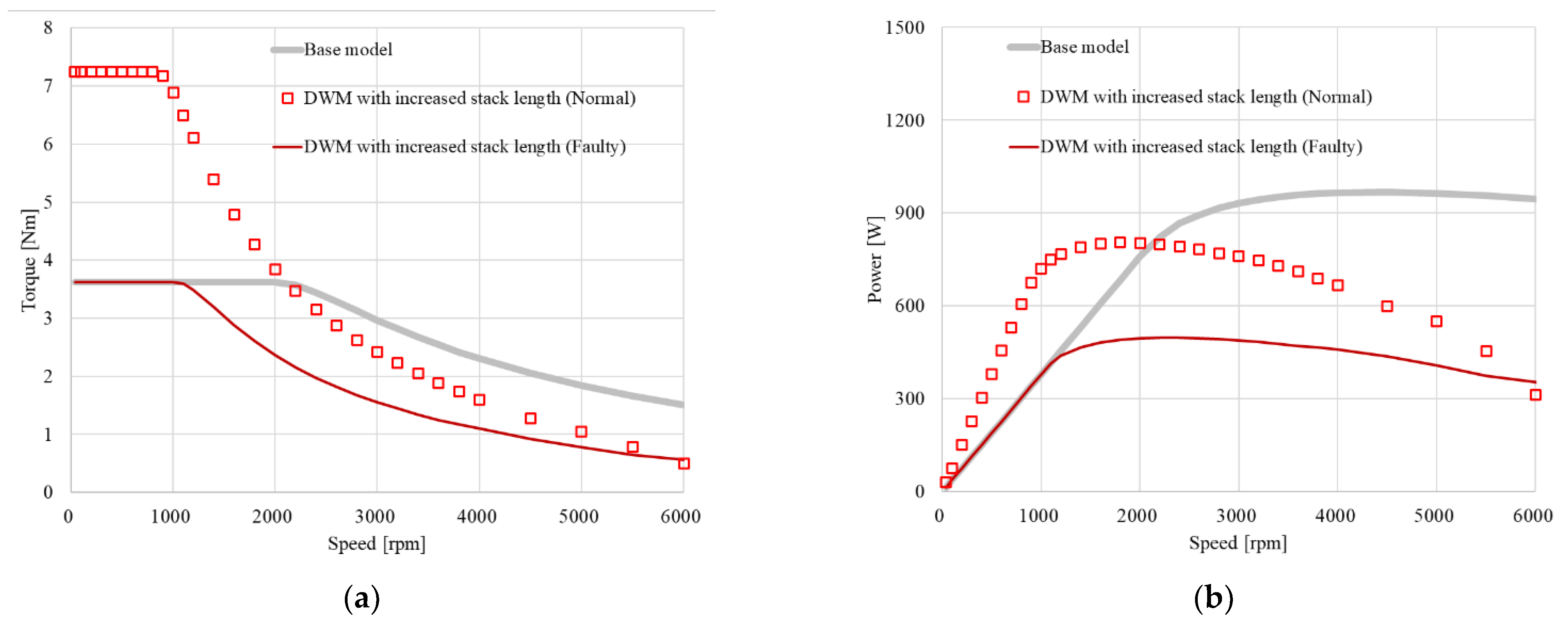
3.2. DWM with an Increased Stack Length

The design concept of the DWM stack length is illustrated in Figure 7. When the DWM operates in failure mode, the current consumption doubles because it operates with half of the motor. However, if the stacking length of the DWM is doubled, the increase in current during the fault operation can be compensated for. Since only the stacking length is changed while using the previously developed motor mold, the design is simple [13,26].
Table 3 presents a comparison of the control parameters for the DWM with an increased stack length and a previously developed base model. A comparison of the motor control parameters confirms that the resistance, flux linkage, and inductance increase in proportion to the increase in stacking length.
Since the conventional DWM has the same motor control parameter and loss values as the base model, the output performance is also the same. However, the DWM with an increased stack length has different motor control parameter values and loss values from the base model, thus the output performance is also significantly different.
The current vector control method [27] applied for the performance analysis of the base model and DWM with an increased stack length is as follows:
v d v q = R p h 0 0 R p h i d i q + v o d v o q  
v o d v o q = 0 ω · L q ω · L d 0 i d i q + 0 ω · Ψ a  
where Rph indicates the phase resistance of the motor, vd and vq represent the d-axis and q-axis voltages, respectively, id and iq represent the d-axis and q-axis currents, respectively, Ld and Lq represent the d-axis and q-axis inductances, respectively, ω symbolizes the electric angular velocity of the motor, and Ψa is the value of flux linkage by the permanent magnet and armature reaction.
The output torque and power of the motor are calculated as follows, based on the maximum available voltage and current of the motor, as shown in (2) and (3), respectively.
T = P · Ψ a i q + L d L q i d i q    
P O U T = T · w    
where T and P represent the torque and number of pole pairs, id and iq indicate the current values of the motors under the maximum output power control, and i d and i q vary before and after the base speed ω Q .
ω Q = V m Ψ a 2 L d I m 2
where Ψ a symbolizes the value of the flux linkages by the permanent magnet and the armature reaction.
Before reaching the base speed of the motor, it operates in MTPA control mode, and the id and iq values at this time are as follows:
i d = ψ a 2 L q L d ψ a 2 4 L q L d 2 + i q 2    
i q = I m 2 i d 2  
where I m indicates the amplitude of current.
When the speed of the motor exceeds the base speed, it operates in field weakening control mode. Here, id and iq are expressed as follows:
i d = ψ a L d ψ a L d 2 + L q 2 L d 2 ψ a a 2 + L d I m 2 V o m ω 2 L q 2 L d 2  
i q = I m 2 i d 2
The analysis results comparing the DWM with the increased stack length with the base model for the peak current and current phases under current vector control are shown in Figure 8. Figure 8a shows the current analysis results for normal and faulty operations of the base model and DWM with the increased stack length model. A DWM with an increased stack length doubles the stack length compared to the base model, thus only half the current is used. Figure 8b illustrates the current phases of the base model and DWM with an increase in the stack length model. Since the EMF of the base model is the smallest, the speed at which field weakening control starts is also the highest.
The results of comparing the DWM with an increased stack length with the base model for torque and output power under current vector control are depicted in Figure 9. Figure 9a shows the torque and output power analysis results for the normal and faulty operation of the base model and DWM with the increased stack length model. The DWM with an increased stack length generates the same amount of torque as the base model because of the increased stack length, even in a faulty mode in which only half of the motor is driven. Figure 9b shows the output power of the base model and the DWM with an increase in the stack length model. In the DWM with an increased stack length, the high-speed output performance is lower than that of the base model owing to the changed motor control parameters.
It is evident that the DWM with the increased stack length solves the overheating problem in the faulty mode but reduces the output performance in the normal mode.
In addition to the motor performance comparison, to compare the performance of the integrated electric brake system with the DWM with an increased stack length and the base model, the system response performance is analyzed, as shown in Figure 10. Current vector control [27,28,29] was used, along with the brake pressure load profile.
The concept of the power transmission path from the pressure load of the IEB to the motor torque load is illustrated in Figure 11. As shown in Figure 11, the motor shaft is integrally composed of a worm shaft. Motor torque is transmitted to the rack through a worm wheel and pinion. The rotational motion of the pinion is changed into linear motion through the pinion and rack structure. The pressure inside the pump can be reduced or increased through the linear motion of the rack. Equation (9) was used to convert the pressure load to the motor torque load in the response analysis [30].
The IEB load pressure profile P1LOAD (t) can be translated to the load torque profile TLOAD (t) as
T L O A D t = P 1 L O A D t · R D I A 2 2 · π · P 2 D I A 2 · W 1 G E A R R A T I O P 2 E F F 100 · W 1 E F F 100  
where TLOAD (t) and P1LOAD (t) represent the load torque and load pressure profiles with respect to time obtained from the results of the experiments conducted on the integrated brake system, respectively; RDIA and P2DIA represent the outer diameters of the rack and pinion gears, respectively; P2EFF and W1EFF indicate the efficiencies of the pinion and worm wheel gears, respectively; and W1GEAR_RATIO denotes the worm wheel pinion gear ratio.
As a result of the responsiveness analysis under normal conditions, as shown in Figure 12, the maximum speed decreases by approximately 20.52% from 6944 rpm to 5518 rpm under the same load operation conditions. In the event of a fault, some degree of deterioration in braking performance is allowed because a problem has already occurred in the vehicle or brake parts. However, as the IEB system in the normal mode is a new production part, it must guarantee the same level of braking performance as the base model.

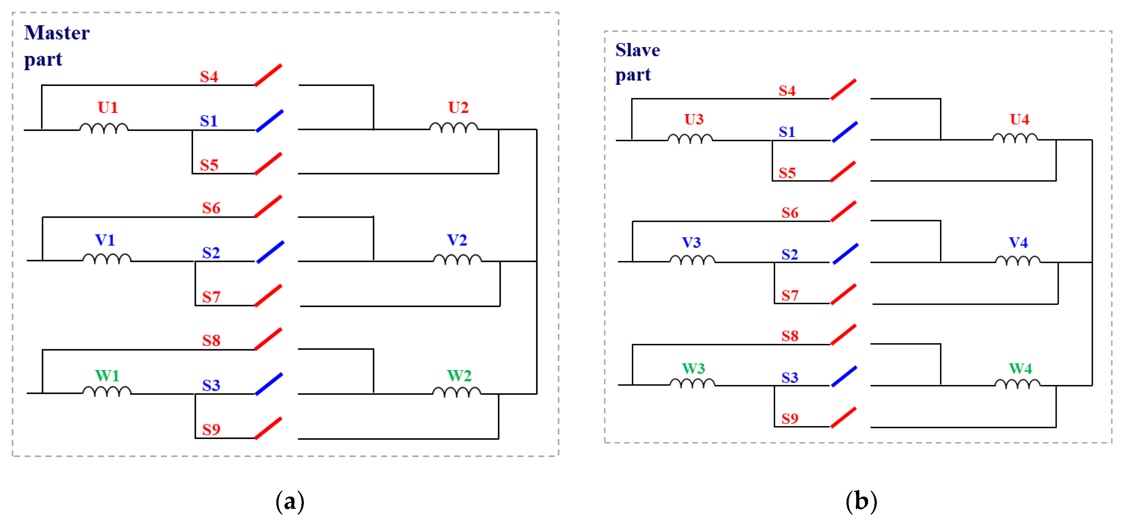
4. Proposed Dual Winding Motor with Winding Switching
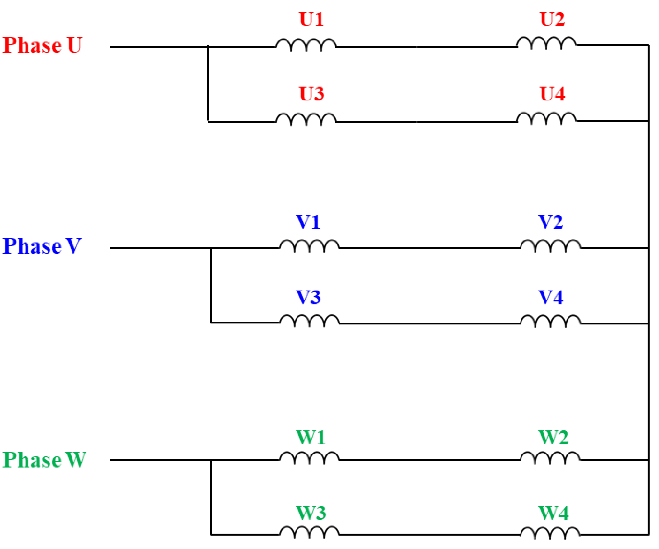
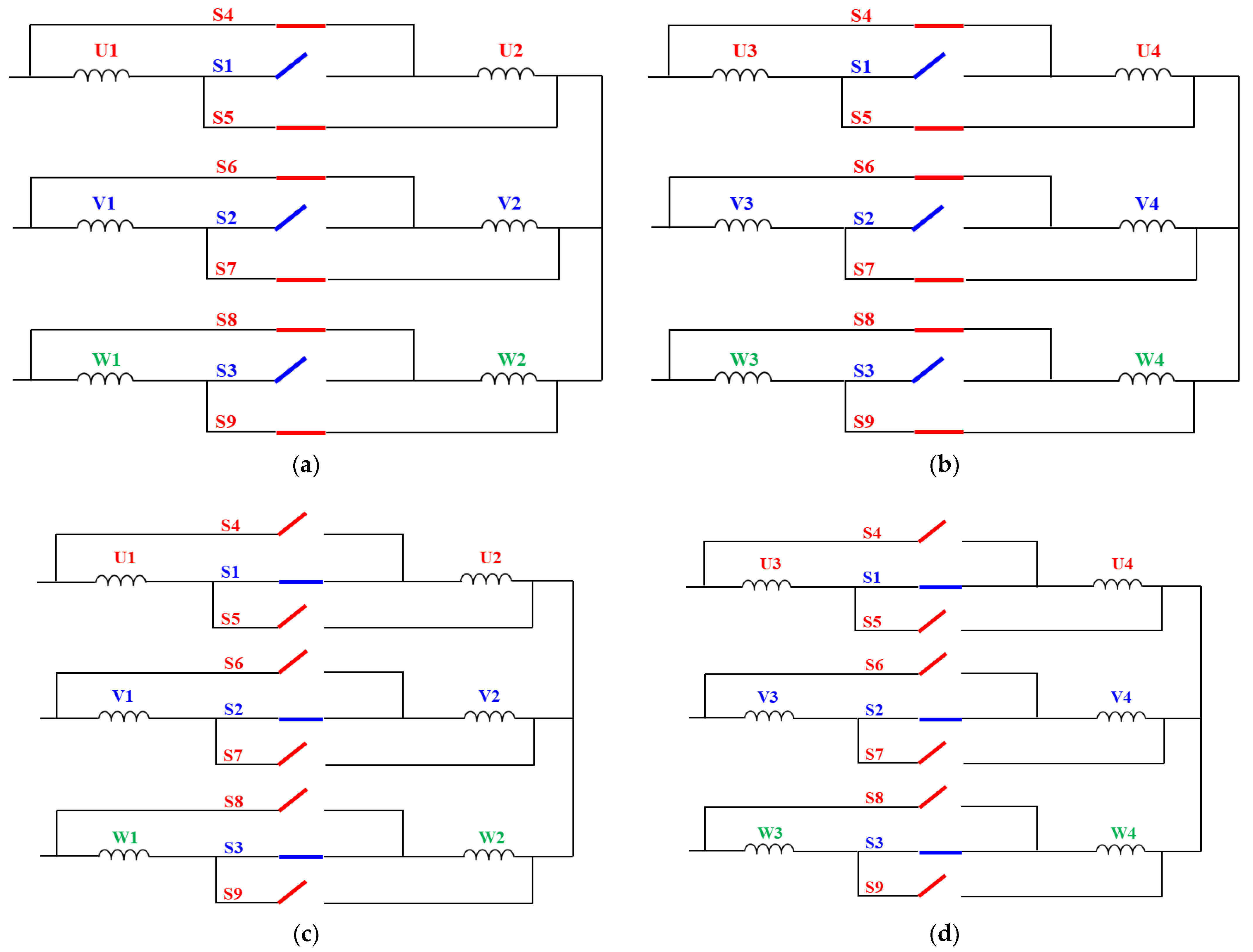
To improve the performance degradation problem in the normal mode of the DWM with increasing stack length described in the previous section, we propose a DWM using winding switching.

4.1. Topology

The topology of the proposed DWM with WS is as follows: The motor is identical to the base model and only winding switching was added. In the faulty mode, the overheating problem that can occur in the case of a fault is solved by controlling the winding switching to double the EMF constant. Additionally, there is no change in performance because it has the same specification as the existing base model in the normal mode. Figure 13 shows the proposed DWM with the WS. Figure 13a,b show the winding topologies of the master and slave parts, respectively. It consists of a total of nine switches and is connected to the input and output terminals of each slot winding, and the winding structure of the motor is changed by the switch ON/OFF status.
In the DWM, the switch connection state is different according to the normal mode and faulty mode, as listed in Table 4. In the normal mode, only switches S1, S2, and S3 are connected to implement a two-parallel winding structure.
Figure 14 shows the winding switching method for the proposed DWM. Figure 14a,b show the connection state of the switch between the master and slave parts in the normal mode. Figure 14c,d show the connection state of the switch between the master and slave parts in the faulty mode. It is evident that the total number of serial turns increases in the case of a fault.

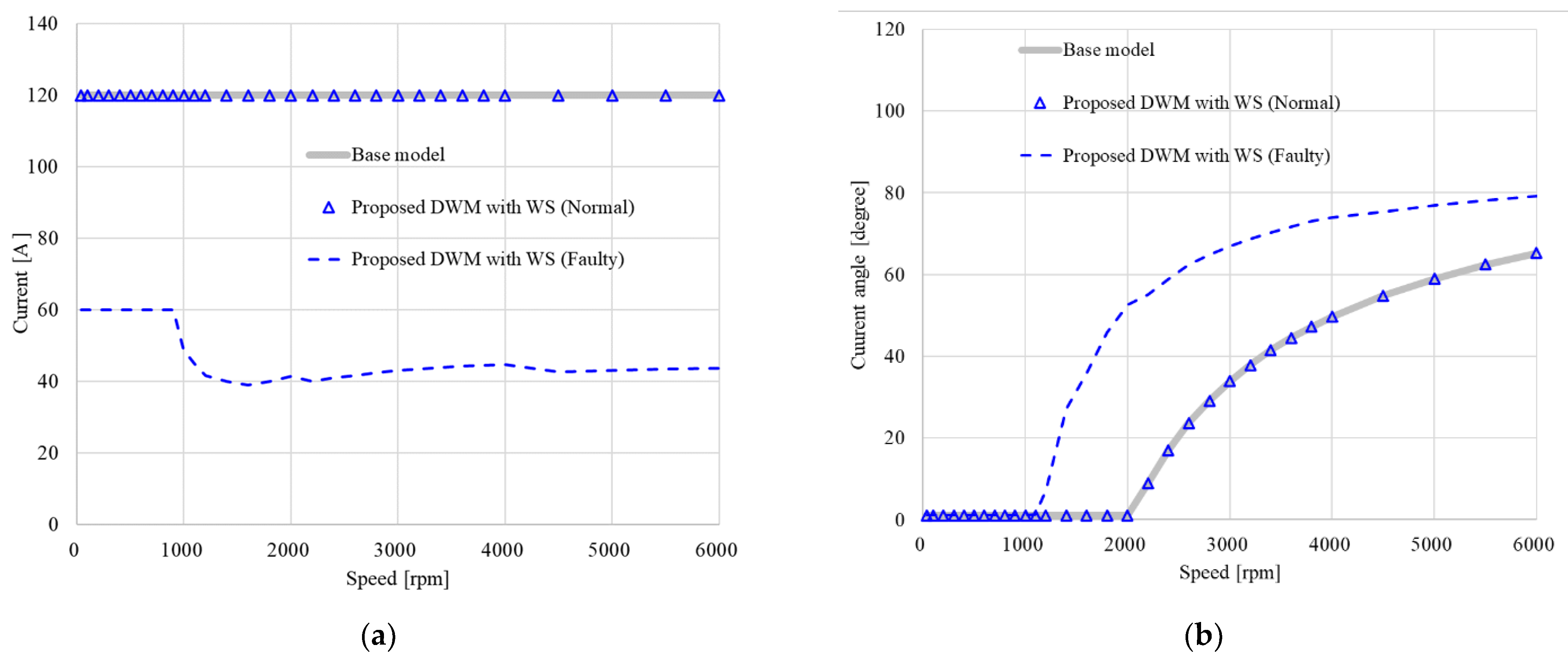
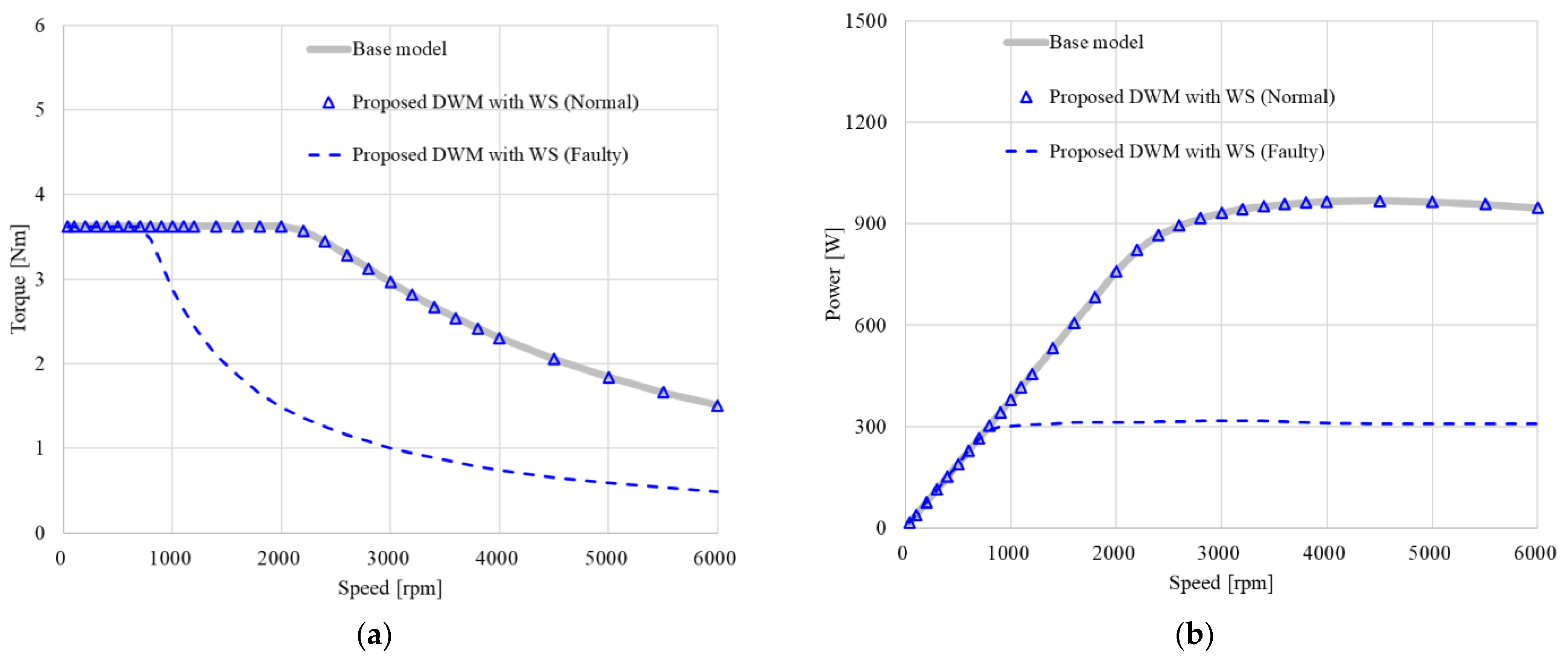
4.2. Performance Comparison

Table 5 lists the motor control parameters of the base model and the proposed DWM with WS under normal and faulty conditions.
Figure 15 shows the peak current and current angle analysis results under the current vector control of the base model and proposed DWM with WS, respectively. Figure 15a shows the results of the analysis. In the faulty mode, only half of the motor is used; however, only half of the current is required at the maximum torque because the number of series turns is doubled. Figure 15b shows the current angle during control, and it can be confirmed that it has the same value as the base model in the normal mode. Figure 16 shows the torque and output characteristics under the current vector control of the base model and proposed DWM with WS, respectively. Figure 16a,b show the torque and output power analysis results, respectively. In the faulty mode, the maximum output power decreases, but the maximum torque and current consumption are satisfied; therefore, there is no problem with vehicle braking. However, in quick braking mode, which requires high speed and high power, the braking performance of the vehicle is degraded. When operating in this failure mode, the vehicle is controlled only in the safe braking mode, without an emergency quick braking mode.
In the normal mode, the system has the same system response performance. In the faulty mode, it can be observed that the response performance of the system deteriorates due to the decrease in the current and the increase in the resistance. In the case of a fault, there is a decrease in responsiveness. However, it is not a problem because it is a special situation in which the fault state is recognized, and a sudden brake is not required. As shown in Figure 17, the performance degradation problem of the DWM with an increased stack length in the normal mode is solved.

5. Conclusions

In this paper, we proposed a DWM using WS to simultaneously solve the problem of overheating in the faulty mode of the DWM and degrade the performance of IEB systems in the normal mode. As a result of comparison, unlike the DWM with an increased stack length, which reduced the maximum speed by 20.5% compared to the existing base model during quick braking operation in the normal mode, the proposed DWM with WS enabled the design of a fault-tolerant DWM without performance degradation in the normal mode and overheating in the faulty mode by changing the number of series turns of the motor through switching modes I and II.
Furthermore, the proposed DWM with WS can compensate for the current increase in the faulty operation mode through the switching operation, thus it is unnecessary to increase the size of the motor. Moreover, it is advantageous in terms of size and weight compared to the well-known DWM with an increased stack length. In the future, the proposed DWM using WS will be actually implemented, and research on mass production and commercialization will be conducted. The proposed DWM can be applied not only to IEB systems, but also to various other redundant systems driven by motors.

Author Contributions

Conceptualization, K.-Y.H.; methodology, K.-Y.Y.; software, K.-Y.H.; validation, K.-Y.H. and K.-Y.Y.; writing—original draft preparation, K.-Y.H.; writing—review and editing, K.-Y.H. and K.-Y.Y.; funding acquisition, K.-Y.Y. All authors read and agreed to the published version of the manuscript.

Funding

This study was supported by a 2021 research fund from the Honam University. This research was also supported by the “Regional Innovation Strategy (RIS)” of the National Research Foundation of Korea (NRF) funded by the Ministry of Education (MOE) (2021RIS-002).

Acknowledgments

We would like to thank Editage (www.editage.co.kr, accessed on 15 January 2023) for the optimization.

Conflicts of Interest

The authors declare no conflict of interest.

References

  1. Zhang, Y.; You, T.; Chen, J.; Du, C.; Ai, Z.; Qu, X. Safe and Energy-Saving Vehicle-Following Driving Decision-Making Framework of Autonomous Vehicles. IEEE Trans. Ind. Elec. 2022, 69, 13859–13871. [Google Scholar] [CrossRef]
  2. Karnouskos, S. Self-Driving Car Acceptance and the Role of Ethics. IEEE Trans. Eng. Manag. 2020, 67, 252–265. [Google Scholar] [CrossRef]
  3. Rasouli, A.; Tsotsos, J.K. Autonomous Vehicles That Interact with Pedestrians: A Survey of Theory and Practice. IEEE Trans. Intell. Transp. Syst. 2020, 21, 900–918. [Google Scholar] [CrossRef] [Green Version]
  4. Guo, J.; Kurup, U.; Shah, M. Is It Safe to Drive? An Overview of Factors, Metrics, and Datasets for Driveability Assessment in Autonomous Driving. IEEE Trans. Intell. Transp. Syst. 2020, 21, 3135–3151. [Google Scholar] [CrossRef]
  5. Chen, S.; Chen, Y.; Zhang, S.; Zheng, N. A Novel Integrated Simulation and Testing Platform for Self-Driving Cars with Hardware in the Loop. IEEE Trans. Intell. Veh. 2019, 4, 425–436. [Google Scholar] [CrossRef]
  6. Hussain, R.; Zeadally, S. Autonomous Cars: Research Results, Issues, and Future Challenges. IEEE Commun. Surv. Tutor. 2019, 21, 1275–1313. [Google Scholar] [CrossRef]
  7. Bianchi, N.; Pre, M.D.; Bolognani, S. Design of a Fault-Tolerant IPM Motor for Electric Power Steering. IEEE Trans. Veh. Technol. 2006, 55, 1102–1111. [Google Scholar] [CrossRef]
  8. Muduli, U.R.; Beig, A.R.; Jaafari, K.A.; Alsawalhi, J.Y.; Behera, R.K. Interrupt-Free Operation of Dual-Motor Four-Wheel Drive Electric Vehicle Under Inverter Failure. IEEE Trans. Transp. Electrif. 2021, 7, 329–338. [Google Scholar] [CrossRef]
  9. Grandesso, G.; Bravo-Palacios, G.; Wensing, P.M.; Fontana, M.; Del Prete, A. Exploring the Limits of a Redundant Actuation System through Co-Design. IEEE Access 2021, 9, 56802–56811. [Google Scholar] [CrossRef]
  10. Song, B.K.; Chin, J.W.; Kim, D.M.; Hwang, K.Y.; Lim, M.S. Temperature Estimation Using Lumped-Parameter Thermal Network With Piecewise Stator-Housing Modules for Fault-Tolerant Brake Systems in Highly Automated Driving Vehicles. IEEE Trans. Intell. Transp. Syst. 2021, 22, 5819–5832. [Google Scholar] [CrossRef]
  11. Jiang, X.; Huang, W.; Cao, R.; Hao, Z.; Jiang, W. Electric Drive System of Dual-Winding Fault-Tolerant Permanent-Magnet Motor for Aerospace Applications. IEEE Trans. Ind. Electron. 2015, 62, 7322–7330. [Google Scholar] [CrossRef]
  12. Noh, Y.; Kim, W.; Lee, J. The Optimal Current Ratio Control of Redundant Electric Drive Systems and Diagnostic Strategies for Disagreement. IEEE Access 2021, 9, 32115–32130. [Google Scholar] [CrossRef]
  13. Hwang, K.Y.; Kim, S.I.; Song, B.K. Single Winding Type Determination of Dual Winding Three-Phase Motor Considering Overheat Problem in Integrated Electric Braking System of Autonomous Vehicles. IEEE Trans. Transp. Electrif. 2023, 9, 656–666. [Google Scholar] [CrossRef]
  14. Sin, S.; Ali, R.; Muhammad, A.; Kwon, B.I. Operation Method of Non-Salient Permanent Magnet Synchronous Machine for Extended Speed Range. IEEE Access 2020, 8, 105922–105935. [Google Scholar] [CrossRef]
  15. Sin, S.; Ali, R.; Kwon, B.I. Improvement of the Constant-Power Speed Range of Surface-Permanent Magnet Machine Using Winding Switching. IEEE Access 2021, 9, 32298–32309. [Google Scholar] [CrossRef]
  16. Arsalan, A.; Noman, B.; Muhammad, A.; Kwon, B.I. Wide-speed range operation of pm vernier machines using wye and wye-delta winding configurations. IEEE Access 2020, 8, 194709–194718. [Google Scholar]
  17. Muhammad, A.; Asif, H.; Jawad, G.; Kwon, B.I. Brushless Operation of a Wound-Field Synchronous Machine Using a Novel Winding Scheme. IEEE Magn. 2019, 55, 8635517. [Google Scholar]
  18. Muhammad, A.; Asif, H.; Jawad, G.; Kwon, B.I. Wye-delta winding configuration for brushless operation of a wound field synchronous machine. Int. J. Appl. Electromagn. Mech. 2020, 64, 1165–1172. [Google Scholar]
  19. Ali, R.; Hwang, K.Y.; Lee, S.H.; Kwon, J.W.; Muhammad, A.; Kwon, B.I. Dual-Mode Brushless Wound Rotor Synchronous Machine for High Starting Torque. IEEE Access 2022, 10, 41657–41663. [Google Scholar]
  20. Lim, M.S.; Hong, J.P. Design of High Efficiency Wound Field Synchronous Machine with Winding Connection Change Method. IEEE Trans. Energy Convert. 2018, 33, 1978–1987. [Google Scholar] [CrossRef]
  21. Song, B.K.; Kim, D.K.; Kim, S.I.; Park, H.J.; Lee, G.H.; Lim, M.S. Comparative study on surface-mounted permanent magnet motors with segmented and connected core for brake system. IEEE Access 2020, 8, 167930–167938. [Google Scholar] [CrossRef]
  22. Lee, J.S.; Lee, H.; Nah, W. Minimizing the Number of X/Y Capacitors in an Autonomous Emergency Brake System Using the BPSO Algorithm. IEEE Trans. Power Electron. 2022, 37, 1630–1640. [Google Scholar] [CrossRef]
  23. Jo, T.H.; Joo, K.J.; Lee, J. Control Strategy of Dual-Winding Motor for Vehicle Electro-Hydraulic Braking Systems. Energies 2019, 13, 5090. [Google Scholar] [CrossRef]
  24. Hwang, K.Y.; Yun, K.Y. Fault-Tolerant Design Process of Spoke-Type IPM Motor Considering Irreversible Demagnetization of PM in Integrated Electric Brake System. IEEE Magn. 2022, 58, 8206809. [Google Scholar] [CrossRef]
  25. Hwang, K.Y.; Song, B.K.; Kwon, B.I. Asymmetric dual winding three-phase PMSM for fault tolerance of overheat in electric braking system of autonomous vehicle. IET Electr. Power Appl. 2019, 13, 1891–1898. [Google Scholar] [CrossRef]
  26. Hwang, K.Y.; Kwon, B.I. Design of Low-Cost BLAC Motors for Integrated Electric Brake Systems. IEEE Access 2019, 7, 184183–184193. [Google Scholar] [CrossRef]
  27. Hwang, K.Y.; Kwon, B.I. System-level optimal design process of inverter-fed blac motor used for 12-48 v integrated electric brake system. IET Electr. Power Appl. 2019, 13, 1891–1898. [Google Scholar] [CrossRef]
  28. Hendershot, J.R.; Miller, T.J.E. Design of Brushless Permanent Magnet Machines, 2nd ed.; Motor Design Books: Venice, FL, USA, 2010. [Google Scholar]
  29. Leonhard, W. Control of Electrical Drives, 2nd ed.; Springer: Berlin/Heidelberg, Germany, 1996. [Google Scholar]
  30. Hwang, K.Y.; Yun, K.Y. Optimal Design of an Inverter-Fed PMSM for a Brake System Considering Variation in Motor Control Parameters and Input Voltage. Appl. Sci. 2022, 12, 1707. [Google Scholar] [CrossRef]
Figure 1. Integrated electric brake system.
Applsci 13 03442 g001
Figure 2. Operating sequence of the integrated electric brake system.
Applsci 13 03442 g002
Figure 3. Configuration of developed a base model.
Applsci 13 03442 g003
Figure 4. Winding topology of the base model.
Applsci 13 03442 g004
Figure 5. Configuration of conventional DWM.
Applsci 13 03442 g005
Figure 6. Winding topologies of conventional DWM: (a) Master part; (b) Slave part.
Applsci 13 03442 g006
Figure 7. Design concept of DWM with an increased stack length.
Applsci 13 03442 g007
Figure 8. Comparison of peak current and current angle characteristics between the base model and the DWM with an increased stack length: (a) Current; (b) Current angle.
Applsci 13 03442 g008
Figure 9. Comparison of torque and power characteristics between the base model and the DWM with an increased stack length: (a) Torque; (b) Power.
Applsci 13 03442 g009
Figure 10. Current vector control strategy for DWM using Simulink.
Applsci 13 03442 g010
Figure 11. Concept of the motor and pump gear system of the integrated brake system.
Applsci 13 03442 g011
Figure 12. Comparisons of the speed response characteristics between the base model and the DWM with an increased stack length.
Applsci 13 03442 g012
Figure 13. Winding topology of proposed DWM with WS: (a) Master part; (b) Slave part.
Applsci 13 03442 g013
Figure 14. Proposed winding switching method: (a) Mode I of master part; (b) Mode I of slave part; (c) Mode II of master part; (d) Mode II of slave part.
Applsci 13 03442 g014
Figure 15. Comparison of the peak current and current angle characteristics between the base model and the proposed DWM with WS: (a) Current; (b) Current angle.
Applsci 13 03442 g015
Figure 16. Comparison of torque and power characteristics between the base model and the proposed DWM with WS: (a) Torque; (b) Power.
Applsci 13 03442 g016
Figure 17. Comparisons of speed response characteristics between the base model and the proposed DWM with WS.
Applsci 13 03442 g017
Table 1. Specification of the base model developed for integrated electric brake systems.
ItemsUnitBase Model
Number of slots/poles-12/8
Outer diameter of statormm72
Stack length of stator mm34
Mechanical airgap mm0.5
Steel sheet of stator/rotor-50PN470
Line to line resistancemΩ21.5
Max. voltageV12
Max. currentA120
Min. torque constantNm/A0.03
Max. powerW900
Table 2. Comparison of motor control parameters between base model and conventional DWM.
ItemsUnitBase ModelConventional DWM
Master PartSlave Part
Max. peak voltageV14
Max. peak currentA120120 (=60 + 60)
Resistance L–LmΩ21.543
Flux linkageWb0.0053
D-axis inductanceμH35.370.5
Q-axis inductanceμH35.971.9
Table 3. Comparison of motor control parameters between base model and DWM with an increased stack length.
ItemsUnitBase ModelDWM with an Increased Stack Length
Master PartSlave Part
Max. peak voltageV14
Max. peak currentA120120 (=60 + 60)
Resistance L–LmΩ21.573.9
Flux linkageWb0.0053
D-axis inductanceμH35.3141.0
Q-axis inductanceμH35.9144.0
Table 4. Operation modes of the machine.
ModeONOFF
Mode I (Normal mode)S1, S2, S3S4, S5, S6, S7, S8, S9
Mode II (Faulty mode)S4, S5, S6, S7, S8, S9S1, S2, S3
Table 5. Comparison of motor control parameters between base model and DWM with WS.
ItemsUnitBase ModelProposed DWM with WS
@Normal@Faulty
Master PartSlave PartMaster PartSlave Part
Max. peak voltageV14
Max. peak currentA120120 (=60 + 60)60
Resistance L–LmΩ21.54386
Flux linkageWb0.00530.0106
D-axis
inductance
μH35.370.5282
Q-axis
inductance
μH35.971.9287
Disclaimer/Publisher’s Note: The statements, opinions and data contained in all publications are solely those of the individual author(s) and contributor(s) and not of MDPI and/or the editor(s). MDPI and/or the editor(s) disclaim responsibility for any injury to people or property resulting from any ideas, methods, instructions or products referred to in the content.

