Article

Dynamic Behavior of Aluminum Plates Subjected to Sequential Fragment Impact and Blast Loading: An Experimental Study

1
Mechanics of Materials and Constructions Department, Vrije Universiteit Brussel (VUB), Pleinlaan 2, 1050 Brussels, Belgium
2
Civil and Materials Engineering Department, Royal Military Academy, Avenue de la Renaissance 30, 1000 Brussels, Belgium
3
Defense Science and Technology, Civil Engineering Department, Military Research Center, Ministry of National Defense, Nabeul 8021, Tunisia
*
Author to whom correspondence should be addressed.
Appl. Sci. 2023, 13(6), 3542; https://doi.org/10.3390/app13063542
Submission received: 1 March 2023 / Revised: 7 March 2023 / Accepted: 8 March 2023 / Published: 10 March 2023
(This article belongs to the Special Issue Explosion Effects in the Built Environment)

Abstract

:
This paper presents a study on the dynamic behavior of thin aluminum plates subjected to consecutive fragment impact and blast loading. To this end, two separate experimental setups are used. In the first setup, 2 mm thick aluminum plates E N - A W - 1050 A - H 24 were subjected to the ballistic impact of fragment-simulating projectiles (FSPs). Experiments were carried out for FSP calibers of 7.62 mm and 12.7 mm considering both single impact and triple impacts with variations in the spacing of the impact locations. The out-of-plane displacement and in-plane strain fields were measured using digital image correlation (DIC) coupled to a pair of high-speed cameras in a stereoscopic setup. In the second setup, a subsequent blast loading was applied to the perforated plates using an explosive-driven shock tube (EDST). After the plates are perforated, the strain field around the holes depended on the caliber, the impact orientation of the FSP, and the distance between the impact locations. When the blast loading was applied, cracks tended to appear in areas of strain concentration between the perforated holes. It was found that the relative distance between the holes significantly influences the target’s response mode.

1. Introduction

In 2021, over 19,473 deaths and injuries were recorded around the world as a result of the use of explosives as a weapon [1]. Of these, 59% were civilians. More than 93% of the civilian casualties were recorded in populated areas. In today’s society, the threat of terrorism is ever-present and intentional explosions can occur in any high-density public environment. An increase in the number of terrorist attacks using improvised explosive devices based on home-made explosives has been recorded [2]. Shrapnel bombs, nail bombs, and pipe bombs are most often used. Explosions generate a blast wave that propagates in the air and accelerates the initially contained parts, such as ball bearings, nails, screws, bolts, and other randomly shaped fragments. Consequently, depending on the distance to the center of detonation [3,4], structures and materials located in the vicinity can be subjected to three different types of loadings: (i) a blast loading, (ii) impact of fragments, and (iii) a combined loading caused by both the blast wave and the fragment impacts. The latter causes a synergistic effect on the structure; therefore, its assessment is challenging. This means that there are cases where the structural response is more severe than the sum of the contributions caused by the separate actions of the blast loading and the fragment impacts [4,5,6,7]. A considerable amount of well-documented studies on the dynamic response of impact- or blast-loaded structures exist (e.g., [8,9]). On the contrary, the literature regarding the combined effect of blast and fragment impact loading on protective structures is rather scarce.
Over the past few years, scenarios where the fragment impact occurs before the blast wave have received increased interest. It is found that in such cases, the target undergoes the highest damage [10]. This can be explained by the reduced structural integrity of the protective barrier after exposure to the fragment impacts. The latter creates defects and weak points, facilitating fracture initiation when blast loading is applied.
Researchers and practitioners have tried to establish reliable and controlled experiments to improve the fundamental understanding of the combined effect of blast loading and fragment impact on materials and structures. Osnes et al. [11] investigated the blast response of pre-damaged laminate glass plates caused by ballistic impact perforation. They experimentally proved that the protective capability of the laminated glass is clearly reduced if it is pre-damaged by a fragment. Cai et al. [12] experimentally investigated the dynamic behavior of a multi-layered panel under combined blast and fragment impact loading. The results showed that when fragments impact the front surface of the panel before the blast wave, they initiate failure mechanisms on the rest of the panels aggravating the final damage caused to the structure. The same conclusions were supported by a more recent work by Li et al. [13]. They highlighted the influence of the time interval between the fragment impact and the blast loading on the response mode (cracking, dishing, and plugging) of an aluminum plate subjected to a combined loading.
Modern protective structure components tend to be more flexible and lightweight than traditional fortified structures (i.e., concrete structures). They can undergo large plastic deformations without experiencing a material fracture. The structural response of such components under the combined effect of blast wave loading and fragment impacts is therefore of interest [13,14]. Several research efforts addressing this issue have been reported on thin-walled metallic plates [15,16]. To address the problem of combined loading, the combined loading scenario is sometimes decomposed into two sequential loading events: fragment impact and subsequent blast loading. Given the complexity of the failure mechanisms related to the fragment impact itself and the diversity of its influence factors, it is often simulated by using plates with pre-cut defects. These demonstrate a reduced structural integrity due to fragment impact. This method allows the creation of specific geometries to be studied under exposure of the blast loading. Rakvag et al. [17] studied low-strength thin steel plates with squares and circular pre-cut defects subjected to a rapid change in pressure between the two plate sides. The pre-cut defects were symmetrically distributed around the center of each plate. It is emphasized that the spacing between the different pre-cut defects was kept constant in all experiments. The authors concluded that the pre-cut defects’ shape, size, and number strongly affect the fracture resistance during blast loading. Moreover, they found that the smallest deflection is recorded for the plates with circular holes independent of the pressure loading. Inspired by these results, Li et al. [15] investigated the influence of different pre-cut geometries on the blast response of high-strength steel plates. The blast loading was generated by detonating varying amounts of TNT placed at a fixed distance from the plates. They observed that only plates with diamond-shaped defects fractured during testing. The plates with circular and square defects were indifferent to the various blast intensities. They concluded that a defect’s shape alters the plates’ resistance to fracture. Granum et al. [16] investigated the blast response of thin aluminum plates with different pre-formed defects. They discovered that besides the defects’ shape and number, both the orientation and spatial distribution significantly affect the fracture pattern and the plate’s crack path.
In the aforementioned studies, it should be highlighted that the pre-cut defects represent idealized geometries with no plastic deformation, as one would expect from a real fragment impact. Even though they may imitate the geometrical defects induced by a fragment impact, pre-cut defects do not represent the actual physics of the problem. When an actual fragment perforates a plate, material damage occurs in the proximity of the impact zone. An area of plastic strain is created around the hole with sharp notches and petalling cracks. This amplifies the crack growth on the crack tip when the plate is exposed to a subsequent blast loading. Ignoring this phenomenon can lead to a non-conservative estimation of the actual fracture resistance under blast loading. To aid the design of protective structures, a limited number of studies were performed on blast-loaded plates perforated with real fragments. Elveli et al. [18] studied the effects of pre-cut circular holes compared with pre-formed ballistic impact on the dynamic behavior of thin steel plates exposed to blast loading. The plates were perforated using small-arm projectiles fired from a fixed rifle. Subsequently, they were loaded using a shock tube facility [19]. The pre-cut holes had the same circular shape and diameter as the ballistic impact holes. The latter introduced plastic deformation and petalling cracks to the material around the impact zone. During blast loading, a propagation of the petalling cracks was observed. A reduced fracture resistance was found in the case of plates with ballistic impact perforation. More recently, Yu et al. [20] compared two experimental techniques for generating combined loading. In the first, steel plates with pre-formed holes at the plate center were exposed to pressure pulses. In the second, intact plates were exposed to sequential single-fragment impact and blast loading using a composite projectile fired from a gas gun facility. The composite projectile consisted of a closed-cell metallic foam and an embedded fragment-simulating projectile (FSP) where the FSP mimics the fragment impact on the plate and the foam simulates the applied blast loading. The central deflection, the failure modes, and the deformation processes of target plates obtained from the analysis of the two experimental techniques were compared. It was found that plates subjected to composite projectile impact at high impact velocity are more susceptible to tearing fracture. Therefore, specific cases exist where the idealization of an FSP impact as a pre-formed hole in the target will under-predict the actual damage caused by sequential FSP impact and blast loading. Although the proposed experimental technique highlights the influence of the fragment impact velocity on the plates’ tendency to fracture, the conclusions only hold for the case of a single fragment impact. Thus, it is still desirable to extend their applicability by investigating other influencing parameters such as the number of perforations and the hole spacing.
The aforementioned studies on structures and materials provide insights into (i) the different approaches and experimental techniques used to replicate combined blast and fragment impact loading, (ii) the encountered challenges in generating a reproducible loading, and (iii) the response of the different targets with respect to fragment impact, blast, or both loadings. This study has three main objectives: (i) contribution to the knowledge of how deformation and damage in plate-like materials subjected to a consecutive loading of fragment impact and blast wave are affected by projectile parameters such as size, shape, and number; (ii) investigation of the influence of the relative distance between impacts (hole spacing) on the fracture resistance during blast loading; and (iii) establishment of a comprehensive experimental data set that allows the development of computational methods for numerically investigating the dynamic behavior of plates exposed to the combined effect of blast and fragment impact loading.
The proposed test method in the present work is based on exposing thin aluminum plates to the impact of either a single or three FSPs. Subsequently, the perforated plates are subjected to a controlled planar blast wave via an explosive-driven shock tube. Stereoscopic high-speed digital image correlation (DIC) is used for result analysis. This technique enables focus on: (i) the local deformation on the impact zone activated by the fragment impact and (ii) the global deformation due to the blast loading.

2. Dynamic Behavior of Thin Aluminum Plates Subjected to the Impact of Fragment-Simulating Projectiles

2.1. Experimental Setup

The first part of the experiments was conducted using the launcher of the Accredited Ballistic Applications Laboratory (ABAL) at the department of ballistics at the Royal Military Academy [21]. It allows impact of a target with a fragment-simulating projectile with a user-defined range of velocities. A universal receiver houses a barrel corresponding to each projectile to be pyrotechnically propelled’s caliber. The layout of the experimental setup is shown in Figure 1.
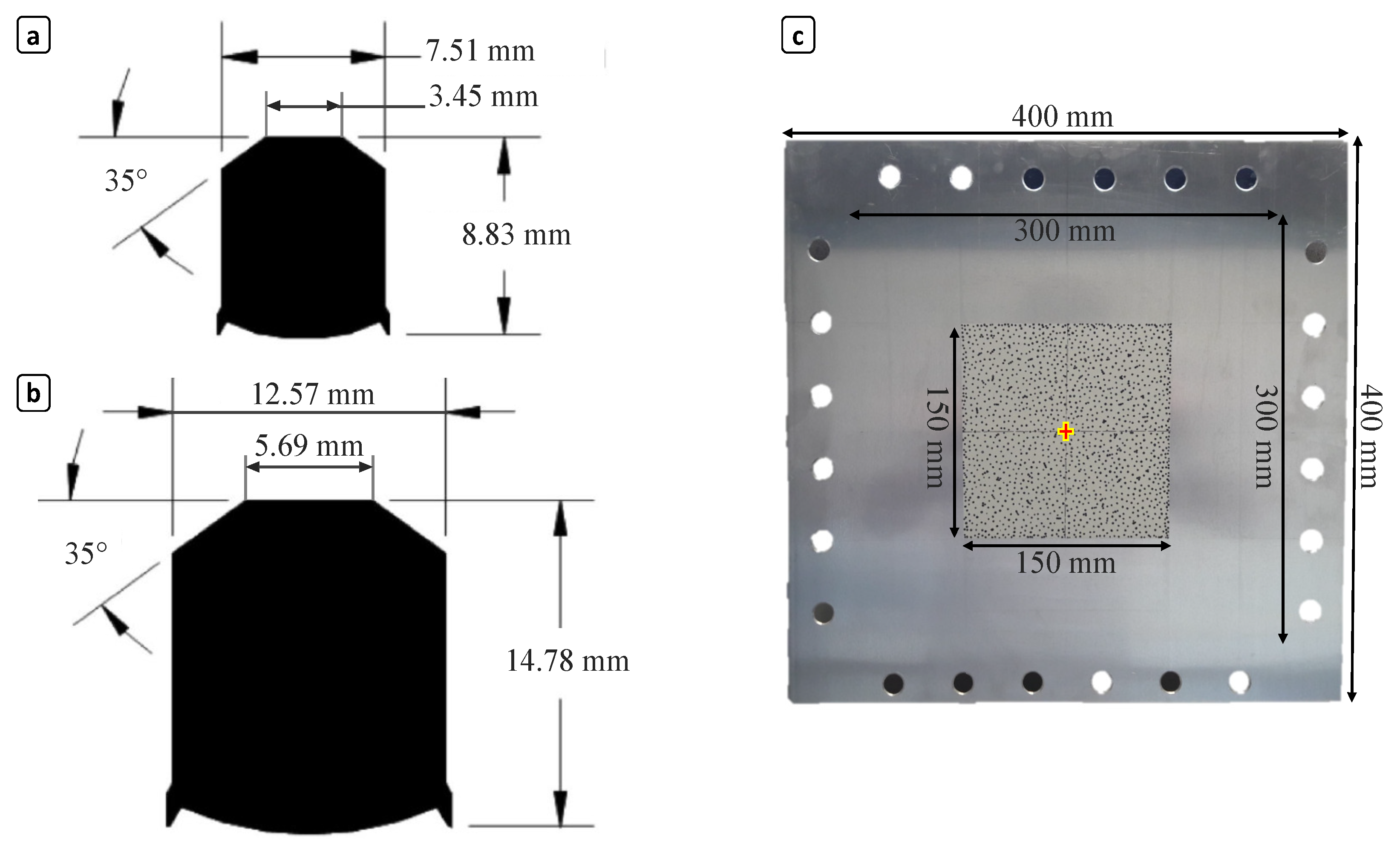
Two FSP calibers were used for the different tests: 7.62 mm and 12.7 mm. They were accelerated up to ± 325 m/s by means of a powder gun. The FSP dimensions were taken from STANAG-NATO [22] and are described in Figure 2a,b. The FSP in-flight velocity was measured by a double infrared velocity screen placed 2 m from the muzzle of the launcher. The distance was chosen to avoid interference with the muzzle flow that may trigger the counter of the velocity gates [23]. The system consisted of two sets of infrared gates. Each set was connected to a counter which recorded the time elapsed between the projectile passage through both gates. The FSP’s initial velocity was chosen to be higher than the target’s ballistic limit velocity. This choice limited the deformation to a small region around the impact point. The aluminum plates (commercial code E N - A W - 1050 A - H 24 ) [24] were fixed to a steel frame. They were positioned at a distance of 5 m from the launcher. The selected plate thickness is intended to create localized plastic deformation around the impact point while facilitating energy dissipation through deformation under blast loading. Table 1 provides the material properties and plate dimensions.
The aluminum sheet was a commercial aluminum alloy that belongs to the 1000 series aluminum alloys. The aluminum alloy was strain hardened and partially annealed, giving it moderate strength and improved formability. The material was annealed at a low temperature to relieve stress and prevent further strain hardening. The central part of the aluminum specimens was painted by application of a white background and a black speckle pattern as shown in Figure 2c. A study was conducted to determine the optimal speckle pattern parameters for the setup.
During the experiments, the plate behavior was observed using a field of view of 300 mm × 300 mm. Two Photron Fastcam S A 5 high-speed cameras HSC (cameras 2 and 3) were mounted in a stereoscopic configuration to record synchronized images during the impact process. The high-speed cameras were placed behind a shield protector at a safe distance from the plate in order to avoid damage from the projectiles. Two light-emitting diodes LEDs were used to increase the illumination of the aluminum plate. This was performed to maintain adequate contrast throughout the experiment.

2.2. Experimental Program

Four different configurations were tested. A total of ten ballistic impact tests were performed. The experimental program aims to investigate the influence of the size of the FSP, the number of perforations, the impact position, and the relative distance between the holes on the failure characteristics of the target. A summary of the performed experiments is given in Table 2.
Configuration 1 studies the impact of a 7.62 mm FSP at three different impact positions. Configuration 2 studies the impact of a 12.7 mm FSP on the center of the target. Configuration 3 represents the impact of three 7.62 mm FSPs at different impact positions with different distances (hole spacing) between the three impacts. Configuration 4 represents the impact of three 12.7 mm FSPs with reduced spacing between the impacts.

2.3. Experimental Results

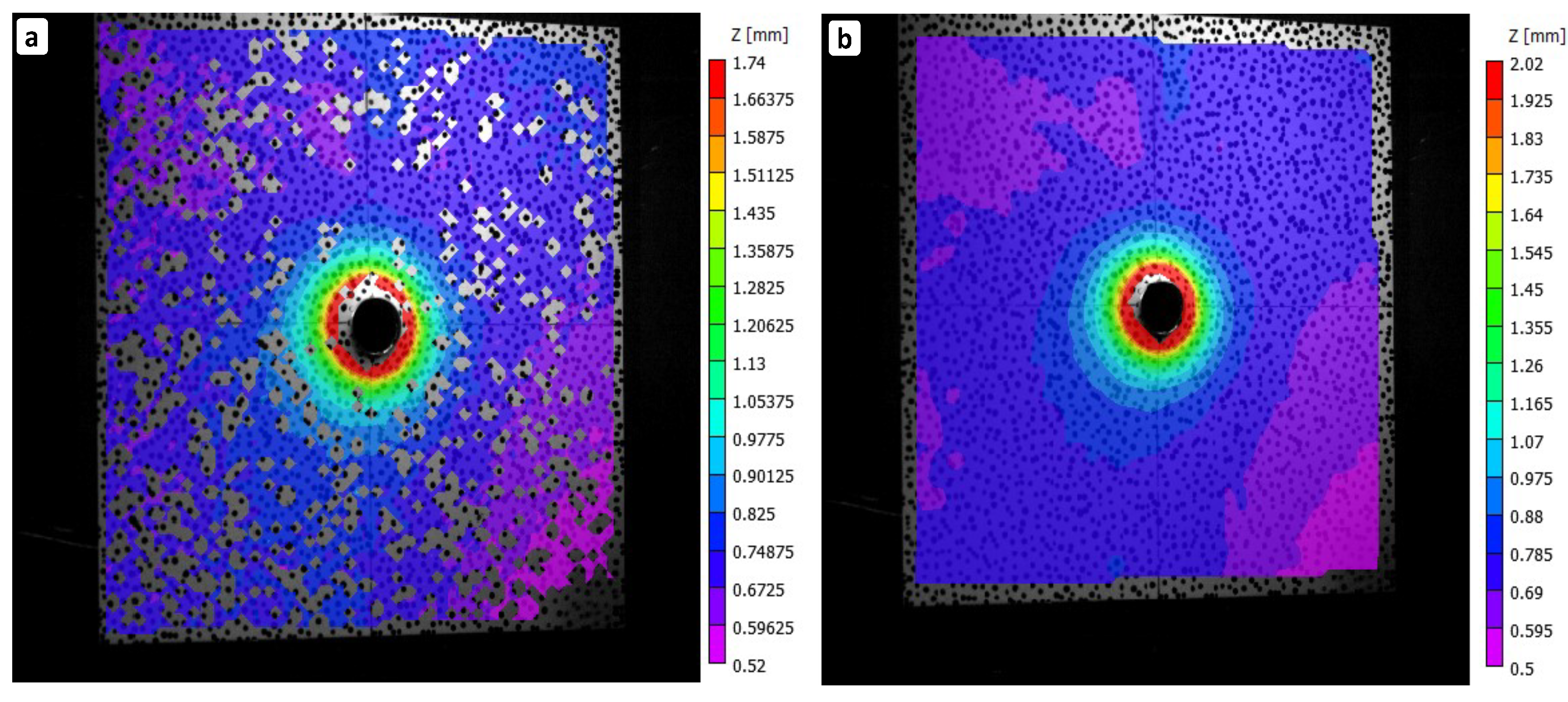
The results of the different performed experiments were analyzed using the DIC technique. In this paragraph, the focus is on the out-of-plane displacement and the in-plane strains due to the impact of the FSPs. The fundamental principles of the method are well described in [25]. A parametric study was conducted to choose the optimal parameters for the DIC analysis. The choice of the subset size influences the deformation results. On one hand, choosing a high subset value leads to a loss of spatial information around the impact zone. On the other hand, choosing a smaller subset size leads to noisy results or even to an impossibility of calculating the deformations. For example, Figure 3 compares the out-of-plane displacement field obtained using subsets of 9 and 21, respectively. The subset spacing was set to 5. The strain filter size defines the gauge length that is considered for the strains calculation. If the filter size is small, a higher resolution and noisier data are obtained and vice versa. A pixel subset of 21, a subset spacing of 5, and a strain filter size of 15 are finally considered for result analysis.

2.3.1. Plates Subjected to a Single FSP Impact

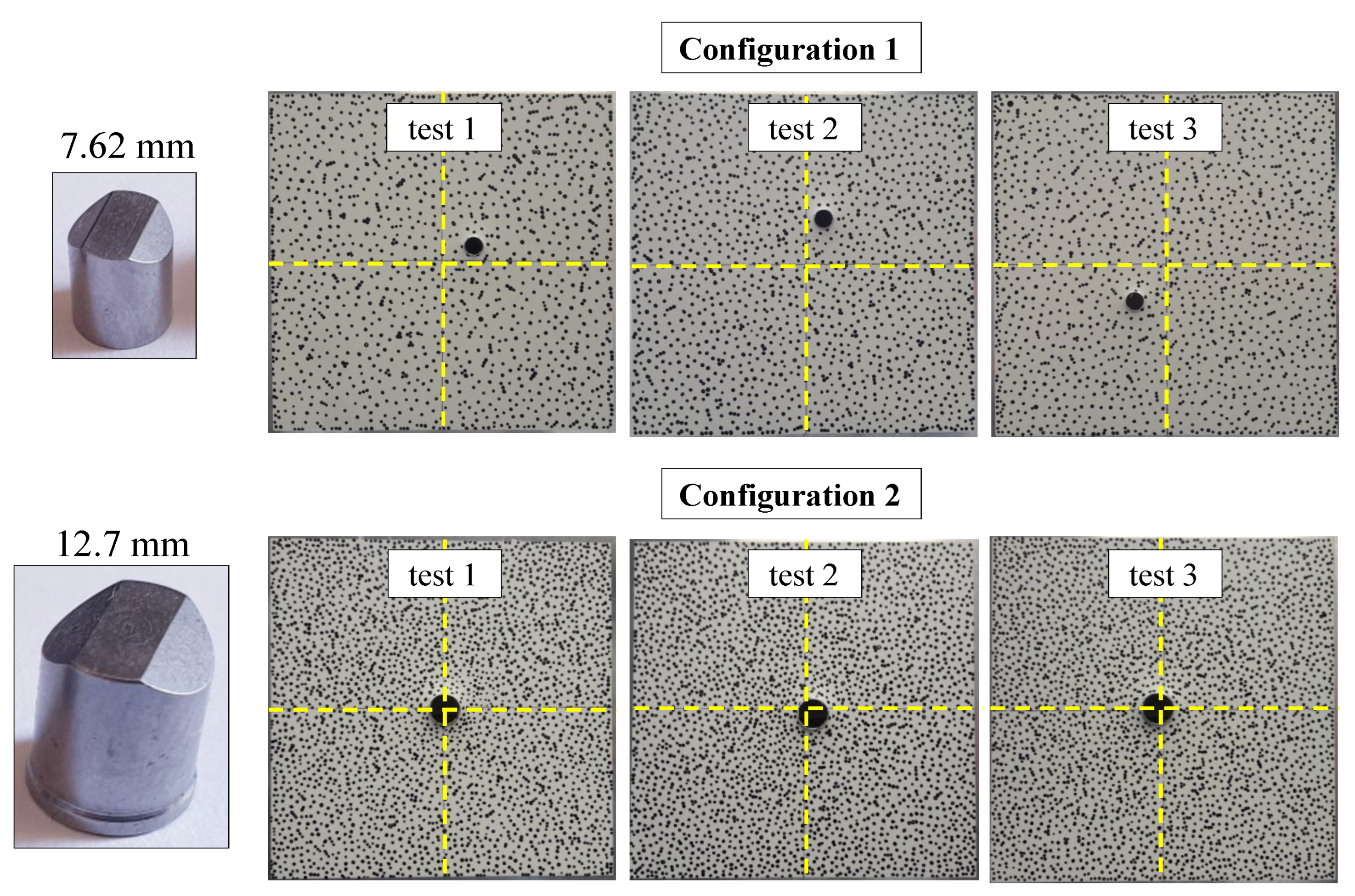
For each test, the full-field out-of-plane displacement and the in-plane strain fields are extracted. Figure 4 represents a plane view of the aluminum plate specimens in configurations 1 and 2 after full FSP perforation.
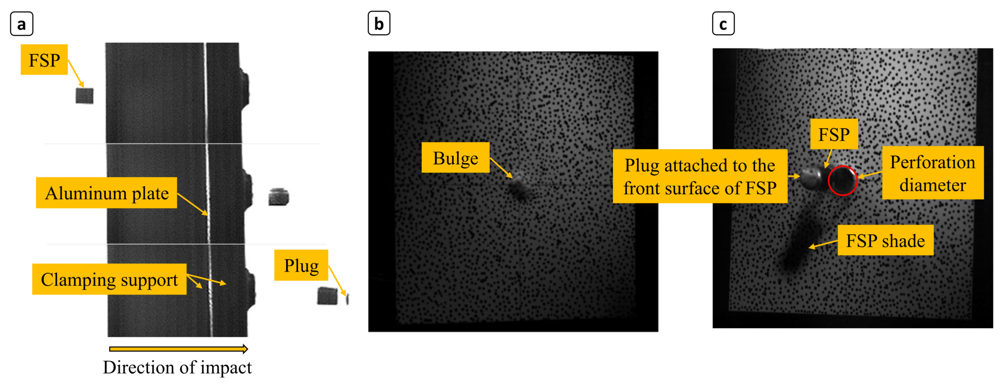
As a first observation, plugging failure is found as the predominating failure mode for all tests in both configurations. Because the plates are thin (2 mm), the FSPs with the lowest tested velocities accomplished perforation. Evaluation of the images obtained from HSC 1, as shown in Figure 5a, reveals that the FSP pitch angle both before and after the ballistic impact is low (Video S2). It is highlighted that no plastic deformation or visual damage occurs in all of the projectiles. Both configurations’ penetration and perforation processes are recorded using HSC 2 and 3. It is shown that at the moment of impact, the FSP causes a localized bulge at the rear side of the plate as illustrated in Figure 5b. A localized shearing of material induced by the FSP front surface is created in the contact zone. Immediately after, the FSP penetrates, and a circular plug is punched through the plate, leaving a clean-cut hole. Subsequently, the punched plug can be seen attached to the front surface of the projectile as shown in Figure 5c. After that, the punched plug is separated from the FSP. The red circle in Figure 5c highlights the perforation hole. No significant differences in the failure mode are noticed between the different tests of each configuration.
It should be highlighted that the FSP front surface cannot be captured by high-speed cameras 2 and 3 during impact due to the plug covering the FSP face. The FSP undergoes rotation from the moment it exits the launcher until it fully perforates the plate, which makes it challenging to determine the exact angle of impact. To address this, the high-speed images captured by cameras 2 and 3 are analyzed, and the front surface of the FSP is tracked at different time steps for each test of all configurations. Figure 6 provides an example for the second test of configuration 2. The red rectangle represents the FSP’s front surface, and the angle ϕ indicates the impact angle relative to the plate.
It is found that 12.7 mm size FSPs create larger local deformations. As an example, Figure 7 displays the 3D out-of-plane displacement field of the second test of configuration 2. The 3D out-of-plane displacement fields were extracted from the VIC 3D V8 software and exported as MATLAB figures. It is shown that the entire plate responds to the impact. However, the maximum displacement of 3.2 mm is exclusively observed in the immediate vicinity of the impact hole. It is highlighted that points placed at different orientations (0 , 45 , 90 , 135 , and 180 ) from the center of the impact point exhibit different out-of-plane-displacements.
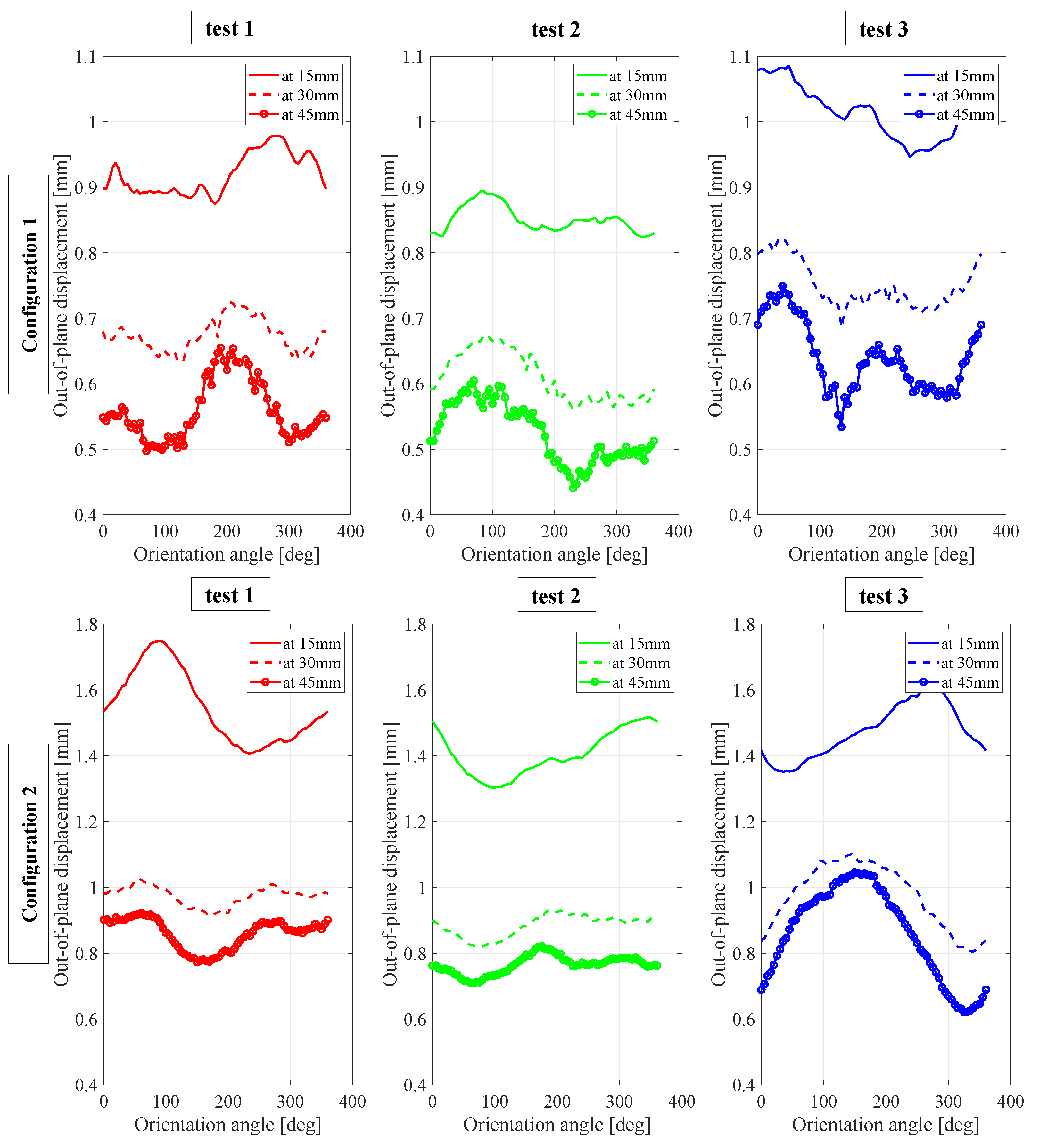
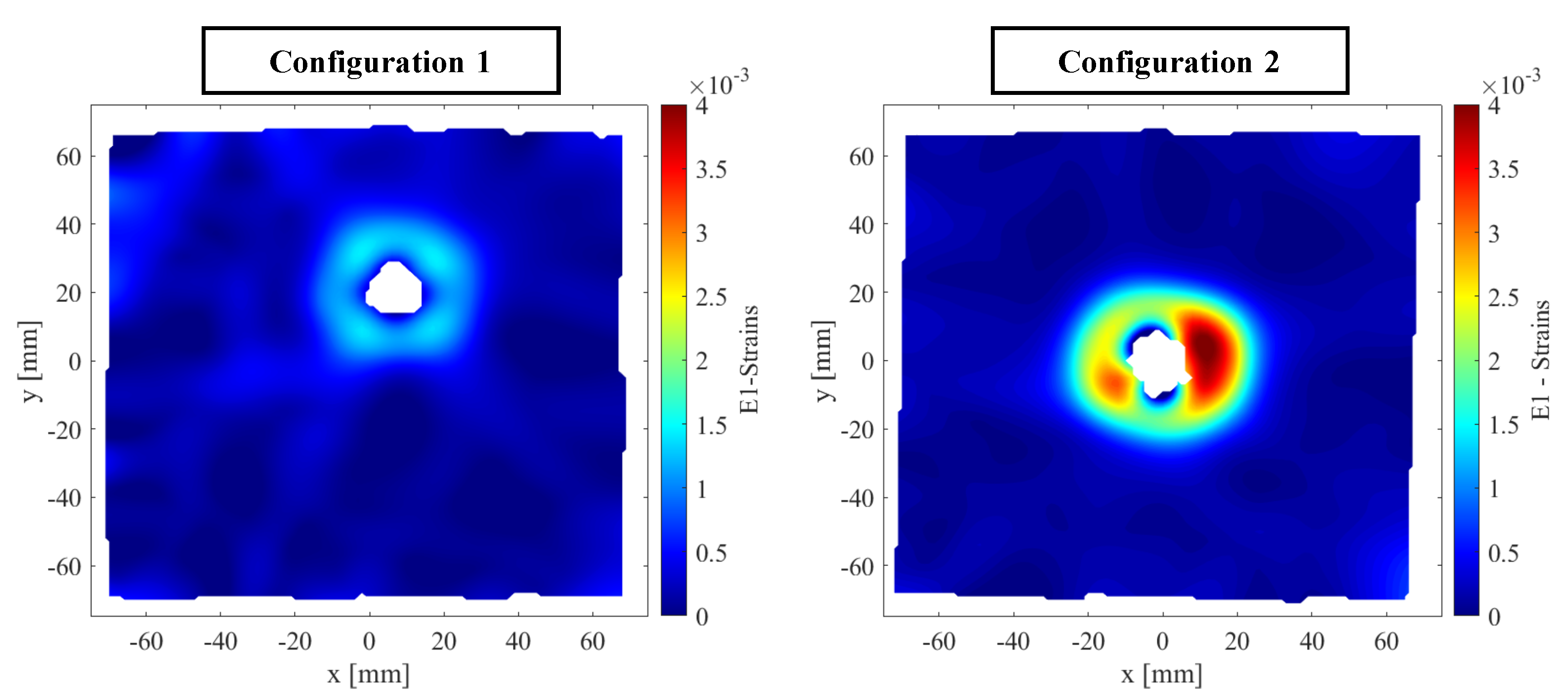
In Figure 8, the out-of-plane displacement of points located on three circles with a given radius (15 mm, 30 mm, and 45 mm) and centered on the impact coordinates are analyzed and shown for configurations 1 and 2. It should be noted that an angle of 0 corresponds to a point placed horizontally at the right side of the impact hole and increases counterclockwise. For both configurations, the maximum out-of-plane displacement is recorded for points placed on the closest circle to the impact center. An analysis of the HSC images of the ballistic event highlights that the FSP effect is directly related to its caliber. This finding is confirmed by analyzing the in-plane strain fields corresponding to configurations 1 and 2. For example, the major principal strains of the second test of both configurations are represented in Figure 9. It is found that 12.7 mm size FSPs induce larger strains.
In Figure 10, the major principal strains of points situated on the same three circles (as previously described) are analyzed and presented for the second test of configuration 2. The results suggest that the orientation of the FSP front surface at the moment of impact affects the magnitude of the major principal strain near the hole.
Two main conclusions are extracted from the analysis of the DIC results of both configurations. The first one reveals that plugging is the main failure mechanism in the plates. The second uncovers that the same strain orientation pattern appears in all specimens regardless of the FSP’s size or position on the target. However, the strain amplitude is influenced by the FSP caliber.

2.3.2. Plates Subjected to Three FSP Impacts

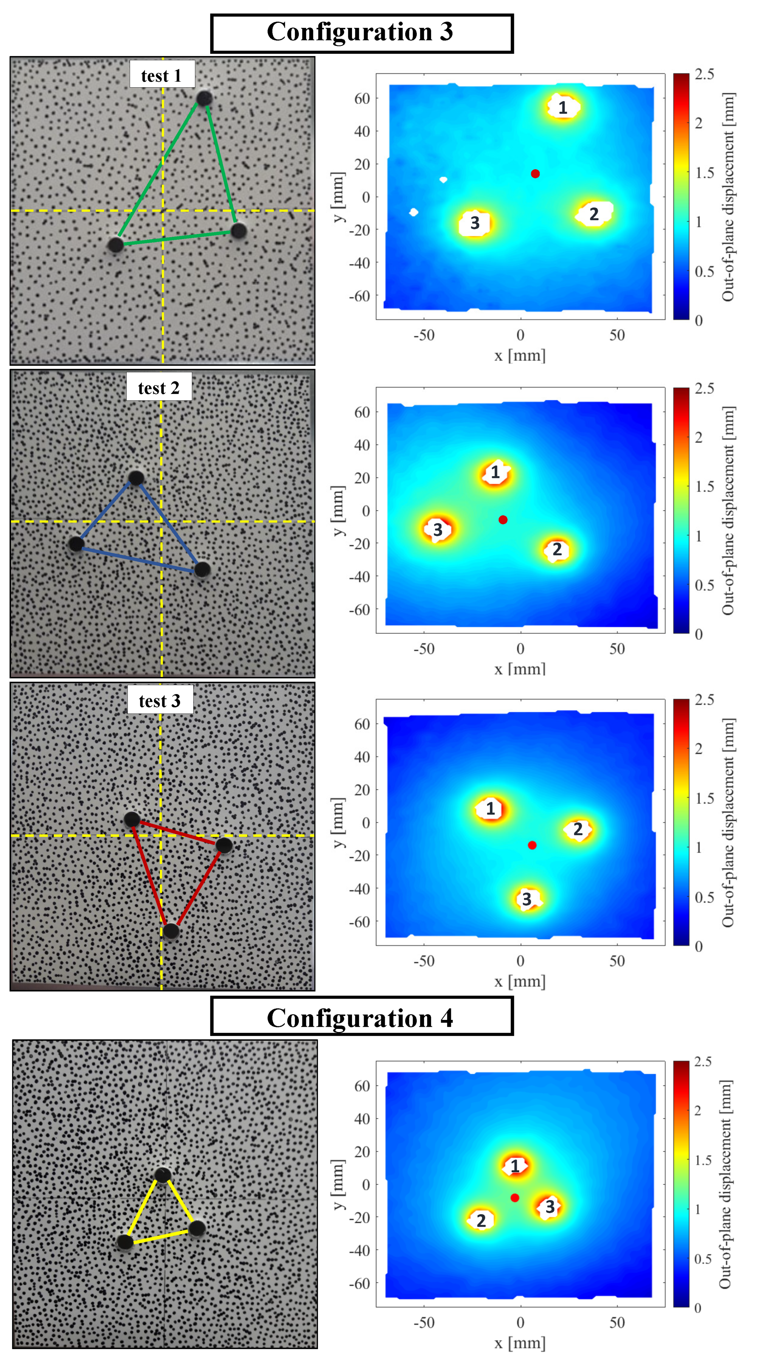
In the next series of tests, three separate consecutive shots were carried out on each plate. This means that each FSP impacted a plate at rest. Figure 11 represents a plane view of the aluminum plate specimens of configurations 3 and 4 after full perforation by three 7.62 mm and three 12.7 mm FSPs, respectively.
The figure also shows the corresponding out-of-plane displacement fields of the performed tests. Each red dot represents the geometrical center of the three impact holes. The numbers 1, 2, and 3 indicate the order of impact of the different FSPs. At first sight, neither small cracks nor petal-like deformations are observed around the impact zones of both configurations. The plates only experienced a small bending deformation in the direction of impact. However, the small displacements of the plate at some distance from the hole caused by each FSP impact seem to combine. Indeed, each impact leads to a given plastic out-of-plane displacement. This results in a zone of maximum displacement inside and in the vicinity of the triangle formed by the three impacts. Although the displacements may appear insignificant, they contribute to an overall deformation from the plate’s center to the periphery of the impact zone, encompassing the entire triangle formed by the three impacts.
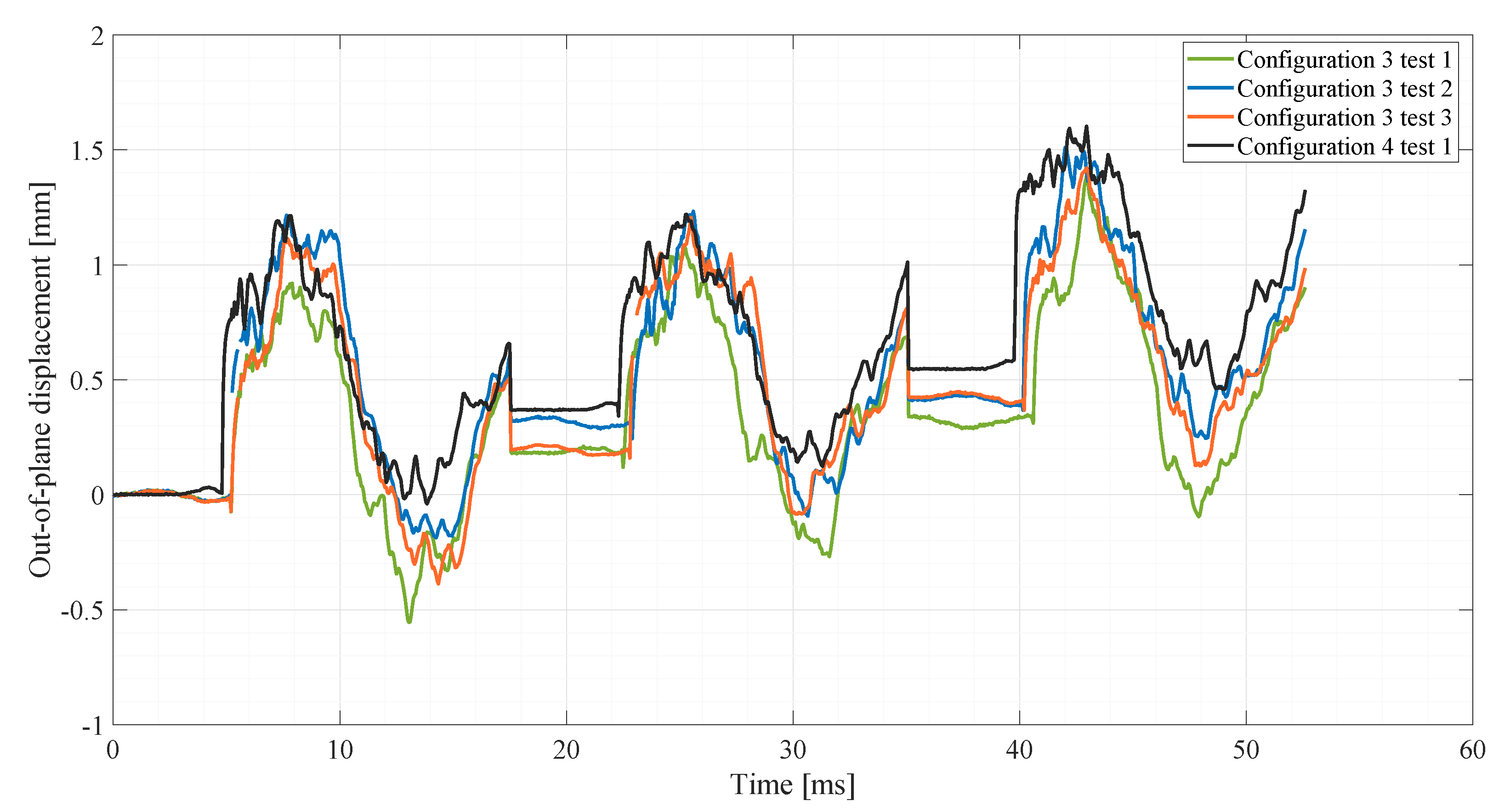
Figure 12 compares the different tests in terms of the out-of-plane displacement history of the geometrical centers of the holes shown in Figure 11.
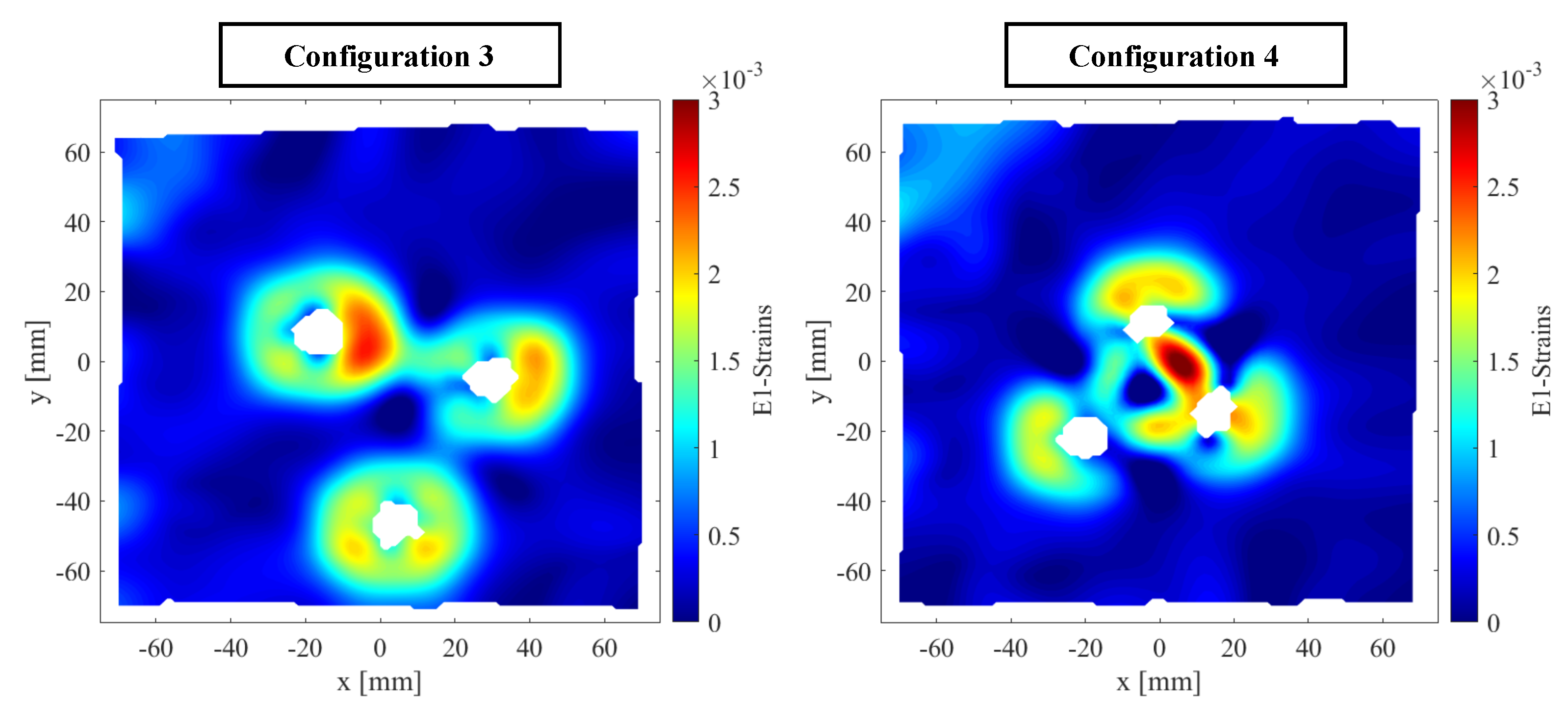
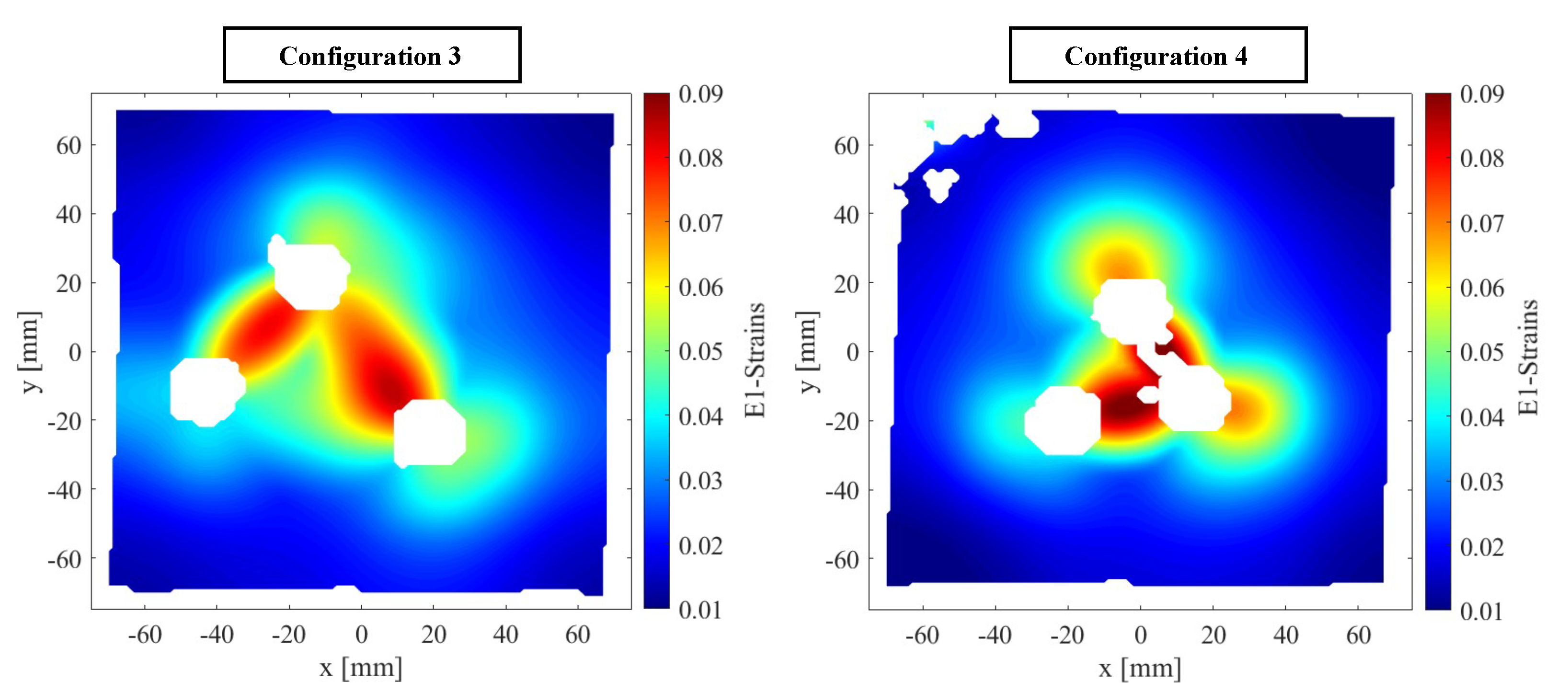
Three oscillating parts can be distinguished. Each part corresponds to the plate’s response after a single impact. The flat parts, or plateaus, represent the residual plastic deformations either before or after an impact. Configuration 4 shows the largest plastic deformation. This is because the impacts are closer to one another and the center of the plate and because of the use of 12.7 mm FSPs in that configuration. The analysis shows that the out-of-plane displacements due to the projectile impacts depend on the relative impact positions and the distance with respect to the center of the plate. In addition to the out-of-plane displacements, the strains are also computed. The major principal strains are represented in Figure 13 for the third test of configuration 3 and the test of configuration 4. The typical pattern observed for a single impact is still present. However, it can be seen that the typical “strain patterns” for each individual impact influence each other. These interactions between the strain patterns of each impact are more important for closer impacts (case of configuration 4).

3. Dynamic Behavior of Blast-Loaded Aluminum Plates Pre-Perforated by Ballistic Impact

3.1. Experimental Setup

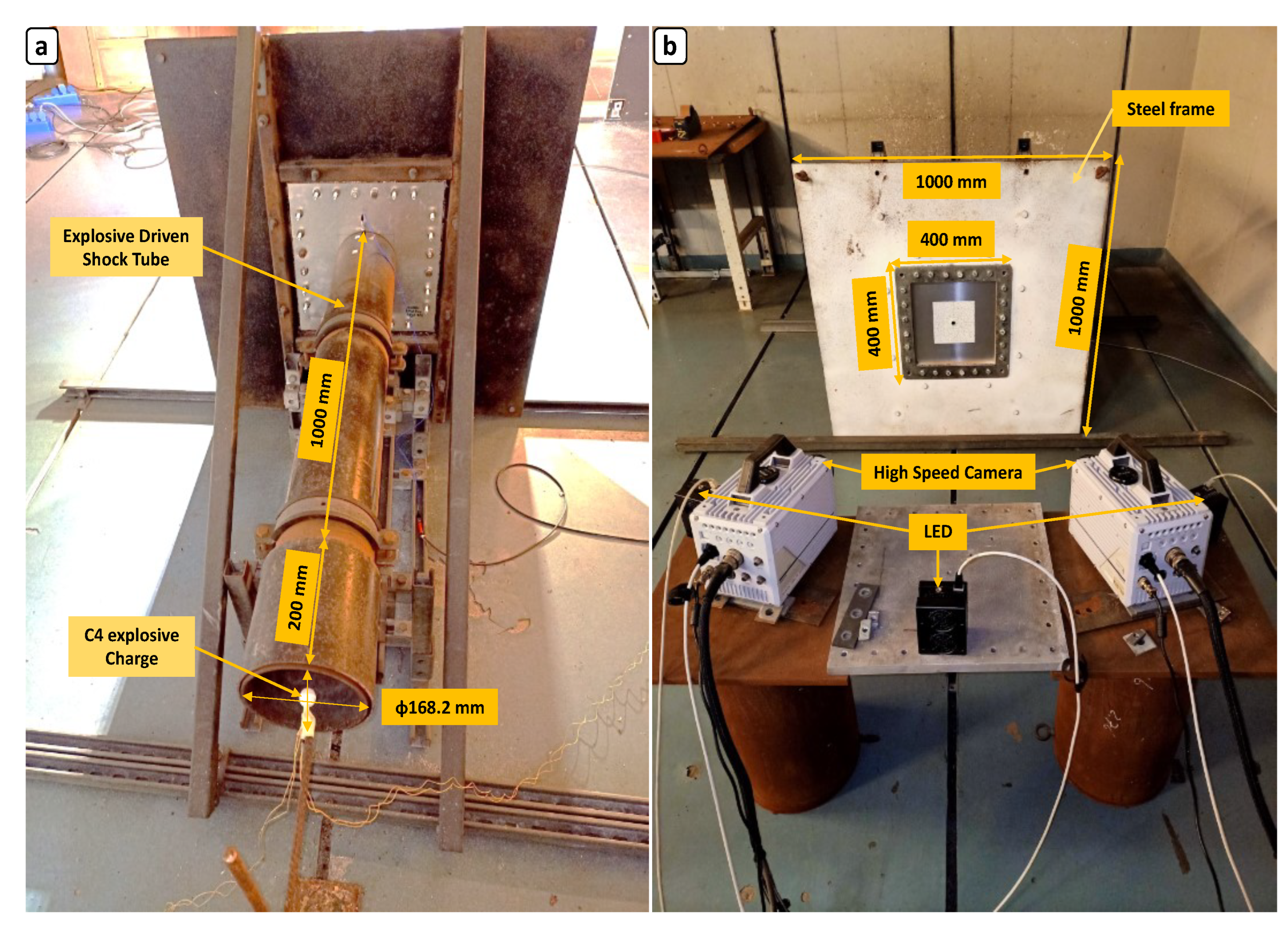
In this section, the aluminum plates after ballistic impact from FSPs (configuration 1 to 4) are exposed to blast loading using an EDST. The evaluation of the performance of this blast loading tool has been reported in previous studies [3,26,27] and is therefore only briefly described in this section. The experimental setup used to study the dynamic response of the blast-loaded plates is shown in Figure 14. It is located at the test bunker of the Propellant, Explosives and Blast Engineering department (PEBE) of the Royal Military Academy. A 10 g C4 explosive charge was placed at the entrance of the EDST. The EDST was built around a 1200 mm long cylindrical steel tube with a wall thickness of 4.5 mm and an inner diameter of 168.2 mm. Figure 14a shows the EDST installed on a steel frame structure with a controlled height from the ground. The center of the tube was set at the same height as the plate center’s point. A high-frequency pressure sensor [28] was mounted at the exit of the inner wall of the tube. It was used to record the incident pressure as well as the arrival time of the blast wave front. At the tube’s exit, a steel frame with dimensions of 1000 mm × 1000 mm × 15 mm was positioned. It was firmly attached to the ground and featured a 300 mm × 300 mm opening as illustrated in Figure 14b. This opening holds the aluminum plate that has already been impacted by the FSPs and will be subjected to the blast loading.
Two similar Photron Fastcam SA5 high-speed digital cameras are positioned at a distance of L 0 equal to 2500 mm from the plate. Alpha defines the angle between the two cameras and measures 39.5 . Three light-emitting diodes were employed to improve the lighting of the aluminum plate and compensate for the lowered aperture of both cameras’ lenses. This was performed to ensure adequate depth of view throughout the experiment because large out-of-plane displacements are foreseen from plate deformation. During plate deformation, synchronized stereo images at a frame rate of 6000 frame per second are captured as soon as the charge detonates. The complete plate behavior is seen throughout the experiments using a field of view of 400 mm × 400 mm and an image size of 512 × 512 pixels.

3.2. Experimental Results

The presentation of the experimental results is divided into two main parts. First, the global response of the blast-loaded target plates subjected to a single FSP impact is presented in Section 3.2.1. Then, the results from tests on blast-loaded plates subjected to three FSP impacts is given in Section 3.2.2. The global response and the damage mechanism are evaluated using DIC.

3.2.1. Blast-Loaded Plates with Single FSP Impact

Figure 15 represents the incident pressures for a 10 g C4 spherical explosive charge mass of three repeated tests as a function of time. No target plate is present at the tube’s exit. The pressure histories were compared for three tests, and small variations in both the overall pressure history and the initial peak pressure were found. An average incident peak pressure of 778 kPa was recorded. The figure shows the setup’s ability to generate a reproducible blast loading on the target plate. Further investigation of the setup’s reproducibility can be found in [3].
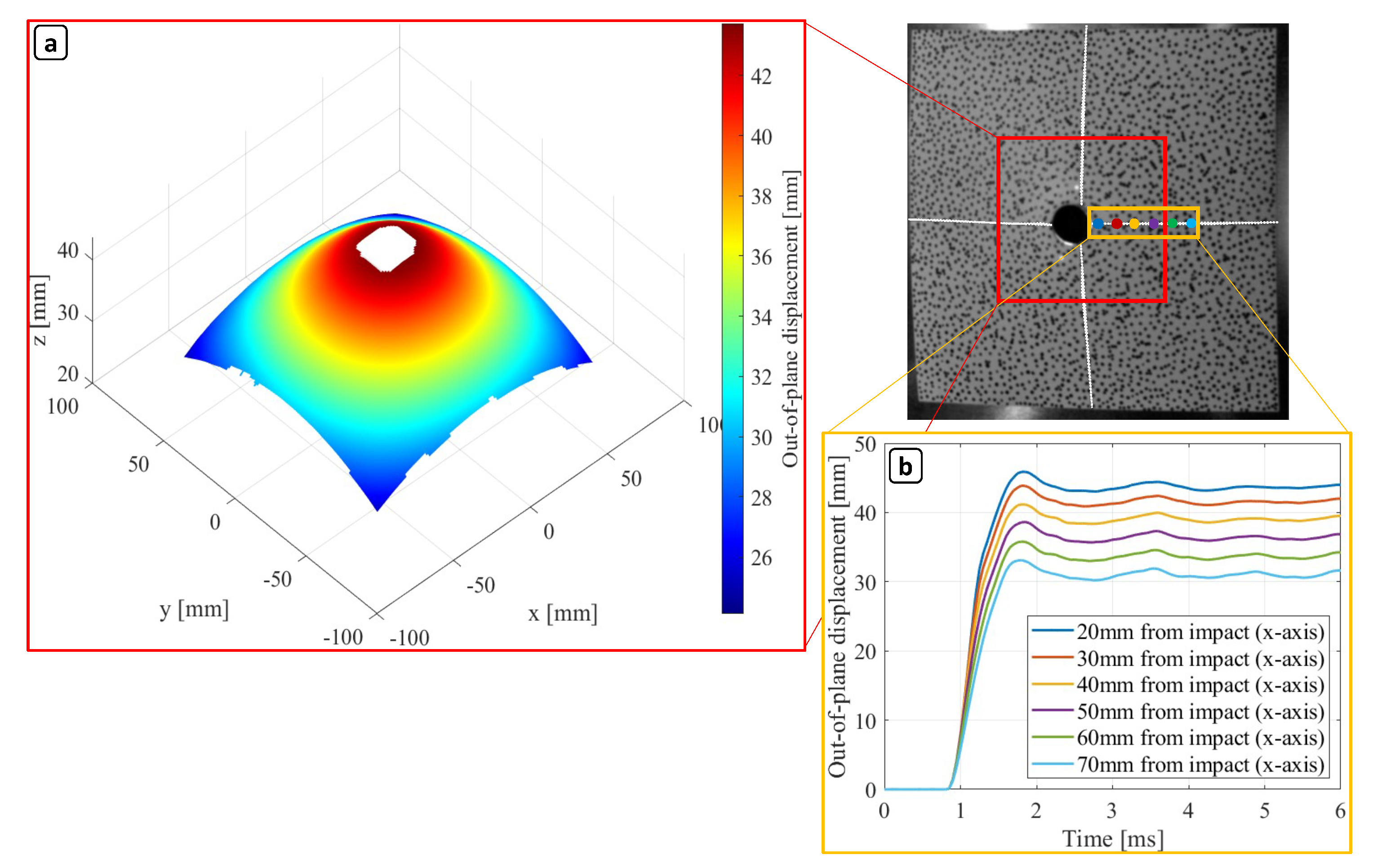
To acquire valid displacement fields from the analysis of the 3D-DIC results, the spray-painted speckle pattern must remain intact throughout the dynamic response of the target plates. Fortunately, only some of the plates experienced a slight detachment around the holes induced by the FSP impact. Moreover, during the deformation process, most images acquired from the high-speed cameras had good visibility and no saturation was recorded due to the fireball resulting from the detonation. As a first observation, none of the three repetitions of the blast-loaded plates in configurations 1 and 2 show any evidence of fracture around the edge of the hole formed by the FSP impact. Figure 16a displays the 3D full-field out-of-plane displacement of the permanent deformation of an aluminum plate under blast loading in configuration 2, which was previously perforated by a single 12.7 mm FSP. The maximum displacement results in a deformation profile resembling a global dome with a superimposed local dome around the center of the plate. The point displacement analysis as a function of time illustrated in Figure 16b reveals that the plate center experiences higher displacement compared to the rest of the plate. The entire plate is deformed, with less marked differences in the out-of-plane displacement of the considered points than in impacts without blast, where the effects are more localized.
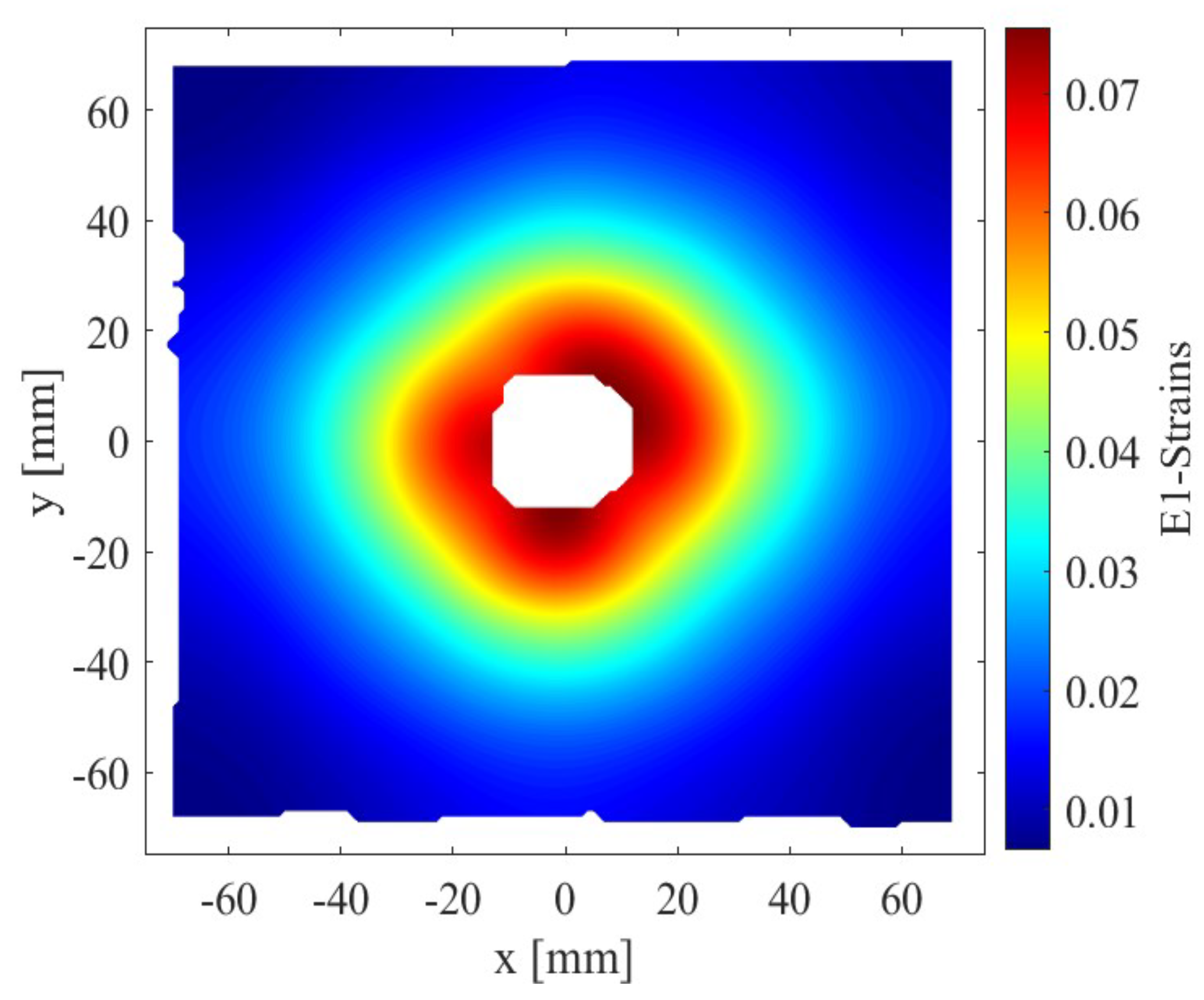
In addition to the analysis of the displacements, the strains are also analyzed and represented in Figure 17. It is found that blast loading creates an elongation of the entire plate with a deformation concentration around the impact hole. As far as the principal direction strains are concerned, they show elongation around the entire hole with the amplitude decreasing as the distance from the center of the hole increases.
In conclusion, our findings indicate that although the influence of an FSP impact was localized around the impact hole, the deformations due to the blast loading are twenty times bigger. After blast loading is applied, a “hole enlargement phenomenon” occurs in the deformed plates and the maximum damage is found when the holes are located in the center of the target. Even when the holes are slightly offset, the blast wave effects and plate displacements are concentrated.

3.2.2. Blast-Loaded Plates with Three FSP Impacts

In this section, a more detailed insight on the response of plates with three FSP impacts is gained by assessing the plates’ shape during deformation. The result of the tests of configurations 3 and 4 are given in Figure 18 and Figure 19. Out of the four blast tests on plates with multiple ballistic impact perforations, only one resulted in cracks and no total fracture was observed. Figure 18 illustrates the result of the permanent deformation and the out-of-plane displacement of tests 2 and 3 of configuration 3. As a first observation, the deformation response is shown to follow trends similar to those previously found in Figure 16. Only slight differences are seen when comparing the deformation profiles at maximum displacement. The findings show that the maximum out-of-plane displacement of blast-loaded plates subjected to a single or three FSP impact are comparable. Therefore, as long as the impacts are located far enough from one another (such as in configuration 3), their locations and their numbers do not influence the dynamic behavior of the blast-loaded specimens.
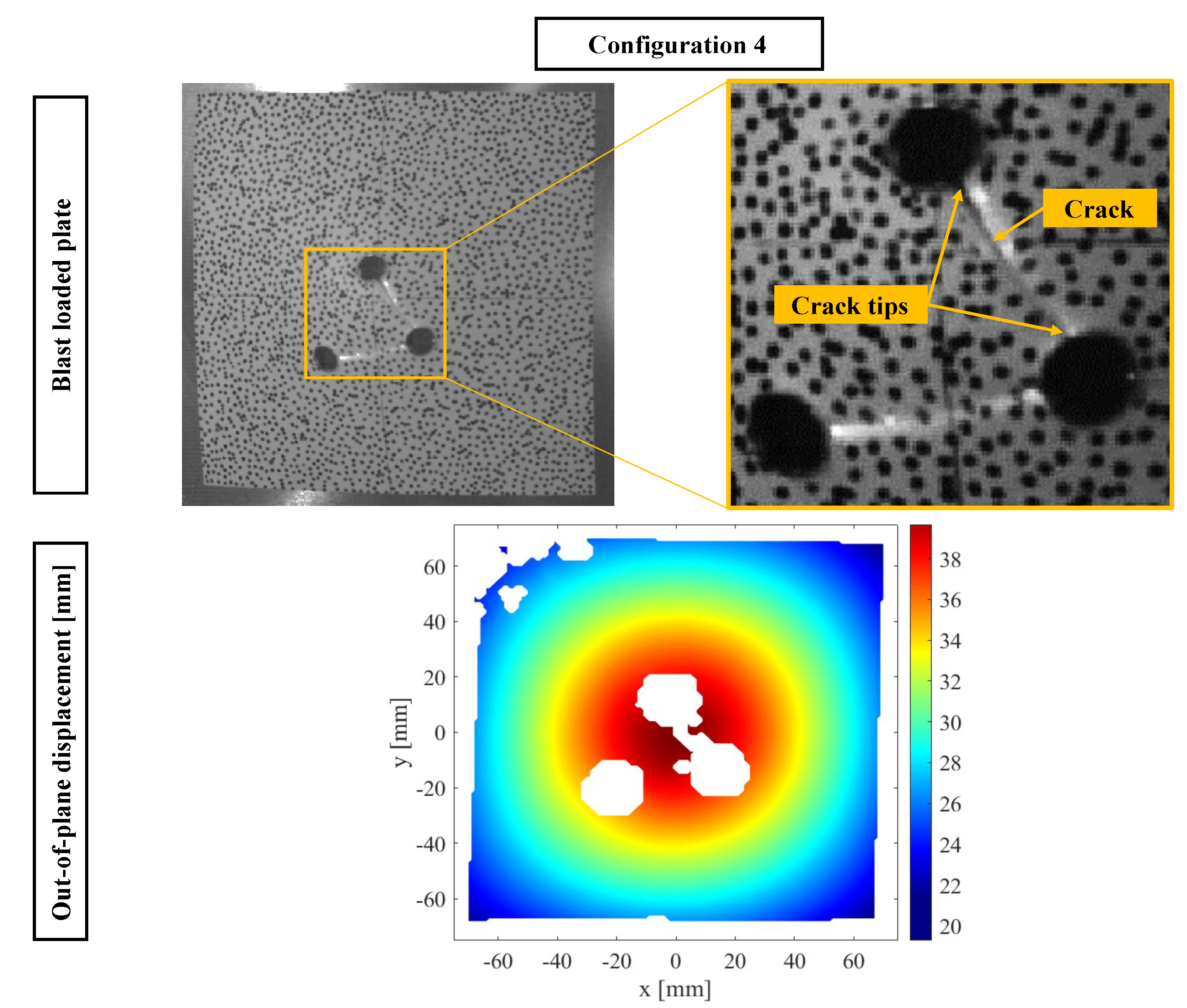
Figure 19 presents an image of the target plate captured by one of the high-speed cameras during testing, showing the damage for configuration 4. A line can be observed between the first and the third impact and a lighter one between the second and third impact. A zoomed-in image of the three enlarged holes highlights the location of crack tips and the crack between the first and the third hole. The crack appears as a discontinuity in the displacement field. It is clear from the DIC results that there is a loss of information between impacts 1 and 3; therefore, the line corresponds to full crack formation on the plate. On the contrary, there is only an initiation of crack formation between impacts 2 and 3.
Because the fireball passes through the perforated hole in the target plate, determining crack propagation within the initial milliseconds following the explosion is challenging. Figure 20 shows high-speed images of the crack propagation. It depicts that the crack initiates at the extremity of the hole created by the first FSP impact and starts to propagate in the direction of the third hole until it reaches its extremity (Video S4). The initiation of crack formation between impacts 2 and 3 is caused by the strain concentration in the area between the two holes as shown in Figure 21. During blast loading, the plate experiences high internal stresses at maximum deformation. The paint coating has elongated more than the plate and was not able to follow the deformation, leading to a reflection of the aluminum underneath the paint. The reflection is captured by the high-speed camera as a lighter line.
Figure 21 provides an illustration of the major principal strains measured by DIC for blast-loaded aluminum plate (configuration 3, test 2 and configuration, 4 test 1). In the figure, a clear zone of strain concentration is visible between impacts 1 and 3 and impacts 2 and 3. Indeed, for the major principal strains, a clear concentration is observed in configuration 4.
In conclusion, if a fracture occurs in the plate, the pre-damage by the FSP impacts influences the global deformation after the blast loading. The experimental findings show that hole spacing has an impact on the plate’s damage mechanism. Blast-loaded plates with smaller hole spacings are more prone to fracture than other configurations.

4. Conclusions

In summary, this study investigates the dynamic behavior of thin aluminum plates subjected to the consecutive loading by fragment impacts and blast waves. To this end, two separate experimental setups were used. The aim of the first step was to examine the influence of projectile diameter, number of impacts, and hole spacing on plate deformation. The digital image correlation technique coupled with high-speed cameras in a stereoscopic setting was used to investigate the out-of-plane displacement and in-plane strain fields. The second step involved the application of a blast load to the perforated plates using an explosive-driven shock tube to investigate the effect of relative hole spacing on the initiation and propagation of cracks in the plates.
The findings of this study indicate that the failure mechanism after single and triple fragment impact is plugging, with localized plastic deformation around the impact point. Larger fragments result in higher out-of-plane displacement and strains, whereas the orientation of the fragment’s front surface influences the major principal strain amplitude. The interaction between strain patterns of each impact increases for closer impact holes. After blast loading, a “hole enlargement phenomenon” is observed, and the maximum damage is found when the holes are centered in the target. Cracks tend to appear in the zones of increased strain between the holes, and the hole spacing significantly affects the damage mechanism. The study confirms the ability of high-speed stereo-vision imaging and digital image correlation to measure out-of-plane displacement and in-plane strain data at high rates, providing researchers with the possibility to study a wide range of dynamic events, including impact, penetration, and blast loading.
The authors recommend expanding the experimental study presented in this paper to include high-velocity impact from fragments with different shapes. The addition of irregularly shaped fragments may yield distinct crack patterns around the perforation holes, which may result in an increased loss of structural integrity of the material under impact loading. To gain a deeper understanding of the behavior of blast-loaded thin metallic plates, it is suggested that detailed numerical simulations of the experiments described in Section 2 and Section 3 should be conducted.

Supplementary Materials

The following supporting information can be downloaded at the following links. Video S1: video of the experimental setup for fragment impact loading using fragment-simulating projectiles. (https://doi.org/10.5281/zenodo.7698649) (accessed on 4 March 2023); Video S2: pitch-angle of FSP before and after ballistic impact on plate captured by high-speed camera 1 (configuration 2) (https://doi.org/10.5281/zenodo.7686272) (accessed on 28 February 2023). Video S3: penetration and perforation process of 12.7 mm FSP on plate captured by high-speed camera 2 (test 2 of configuration 2) (https://doi.org/10.5281/zenodo.7686309) (accessed on 28 February 2023). Video S4: fracture propagation captured by high-speed camera 2 (configuration 4) (https://doi.org/10.5281/zenodo.7686341) (accessed on 28 February 2023).

Author Contributions

Conceptualization, D.L.; methodology, O.A., B.B. and A.A.; investigation, O.A., A.M.; resources, D.L.; data curation, O.A., A.A.; writing—original draft preparation, O.A.; software, O.A.; validation, O.A. and A.M.; supervision, D.L. and L.P. All authors have read and agreed to the published version of the manuscript.

Funding

This research received no external funding.

Institutional Review Board Statement

Not applicable.

Informed Consent Statement

Not applicable.

Data Availability Statement

The data presented in this study are available on request from the corresponding author.

Acknowledgments

The authors are grateful to the staff of the Laboratory of Propellants, Explosives and Blast Engineering (PEBE) department and the Accredited Ballistic Applications Laboratory (ABAL) of the Royal Military Academy (RMA) in Brussels for their support and assistance in performing the different steps of the experimental work. Additionally, the authors would like to extend their appreciation to Quentin Petiqueux for his assistance in data curation.

Conflicts of Interest

The authors declare no conflict of interest.

References

  1. Improvised Explosive Device (IED) Monitor 2021. Available online: https://aoav.org.uk/2022/explosive-violence-monitor-2021/ (accessed on 21 February 2023).
  2. Terrorism Situation and Trend Reports 2022. Available online: https://www.europol.europa.eu/cms/sites/default/files/documents/Tesat_Report_2022_0.pdf (accessed on 21 February 2023).
  3. Atoui, O.; Kechagiadakis, G.; Moumen, A.; Maazoun, A.; Belkassem, B.; Pyl, L.; Lecompte, D. An explosive driven shock tube-based laboratory scale test for combined blast and fragment impact loading. Appl. Sci. 2022, 12, 6854. [Google Scholar] [CrossRef]
  4. Grisaro, H.Y.; Dancygier, A.N. Characteristics of combined blast and fragments loading. Int. J. Impact Eng. 2018, 116, 51–64. [Google Scholar] [CrossRef]
  5. Nyström, U.; Gylltoft, K. Numerical studies of the combined effects of blast and fragment loading. Int. J. Impact Eng. 2009, 36, 995–1005. [Google Scholar] [CrossRef] [Green Version]
  6. Marchand, K.A.; Vargas, M.; Nixon, J.D. The Synergistic Effects of Combined Blast and Fragment Loadings; Technical Report; Southwest Research Institute: San Antonio, TX, USA, 1992. [Google Scholar]
  7. Hyde, D.W. Microcomputer Programs CONWEP and FUNPRO: Fundamentals of Protective Design for Conventional Weapons User’s Guide; Technical Report; Army Engineer Waterways Experiment Station Vicksburg MS Structures Lab: Vicksburg, MS, USA, 1988. [Google Scholar]
  8. Børvik, T.; Dey, S.; Clausen, A. Perforation resistance of five different high-strength steel plates subjected to small-arms projectiles. Int. J. Impact Eng. 2009, 36, 948–964. [Google Scholar] [CrossRef]
  9. Aune, V.; Fagerholt, E.; Hauge, K.O.; Langseth, M.; Børvik, T. Experimental study on the response of thin aluminium and steel plates subjected to airblast loading. Int. J. Impact Eng. 2016, 90, 106–121. [Google Scholar] [CrossRef]
  10. Grisaro, H.Y.; Dancygier, A.N. Representation of damage caused by fragmentation impact in design and analysis of reinforced concrete barriers. Eng. Struct. 2019, 197, 109387. [Google Scholar] [CrossRef]
  11. Osnes, K.; Dey, S.; Hopperstad, O.S.; Børvik, T. On the dynamic response of laminated glass exposed to impact before blast loading. Exp. Mech. 2019, 59, 1033–1046. [Google Scholar] [CrossRef]
  12. Cai, S.; Liu, J.; Zhang, P.; Li, C.; Cheng, Y.; Chen, C. Experimental study on failure mechanisms of sandwich panels with multi-layered aluminum foam/UHMWPE laminate core under combined blast and fragments loading. Thin-Walled Struct. 2021, 159, 107227. [Google Scholar] [CrossRef]
  13. Li, L.; Zhang, Q.C.; Zhang, R.; Wang, X.; Zhao, Z.Y.; He, S.Y.; Han, B.; Lu, T.J. A laboratory experimental technique for simulating combined blast and impact loading. Int. J. Impact Eng. 2019, 134, 103382. [Google Scholar] [CrossRef]
  14. Li, W.; Wang, P.; Feng, G.p.; Lu, Y.g.; Yue, J.z.; Li, H.m. The deformation and failure mechanism of cylindrical shell and square plate with pre-formed holes under blast loading. Def. Technol. 2021, 17, 1143–1159. [Google Scholar] [CrossRef]
  15. Li, Y.; Wu, W.; Zhu, H.; Wu, Z.; Du, Z. The influence of different pre-formed holes on the dynamic response of square plates under air-blast loading. Eng. Fail. Anal. 2017, 78, 122–133. [Google Scholar] [CrossRef]
  16. Granum, H.; Aune, V.; Børvik, T.; Hopperstad, O.S. Effect of heat-treatment on the structural response of blast-loaded aluminium plates with pre-cut slits. Int. J. Impact Eng. 2019, 132, 103306. [Google Scholar] [CrossRef]
  17. Rakvåg, K.G.; Underwood, N.; Schleyer, G.; Børvik, T.; Hopperstad, O.S. Transient pressure loading of clamped metallic plates with pre-formed holes. Int. J. Impact Eng. 2013, 53, 44–55. [Google Scholar] [CrossRef] [Green Version]
  18. Elveli, B.S.; Berstad, T.; Børvik, T.; Aune, V. Performance of thin blast-loaded steel plates after ballistic impact from small-arms projectiles. Int. J. Impact Eng. 2023, 173, 104437. [Google Scholar] [CrossRef]
  19. Aune, V.; Fagerholt, E.; Langseth, M.; Børvik, T. A shock tube facility to generate blast loading on structures. Int. J. Prot. Struct. 2016, 7, 340–366. [Google Scholar] [CrossRef] [Green Version]
  20. Yu, R.; Zhang, Q.; Wei, Z.; Li, L.; Yue, Z.; Wang, X.; Lu, T.J. Dynamic response of fully-clamped steel plate under laboratory-simulated sequential fragment impact and blast loading. Thin-Walled Struct. 2023, 182, 110144. [Google Scholar] [CrossRef]
  21. Ballistic Equipment For Protective Material Testing 2017. Available online: http://www.prototypa.com/file/2522/prototypa-production-protection-2017-02-reduced-quality.pdf (accessed on 21 February 2023).
  22. Ballistic Test Method for Personal Armor Materials and Combat Clothing: STANAG 2920 PPS Edition 2. Available online: http://www.englands1.com/site/wp-content/uploads/8_stanag_2920.pdf (accessed on 13 December 2022).
  23. Moumen, A.; Stirbu, B.; Grossen, J.; Laboureur, D.; Gallant, J.; Hendrick, P. Particle image velocimetry for velocity measurement of muzzle flow: Detailed experimental study. Powder Technol. 2022, 405, 117509. [Google Scholar] [CrossRef]
  24. Louar, M.A. Estimation of the strain rate hardening model parameters of GFRE using blast loads and inverse modelling. Ph.D. Thesis, Vrije Universiteit Brussel, Brussel, Belgium, 2017. [Google Scholar]
  25. Sutton, M.A.; Orteu, J.J.; Schreier, H.W. Image Correlation for Shape, Motion and Deformation Measurements: Basic Concepts, Theory and Applications; Springer: Berlin/Heidelberg, Germany, 2009; p. 321. [Google Scholar] [CrossRef]
  26. Louar, M.A.; Belkassem, B.; Ousji, H.; Spranghers, K.; Kakogiannis, D.; Pyl, L.; Vantomme, J. Explosive driven shock tube loading of aluminium plates: Experimental study. Int. J. Impact Eng. 2015, 86, 111–123. [Google Scholar] [CrossRef]
  27. Ousji, H.; Belkassem, B.; Louar, M.A.; Kakogiannis, D.; Reymen, B.; Pyl, L.; Vantomme, J. Parametric study of an explosive-driven shock tube as blast loading tool. Exp. Tech. 2016, 40, 1307–1325. [Google Scholar] [CrossRef]
  28. PCB Dynamic Pressure Sensors for High Frequency Measurements. Available online: https://www.pcb.com/Contentstore/MktgContent/LinkedDocuments/Pressure/TM-PRS-113B-102B_lowres.pdf (accessed on 21 March 2022).
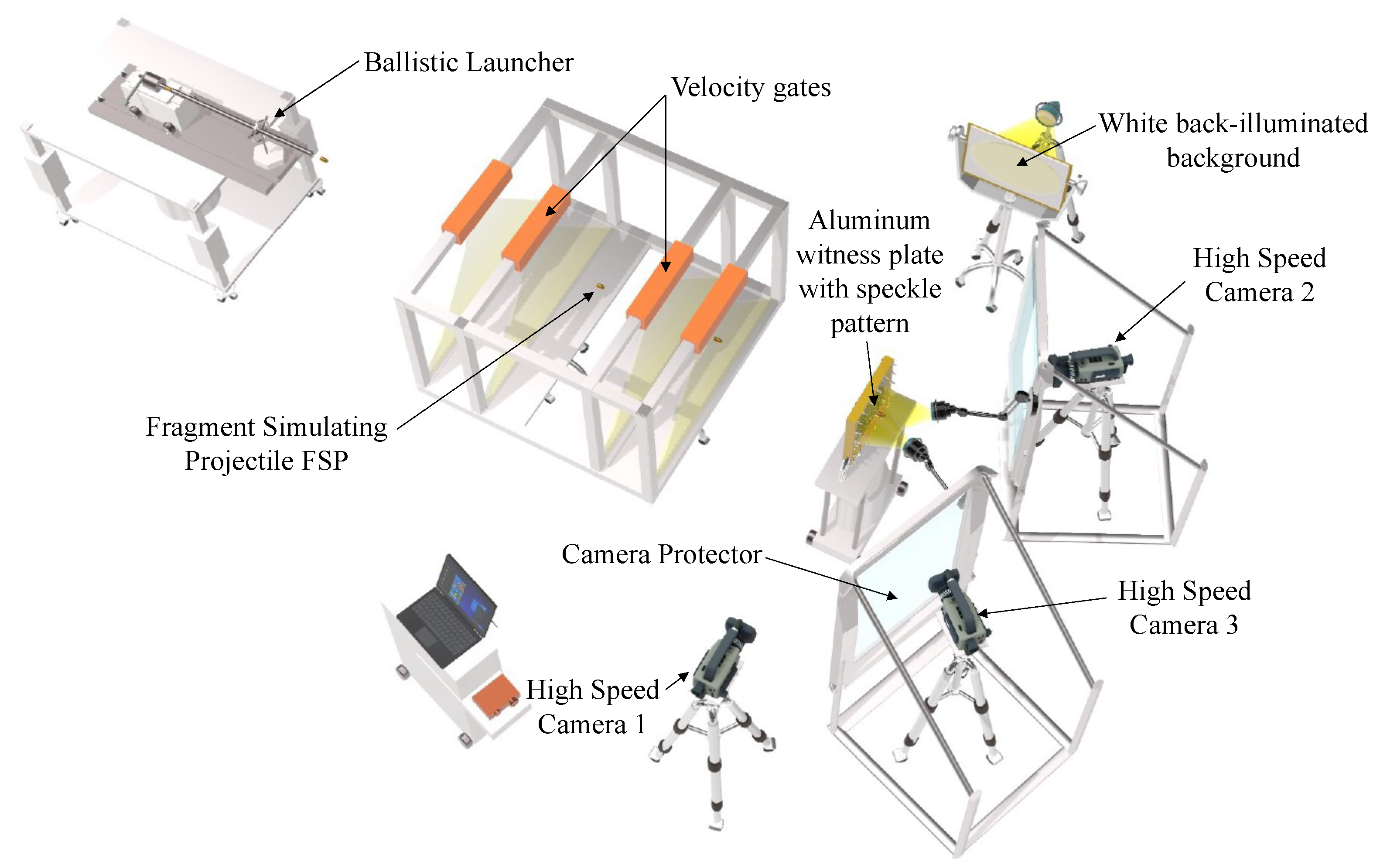
Figure 1. Schematic representation of the experimental setup for fragment impact loading using fragment-simulating projectiles (Video S1).
Applsci 13 03542 g001
Figure 2. Dimensions of the fragment-simulating projectiles and the plate: (a) caliber 7.62 mm [22]; (b) caliber 12.7 mm [22]; (c) aluminum plate specimen with an exposed area of 300 mm × 300 mm and a spray-painted speckle pattern over an area of interest of 150 mm × 150 mm.
Applsci 13 03542 g002
Figure 3. Out-of-plane displacements obtained after DIC calculations (configuration 2) using subset sizes of: (a) 9 and (b) 21.
Applsci 13 03542 g003
Figure 4. Plane view of aluminum plate specimens (configurations 1 and 2) after full FSP perforation.
Applsci 13 03542 g004
Figure 5. (a) Image sequence of the ballistic impact event (configuration 2) captured by high-speed camera 1 at different time steps showing the penetration and the perforation process in the plate: (b) bulge created by the FSP at the rear surface of the plate at the moment of impact, (c) a plug punched through the plate after full perforation and flying together with the FSP.
Applsci 13 03542 g005
Figure 6. High-speed imaging of ballistic impact (configuration 2) on plate target: tracking FSP front surface angle (image 1) and orientation (images 2 to 6) (Video S3).
Applsci 13 03542 g006
Figure 7. Configuration 2, test 2: 3D out-of-plane displacement of aluminum plate showing a local deformation around the impact hole.
Applsci 13 03542 g007
Figure 8. The out-of-plane-displacement of points placed on a circle of a given radius (15 mm, 30 mm or 45 mm) from the impact center as a function of their orientation angle (the 0 angle corresponds to a point placed horizontally at the right side of the impact hole and increases counterclockwise) for the three tests of configurations 1 and 2 and shows the FSP anisotropic effect on plate deformation.
Applsci 13 03542 g008
Figure 9. Comparison between the major principal strain fields of 7.62 mm (left) and 12.7 mm (right) FSP perforation.
Applsci 13 03542 g009
Figure 10. Major principal strains of points placed on a circle of a given radius (15 mm, 30 mm or 45 mm) from the impact center as a function of their orientation angle for the three tests of configuration 2 and shows the influence of FSP orientation at the moment of impact on the amplitude of the major principal strain.
Applsci 13 03542 g010
Figure 11. Plane view of the different tests of configurations 3 and 4 after full FSP perforation and their corresponding out-of-plane displacement fields.
Applsci 13 03542 g011
Figure 12. Comparison between configurations 3 and 4 in terms of the out-of-plane displacement of the geometrical centers of the holes formed by the impact of the three FSPs.
Applsci 13 03542 g012
Figure 13. Comparison between the major principal strain fields of configurations 3 and 4.
Applsci 13 03542 g013
Figure 14. Experimental setup for testing the aluminum plates perforated using fragment-simulating projectiles under blast loading: (a) explosive-driven shock tube dimensions; (b) instrumentation used for the application of the digital image correlation technique.
Applsci 13 03542 g014
Figure 15. Pressure profile recorded by the high-frequency pressure sensor for the explosion of a 10 g C4 charge mass at the entrance of the EDST.
Applsci 13 03542 g015
Figure 16. Configuration 2, test 2: (a) 3D full-field out-of-plane displacement of permanent deformation of blast-loaded aluminum plate previously perforated using a single 12.7 mm FSP; (b) out-of-plane displacement history of different points placed at different distances from the center of the impact on the plate.
Applsci 13 03542 g016
Figure 17. Illustration of the major principal strains for blast-loaded aluminum plate (configuration 2 test 2).
Applsci 13 03542 g017
Figure 18. Plane view of permanent deformation of blast-loaded aluminum plates previously perforated using three 7.62 mm FSPs (tests 2 and 3 of configuration 3). The figure illustrates the full-field displacement of the plates’ centers.
Applsci 13 03542 g018
Figure 19. Image of the final state after blast loading for the plate experiencing cracking (configuration 4). The spray-painted speckle pattern area is shown with a zoom-in on the three enlarged holes. The zoomed image shows the location of crack tips and crack propagation between the first and the third hole. The figure also shows a plane view of the permanent deformation of the blast-loaded aluminum plate.
Applsci 13 03542 g019
Figure 20. High-speed camera images (1–4) capturing the time evolution of fracture propagation in configuration 4.
Applsci 13 03542 g020
Figure 21. Illustration of the major principal strains for blast-loaded aluminum plate (configurations 3 and 4), highlighting strain concentration zones and crack propagation.
Applsci 13 03542 g021
Table 1. Material properties and plate dimensions.
MaterialCompositionDensityYoung’s ModulusPoisson’s RatioPlate Dimensions
[kg/m 3 ][GPa][-][mm × mm × mm]
Al1050 A2710690.33 400 × 400 × 2
Table 2. Tested configurations.
ConfigurationTestNumber of FSPsFSP CaliberImpact Position
[mm][mm, mm]
Test 117.62[17, 10]
Configuration 1Test 2 7.62[7, 21]
Test 3 7.62[−15, −17]
Test 1112.7[−4, 0]
Configuration 2Test 2 12.7[−1, 0]
Test 3 12.7[3, −1]
Test 137.62[20, 55], [38, −11], [−23, −17]
Configuration 3Test 2 7.62[−13, 22], [19, −24], [−43, −11]
Test 3 7.62[−16, 8], [30, −4], [4, −46]
Configuration 4Test 1312.7[−3, 11], [−21, −22], [15, −14]
Disclaimer/Publisher’s Note: The statements, opinions and data contained in all publications are solely those of the individual author(s) and contributor(s) and not of MDPI and/or the editor(s). MDPI and/or the editor(s) disclaim responsibility for any injury to people or property resulting from any ideas, methods, instructions or products referred to in the content.