Abstract
In order to study the damage mechanism of fissure-grouted rocks in abandoned mine pumped storage, uniaxial compression tests were conducted using fissure-grouted rock specimens after dry and wet cycles. Additionally, acoustic emission sensors were used to track the damage of the rock specimens. The results demonstrate a negative correlation between peak strength and elastic modulus and a linear decrease in wave velocity and the mechanical characteristics of the fracture-grouted rock specimens with increasing dry and wet cycles. As the number of dry and wet cycles increased, the deterioration of the fracture-grouted specimens significantly decreased, and the internal microstructural adjustment of the specimens gradually leveled off. A rock constitutive model considering deterioration due to the dry–wet cycle is introduced, and the stress–strain curves under different dry and wet cycles are fitted. The model, which also accurately shows the mechanism of damage to prefabricated fissure-grouted rock specimens after dry and wet cycles, better characterizes the damage development law of prefabricated fissure-grouted rock specimens under the influence of dry and wet cycles.
1. Introduction
In order to increase the capacity of abandoned mine tunnels for storing water, perimeter rock impermeability modification is initially necessary for the development of pumped storage projects in abandoned mines. Moreover, as a result of excavation, support, reciprocal loading, and other unfavorable effects, underground engineering has been disturbed, resulting in an abandoned mine underground space with complex multi-scale, multi-morphic characteristics. In the practice of underground space engineering, fractured rock is a common cleft-rock-bearing state [1,2]. When exploring the storage capacity of the groundwater reservoir after impermeability modification, one cannot avoid studying the effect of water circulation of the fissure-containing grouted rock [3]. A theoretical foundation and key physical and mechanical parameters can be provided by revealing the impact of water on the characteristics of crack-injection rock.
Numerous academics have updated and improved their studies on the impact of dry and wet cycles on the mechanical characteristics of rocks using techniques, such as indoor rock tests [4,5,6,7], microscopic perspective studies [8,9], numerical simulation [10,11,12], and hydration reactions [13,14]. Wang Wei [15], Chai Shaobo [16], and Majeed Y. et al. [17] based on indoor water–rock cycle tests, found that water–rock action leads to a reduction in the compressive strength and elastic parameters of rocks. Verstrynge E. [18], Jian Xiong [19] and Zhanping Song [20] considered changes in the pore structure of shale rock samples under water–rock action from a microscopic point of view, and the structure of large pores in shale increased in complexity after water–rock action. Cuisinier O. [21] and Wang et al. [22] carried out indoor experiments on samples under the action of different wetting–drying cycles and analyzed the effect of a changing number of wetting–drying cycles on the stress–strain relationship of samples. Tanikawa, W. [23] used nitrogen and distilled water as pore fluid to conduct an effective pressure cycling test at room temperature and measured the intrinsic permeability of rocks. Zhe Qin et al. [24] analyzed the changes in rock fine structure by scanning electron microscopy (SEM) to study the fine damage to rocks caused by intrusion of water cycles. In a previous study on fractured rocks [25], it was found that using real rock specimens containing fractures for grouting reinforcement may result in the grouting effect being affected by a variety of factors; this is due to the fact that the damage form of each rock specimen is generally similar, the fracture morphology cannot be accurately controlled. Therefore, this experiment used rock specimens for prefabricated fixed morphological fractures.
In conclusion, specimens of muddy sandstone, used to create the prefabricated fractures, were chosen for the investigation. The fracture specimens were strengthened by grouting, put through several water-immersion test cycles, and then had their mechanical properties tested on rock samples to see how different control groups fared. The aim of this study was to investigate the degradation law of the mechanical properties of specimens of fracture-grouted rock under the influence of water and to expose the deterioration process of such specimens. The findings could serve as a guide for assessing the stability of pumped storage underground reservoir systems in mines and for researching how surrounding rock grouting and underground water infiltration are deteriorating.
2. Materials and Methods
2.1. Materials
Muddy sandstone was chosen for the test. First, the specimen was processed into a standard specimen of size φ50 mm × 100 mm; then, it was processed into a specimen with a single penetration fissure of uniform roughness. Crack size was 20 mm × 2 mm and the angle 45° [26]. The experiment utilized a 1:1 water-to-cement ratio to regulate the cement slurry. Finally, grouting of rock specimens was performed using a triple-integrated grouting performance test device for rock specimens containing cracks [18], as illustrated in Figure 1. Because the lower reservoir of pumped storage needs to undergo dry and wet cycles for a long time, the number of cycles of equal difference can only explore the deterioration of the samples in the early stages of dry and wet cycles, which is not conducive to exploring the overall law. Therefore, this test was divided into 4 groups of control tests according to the number of dry–wet cycles: 0 (whole drying), 5, 10, and 20 times. Each group had five samples for repeat testing in order to increase the reliability of the test results.
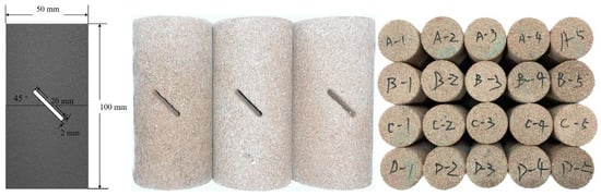
Figure 1.
Schematic representation of the specimen and initial specimen diagram.
2.2. Test Program
The following experimental protocol was developed to investigate the deterioration of fissure-grouted specimens by circulating water. The specific process can be divided into the following five steps (Figure 2 shows the technical route).
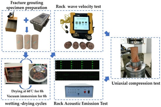
Figure 2.
Test flowchart.
- (1)
- Specimen preparation and maintenance, as outlined in Section 2.1.
- (2)
- Dry and wet cycle specimens: The dry–wet cycle test of rock samples is divided into drying and soaking stage. The soaking stage test is conducted using a homemade immersion bucket and a 2RS-1 vacuum pump, whereas the drying stage test is conducted in an oven. The fissure-grouted rock specimens were treated with 0, 5, 10, and 20 wet and dry cycles. The duration of immersion and drying was chosen to be 8 h to simulate the operation time of pumped storage in abandoned mines [27]. In addition, the tests were conducted using evacuated water immersion and complete drying in an oven to amplify the effect of the wet and dry cycles on the rock specimens. One dry and wet cycle is defined as: the fissure-grouted rock specimen is dried in a constant temperature and humidity oven at 60 °C for 8 h, and then the specimen is placed in an immersion bucket [28,29]. According to GB/T23561.5-2009 [30] preparation for water-filled specimens, a vacuum pump is used to continuously extract the air in the tank for 1 h, and the specimens are soaked for 8 h [31]. The fissure-grouted rock specimen is periodically weighed throughout the soaking stage. When the weight of the sample stops unchanged, the fissure-grouted rock sample is considered saturated with water.
- (3)
- The HC-U81 concrete ultrasonic tester was used to measure the wave velocity of rock specimens following the effects of dry and wet cycles. Wave velocity tests were conducted on specimens with various damage characteristics. Petroleum jelly was applied to the fissure of grouting rock specimen’s surface before measuring the wave velocity to ensure that the metal probe of the wave velocity meter fits snugly against the specimen. The wave velocity of the fracture-grouted rock specimen was measured using the compressional metal probe numerous times. Moreover, the average result was utilized to obtain the final wave velocity measurement.
- (4)
- Rock specimens’ uniaxial compression mechanical characteristics following dry and wet cycles: The device used for the uniaxial compression test is the RMT-150B Rock Mechanics Test System developed by the Wuhan Institute of Geotechnics, Chinese Academy of Sciences. The axial displacement was controlled using the displacement transducer that came with the mechanical test system. Uniaxial compression tests are all loaded in a displacement-controlled manner and continuously loaded until the rock sample is completely destroyed, and the crushed specimens are collected after the experiments are completed.
- (5)
- Rock specimens following dry and wet cycles are tested for acoustic emission: During the uniaxial compression test, the DS5-8B full-information acoustic emission signal analyzer was used to record the acoustic emission signal during the test, with the acquisition threshold set at 40 dB. A full-information acoustic emission signal analyzer is activated after the uniaxial compression starts loading to collect acoustic emission data until the fracture-grouted rock specimens rupture.
2.3. Methods
Reference [32] considered the damage of rock specimens undergoing wet and dry cyclic action. Therefore, the definition of damage variables in this study also includes the initial damage. Drawing on reference [33], a rock damage evolution equation based on the effect of dry and wet cycling was established to define the initial damage value of the fracture-grouted rock after experiencing dry and wet cycling D. The formula is shown as follows:
where: ε is the strain, εd is the peak strain, σd is the peak stress, σc is the damage residual strength, and Dt is the initial damage value of the fissure-grouted rock specimen after experiencing different wetting–drying cycles.
Defining m as the material parameter, the relationship among the internal fractures, grouting material, laminae, anisotropy, and other factors and the mechanical properties of the rock in fissure-grouted rock specimens are considered comprehensively.
According to the principle of rock equivalent effect variation, we obtain the following:
The damage model of the fracture-grouted rock specimen considering the water–rock action is obtained as follows:
3. Results and Discussion
3.1. Wave Velocity Degradation
The rock’s acoustic velocity is a crucial indicator of the engineering rock’s physical and mechanical characteristics, as it is strongly related to the mineral composition, structure, pore space, fracture, stress condition, and others [34]. Sound waves are sent and received using pulse transceivers and probes, and oscilloscopes are used to see waveforms, time, and other information. The upper and lower sides of the test piece for the wave speed test must be uniformly coated with a coupling agent. The acoustic-wave-transmitting and -receiving probes are then positioned on the upper and lower sides of the test piece. The internal structure of the specimen can be evaluated without compromising the specimen’s integrity by measuring the amount of time it takes for the sound wave to travel through the sample. Fissure-grouted rock specimens are susceptible to varying degrees of damage from dry and wet cycles. Moreover, monitoring the wave velocity values can be a quick and easy way to visually assess the interior structural damage of fissure-grouted rock specimens.
Figure 3 displays the wave velocity values for several sets of dry and wet cycles on fracture-grouted rock specimens. The relationship between wave velocity and cycle number variation for fracture-grouted rock specimens after the action of dry and wet cycles was fitted and analyzed following the experimental data obtained from acoustic velocimetry. Moreover, the exponential relationship obtained between the two was very obvious. The fitted relationship equation is as follows:
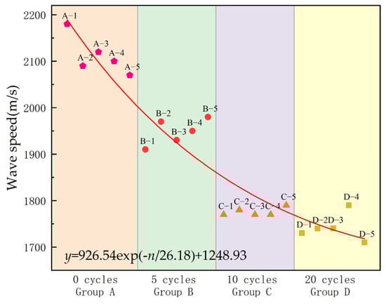
Figure 3.
Wave velocity values of rock specimens of fracture–grouted rock with different groups of wetting–drying cycles.
As the quantity of dry and wet cycle operations increased, the wave velocity values of cracked-grouted rock specimens continuously dropped. The internal structure of the fracture-grouted specimens underwent numerous different alterations as a result of the dry and wet cycles occurring on the specimens. After the first 10 dry and wet cycles of action, the wave velocity rapidly decreases, primarily because of internal microstructural adjustment of the specimen, chemical erosion and dissolution, water swelling, erosion and expansion, and minute particle carryover [35], as shown in Figure 4. At this point, the fluid’s dragging force acting on the particles causes the fracture-grouted rock specimen to dissolve, lubricate, and soften. Hence, the rock sample’s porosity increases quickly, new fractures appear, and the rock-bearing state declines sharply, all of which cause the wave speed value to rapidly decrease. Moreover, after the last 10 wet and dry cycles, the amplitude of the wave velocity decrease in the crack-grouting sample is evidently weakened, and at this time, the microstructure adjustment inside the specimen gradually became smooth. Furthermore, the hydration reaction inside the fissure-grouted specimen gradually ended as well as the full reaction of cement components, and the influence of fluid on the particles became smooth. Then, the specimen entered the stable stage of water swelling, and the water swelling deformation gradually became stable with the growth in the number of cycles [36]. Therefore, at this time, the wave velocity value of fracture-grouted rock specimens shows a trend of slow decrease.
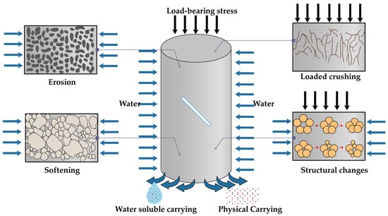
Figure 4.
Coupling damage and pore space changes in fracture-grouted body during wetting–drying cycles.
According to the fitted relationship, the average wave velocity for specimens after 50, 100, 200, and 300 dry and wet cycles is 1386, 1269, 1249, and 1248 m/s, respectively. The impact of dry and wet cycles on fissure-grouted rock specimens decreases with an increase in the number of cycles until it eventually has no effect on the specimens’ quality. Therefore, in this study, the number of dry and wet cycles of rock is mainly set at the stage of severe sample deterioration.
3.2. Degradation of Mechanical Properties of the Specimen
Table 1 displays the mechanical characteristics of the fissure-grouted rock specimens following dry and wet cycling. Figure 5 depicts the stress–strain curves of typical fissure-grouted rock specimens. As can be seen, each rock specimen’s stress–strain curve displays a typical five-stage state.

Table 1.
Mechanical properties of crack-grouting rock specimen under uniaxial compression under wetting–drying cycles.
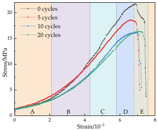
Figure 5.
Stress–strain curves of typical fracture–grouted rock specimens under different numbers of wetting–drying cycles.
Pore-fracture-compacting stage (A section): At the beginning of stressing, the initially opened structural surface or microfractures inside the specimen gradually closes, and the specimen is compacted, resulting in an early nonlinear deformation and an up-concave stress–strain curve.
Stage of elastic deformation (B section): Nearly straight stress–strain curve. The elastic modulus of the fissure-grouted rock specimens is inversely proportional to the number of dry and wet cycles, as shown in the figure, where the slope of the straight line segment drops as the number of dry and wet cycles increases.
Stage of stable crack formation (section C): Although fresh microfractures begin to form inside the specimen and the slope of the stress–strain curve starts to decline with increasing stress, the microfractures are regulated by the applied load and progress in a steady state. The crack begins to steadily grow at the C section stage. The specimen begins to exhibit the expansion phenomenon from the C section as a result of the volume strain curve departing from a straight line and the volume of the inelastic component of the specimen growing.
Cracks in the non-stable development stage (D-segment): The stress–strain curve is upwardly convex, and the formation of microcracks inside the specimen changes qualitatively as they grow until the specimen is entirely destroyed. The radial and volumetric strain rates rise quickly as the specimen’s volume changes from decreasing to grow. At this point, the stress is at its peak. Figure 6 shows the sample failure.
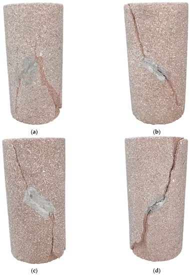
Figure 6.
Failed specimens under different cycles. (a) 0 cycles. (b) 5 cycles. (c) 10 cycles. (d) 20 cycles.
After the specimen reaches its maximum strength, its internal structure is harmed. Fractures in the specimen develop quickly, cross each other, and come together to produce a macroscopic fracture surface, but the specimen essentially stays intact, which is the post-rupture phase (segment E). The bearing capacity of the specimen then rapidly decreases with the increasing strain but does not reach zero, suggesting that the specimen still has some bearing capacity after rupture. The specimen deformation is then mostly expressed as a block slide along the macroscopic fracture surface.
Additionally, the fissure-grouted rock specimens showed a considerable drop in uniaxial compressive strength after performing dry and wet cycles after comparing the uniaxial compressive strength of each specimen. After the initial few dry and wet cycles, this difference in intensity was particularly noticeable. When compared with the elastic modulus of each specimen of fissure-grouted rock in Table 1, the elastic modulus of the specimen lowers when more dry and wet cycles are applied to the specimens. Moreover, the declining trend becomes flat as the number of dry and wet cycles rises, as shown in Figure 7. The elastic modulus of each fissure-grouted rock specimen was calculated using the experimental data from uniaxial compression experiments. The relationship between the elastic modulus En and the number of cycles n of the fissure-grouted rock specimens after water–rock action was then fitted and analyzed. The fitted relationship equation was derived as follows:
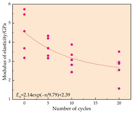
Figure 7.
Modulus of elasticity of fracture–grouted rock specimens under different numbers of wetting–drying cycles and fitting.
This case is consistent with the fracture–grouted rock specimen deterioration described in Section 3.1. The total degree of deterioration in the uniaxial compressive strength and elastic modulus of the fissure–grouted rock specimens steadily increases. Moreover, the stage degradation gradually reduces as the number of dry and wet cycles increases. Comparing the changes in elastic modulus and uniaxial compressive strength, the degradation of the elastic modulus caused by dry and wet cycling is more evident than that of uniaxial compressive strength.
3.3. Specimen Acoustic Emission Characterization
The evolution of crack production, dispersion, extension, and penetration in the rock is found to be correlated with the fluctuation in cumulative ring count [37]. Therefore, the cumulative ringing count is utilized as a starting point to examine how fracture–grouted rock specimens are damaged and destroyed. Figure 8 displays the acoustic emission ring counts and stress curves over time for fracture–grouted rock specimens under uniaxial compression with varying numbers of dry and wet cycles.
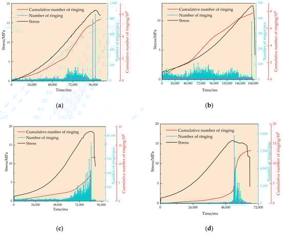
Figure 8.
Acoustic emission characteristics of uniaxial compression of fracture-grouted rock specimens with different numbers of wetting–drying cycles. (a) 0 cycles. (b) 5 cycles. (c) 10 cycles. (d) 20 cycles.
The image illustrates how closely the stress–strain curves of the fracture-grouted rock specimens and the acoustic emission ringing count curves correspond. When the rock sample’s axial stiffness gradually increases, the ringing count decreases and the acoustic emission signal primarily has a low amplitude at the beginning of loading [38]. A minor amount of low-energy acoustic emission is produced during the closing process of the original crack within the fracture-grouted rock specimen, including during the destruction of a portion of the rough surface after closure and the slide between the surfaces of the closed fissures. At this time, the fracture-grouted rock specimen is in the pore-fracture-compacting stage, producing nonlinear deformation. The primary microcracks inside the fissure-grouted rock specimen have essentially closed. The fissure-grouted rock specimen enters the elastic stage with the test loading, and the acoustic emission signal steadily grows and intensifies. When the load steadily grows, cracks start to appear and expand, and the cumulative and auditory emission ringing counts progressively start to be active. As the loading continues, the interaction between cracks begins to intensify, and the microcracks coalesce, penetrate, and gradually form macroscopic cracks [37,39]. Near the stress peak, the acoustic emission activity is exceptionally vigorous, and the acoustic emission ringing count is at its highest.
The overall trend of the cumulative acoustic emission ringing counts of the specimens after 10 and 20 cycles is clearly different from the overall trend of the cumulative acoustic emission ringing counts after 0 and 5 cycles. With an increase in the number of wet and dry cycles, the acoustic emission ringing count peak increases significantly, which makes the cumulative acoustic emission ringing count jump significantly when the fractured-grouted rock specimen is damaged. The dry and wet cycling effect greatly reduces the integrity and stability of the specimen by reducing the fissure-grouted rock specimen. Moreover, the microcracks of the fissure of the grouting rock specimen are more easily sprouted, expanded, lapped, and connected. The continuous wet and dry cycles lead to a gradual increase in microcrack activities within the specimen and a gradual and evident development of damage to the specimen [40].
3.4. Discussion
Equation (1) was used to match the damage–strain curves of fracture-grouted rock specimens during various dry and wet cycles, as shown in Figure 9. The damage growth of fracture-grouted rock specimens tends to slow down as the number of dry and wet cycles rises, which also denotes a change from brittle to ductile rock quality. With the entire process of tight closure of primary cracks in the initial stage of fissure-grouted rock specimens, stable extension of cracks in the elastic stage, and unstable extension of cracks in the elastic–plastic stage to the appearance of macroscopic cracks until damage, the strain–damage relationship of fissure-grouted rock specimens exhibits a good echo of the evolution of damage variables. The time of rapid expansion for damage variables in fracture-grouted rock specimens progresses and the process of damage to the specimens be-comes quick as the number of dry and wet cycles steadily rises. For 20 cycles, the damage of the fracture-grouted rock specimens increased more quickly, with the damage variable rapidly rising to 0.8 at a strain of 0.0075. With five cycles of fracture-grouted rock, the damage growth in rock specimens was slower. The damage progression of the cracked grouted rock specimens in the preceding test section during various dry and wet cycles was verified. The fissure-grouted rock specimen did not tend to be completely damaged because the fissure-grouted rock specimen itself was damaged after the specimen was close to failure, and the higher strength portion of the damage no longer developed.
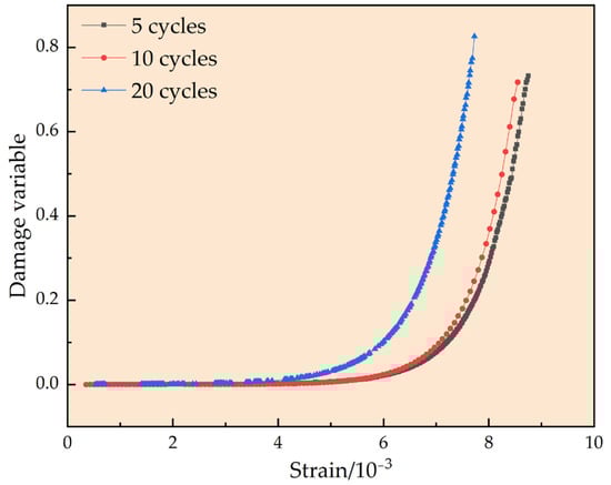
Figure 9.
Strain–damage fitting curves of fracture-containing grouted rock specimens under dry and wet cycles.
Figure 10 shows the theoretical stress–strain curves of fracture-grouted rock specimens with various numbers of dry and wet cycles and test curves in accordance with Equations (5) and (7). The damage model of fracture-grouted rock specimens considering water–rock action indicated in Equation (5) is more logical, as shown by the test curves’ overall agreement with the theoretical curves. After dry and wet cycle action, the model may depict the damage evolution process of fracture-grouted rock specimens.
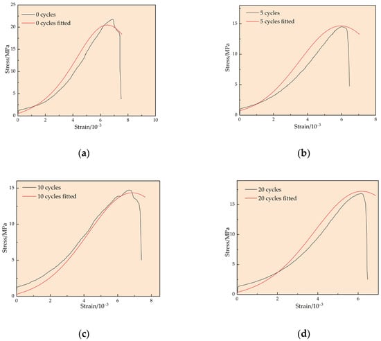
Figure 10.
Theoretical stress–strain curves of fracture-grouted rock specimens with different numbers of dry and wet cycles. (a) 0 cycles. (b) 5 cycles. (c) 10 cycles. (d) 20 cycles.
4. Conclusions
In this study, uniaxial compression tests were conducted on fracture-grouted rock specimens after different numbers of wet and dry cycles by simulating the operation circumstances of the abandoned mine pumped storage. The test was carried out to investigate the rock damage mechanism of the roadway. The mechanical and acoustic properties of the specimens were also analyzed and studied, with three main conclusions:
- (1)
- The wave velocity, peak strength, and elastic modulus of the fissure-grouted rock specimens decrease in a linear connection as a result of wet and dry cycle action on the rock specimens. This linear relationship is negatively connected with the number of wet and dry cycles. Additionally, the reduction rate slows down as the quantity of wet and dry cycles rises, indicating that the impact of wet and dry cycles on specimens of fracture-grouted rock gradually diminishes.
- (2)
- The damage variables after wet and dry cycling can better reflect the damage evolution process of rock specimens after wet and dry cycling; the change in damage variables went through a smooth phase, a slowly increasing phase, and a steeply rising phase, which is consistent with the change law of the stress–strain curve.
- (3)
- A damage intrinsic model for fracture-grouted rock specimens is introduced, considering the impact of wet and dry cycles. The model uses the rock material parameters m to reflect the impact of rock fractures, laminations, anisotropy, and other characteristics on its mechanical properties. The established damage constitutive model can describe the damage characteristics of the surrounding rock of the abandoned mine pumped storage, and can provide a model reference for the understanding of the instability mechanism of the abandoned mine pumped storage.
Author Contributions
All authors contributed to this paper. Conceptualization, B.W. and Q.L.; methodology, Q.F.; validation, B.W., Q.F. and Q.C.; formal analysis, B.W., Q.Y. and Q.C.; investigation, B.W.; writing—original draft preparation, B.W.; writing—review and editing, Q.L.; supervision, Q.L.; funding acquisition, Q.L. All authors have read and agreed to the published version of the manuscript.
Funding
This research was funded by the Institute of Energy, Hefei Comprehensive National Science Center, under Grant (No. 21KZS215), Open Research Grant of Joint National-Local Engineering Research Centre for Safe and Precise Coal Mining (Grant No. EC2021014), 2021 Anhui Province Key Research and Development Program (No. 202104a07020009), and Graduate innovation fund of Anhui University of Science and Technology in 2021 (No. 2021CX2013).
Data Availability Statement
The data used for conducting classifications are available from the corresponding author upon request.
Conflicts of Interest
The authors declare no potential conflict of interest with respect to the research, authorship, and publication of this article.
References
- Sun, Y.; Zhang, P.; Yan, W.; Wu, J.; Yan, F. Grouting Material Development and Dynamic Grouting Test of Broken Rock Mass. J. Mater. Civ. Eng. 2022, 34, 1–15. [Google Scholar] [CrossRef]
- Chen, G.B.; Li, Y.; Li, T.; Zhang, G.H. Mechanical response and deterioration mechanism of sandstone with intermittent joints under drying-saturation circulation. Q. J. Eng. Geol. Hydrogeol. 2023, 56. [Google Scholar] [CrossRef]
- Zhi, G.; Ju, J.; Liu, R.; Yang, R.; Fang, Z.; Zhang, C. Water-rock interaction and its influence on water quality in the underground reservoir. J. Min. Saf. Eng. 2022, 39, 779–785. [Google Scholar] [CrossRef]
- Ma, D.; Miao, X.X.; Chen, Z.Q.; Mao, X.B. Experimental Investigation of Seepage Properties of Fractured Rocks Under Different Confining Pressures. Rock Mech. Rock Eng. 2013, 46, 1135–1144. [Google Scholar] [CrossRef]
- Xing, K.; Zhou, Z.; Yang, H.; Liu, B.C. Macro-meso freeze-thaw damage mechanism of soil-rock mixtures with different rock contents. Int. J. Pavement Eng. 2020, 21, 9–19. [Google Scholar] [CrossRef]
- Vergara, M.R.; Triantafyllidis, T. Influence of Water Content on the Mechanical Properties of an Argillaceous Swelling Rock. Rock Mech. Rock Eng. 2016, 49, 2555–2568. [Google Scholar] [CrossRef]
- Liu, X.; Zeng, W.; Liang, L.; Xiong, J. Prediction of Borehole Wall Collapse Cycle in Longmaxi Shale. Spec. Oil Gas Reserv. 2016, 23, 130–133+157–158. [Google Scholar] [CrossRef]
- Eshiet, K.I.; Sheng, Y.; Ye, J.Q. Microscopic modelling of the hydraulic fracturing process. Environ. Earth Sci. 2013, 68, 1169–1186. [Google Scholar] [CrossRef]
- Yu, L.Q.; Yao, Q.L.; Chong, Z.H.; Li, Y.H.; Xu, Q.; Xie, H.X.; Ye, P.Y. Mechanical and micro-structural damage mechanisms of coal samples treated with dry-wet cycles. Eng. Geol. 2022, 304, 1–14. [Google Scholar] [CrossRef]
- Flukiger, F.; Bernard, D. A new numerical model for pore scale dissolution of calcite due to CO2 saturated water flow in 3D realistic geometry: Principles and first results. Chem. Geol. 2009, 265, 171–180. [Google Scholar] [CrossRef]
- M’Nassri, S.; Lucas, Y.; Schafer, G.; Dridi, L.; Majdoub, R. Coupled hydrogeochemical modelling using KIRMAT to assess water-rock interaction in a saline aquifer in central-eastern Tunisia. Appl. Geochem. 2019, 102, 229–242. [Google Scholar] [CrossRef]
- Wei, S.J.; Tomac, I. Numerical evaluation of Failure Assessment Diagram (FAD) for hydraulic fracture propagation in sandstone. Eng. Fract. Mech. 2022, 263, 1–16. [Google Scholar] [CrossRef]
- Schmalholz, S.M.; Moulas, E.; Plumper, O.; Myasnikov, A.V.; Podladchikov, Y.Y. 2D Hydro-Mechanical-Chemical Modeling of (De)hydration Reactions in Deforming Heterogeneous Rock: The Periclase-Brucite Model Reaction. Geochem. Geophys. Geosyst. 2020, 21, e2020GC009351. [Google Scholar] [CrossRef]
- Uno, M.; Koyanagawa, K.; Kasahara, H.; Okamoto, A.; Tsuchiya, N. Volatile-consuming reactions fracture rocks and self-accelerate fluid flow in the lithosphere. Proc. Natl. Acad. Sci. USA 2022, 119, e2110776118. [Google Scholar] [CrossRef]
- Wang, W.; Gu, F.; He, L.; Liu, Z.; Cao, T.; Li, G. Experimental study on deteriorating characteristics of metamorphic sandstone mechanical parameters under the effect of wetting -drying cycles. J. Water Resour. Water Eng. 2022, 33, 179–185+193. [Google Scholar] [CrossRef]
- Chai, S.; Song, L.; Zhou, W.; Fu, X.; Zhou, Y. Experiment on the Effect of Different Water-Rock Interactions on the Deterioration of Filled Jointed Rock. J. Jilin Univ. 2022, 52, 1–11. [Google Scholar] [CrossRef]
- Majeed, Y.; Abu Bakar, M.Z. Water Saturation Influences on Engineering Properties of Selected Sedimentary Rocks of Pakistan. J. Min. Sci. 2018, 54, 914–930. [Google Scholar] [CrossRef]
- Verstrynge, E.; Adriaens, R.; Elsen, J.; Van Balen, K. Multi-scale analysis on the influence of moisture on the mechanical behavior of ferruginous sandstone. Constr. Build. Mater. 2014, 54, 78–90. [Google Scholar] [CrossRef]
- Xiong, J.; Li, Y.; Liu, X.; Liang, L.; Ding, Y.; Hou, L. Influences of water–rock interaction on the physical and mechanical properties of shales: A case study of the Lower Silurian Longmaxi Formation in the Sichuan Basin. Nat. Gas Ind. 2022, 42, 190–201. [Google Scholar] [CrossRef]
- Song, Z.; Cheng, Y.; Yang, T.; Huo, R.; Wang, J.; Liu, X. Experimental study of the influence of osmotic pressure on pore structure evolution in limestone. Rock Soil Mech. 2019, 40, 4607–4619+4643. [Google Scholar] [CrossRef]
- Cuisinier, O.; Masrouri, F.; Mehenni, A. Alteration of the Hydromechanical Performances of a Stabilized Compacted Soil Exposed to Successive Wetting-Drying Cycles. J. Mater. Civ. Eng. 2020, 32, 1–9. [Google Scholar] [CrossRef]
- Wang, J.; Liu, M.; Qiu, Z.; Zhang, H.; Bai, J. Effects of Wetting–Drying Cycles on Strain–Stress Relationship from Triaxial Test of a Mudstone Mixture. Geotech. Geol. Eng. 2019, 37, 1039–1045. [Google Scholar] [CrossRef]
- Tanikawa, W.; Shimamoto, T. Comparison of Klinkenberg-corrected gas permeability and water permeability in sedimentary rocks. Int. J. Rock Mech. Min. Sci. 2009, 46, 229–238. [Google Scholar] [CrossRef]
- Qin, Z.; Fu, H.; Chen, X. A study on altered granite meso-damage mechanisms due to water invasion-water loss cycles. Environ. Earth Sci. 2019, 78, 428. [Google Scholar] [CrossRef]
- Liu, Q.; Wu, B.; Fu, Q.; Chen, Q.; Liu, F. New Testing Device for the Grouting Reinforcement Performance of Fractured Rocks. J. Eng. Sci. Technol. Rev. 2022, 15, 168–176. [Google Scholar] [CrossRef]
- Zhang, J.; Xu, R.; Liu, Y.; Zhang, H.; Qing, X.; Chen, M. Experimental study on mechanical properties of grouted fractured rock mass under freeze-thaw cycles. J. Exp. Mech. 2021, 36, 378–388. [Google Scholar] [CrossRef]
- Zheng, H.; Zhang, Z.; Wu, H.; Lei, X. Study on the daily optimized dispatching and economic operation of cascade pumping stations in water conveyance system. J. Hydraul. Eng. 2016, 47, 1558–1565. [Google Scholar] [CrossRef]
- Xu, J.; Li, Y.; Ren, C.; Lan, W. Damage of saline intact loess after dry-wet and its interpretation based on SEM and NMR. Soils Found. 2020, 60, 911–928. [Google Scholar] [CrossRef]
- Zhang, F.; Jiang, A.; Yang, X. Shear creep experiments and modeling of granite under dry-wet cycling. Bull. Eng. Geol. Environ. 2021, 80, 5897–5908. [Google Scholar] [CrossRef]
- GB/T 23561.5-2009; Methods for Determining the Physical and Mechanical Properties of Coal and Rock. The National Standard Compilation Groups of People’s Republic of China: Beijing, China, 2009. (In Chinese)
- Chai, S.; Zhang, L. Study on damage mechanism of alkali activated fly ash mineral powder modified expansive soil under drying wetting freezing thawing cycles. Eng. Mech. 2023, 40, 1–12. [Google Scholar] [CrossRef]
- Fu, P.; Qi, X.; Wang, S.; Geng, D.; Ke, T. Study on damage law of layered composite rock after high temperature. J. Archit. Civ. Eng. 2022, 40, 1–13. Available online: https://kns.cnki.net/kcms/detail/61.1442.tu.20221108.0927.002.html (accessed on 13 February 2023).
- Liu, J.; Zhu, X.; Xu, L.; Zhang, S. Study on Damage Evolution Law of Granite after High Temperature Cooling. Coal Technol. 2021, 40, 30–33. [Google Scholar] [CrossRef]
- Wang, R.; Ren, M.; Liu, J.; Zhao, L.; Xu, S.; Shi, T. Study on Correlation Between Rock Wave Velocity and Strength Parameters. Min. Res. Dev. 2021, 41, 87–91. [Google Scholar] [CrossRef]
- Zhang, C.; Song, Z.; Zhao, Y.; Han, P.; Teng, T. DEM-CFD coupling analysis of broken rock mass movement in underground reservoir of coal mine. J. Min. Strat. Control. Eng. 2021, 3, 85–95. [Google Scholar] [CrossRef]
- Zhang, Z. Study on the Characteristics of Swelling-Creep and Damage of Soft Rock under Hydration; Hunan University of Science and Technology: Xiangtan, China, 2018. [Google Scholar]
- Zhang, H.; Guo, J.; Sun, F.; Shi, X.; Zhu, Z. Acoustic Emission and Fracture Evolution Characteristics of Granite under Different Testing and Moisture Conditions. Chin. J. High Press. Phys. 2022, 36, 77–91. [Google Scholar] [CrossRef]
- Chen, D.; Ji, H.; Fu, Z. Evaluation Method of Crack Initiation Stress in Brittle Rocks Based on Acoustic Emission b-Value Evolution. Met. Mine 2022, 52, 1–12. Available online: https://kns.cnki.net/kcms/detail/34.1055.TD.20221021.1752.004.html (accessed on 13 February 2023).
- Liu, B.; Huang, J.; Wang, Z.; Liu, L. Study on Damage Evolution and Acoustic Emission Character of Coal-rock Under Uniaxial Compression. Chin. J. Rock Mech. Eng. 2009, 28, 3234–3238. [Google Scholar]
- Yang, K.; Zhang, Z.-N.; Chi, X.-L.; Lyu, X.; Wei, Z.; Liu, W.-J. Experimental study on crack evolution and damage characteristics of water bearing sandstone under cyclic loading. Rock Soil Mech. 2022, 43, 1791–1802. [Google Scholar] [CrossRef]


Disclaimer/Publisher’s Note: The statements, opinions and data contained in all publications are solely those of the individual author(s) and contributor(s) and not of MDPI and/or the editor(s). MDPI and/or the editor(s) disclaim responsibility for any injury to people or property resulting from any ideas, methods, instructions or products referred to in the content. |
© 2023 by the authors. Licensee MDPI, Basel, Switzerland. This article is an open access article distributed under the terms and conditions of the Creative Commons Attribution (CC BY) license (https://creativecommons.org/licenses/by/4.0/).