Abstract
Due to the rapid growth in the global volume of data, deoxyribonucleic acid (DNA) data storage has emerged. Error correction in DNA data storage is a key part of this storage technology. In this paper, an improved marker code scheme is proposed to correct insertion, deletion, and substitution errors in deoxyribonucleic acid (DNA) data storage. To correct synchronization (i.e., insertion and deletion) errors, a novel base-symbol-based synchronization algorithm is proposed and used. In the improved scheme, the marker bits are encoded as the information part of the LDPC code, and then mapped into marker bases to correct the synchronization errors. Thus marker bits not only assist in regaining synchronization, but also play a role in LDPC decoding to improve decoding performance. An improved low-complexity normalized min-sum (INMS) algorithm is proposed to correct residual substitution errors after regaining synchronization. The simulation results demonstrate that the improved scheme provides a substantial performance improvement over the concatenated marker code scheme and concatenated watermark code scheme. At the same time, the complexity of the INMS algorithm was reduced, while its bit error rate (BER) performance was approximate to that of the belief propagation (BP) algorithm.
1. Introduction
In the Big Data era, a huge amount of data is generated every day. It is predicted that the global data volume will reach 175 ZB by 2025 [1,2], and the data volume will exceed the storage capacity. Therefore, there is an urgent need to find new storage media. The possibility of storing data in DNA was first proposed by Clelland in 1999 [3]. Due to its durability and ultrahigh density, DNA is a great potential storage medium. One gram of DNA can store 215 GB of data, and the data stored in DNA can be preserved for tens of thousands of years [4]. Therefore, DNA data storage has attracted considerable attention from the data storage community in recent years, especially in the area of cold data storage, such as government documents and historical archives [5].
Channel error correction is a key part of DNA storage technology. In DNA synthesis and sequencing, insertion, deletion, and substitution errors of nucleotide bases occur [6]. Since DNA molecules use four nucleotide bases (i.e., adenine (A), thymine (T), cytosine (C), and guanine (G)) to store genetic information [7], DNA is a quadratic channel corrupted by insertions, deletions, and substitutions. To correct synchronization (i.e., insertion and deletion) errors, Matthew C. Davey proposed the concatenated watermark code scheme [8], and Daniel Marco proposed the concatenated marker code scheme [9]. To correct DNA channel errors, a modified concatenated watermark code scheme and a modified concatenated marker code scheme were proposed in [10,11], respectively. The former uses watermark codes as inner codes and low-density parity-check (LDPC) codes [12] as outer codes. The latter employs the marker codes as inner codes and LDPC codes as outer codes. In these schemes, watermark and marker codes only assist in regaining synchronization, and they play no role in LDPC decoding. Therefore, these schemes have the disadvantage in error correction performance.To improve error correction performance, we designed an improved error correction scheme for DNA data storage.
In Ref. [13], a novel marker code scheme, called the embedded marker code scheme, was proposed for channels corrupted by insertions, deletions, and additive white Gaussian noise (AWGN), which are binary channels. On the basis of the embedded marker code scheme, we propose an improved scheme for DNA channels. In the improved scheme, marker codes are used as inner codes and LDPC codes are used as outer codes. Marker bits are encoded as part of the information bits. Compared to the concatenated marker code scheme, marker bits in the proposed scheme additionally assist in LDPC decoding. To correct synchronization errors, a base maximal a posteriori (MAP) detector was adopted. Correspondingly, a novel base-symbol-based synchronization algorithm is provided for the detector. In LDPC decoding, we propose an improved normalized min–sum (INMS) algorithm to reduce decoding complexity. There were some biological constraints on DNA synthesis and sequencing that needed to be considered in our proposed scheme. The long nucleotide chains cannot be synthesized in modern DNA synthesis technology, and the maximal length of nucleotides is 250 [14]. To maintain stability, the GC content of the synthesized sequence must be close to 50% (i.e., 40∼60%) [15].
Our main contributions are summarized as follows.
- We propose an improved marker code scheme for DNA channels based on the embedded marker code scheme. In this scheme, a novel base-symbol-based synchronization algorithm is proposed to correct synchronization errors.
- In LDPC decoding, we propose an improved decoding algorithm to reduce decoding complexity.
The paper is organized as follows. In Section 2, the DNA channel model is described. In Section 3, related works are introduced. In Section 4, the improved marker code scheme’s development is presented. In Section 5, the base-symbol-based synchronization and the low-complexity INMS algorithms are outlined. Section 6 shows the simulation results. Lastly, Section 7 concludes the paper.
2. DNA Channel Model
Insertion and deletion errors occur mainly during DNA synthesis, and substitution errors occur mainly in DNA sequencing [16]. Thus, the error probability is influenced by synthesis and sequencing techniques. Nanopore and Illumina sequencing are advanced sequencing methods. Compared with nanopore sequencing, Illumina sequencing has the advantage of high reading accuracy, i.e., Illumina sequencing has lower probabilities of base insertion, deletion, and substitution errors. In this paper, we used a channel model on the basis of Illumina sequencing [17], as shown in Figure 1.
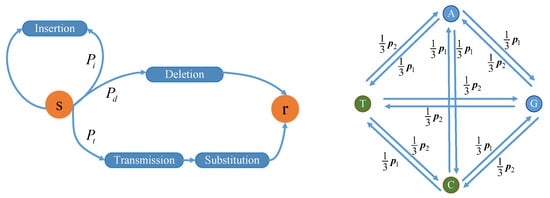
Figure 1.
DNA channel model based on Illumina sequencing. s, input base; r, output base.
In Figure 1, the channel input is a nucleotide base (corresponding to s). Let the maximal insertion length be . With probability , the insertion event occurs, i.e., one or two bases are inserted in the input base where the length of the inserted bases obeys a geometric distribution. With probability , the deletion event occurs, which means that the input base is deleted. With probability , the input base is transmitted, i.e., no insertion or deletion event occurs, but the substitution error may occur according to the transfer probabilities among bases. Let be the parameter related to the sequencing; then, and are satisfied, where [17]. The substitution error probabilities for T and G are higher than those for A and C. In a word, the input base may be corrupted by insertion, deletion, and substitution errors. Therefore, the channel output is zero, one, or two nucleotide base(s) (corresponding to r in Figure 1). Generally, input data are a base sequence consisting of many bases, and the bases enter the channel one by one.
3. Related Works
In the latest related works [10,11], two error correction schemes were used to correct insertion, deletion, and substitution errors in DNA channels, including the concatenated watermark code [10] and the concatenated marker code scheme [11]. We introduce these schemes in this section.
3.1. Concatenated Watermark Code Scheme
The procedure of the concatenated watermark code scheme is illustrated in Figure 2a. The LDPC code was sparsified to obtain sparse code word s (in which 0 is much more than 1); then, s was superposed with the watermark code to obtain the bias sequence. The watermark code, which is a fixed pseudorandom sequence, is known to the receiver. The principle of this scheme is that the receiver exploits a known watermark code to regain synchronization for error correction. More details about encoding and decoding are in [10].
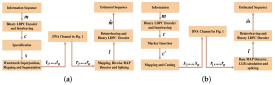
Figure 2.
The procedure of the concatenated watermark code scheme and the concatenated marker code scheme. (a) Concatenated watermark code scheme; (b) Concatenated marker code scheme.
The storage efficiency of this scheme can be expressed as follows:
where denotes the code rate of the LDPC code, and denotes the sparsification efficiency. For example, if 4 bits are converted into 5 bits in the sparsification, then .
3.2. Concatenated Marker Code Scheme
The procedure of the concatenated marker code scheme is shown in Figure 2b. In this scheme, marker codes (known by the receiver) are inserted uniformly (i.e., equally spaced between any two marker codes) in LDPC code word c. Information-carrying sections of the code are interspersed with synchronization-providing marker sections. Similar to the watermark code, the marker code serves to regain synchronization in decoding. In fact, marker codes can be considered irregular watermark codes [8]. Compared with concatenated watermark code schemes, concatenated marker code schemes can provide better synchronization performance [8]. More details about this scheme are found in [4].
In this scheme, the storage efficiency can be expressed as follows:
where denotes the interval between two adjacent marker codes, and denotes the length of the marker codes.
4. Improved Marker Code Scheme
The procedure of the improved marker code scheme is shown in Figure 3. The encoding process is shown in Figure 4. First, binary sequence , including information bits and marker bits, is encoded as the information part of the LDPC code. Then, the LDPC code is interleaved to obtain the codeword . Second, sequence is arranged to guarantee that the marker bits are uniformly distributed. In other words, marker bits are placed at each interval . Next, the arranged sequence is mapped into a nucleotide sequence and cut into several short nucleotide chains because DNA long chains are difficult to synthesize. Lastly, sequences enter the channel and correspondingly output sequences .
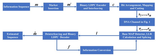
Figure 3.
The procedure of the improved marker code scheme.
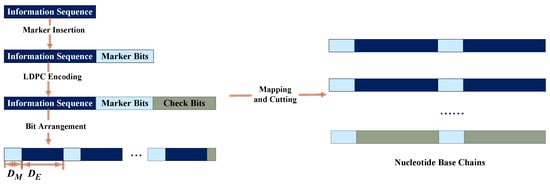
Figure 4.
The encoding process of the improved marker code scheme.
Due to synchronization errors in a DNA channel, the first step in decoding is to regain synchronization. This step is performed in the base MAP detector, where a new base-symbol-based synchronization algorithm is used. The details of this algorithm are described in the next section. The base detector outputs several log-likelihood ratio (LLR) sequences; then, these sequences are spliced together to obtain a new LLR sequence, . The LDPC decoder receives sequence and corrects residual substitution errors. To further improve correction performance, the LDPC code decoder feeds back information to the detector for resynchronization. The error correction performance is improved with the joint decoding between the detector and the LDPC decoder.
Let the code length of the LDPC code be N, and the check bit length of the LDPC code be M. If N can be divided by , the storage efficiency of the improved marker code scheme can be expressed as follows:
If N cannot divided by , the storage efficiency is expressed as follows:
Thus, the storage efficiency of this scheme is expressed as follows:
Compared to the concatenated marker code scheme, in the proposed scheme, marker bits are inserted before LDPC encoding, which means that the marker codes are part of the LDPC code. Therefore, marker codes in the proposed scheme not only assist in regaining synchronization, but also improve the decoding performance of the LDPC code.
5. Decoding Algorithm
5.1. Base-Symbol-Based Synchronization Algorithm
A conventional forward/backward (FB) algorithm is usually used to correct the synchronization errors [8,9,10,11]. A novel base-symbol-based synchronization (i.e., FB) algorithm is proposed and used to regain synchronization in the improved scheme.
In this subsection, we describe the algorithm in the case of the maximal insertion length (of the channel) . Suppose that channel input sequence and output sequence . These are both nucleotide base sequences, but their lengths, T and Q, may be different. Let the position offset be , if the -th base of the output sequence corresponds to the k-th base of the input sequence. Let be the maximal allowed position offset. Thus, . Sequence forms the hidden states of the hidden Markov model. To express the transfer probabilities among the bases, we define the following function:
- if ,
- if ,
As in [8], we define the coefficients as follows:
where and . These coefficients can be obtained with forward and backward recursion. Suppose ; thus, the transfer probabilities between two adjacent hidden states are , , , , , and . For example, the transfer probability from state to state is ; thus, the probability of conversion from to is . Suppose
The calculations are given as follows.
The probabilities of certain states can be derived after recurring all coefficients. In other words, the a posteriori probabilities of the channel input bases can be obtained and expressed as follows:
The a posteriori probabilities of the bases need to be converted into the soft information of bits (which is the input of the binary LDPC decoder). Since 2 bits are mapped into 1 base, there are 24 mapping rules between base symbols and bits. Suppose that the mapping rule (00-A, 01-C, 10-T, 11-G) is adopted. The first bit is defined as the low bit, and the second bit is defined as the high bit. Thus, several low and high bits form the channel input sequence. For nonmarker bits, the LLRs of the low bits are calculated as follows:
The LLRs of the high bits are calculated as follows:
For marker bits, the LLRs of the low and high bits are set to the larger absolute values because the positions and values of the marker bits are known to the decoder. If the marker bit is 1, the LLR is positive. If the marker bit is 0, the LLR is negative. Through the above method, an LLR sequence is obtained; then, passes to the decoder. Lastly, the LDPC decoder outputs the estimated sequence , as shown in Figure 3.
The joint decoding between decoder and detector is achieved with information feedback. In the LDPC decoder, let be the LLR sequence used for hard decisions. Thus, the feedback LLR sequence . Suppose that the LLRs of the low bits are , and those of the high bits are . Thus, the a priori probabilities (which are used for the base MAP detector in the next synchronization) of the nonmarker bases are updated as follows:
The a priori probabilities of the marker bits are determined and fixed to large absolute values in decoding (i.e., they are unchanged even at resynchronization).
Every time the detector is used, the number of synchronizations is increased by 1. There is an upper limit to the number of synchronizations (joint decoding) that is predetermined. Let this upper limit be . In the first synchronization, the a priori probabilities of the nonmarker bases used by the detector are initialized to , , , . In the second and subsequent synchronizations, the a priori probabilities of the nonmarker bases are calculated with (18)–(21).
5.2. Low-Complexity INMS
5.2.1. INMS
In related works, the belief propagation (BP) algorithm was used to correct residual substitution errors after regaining synchronization [10,11]. However, the BP algorithm has high complexity [18]. To reduce decoding complexity, we propose an improved decoding algorithm for our proposed scheme called INMS.
Notations in the algorithm development are as follows: k denotes the length of the information bits, n denotes code length, denotes the correction factor, denotes the initial LLR of the j-th bit, denotes the total LLR, denotes the maximal number of the iterations, M denotes the set of all marker bits, denotes the set of all check nodes connected with the j-th bit, denotes the set of all variable nodes connected with the i-th check node, denotes except for the i-th check node, and denotes except for the j-th variable node. The detailed procedure of the INMS algorithm is given in Algorithm 1.
In Algorithm 1, marker bits are fixed; thus, their , , and are not calculated because the marker bits are known to the decoder. Therefore, marker bit nodes reduce decoding complexity while providing reliable information to other nodes.
| Algorithm 1 INMS for the binary LDPC code decoder. |
|
5.2.2. Algorithm Complexity
In this subsubsection, we give the quantitative analysis of algorithm complexity. A regular LDPC code was used for the analysis that had a length of N, a code rate of 0.5, a row weight of R, and a column weight of C. We defined the complexity of an addition operation as , the complexity of a multiplication operation as , and the complexity of a table lookup operation as . Table 1 shows the complexity of the BP, NMS (i.e., normalized min-sum algorithm), and INMS algorithms. The INMS algorithm was divided into four steps: syndrome calculation, check node update, variable node update, and verdict LLR update. In syndrome calculation, three algorithms have the same complexity, . In the check node update, the INMS algorithm reduces the table lookup operation compared to the BP algorithm, and reduces the complexity of compared to the NMS algorithm. In variable node update, the complexity of the INMS algorithm is reduced by compared to that with the BP and NMS algorithms. In verdict LLR update, the complexity of the INMS algorithm is reduced by compared to that with the BP and NMS algorithms. Compared to the BP algorithm, the total complexity of the INMS algorithm is reduced by . Therefore, the INMS algorithm could achieve improved complexity.

Table 1.
Algorithm complexity comparison.
6. Simulation Results
In this section, we compared the error correction performance of the proposed scheme, concatenated watermark code scheme, and concatenated marker code scheme. Moreover, we compared the decoding performance of the proposed INMS algorithm to that of the flooding BP algorithm. We used Microsoft Visual Studio 2019 as the simulation platform.
To ensure fairness, three schemes were compared at equal levels of storage efficiency. At any same storage efficiency, the comparison was valid. In our simulations, we compared the bit error rate (BER) performance of the schemes at a storage efficiency of 0.72 (which was determined with LDPC code rates , , and ). A quasicyclic LDPC code with code length of 4544 and code rate of 0.9 was used. In the proposed scheme, suppose that and (which makes the storage efficiency be 0.72). To guarantee the balance of GC content, and were selected as the marker bases. In other words, the nucleotide base sequences contained two types of markers, and . Since it is difficult to synthesize long chains exceeding 250 nucleotide bases [14], the long sequence was cut into several segments with a length of 110 bases. We assumed that the maximal number of LDPC decoding iterations , and the maximal allowed position offset Omax = 80 (according to the length of the segments).
Figure 5a shows the variation in BER with probabilities , at . Figure 5b shows the variation in BER with parameter related to substitution errors at and . Figure 5 shows that the BP algorithm was used in all three schemes. Figure 5 demonstrates that the proposed scheme could achieve lower BER than those of the concatenated marker code scheme and concatenated watermark code scheme in the DNA channel. For example, in Figure 5b, at , the BER of the proposed scheme was about 0.003 lower than that of the concatenated marker code scheme and about 0.025 lower than that of the concatenated watermark code scheme.
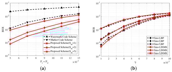
Figure 5.
(a) BER performance of the concatenated watermark code scheme, the concatenated marker code scheme, and the proposed scheme at . (b) BER performance of the watermark code scheme and the proposed scheme at and . denotes the maximal number of synchronizations.
Figure 6a shows the variation in the BER with probabilities , at . Figure 6b shows the the variation in the BER with parameter related to the substitution errors at and . Figure 6 shows a comparison of the performance of the INMS and BP algorithms in the proposed scheme, and the BER performance of the INMS algorithm was approximate to that of the BP algorithm, which verified the effectiveness of the INMS algorithm. In Figure 6b, the BER of the INMS algorithm was higher than that of the BP algorithm when because the INMS algorithm used approximate replacement in the check node update and thus lost some performance. However, the BER of the INMS algorithm was lower than that of the BP algorithm when because the INMS algorithm achieved a better reduction in the correlation effect among the messages after several iterations. A similar case appeared in [19]. The performance of the INMS algorithm was approximate to that of the BP algorithm in all cases. An appropriate correction factor was selected for the INMS algorithm to obtain the above results. Here, , which was obtained with numerous simulations.
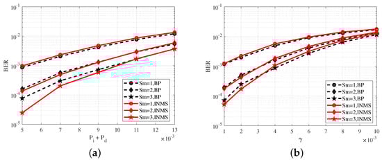
Figure 6.
(a) BER performance of the INMS and BP algorithms at . (b) BER performance of the INMS and BP algorithms at and . The denotes the maximal number of synchronizations.
Combining Figure 5 and Figure 6 obviously shows that BER performance could be significantly improved with several synchronizations. In Figure 5a, for example, at , the BER at the maximal number of synchronizations was reduced by almost 10 times compared to the BER at . At the same time, several synchronizations (i.e., joint decoding) also led to an increase in complexity; thus, we had to consider both performance and complexity in the proposed scheme, and select a suitable .
7. Conclusions
In this paper, we proposed an improved marker code scheme for DNA channels. In this scheme, the marker bits are encoded as the information part of the LDPC code and then mapped into marker bases to correct the synchronization errors. Thus, marker bits not only assist in regaining synchronization, but also play a role in LDPC decoding to improve decoding performance. On the basis of the fact that DNA is a quadratic channel, a novel base-symbol-based synchronization algorithm is proposed. The simulation results demonstrate that the improved scheme achieved substantial performance improvement over the concatenated marker code scheme and concatenated watermark code scheme. Moreover, the INMS algorithm was proposed to reduced decoding complexity in the proposed scheme. The BER performance of this algorithm was approximate to that of the BP algorithm, but its complexity was significantly reduced. The simulation results demonstrated the effectiveness of the INMS algorithm.
Author Contributions
Conceptualization, methodology and original draft preparation, J.T.; supervision, review and editing, G.H.; validation, Y.S. All authors have read and agreed to the published version of the manuscript.
Funding
This research received no external funding.
Institutional Review Board Statement
Not applicable.
Informed Consent Statement
Not applicable.
Data Availability Statement
The datasets used and/or analyzed during the current study are available from the corresponding author on reasonable request.
Conflicts of Interest
The authors declare no conflict of interest.
References
- Siddiqa, A.; Karim, A.; Gani, A. Big data storage technologies: A survey. Front. Inf. Technol. Electron. Eng. 2017, 18, 1040–1070. [Google Scholar] [CrossRef]
- Tazeen, N.; Sandhya, K. A Survey on Some Big Data Applications Tools and Technologies. Int. J. Recent Technol. Eng. 2021, 9, 239–242. [Google Scholar] [CrossRef]
- Clelland, C.; Risca, V.; Bancroft, C. Hiding messages in DNA microdots. Nature 1999, 399, 533–534. [Google Scholar] [CrossRef] [PubMed]
- Taluja, S.; Bhupal, J.; Krishnan, S.R. A Survey Paper on DNA-Based Data Storage. In Proceedings of the 2020 International Conference on Emerging Trends in Information Technology and Engineering (ic-ETITE), Vellore, India, 24–25 February 2020; pp. 1–4. [Google Scholar]
- Bornholt, J.; Lopez, R.; Carmean, D.M.; Ceze, L.; Seelig, G.; Strauss, K. A DNA-based archival storage system. Comput. Archit. News 2016, 44, 637–649. [Google Scholar] [CrossRef]
- Chandak, S.; Tatwawadi, K.; Lau, B.; Mardia, J.; Kubit, M.; Neu, J.; Griffin, P.; Wootters, M.; Weissman, T.; Ji, H. Improved read/write cost tradeoff in DNA-based data storage using LDPC codes. In Proceedings of the 2019 57th Annual Allerton Conference on Communication, Control, and Computing (Allerton), Monticello, IL, USA, 24–27 September 2019; pp. 147–156. [Google Scholar]
- Shomorony, R.H. DNA-Based Storage: Models and Fundamental Limits. IEEE Trans. Inf. Theory 2021, 67, 3675–3689. [Google Scholar] [CrossRef]
- Davey, M.C.; Mackay, D.J.C. Reliable communication over channels with insertions, deletions, and substitutions. IEEE Trans. Inf. Theory 2001, 47, 687–698. [Google Scholar] [CrossRef]
- Ratzer, E.A. Marker codes for channels with insertions and deletions. Ann. Telecommun. 2005, 60, 29–44. [Google Scholar] [CrossRef]
- Weigang, C.; Mingzhe, H.; Jianting, Z.; Qi, G.; Panpan, W.; Xinchen, Z.; Siyu, Z.; Lifu, S.; Yingjin, Y. An artificial chromosome for data storage. Natl. Sci. Rev. 2021, 8, nwab028. [Google Scholar]
- Nakata, R.; Kaneko, H. Synchronization and Asymmetric Error Correction for Nanopore Sequencing. In Proceedings of the IEEE International Conference on Consumer Electronics-Taiwan (ICCE-TW), Penghu, Taiwan, 16–18 June 2021; pp. 1–2. [Google Scholar]
- Gallager, R. Low-density parity-check codes. IRE Trans. Inf. Theory 1962, 8, 21–28. [Google Scholar] [CrossRef]
- Han, G.; Guan, Y.L.; Cai, K.; Chan, K.S.; Kong, L. Embedded Marker Code for Channels Corrupted by Insertions, Deletions, and AWGN. IEEE Trans. Magn. 2013, 49, 2535–2538. [Google Scholar] [CrossRef]
- Ma, S.; Tang, N.; Tian, J. DNA synthesis, assembly and applications in synthetic biology. Curr. Opin. Chem. Biol. 2012, 16, 260–267. [Google Scholar] [CrossRef] [PubMed]
- Ross, M.G.; Russ, C.; Costello, M. Characterizing and measuring bias in sequence data. Genome Biol. 2013, 14, R51. [Google Scholar] [CrossRef] [PubMed]
- Organick, L.; Ang, S.D.; Chen, Y.J.; Lopez, R.; Yekhanin, S.; Makarychev, K.; Strauss, K.; Racz, M.Z.; Seelig, G.; Ceze, L.; et al. Random access in large-scale DNA data storage. Nat. Biotechnol. 2018, 36, 242–248. [Google Scholar] [CrossRef] [PubMed]
- Deng, L.; Wang, Y.; Noor-A-Rahim, M.D.; Guan, Y.L.; Shi, Z.; Gunawan, E.; Poh, C.L. Optimized Code Design for Constrained DNA Data Storage With Asymmetric Errors. IEEE Access 2019, 7, 84107–84121. [Google Scholar] [CrossRef]
- Roberts, M.K.; Sunny, E. Investigations on performance analysis of various soft decision based LDPC decoding algorithms. In Proceedings of the 2017 International Conference on Inventive Computing and Informatics (ICICI), Coimbatore, India, 23–24 November 2017; pp. 175–179. [Google Scholar]
- Jinghu, C.; Dholakia, A.; Eleftheriou, E.; Fossorier, M.P.C.; Hu, X.-Y. Reduced-Complexity Decoding of LDPC Codes. IEEE Trans. Commun. 2005, 53, 1288–1299. [Google Scholar]
Disclaimer/Publisher’s Note: The statements, opinions and data contained in all publications are solely those of the individual author(s) and contributor(s) and not of MDPI and/or the editor(s). MDPI and/or the editor(s) disclaim responsibility for any injury to people or property resulting from any ideas, methods, instructions or products referred to in the content. |
© 2023 by the authors. Licensee MDPI, Basel, Switzerland. This article is an open access article distributed under the terms and conditions of the Creative Commons Attribution (CC BY) license (https://creativecommons.org/licenses/by/4.0/).