Article

Multi-Objective Optimization of LCC-S-Compensated IPT System for Improving Misalignment Tolerance

1
School of Electrical Engineering, Beijing Jiaotong University, Beijing 100044, China
2
School of Intelligent Manufacturing, Nanyang Institute of Technology, Nanyang 473004, China
3
School of Electronic and Electrical Engineering, Cangzhou Jiaotong College, Cangzhou 061100, China
*
Author to whom correspondence should be addressed.
These authors contributed equally to this work.
Appl. Sci. 2023, 13(6), 3666; https://doi.org/10.3390/app13063666
Submission received: 19 January 2023 / Revised: 5 March 2023 / Accepted: 10 March 2023 / Published: 13 March 2023
(This article belongs to the Special Issue Wireless Power Transfer Systems)

Abstract

:
Due to their excellent performance, the inductor–capacitor–capacitor-series (LCC-S)-compensated topologies are extensively used in inductive power transfer (IPT) applications. However, perfect alignment of the system’s contactless couplers is difficult, which leads to serious deterioration of the system output characteristics. In this paper, the influence of the coupler misalignment on the performance of the conventional resonant system is studied. To obtain stable output against varying couplings and loads in a certain range, a novel parameter design method based on the multi-objective particle swarm optimization (MOPSO) algorithm is introduced. The multi-objective optimization framework is developed to analyze the Pareto trade-offs between three conflicting performance metrics, namely output current/voltage ripple, reactive power transmission and component stress. Optimization results depict that misalignment tolerances in both constant current output (CCO)-type and constant voltage output (CVO)-type LCC-S-compensated IPT systems are improved, while a wider load range is suitable for a CCO-type system using the method of compensation parameter optimization. Experimental results are highly consistent with the design, achieving a current fluctuation of no more than 10.5% with a load range from 50 Ω to 100 Ω and a voltage fluctuation of less than 10.4% with a narrow load from 90 Ω to 100 Ω over 100% of coupling variations (from 0.25 to 0.5).

1. Introduction

In recent years, the use of inductive power transfer (IPT) techniques has received much attention and gained popularity. In contrast to the traditional physical contact charging method, the IPT system caters to inherent advantages of safety, convenience, flexibility and strong environmental adaptability. It is widely applied in many applications, such as consumer electronics, implantable medical devices, light rail vehicles, and electric vehicles [1,2,3,4,5]. Most of them are battery-powered devices and demand a load-independent constant current (CC) or constant voltage (CV) charging mode [6,7,8].
IPT systems utilize an alternating magnetic field as a medium to transmit power in the wireless coupler or loosely coupled transformer (LCT). Due to the large leakage inductances, the wireless coupler or LCT absorbs a large value of reactive power, which needs to be compensated for by resonant topologies. Normally, high system efficiency and large power transfer capability can be achieved without any misalignment conditions between the primary and secondary coils. However, misalignment (vertical, horizontal, or angular) between the primary and secondary coupling coils is inevitable [9,10,11], usually resulting in high reactive power, deteriorative outputs and low power transfer efficiency of the system. Therefore, power transfer with a low coupling coefficient has become one of the most challenging issues in an inductive wireless charging system [10,12].
In order to enhance misalignment tolerance, various design and optimization methods have been proposed, including magnetic coupling mechanism designs, control strategies, compensation topology and parameter optimization [13,14]. Among these methods, compensation networks are essential to compensate for the high reactive power of the magnetic couplers. Moreover, the compensated circuits offer interesting features such as soft switching, high efficiency and flexible output voltage/current.
A compensated resonant network typically consists of multiple passive elements, resulting in a variety of circuit characteristics. The tuning of compensation networks plays a vital role in achieving the misalignment tolerance capability, desired stable output features (CC or CV mode) and desired transfer efficiency with a soft-switching operation [15,16]. However, it can be difficult for a compensation circuit to achieve all of the above excellent performance characteristics. Design optimization of compensation parameters using analytical method/equations is difficult due to the complexity of IPT systems, especially with high-order compensation topologies. In addition, the parasitic parameters of different elements cannot be accurately estimated using classical analytical equations. Besides, the conventional methods based on parameter sweeping are time-consuming and require multiple trial and error calculations. Meanwhile, practical constraints and objectives cannot easily be included in the conventional methods [17]. For example, the anti-misalignment performance of basic series–series (SS) topology was improved by improving the conventional parameter selection [18]. However, the results of improvement were insufficient, and the input current was unbounded when the coupling coefficient was very small [19]. Combined with series topology in the primary side and T-type configurable topology in the secondary side, a series hybrid wireless charging system with eight compensation elements and a switch was proposed to obtain CC and CV outputs accompanied by high misalignment [20]. When the secondary side coil moves out of the operating region, the current of the inverter can be limited without an extra controller. Considering the power stationarity and soft-switching implementation, a general design method for the primary compensation network was proposed in [21], in which the transmission power fluctuation was below 20% in the effective coupling coefficient range (0.125, 0.25). In order to extend position tolerance, an LCC-S compensation topology with stable output current was numerically solved in [22]. The series compensation in the secondary side was chosen to fully compensate for the inductance of the secondary coil, and the primary LC compensation parameters were the focus of parameter optimization. In these investigations, parameter selection and optimization were generally obtained through complex derivative calculations, and load variation was usually not considered simultaneously.
Nowadays, artificial intelligence (AI) is rapidly expanding and has been applied to power electronic systems during the past several decades [23]. For practical IPT systems’ feasibility, the misalignment tolerance, along with ideal stable output and low losses, were considered as objective functions in the multi-objective optimization problem. Once the optimization task for a particular application is determined, the optimal solution can be obtained by deterministic programming methods or metaheuristic methods [24]. Deterministic programming methods, which require calculation of the gradient and the Hessian matrix, are challenging for most optimization tasks in the field of power electronics due to their complexity. As a generic end-to-end tool, the metaheuristic method requires less expert experience and is efficient and scalable for a variety of optimization tasks. The metaheuristic methods include trajectory-based methods and population-based methods. Compared to the trajectory-based methods, the population-based methods (genetic algorithm (GA) [25,26], particle swarm optimization (PSO) [27,28], differential evolution [29], ant colony optimization (ACO) algorithm [30], immune algorithm (IA) [31], etc.) are superior in their convergence speed and global searching capability, and they are especially suitable for large-scale optimization issues. For IPT systems’ anti-misalignment optimization, the application of population-based methods to the different types of magnetic couplers are the first to be widely studied by researchers. A nondominated genetic algorithm (NSGA-II) is employed as the optimization solver to find the optimal geometries of bipolar power pads (BPP) coupler in [32]. In [27], a PSO-based optimization design of a W-Type contactless coupler is proposed to improve power transfer stability in the dynamic wireless power transmission system. Compared with the complicated trial-and-error method, the quantity of samples was reduced. As an evolutionary algorithm, PSO algorithm makes the particles in the population continuously move to the optimal position through position updates and avoids complex genetic manipulations. In [33], a holistic comparison of four coupler concepts is discussed using multi-objective Pareto analysis. For compensation parameter optimization, a synchronous optimization of compensation network based on non-dominated sorting genetic algorithm III (NSGA-III) is proposed in [34], which optimizes the demand of constant output voltage but lacks the description of the compromise solution for output fluctuation and system efficiency. A PSO-based parameter design method for a constant-voltage-output-type S-CLC-compensated IPT systems featuring high misalignment tolerance is presented in [35]. However, the primary side adopts series compensation, which will be affected by unbounded current when there is almost no coupling between the primary and secondary sides. Due to the high information processing and evolution capabilities, the IA algorithm is widely applied in pattern recognition and classification problems [31]. However, the robustness of the algorithm is heavily affected by the antibody levels. As for the ACO algorithm, the convergence speed and the quality of the solutions are very sensitive to the initial parameters [30]. Thanks to the advantages of easy implementation, high accuracy, and fast convergence speed, the PSO algorithm is widely applied and is selected to be executed to extract the optimal parameters in this paper.
In the design process, the number of compensating elements determines the design flexibility of the system, and multiple compensating elements will make the system have higher design freedom. As typical higher-order topologies, the resonant LCC-based topologies are extensively used in the primary side of the IPT systems to supply the transmitting coil with a constant current which induces a constant voltage on the secondary side coil. Meanwhile, LCC-based compensation provides a higher degree of design freedom. However, too many compensation components would increase the cost and produce more losses. Using a single resonant element in the secondary series compensation, an LCC-S compensation network can be composed. At the resonant frequency, the resonant elements in the LCC-S topology can both be tuned to achieve constant current output [22] or constant voltage output [36]. In order to prevent excessive compensation components from deteriorating system efficiency and to provide more design freedom to implement the desired characteristics, an LCC-S compensation network is adopted in this paper.
The inevitable coil misalignment is the most destabilizing factor affecting the system’s performance. The purpose of this paper is to realize the stable charging outputs by the achievement of CC output or CV output. With the aid of an artificial intelligence optimization algorithm, this paper attempts to obtain well-designed compensation parameters for an LCC-S-compensated IPT system, in which the current or voltage output are insensitive to the coupling coefficient and load variation, simultaneously. Based on different modes of a loosely coupled transformer, Section 2 provides the overview of two conventional types of LCC-S compensation topologies, where the parameter resonant tuning design principles and output characteristics are presented. The detailed optimization process of multi-objective PSO is described in Section 3. The experimental verification is presented in Section 4. Finally, conclusions are outlined in Section 5.

2. Design and Analysis of LCC-S Compensation Topologies

In the magnetic coupler, a large amount of magnetic flux leakage remains; thus, in order to improve the transfer power and system efficiency, compensated resonant circuits are introduced. The mutual inductance model (M-model) and transformer model (T-model) are usually used to describe the system used to compensate for the mutual inductance or leakage inductance of a loosely coupled transformer. The application of the M-model aims to simplify the circuit and reduce the number of variables by removing the leakage inductance and the ratio from the model. As shown in Figure 1a, in the M-model, LP and LS are self-inductances of the primary and secondary coils. UP and IP are the input voltage and current at the primary side of the loosely coupled transformer, and US and IS are the output voltage and current at the secondary side. M stands for the mutual inductance between the transmitting and receiving coils. The induced voltage is generated in the primary and secondary side coils, which are denoted as −jωMIS and jωMIP. The ω parameter is the circuit operating frequency, which equals the switching frequency of the inverter voltage. In the T-type model of LCT, the magnetic couplers are replaced, and all the parameters are reflected to the primary-side. As shown in Figure 1b, LP′, LS′ and LM are the reflected leakage inductances of the primary coil, secondary coil and mutual inductance, respectively. Although the two models have different forms, they can be converted to each other according to the two-port network equivalence.
The circuit of the LCC-S-compensated IPT system is shown in Figure 2, which includes three parts: the voltage power supply Ud, the resonant tank and the couplers and load RO. LP1, CP1, CP2 and CS make up the LCC-S compensation topology. The MOSFETs S1S4 combine into the full bridge inverter, and D1D4 represent the rectifier diodes. Cf is the filter capacitor. Here, UAB, IAB, Uab and Iab are the root mean square (RMS) values of the fundamental harmonics of uAB, iAB, uab and iab, respectively. When the phase-shifting angle is zero, the value of UAB can be calculated using (1) according to the first harmonic approximation (FHA). Similarly, the equivalent AC load resistance RE can be expressed as (2).
U AB = 2 2 π U d
R E = 8 π 2 R O
In the LCC-S topology, a simple series capacitor forms the receiving side compensation networks and the secondary impedance Zsec is expressed as
Z sec = R E + 1 j ω C S + j ω L S
The inverter input impedance Zin of the compensate circuit and load is given as
Z in = ( ( ω M ) 2 Z sec + 1 j ω C P 2 ) 1 j ω C P 1 + j ω L P 1
Based on the defined impedances of the circuit, the input current of the inverter IAB and the currents flowing into two coupling coils are derived as
{ I AB = U AB Z in I LP = I AB ( Z in j ω L P 1 ) / ( ( ω M ) 2 Z sec + 1 j ω C P 2 ) I LS = I LP j ω M Z sec
Therefore, the output current IRO and the output voltage URO can be expressed as
{ I RO = 2 2 π I LS = 2 2 π j ω M Z sec I LP U RO = 2 π 4 U ab = 2 2 π j ω M Z sec I LP R O
Different power transmission characteristics can be obtained using heterogeneous parameter compensation. Firstly, the M-type model is used to procure a load-independent voltage output in the compensation design for the LCC-S topology. A resonant capacitor connects in series to the receiving coil, which compensates for the self-inductance of the receiving coil. The primary LCC compensation circuits are typically designed to have zero phase angle (ZPA) input impedance or weak inductive input impedance for zero-voltage switching (ZVS) turn-on operation of MOSFETs. The primary LCC resonant topologies can supply the transmitting coil with a constant current, and a constant voltage on the secondary side coil is induced. After series resonance consisting of a secondary coil and compensation capacitor, the load can obtain excellent constant current output characteristics. The compensation design is as follows:
{ C P 1 = 1 / ( ω 2 L P 1 ) C P 2 = 1 / [ ω 2 ( L P L P 1 ) ] C S = 1 / ( ω 2 L S )
For the CVO type LCC-S compensation, the output voltage can be expressed as
U RO = M L P 1 U d
In order to obtain good performance of load-independent current output, the T-type model of LCT was used to design the LCC-S compensation topology parameters. Part of the primary-side compensation capacitor CP1 is used to compensate for the inductance LP1, and the other part is tuned to compensate for the reflected mutual inductance LM. The specific compensation elements can be calculated from [16]. The values of CP1, CP2 and CS are designed by the following equations to achieve resonant at the switching frequency:
{ C P 1 = 1 ω 2 L P 1 + 1 ω 2 n M C P 2 = 1 ω 2 ( 1 k ) L P C S = 1 ω 2 ( 1 k ) L S
where k is the coupling coefficient related to the mutual coupling of the couplers, defined as: k = M / L P L S , and n denotes the turn ratio of the loosely coupled transformer.
Therefore, the constant output current IRO through RO can be calculated as
I RO = 8 π 2 n U d ω L P 1
Equations (8) and (10) imply that the IPT system has constant voltage/current output characteristics and that the system can achieve different voltage/current output levels by using LP1 according to requirements.
However, the above compensation parameters are designed without considering coil misalignment. When the spatial position of the two coupling coils changes, the transmission power of the system will fluctuate drastically. The output voltage sensitivity with respect to the mutual inductance is derived as
U RO M = 8 π 2 j R O ω U d Z in Z sec ( 1 M Z in ( 2 M ω 2 + j ( ω M ) 2 Z sec j ω M ) )
From (11), the input impedance Zin is also related to the mutual inductance coupling, resulting in analytical solutions becoming difficult to obtain. In this paper, the nominal output levels were chosen to be 100 V and 1 A. The minimum coupling coefficient was set to 0.25, and within almost 100% variation, the coupling coefficient was 0.5 with no misalignment. Due to their simplicity in terms of structure and component count, the planar circular coils were adopted in the analysis. The load ranges from 50 Ω to 100 Ω were investigated. Table 1 summarizes and lists the system specifications. The two LCC-S resonant topologies were designed with identical voltage/current levels. The power transfer capacities with varying coupling coefficients and loads are shown in Figure 3.
As can be observed from Figure 3a, the output voltage of LCC circuit was proportional to the coupling coefficient. For the results of CCO-type topology in Figure 3b, the power transfer showed a rapid ascent in misalignment condition. The currents flowing through the power supply would be large enough to damage the inverter if drastic misalignment occurs. In order to indicate the misalignment tolerant capability of the system, the output voltage fluctuation range hUR is defined by (12), where URO_max and URO_min are the maximum and minimum output voltages of the LCC-S-compensated IPT system within the whole coupling coefficient and load range. Similarly, the output current fluctuation range hIR is defined by (13), where IRO_max and IRO_min are the maximum and minimum output currents. From Figure 3, voltage and current fluctuations of 33.3% appear with a coupling range from over 0.5 to 0.25. The two LCC-S resonance compensations make the system severely sensitive to coupling variations. Therefore, improving the IPT system performance, including both the coupling and load change throughout the operation, is important.
h UR = ( U RO_max U RO_min ) / ( U RO_max + U RO_min ) × 100 %
h IR = ( I RO_max I RO_min ) / ( I RO_max + I RO_min ) × 100 %

3. Multi-Objective Optimization of Compensation Parameters

As previously mentioned, the design optimization problems of the IPT system often require the optimization of conflicting objectives. A widely used method in the optimization of multi-objective problems is the Pareto optimality algorithm [37]. The Pareto optimal algorithm maximizes one of the objectives while maintaining other conflicting objectives at their maximum possible. The output of a Pareto optimization algorithm includes a solution vector and its corresponding objective function, called the Pareto front. In order to broaden the charging region and reduce the output fluctuations, a multi-objective optimization framework based on the PSO algorithm was utilized to search for the optimal solutions from the Pareto front. The PSO method was first put forward by James Kennedy and Russell Eberhart in 1995 [38]. For the PSO algorithm, at each iterative exploration, the candidate solutions are diversified or incorporated and replaced with new candidate solutions to improve the quality of the current generation of population. As a result, the suitability of the population is improved by iteration. The targets of the system performance and the practical constraints were considered as follows.

3.1. Overview of MOPSO Algorithm

With faster computing speed and better global search ability, the PSO algorithm can converge to the optimal solution with high probability, which is suitable for dynamic optimization. In order to solve the multi-objective model, the multi-objective particle swarm optimization (MOPSO) algorithm was used in this paper.
The algorithm first generates the initial solution; that is, the population X = {X1, X2, X3, ⋯, Xm} composed of m particles is randomly initialized in the feasible solution space, where the position Xi = {xi1, xi2, xi3, …, xiD} of each particle represents a solution. The velocity of the ith particle is also a D-dimensional vector, denoted as Vi = {vi1, vi2, vi3, …, viD}. The optimal position searched for the moment by the ith particle is called the individual extreme and is denoted as pi-best, while the optimal position searched by the whole particle swarm is the global extreme, which is denoted as gbest. Each possible solution is expressed as a particle in the population, and each particle has its own velocity vector, position vector and a fitness determined by the objective function. In each iteration, the particle will update itself by tracking with two extreme values. The individual optimal vector pi and the global optimal vector pg at the current moment are determined by calculating the objective function. During each iteration, each particle updates its speed and position according to:
v i k + 1 = w v i k + c 1 r 1 ( p i k x i k ) + c 2 r 2 ( p g k x i k )
x i k + 1 = x i k + v i k + 1
where w is the weight of inertance, c1 and c2 are learning factors and r1 and r2 are independent random numbers, which are evenly distributed on [0, 1]. The value of the inertia weight w indicates the ability to inherit the current velocity of the particle. In order to enhance the local optimization ability, this paper adopts a small, fixed weight. The acceleration constants c1 and c2 regulate the maximum stride length in the direction of pi-best and gbest, respectively. They determine the influence of individual and group experience of particles on the trajectory of particles and reflect the information exchange within the particle swarm. c1 = c2 is usually set so that individual experience and group experience have the same important influence and the final optimal solution is more accurate. In general, c1 and c2 can take values around 2. From the update formula of particles, the moving speed of a particle is determined by three parts: its original speed, the distance from its best experience and the distance from the group’s best experience. Their relative importance is determined by the weight coefficient w, c1 and c2, respectively.

3.2. Optimization Objectives

To achieve optimized parameters for the IPT system, the objectives of the optimization must be provided, which are defined as follows:
(1)
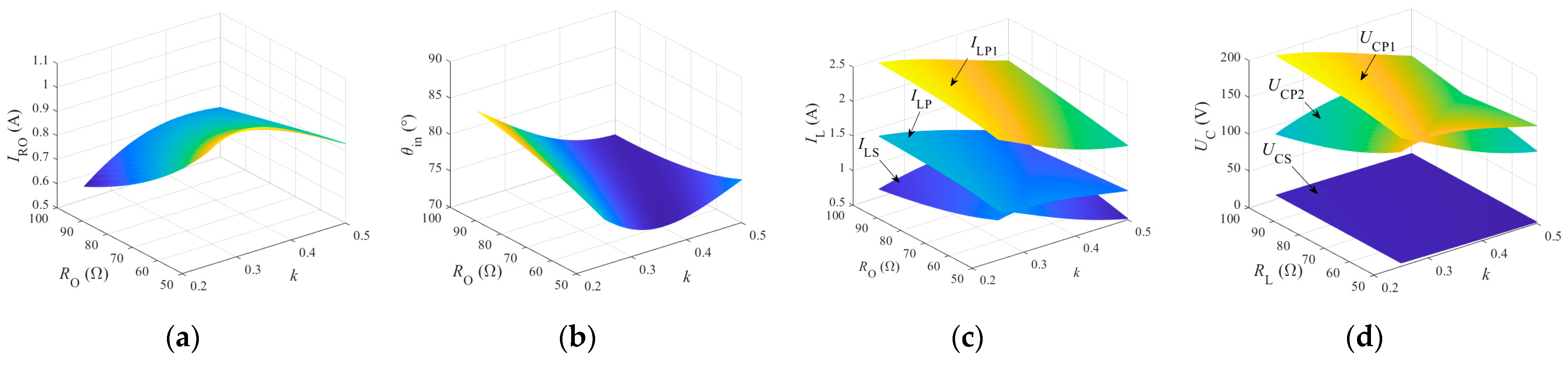
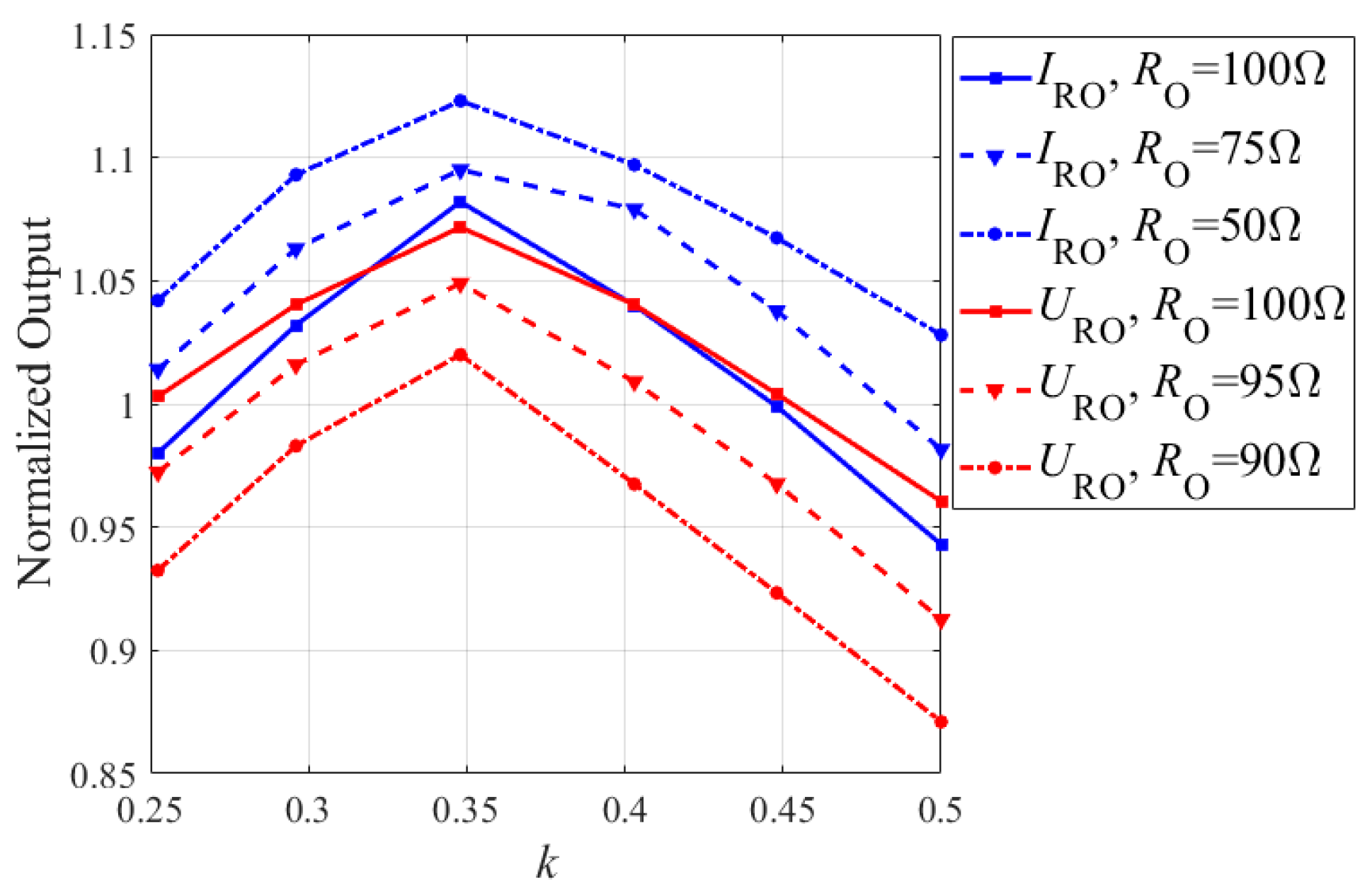
Minimize output fluctuations: In any state where k ϵ (kmin, kmax) and RO ϵ (ROmin, ROmax), the current IRO [k(i), RO(j)] across the load is most approximate to the design value IRO_D for the CC mode, and the voltage URO [k(i), RO(j)] over the load should be close to the design value URO_D for the CV mode. k(i) and RO(j) represent the ith k and jth RO, respectively. Here, the square of the current difference is used to represent output fluctuations, and its mathematical description is defined as
f RO = { { I RO [ k ( i ) , R O ( j ) ] I RO_D } 2 for   CC   mode { U RO [ k ( i ) , R O ( j ) ] U RO_D } 2 for   CV   mode
(2)
Reduce current stresses across inductor and coils: The voltage stresses over capacitors and current stresses through inductors result in high power loss due to ESRs in the passive compensation components. In particular, the larger ESRs in the inductor and coils have a great impact on system efficiency. Therefore, the secondary objective is to minimize the current stress across the inductor and coils. The sum of current stresses through the inductor and coils are involved in the optimization function as follows:
f IL = I LP 1 [ k ( i ) , R O ( j ) ] + I LP [ k ( i ) , R O ( j ) ] + I LS [ k ( i ) , R O ( j ) ]
(3)
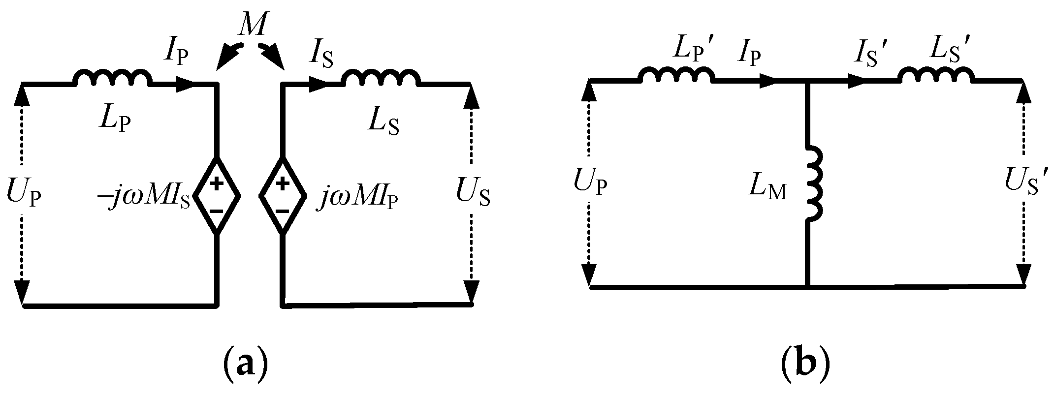
Lessen magnetizing power in LCT: For the loosely coupled coils, neglecting the magnetic losses and coil resistance, the active power transfer from the transmitter to the receiver can be given as
P T = ω M I LP I LS sin θ PS
where ILP and ILS are the RMS value of the primary and secondary coil currents, respectively, and θPS is the phase difference of the fundamental current phasors between the transmitting and receiving winding. The reactive power flowing between couple coils can be given as
Q T = ω ( L P I LP 2 + L S I LS 2 + 2 M I LP I LS cos θ PS )
For a traditional compensated LCT, when the induced current IS lags IP by a quarter cycle, the maximum power can be transferred from LP to LS. However, after anti-misalignment optimization, the detuned compensation parameters make θPS no longer equal to π/2. The reactive power causes coil magnetization, bringing more copper and core losses. In order to improve the efficiency of LCT, the ratio between the reactive power and active power should be kept to a minimum. The ratio, taken as the third objective function, is given as
f θ LS = | Q T | | P T | = | L P I LP 2 + L S I LS 2 + 2 M I LP I LS cos θ PS M I LP I LS sin θ PS |
The targets of the optimization consist of three parts. The most important part is to minimize the output current and voltage fluctuation for different coupling coefficients and loads. The other two parts are designed to improve transmission efficiency. Taken together, the objective function is
F = min i = 1 N K j = 1 N RO ( f RO , f IL , f θ LS )
where Nk and NRO are set as the sampling number of coupling coefficients and loads.

3.3. Setting Constraints

In order to reduce switching losses and improve IPT system efficiency, the system should work in soft-switching conditions; that is, the input impedance of the IPT system should be inductive. The input impedance angle θin needs to be greater than 0. When the input impedance angle is less than 0, a large penalty coefficient Mpe is added to the objective function.
Considering the physical boundaries and cost of passive electrical components, the compensation capacitors and compensation inductors are limited as follows:
{ L min L i L max C min C j C max
Meanwhile, voltage limits for capacitors and current limits of inductors for compensation networks should also be given to protect circuit safety, which are limited as follows:
{ U C U C max I L I L max

3.4. Implementation of MOPSO

Four compensation parameters, LP1, CP1, CP2 and CS1, need to be optimized for the LCC-S compensation IPT system. Therefore, this is a four-dimensional optimization problem for the PSO algorithm. The velocity of each particle is constrained within the range [Vmin, Vmax], and the values of the four different velocities are derived by the positive integers Ni. The position is limited within the range [Xmin, Xmax], which is determined by the component constraints. In order to describe the optimization process clearly, the flowchart of the MOPSO algorithm is shown in Figure 4. As shown in Figure 4, the MOPSO algorithm is divided into about seven steps: (1) initialization of parameters; (2) velocities and positions update; (3) calculation of fitness; (4) update of individual optimal position pi-best (k); (5) update of archives; (6) update of global optimal vector gbest (k); (7) repeat steps (2) through (6) until the end of the loop condition is met.
The desired output current IRO_D was set to 1 A and the desired output voltage URO_D was set to 100 V. The basic setting of the MOPSO optimization process is listed in Table 2. The number of particles is Np = 200, and the dimension of each particle is four, which corresponds to LP1, CP1, CP2 and CS. The range of compensated inductance is 10–1000 μH and the range of each compensated inductance capacitance is 0.1–800 nF. The repository size for each iteration is 200 to show more optimization results. The maximum number of iterations is limited to 200, so as not to prolong the simulation time. The maximum and minimum moving velocities of particles is limited by 1/200 of the range of each particle. In addition, the inertia factor w and learning factors c1, c2 take the empirical value, which are 0.7, 1.8, 1.8, respectively. In order to solve the nonlinear optimization problem proposed in this case, the MOPSO program was written in the MATLAB software. The time cost is about 74.9 s and is realized by a computer (Intel Core i7-9700: 3.00 GHz, RAM: 32 GB).
For the CCO-type system, all the solutions successively generated in the archive after 200 iterations are shown in Figure 5a (3D diagram). In each iteration, the MOPSO algorithm performed non-dominated sorting and finally converged to the Pareto front. The optimization Pareto front of the output current fluctuation versus input impedance angle and current stresses of three inductors was obtained as shown in Figure 5b (2D diagram). According to the Pareto front, it is evident that different weight combinations of three objectives can lead to large variant results. In Figure 5, fIRO represents the output current fluctuation function, which is the most important target. fIL represents the second objective function, which is the sum of current stresses with respect to load and coupling coefficient. The color bar in the figure represents the sum of the ratio between the reactive power and active power in the LCT, which is the third objective function fθPS. From Figure 5, the output current ripple of solution A is the minimum, but the current stresses and reactive power is large. Solution B has the smaller current stresses and reactive power, but the greater fluctuation of output current. For the solutions with fIRO greater than B, the output fluctuation of the system would worsen, which deviates from the anti-misalignment characteristic pursued and will not be considered. The Pareto front enables decision makers to select the best compromise or near-best solution that reflects trade-offs among key objectives. Therefore, reasonable compensation parameters can be selected based on the compromise method to meet different design requirements for the IPT system.
Specific to the CCO-type compensation network, after optimization, solution point A, which had the lowest fitness function value for the output current fluctuation, and point B, which had trade-offs of the three optimization objectives, were selected for comparison. The obtained four compensation parameters corresponding to point A were LP1 = 147.6 μH, CP1 = 41.87 nF, CP2 = 214.88 nFand CS = 8.77 nF, while for point B, they were LP1 = 217.43 μH, CP1 = 36.61 nF, CP2 = 47.36 nF and CS = 13.02 nF. With the optimized four parameters, the load current versus coupling coefficient and load can be obtained, as shown in Figure 6a and Figure 7a. With the parameters at point A, the minimum load current, 0.87 A, was achieved when k and RO were 0.25 and 100 Ω, respectively. The maximum load current was 1.08 A when k and RO were 0.36 and 50 Ω. Therefore, the output current fluctuation range of the compensation topology was less than 10.8%. Similarly, with the parameters at point B, the output current fluctuation of 29.67% was obtained. Simultaneously, the inverter no longer has a tremendous current when two coils seriously misalign, which protects the power supply.
From Figure 6 and Figure 7, it can be seen that the input impedance angles of the two IPT systems remained at a positive value, which ensured the ZVS operation of the inverter switches. However, it can be observed that, generally, the phase angle of Case A was greater than that of Case B as they tried to reduce the output fluctuations. In Case A, the vital objective function is minimizing the current variation and a balanced trade-off of the three optimization objectives is better reflected in Case B. Furthermore, it can be seen from Figure 6 that although group A parameters could obtain the characteristics of remarkable stable current output, the maximum current on the compensation inductor LP1 and the maximum voltage over CP1 reached 6.37 A and 412.89 V when k = 0.25 and RO = 100 Ω. Coils and switches with high current tolerance are needed. This can be explained by the large amount of reactive power introduced into the IPT system. For Case B, although the current stresses on LP1 and the voltage stresses over compensation capacitors were relatively small, a nearly 30% fluctuation in the output current appeared.
For the new CVO-type compensation network, the output voltage results derived by the proposed method were seriously affected by the load range. Taking 100 Ω as the maximum load, for the minimum range of 50, 70 and 90 Ω load, respectively, the best solutions among multiple optimized solutions were ultimately selected. Under different load ranges, the comparison diagram of multi-objective Pareto solutions for the system is shown in Figure 8, where fURO represents the first objective function; namely, output current fluctuation. It can be observed that the Pareto front changes in a consistent trend, but different fitness function values are obtained, that is to say, the objective function is sensitive to the range of load, and the influence on misalignment tolerance capability can be significantly reduced by a narrow load range. In order to obtain the appropriate anti-misalignment effect, the optimization results of loads ranging from 90 to 100 Ω were studied. From Figure 8, the voltage ripple and inductance current stresses cannot be optimized at the same time, and they are negatively correlated, while the ratio between the reactive power and active power has no positive or negative correlation with the two objects. Hence, it is more reasonable to take it as an important reference factor in the whole multi-objective optimization process. This paper takes minimum voltage ripple as the highest priority, considering both the reactive power and electrical element stress. Therefore, the reasonable solution point C that reflects trade-offs among the key objectives were selected from the Pareto front. The four compensation parameters obtained corresponding to point C were LP1 = 206.51 μH, CP1 = 33.64 nF, CP2 = 692.13 nF and CS = 11.82 nF. The output voltage, input impedance angle, current stresses on inductors and voltage stresses over capacitors varying with the coupling coefficient and load are shown in Figure 9. As with the CCO type, the voltage defining fluctuation with the Case C compensations were indicated to be able to be maintained under 10.45% when the coupling coefficient varied from 0.5 to 0.25. The maximum current and voltage stress were 4.18 A and 375.26 V, respectively, which were both within the acceptable range for the compensation components. The impedance is inductive within the full coupling range, which can fulfill the ZVS requirement for the system. From Figure 9c, it can be seen that the transmitting coil current of the proposed scheme was negatively correlated with the coupling coefficient, indicating that the current of the transmitting coil tracked and compensated the coupling coefficient’s influence on the output voltage.
Based on the above analysis, the LCC-S-based IPT systems can enhance different misalignment-tolerant capabilities with compensating parameter optimization, which is realized at the cost of introducing extra reactive power. Moreover, it can also be observed in Figure 6, Figure 7 and Figure 9 that the optimized curve was approximately a parabola with different gradients and a coupling turning point, and the key features of the output profile are parametrically dependent. Meanwhile, the value of parameters affecting the efficiency and cost also needs to be considered. Possessing the smallest volatility of only around 10%, Case A and Case C had the best power transfer stability. Nevertheless, the introduction of more electric stresses on passive elements resulted in lower system efficiency. Notwithstanding, the robustness of power transfer and the high degree of design freedom are favorable in low-power applications. With small device stresses, Case B could provide a 30% current output fluctuation, which is more suitable for electrical devices with high requirements of both power and efficiency, such as stationary electric vehicle wireless charging. Case C illustrates that, after parameter optimization, the CVO-type IPT system could not meet the stable output demand in the scenario of large offset and wide load simultaneously. Therefore, if the load changes over a wide range, extra impedance matching circuits may need to be added between the rectifier and the actual load.

4. Experimental Verification

A 100 W prototype was built to verify the misalignment-tolerance capability of the proposed optimized compensation topologies. The photograph of the realized prototype is shown in Figure 10. The designed and measured circuit parameters are tabulated in Table 3. The primary inverter consists of four MOSFET IPW90R120C3, and four DSE12 × 101-06 A units were used for the secondary rectifier. The planar circular coils without ferrites were used to achieve contactless energy transmission and their inductances LP and LS were 268.6 and 269.2 μH, respectively. The gap distance of two coils was 42 mm. The coupling coefficient dropped from 0.5 to 0.25 by moving the secondary coil different distances on the radial direction from 0 to 125 mm.
Implemented with Case A in the LCC-S compensation topology, the normalized output currents versus coupling coefficient are shown in Figure 11. The output current fluctuations of all three different load prototypes were quite small. Around a specific turning point at which the output trend reversed, the gradient of current gain variation was damped, thus significantly reducing the sensitivity of the output characteristic to coupling fluctuation. The outlines of these three curves are very similar to those in Figure 6a. The maximum output current was 1.12 A when the coupling coefficient was approximately 0.35 with the minimum load. The minimum output current was 0.94 A with the maximum load and coupling coefficient. When the value of R decreased, the fluctuation of the output current was smaller. With Case A parameters, the output current fluctuation was insensitive to both coupling coefficient and load, and the fluctuation was only 8.82% in the whole operating range. Some minor discrepancy can be mainly attributed to slight differences between the real parameters and designed ones.
With Case C, the relationship between the normalized output voltage of the LCC-S compensation topology and the coupling coefficient is also depicted in Figure 11. The output voltage first rose and then decreased with respect to misalignment, which conformed to the theoretical analysis, indicating a strong misalignment tolerant capability, especially with the light load. Contrary to the CCO type, the output voltage did not increase as the resistance reduced. Due to the inevitable nonideal factors, such as equivalent resistance in power devices and voltage drop of diodes, the measured power transfer was lower than the designed value. However, the maximum voltage fluctuation with the proposed compensation network was less than 10.4% over the coupling range from 0.25 to 0.5.
Figure 12 and Figure 13 show the steady-state waveforms of two types of compensation topologies designed by the proposed method under maximum and minimum misalignment, respectively. The output current iRO and voltage uRO was almost constant for different coupling and varying load conditions. For the CCO- and CVO-type compensation topologies, the input current iAB lagged behind the voltage uAB, and Zin was always inductive. The fluctuation of output voltage was significantly reduced compared to conventional methods, demonstrating that misalignment tolerance through automatic adjustment of reactive power was realized.
The DC–DC measurement efficiencies of these two topologies versus the coupling coefficient at 100 Ω are shown in Figure 14. The system efficiencies of both topologies increased with increasing coupling. For the CVO type, the maximum efficiency of the new design reached 91.2% at k = 0.45 while delivering 100 W power. The highest efficiency of the CCO-type system reached 73.84%, which is acceptable considering the power level. With a lower coupling coefficient, the efficiency of both the CCO- and CVO-type IPT systems will decrease. The main losses of the LCC-S compensation system are: MOSFET loss, two coupling coils’ loss of LCT, compensation inductor and capacitor loss, diode loss, filter capacitor loss and others. It can be seen from the highest efficiency of the CCO-type system that the power consumed by MOSFETs accounted for the largest proportion (42%) of the switching loss.

5. Conclusions

In this paper, a MOPSO-based compensation parameter optimization design scheme for CCO- and CVO-type LCC-S-compensated IPT systems is proposed to improve misalignment tolerance. The multi-objective functions (including output fluctuation, current stresses and reactive power requirement) and physical constraints (including size of components, voltage and current withstanding capability) are identified in detail. Based on the Pareto front of the optimization results, the proposed methods enhance the robustness of the power transfer response to both coupling variations and loads. Moreover, the ZVS operation can be realized for the primary power switches under full coupling range operations. The misalignment region of the wireless coupler exceeds the vertical distance of two coils by about 125 mm. When implementing the optimized parameters, the CCO-type LCC-S-compensated system was demonstrated to be able to keep the current fluctuation under 8.8%, within 100% variation in both coupling and load. The experimental results show that the voltage fluctuation was not more than 10.4% with a coupling range of 0.25–0.5 and a narrow load range. The CVO-type IPT system cannot meet the stable output demand in the scenario of large misalignment and wide load simultaneously. Therefore, if the load changes over a wide range, extra impedance matching circuits may need to be added between the rectifier and the actual load. The compensation optimization method in this paper can be integrated with the outstanding magnetic couplers and excellent control strategies to further improve the anti-misalignment performance and extend dynamic wireless charging.

Author Contributions

Conceptualization, Q.T.; methodology, R.L. and X.Y.; software, J.Y. and R.L.; validation, R.L. and J.Y.; investigation, Q.L.; writing—original draft preparation, J.Y., A.Y. and R.L.; writing—review and editing, Q.T.; funding acquisition, A.Y. All authors have read and agreed to the published version of the manuscript.

Funding

This research was funded by The Cangzhou Plan Guide Project for Key Research, grant number 204103003.

Institutional Review Board Statement

Not applicable.

Informed Consent Statement

Informed consent was obtained from all subjects involved in the study.

Conflicts of Interest

The authors declare no conflict of interest.

References

  1. Nithiyanandam, V.; Sampath, V. Approach-Based Analysis on Wireless Power Transmission for Bio-Implantable Devices. Appl. Sci. 2023, 13, 415. [Google Scholar] [CrossRef]
  2. Nutwong, S.; Sangswang, A.; Naetiladdanon, S. An Inverter Topology for Wireless Power Transfer System with Multiple Transmitter Coils. Appl. Sci. 2019, 9, 1551. [Google Scholar] [CrossRef] [Green Version]
  3. Yang, X.; Yang, J.; Fan, J.; Wang, B.; Li, D. A Magnetic Field Containment Method for an IPT System with Multiple Transmitting Coils Based on Reflective Properties. Electronics 2023, 12, 653. [Google Scholar] [CrossRef]
  4. Mai, R.; Chen, Y.; Zhang, Y.; Yang, N.; Cao, G.; He, Z. Optimization of the passive components for an S-LCC topology-based WPT system for charging massive electric bicycles. IEEE Trans. Ind. Electron. 2018, 65, 7. [Google Scholar] [CrossRef]
  5. Feng, H.; Tavakoli, R.; Onar, O.C.; Pantic, Z. Advances in High-Power Wireless Charging Systems: Overview and Design Considerations. IEEE Trans. Transp. Electrif. 2020, 6, 886–919. [Google Scholar] [CrossRef]
  6. Jo, S.; Shin, C.-S.; Kim, D.-H. Novel Design Method in Wireless Charger for SS Topology with Current/Voltage Self-Limitation Function. Appl. Sci. 2023, 13, 1488. [Google Scholar] [CrossRef]
  7. Li, J.; Zhang, X.; Tong, X. Research and Design of Misalignment-Tolerant LCC–LCC Compensated IPT System with Constant-Current and Constant-Voltage Output. IEEE Trans. Power Electron. 2023, 38, 1301–1313. [Google Scholar] [CrossRef]
  8. Li, G.; Jo, C.-H.; Shin, C.-S.; Jo, S.; Kim, D.-H. A Load-Independent Current/Voltage IPT Charger with Secondary Side-Controlled Hybrid-Compensated Topology for Electric Vehicles. Appl. Sci. 2022, 12, 10899. [Google Scholar] [CrossRef]
  9. Campi, T.; Cruciani, S.; Maradei, F.; Feliziani, M. Efficient Wireless Drone Charging Pad for Any Landing Position and Orientation. Energies 2021, 14, 8188. [Google Scholar] [CrossRef]
  10. ElGhanam, E.; Hassan, M.; Osman, A.; Kabalan, H. Design and Performance Analysis of Misalignment Tolerant Charging Coils for Wireless Electric Vehicle Charging Systems. World Electr. Veh. J. 2021, 12, 89. [Google Scholar] [CrossRef]
  11. Varikkottil, S.; Febin Daya, J.L. Estimation of Optimal Operating Frequency for Wireless EV Charging System under Misalignment. Electronics 2019, 8, 342. [Google Scholar] [CrossRef] [Green Version]
  12. Ghazizadeh, S.; Ahmed, K.; Seyedmahmoudian, M.; Mekhilef, S.; Chandran, J.; Stojcevski, A. Critical Analysis of Simulation of Misalignment in Wireless Charging of Electric Vehicles Batteries. Batteries 2023, 9, 106. [Google Scholar] [CrossRef]
  13. Niu, S.; Zhao, Q.; Chen, H.; Yu, H.; Niu, S.; Jian, L. Underwater Wireless Charging System of Unmanned Surface Vehicles with High Power, Large Misalignment Tolerance and Light Weight: Analysis, Design and Optimization. Energies 2022, 15, 9529. [Google Scholar] [CrossRef]
  14. Vu, V.B.; Ramezani, A.; Triviño, A.; González-González, J.M.; Kadandani, N.B.; Dahidah, M.; Pickert, V.; Narimani, M.; Aguado, J. Operation of Inductive Charging Systems Under Misalignment Conditions: A Review for Electric Vehicles. IEEE Trans. Transp. Electrif. 2023, 9, 1857–1887. [Google Scholar] [CrossRef]
  15. Qu, X.; Chu, H.; Huang, Z.; Wong, S.C.; Chi, K.T.; Mi, C.C.; Chen, X. Wide Design Range of Constant Output Current Using Double-Sided LC Compensation Circuits for Inductive-Power-Transfer Applications. IEEE Trans. Power Electron. 2019, 34, 2364–2374. [Google Scholar] [CrossRef]
  16. Qu, X.; Jing, Y.; Han, H.; Wong, S.-C.; Tse, C.K. Higher Order Compensation for Inductive-Power-Transfer Converters with Constant-Voltage or Constant-Current Output Combating Transformer Parameter Constraints. IEEE Trans. Power Electron. 2017, 32, 394–405. [Google Scholar] [CrossRef]
  17. Pearce, M.G.S.; Covic, G.A.; Boys, J.T. Robust ferrite-less double d topology for roadway IPT applications. IEEE Trans. Power Electron. 2019, 34, 6062–6075. [Google Scholar] [CrossRef]
  18. Feng, H.; Cai, T.; Duan, S.; Zhang, X.; Hu, H.; Niu, J. A Dual-Side-Detuned Series–Series Compensated Resonant Converter for Wide Charging Region in a Wireless Power Transfer System. IEEE Trans. Ind. Electron. 2017, 65, 2177–2188. [Google Scholar] [CrossRef]
  19. Patil, D.; McDonough, M.K.; Miller, J.M.; Fahimi, B.; Balsara, P.T. Wireless Power Transfer for Vehicular Applications: Overview and Challenges. IEEE Trans. Transp. Electrif. 2018, 4, 3–37. [Google Scholar] [CrossRef]
  20. Gong, Z.-W.; Li, J.-G.; Tong, X.-Q. Misalignment-Tolerant Series Hybrid with Active Adjustable Constant Current and Constant Voltage Output Wireless Charging System. Energies. 2021, 14, 7594. [Google Scholar] [CrossRef]
  21. Zhao, J.; Cai, T.; Duan, S.; Feng, H.; Chen, C.; Zhang, X. A General Design Method of Primary Compensation Network for Dynamic WPT System Maintaining Stable Transmission Power. IEEE Trans. Power Electron. 2017, 31, 8343–8358. [Google Scholar] [CrossRef]
  22. Yang, J.; Zhang, X.; Zhang, K.; Cui, X.; Jiao, C.; Yang, X. Design of LCC-S Compensation Topology and Optimization of Misalignment Tolerance for Inductive Power Transfer. IEEE Access 2020, 8, 191309–191318. [Google Scholar] [CrossRef]
  23. Zhao, S.; Blaabjerg, F.; Wang, H. An Overview of Artificial Intelligence Applications for Power Electronics. IEEE Trans. Power Electron. 2021, 36, 4633–4658. [Google Scholar] [CrossRef]
  24. De Leon-Aldaco, S.E.; Calleja, H.; Alquicira, J.A. Metaheuristic optimization methods applied to power converters: A review. IEEE Trans. Power Electron. 2015, 30, 6791–6803. [Google Scholar] [CrossRef]
  25. Rong, C.; He, X.; Wu, Y.; Qi, Y.; Wang, R.; Sun, Y.; Liu, M. Optimization design of resonance coils with high misalignment tolerance for drone wireless charging based on genetic algorithm. IEEE Trans. Ind. Appl. 2022, 58, 1242–1253. [Google Scholar] [CrossRef]
  26. Luo, Z.; Wei, X.; Pearce, M.G.S.; Covic, G.A. Multiobjective optimization of inductive power transfer double-D pads for electric vehicles. IEEE Trans. Power Electron. 2021, 36, 5135–5146. [Google Scholar] [CrossRef]
  27. Wang, D.; Fu, C.; Zhao, Q.; Hu, T. A PSO-Based Optimization Design of W-Type Noncontact Transformer for Stable Power Transfer in DWPT System. IEEE Trans. Ind. Appl. 2022, 58, 1211–1221. [Google Scholar] [CrossRef]
  28. Fan, W.; Hu, Z.; Veerasamy, V. PSO-Based Model Predictive Control for Load Frequency Regulation with Wind Turbines. Energies 2022, 15, 8219. [Google Scholar] [CrossRef]
  29. Yang, Y.; Tan, S.; Hui, S.Y.R. Front-end parameter monitoring method based on two-layer adaptive differential evolution for SS-compensated wireless power transfer systems. IEEE Trans. Ind. Inform. 2019, 15, 6101–6113. [Google Scholar] [CrossRef]
  30. Zhao, B.; Zhang, X.; Huang, J. AI algorithm-based two-stage optimal design methodology of high-efficiency CLLC resonant converters for the hybrid AC–DC microgrid applications. IEEE Trans. Ind. Electron. 2019, 66, 9756–9767. [Google Scholar] [CrossRef]
  31. Yuan, J.; Chen, B.; Rao, B.; Tian, C.; Wang, W.; Xu, X. Possible analogy between the optimal digital pulse width modulation technology and the equivalent optimisation problem. IET Power Electron. 2012, 5, 1026–1033. [Google Scholar] [CrossRef]
  32. Jafari, H.; Olowu, T.O.; Mahmoudi, M.; Sarwat, A. Optimal design of IPT bipolar power pad for roadway-powered EV charging systems. IEEE Can. J. Elect. Comput. Eng. 2021, 44, 350–355. [Google Scholar] [CrossRef]
  33. Bandyopadhyay, S.; Venugopal, P.; Dong, J.; Bauer, P. Comparison of Magnetic Couplers for IPT-Based EV Charging Using Multi-Objective Optimization. IEEE Trans. Veh. Technol. 2019, 68, 5416–5429. [Google Scholar] [CrossRef]
  34. Chen, W.; Lu, W.; Iu, H.H.C.; Fernando, T. Compensation Network Optimal Design Based on Evolutionary Algorithm for Inductive Power Transfer System. IEEE Trans Circuits Syst I Regul Pap. 2020, 67, 5664–5674. [Google Scholar] [CrossRef]
  35. Yao, Y.; Wang, Y.; Liu, X.; Pei, Y.; Xu, D.; Liu, X. Particle Swarm Optimization-Based Parameter Design Method for S/CLC-Compensated IPT Systems Featuring High Tolerance to Misalignment and Load Variation. IEEE Trans. Power Electron. 2019, 34, 5268–5282. [Google Scholar] [CrossRef]
  36. Ramezani, A.; Farhangi, S.; Iman-Eini, H.; Farhangi, B.; Rahimi, R.; Moradi, G.R. Optimized LCC-Series Compensated Resonant Network for Stationary Wireless EV Chargers. IEEE Trans. Ind. Electron. 2018, 66, 2756–2765. [Google Scholar] [CrossRef]
  37. Van Veldhuizen, D.A.; Zydallis, J.B.; Lamont, G.B. Considerations in engineering parallel multiobjective evolutionary algorithms. IEEE Trans. Evol. Comput. 2003, 7, 144–173. [Google Scholar] [CrossRef]
  38. Kennedy, J.; Eberhart, R. Particle swarm optimization. In Proceedings of the International Conference on Neural Networks (Proceedings of ICNN’95), Perth, WA, USA, 27 November–1 December 1995. [Google Scholar]
Figure 1. Analysis models of the loosely coupled transformer: (a) the mutual inductance model; (b) the transformer model.
Applsci 13 03666 g001
Figure 2. Circuit diagram of LCC-S-compensated IPT system.
Applsci 13 03666 g002
Figure 3. The power transfer properties of LCC-S topology under misalignment: (a) the results of CVO-type topology; (b) the results of CCO-type topology.
Applsci 13 03666 g003
Figure 4. Flowchart of the MOPSO algorithm.
Applsci 13 03666 g004
Figure 5. The optimal solutions of the CCO-type IPT system. (a) 3D diagram; (b) 2D diagram.
Applsci 13 03666 g005
Figure 6. Main electrical values of CCO-type IPT system in case A: (a) output current; (b) input impedance angle; (c) current stresses on inductor and coils; (d) voltage stresses over capacitors.
Applsci 13 03666 g006
Figure 7. Main electrical values of CCO-type IPT system in case B: (a) output current; (b) input impedance angle; (c) current stresses on inductor and coils; (d) voltage stresses over capacitors.
Applsci 13 03666 g007
Figure 8. Pareto solutions with different range loads for CVO-type IPT system.
Applsci 13 03666 g008
Figure 9. Main electrical values of CCO-type IPT system in case B: (a) output voltage; (b) input impedance angle; (c) current stresses on inductor and coils; (d) voltage stresses over capacitors.
Applsci 13 03666 g009
Figure 10. Prototype of the proposed LCC-S-compensated system.
Applsci 13 03666 g010
Figure 11. Normalized output currents and voltages of the LCC-S compensation topology designed by the new method.
Applsci 13 03666 g011
Figure 12. Waveforms of the CCO-type LCC-S compensation topology in Case A: (a) RO = 100 Ω, k = 0.5; (b) RO = 100 Ω, k = 0.25.
Applsci 13 03666 g012
Figure 13. Waveforms of the CVO-type LCC-S compensation topology in Case C: (a) RO = 100 Ω, k = 0.5; (b) RO = 100 Ω, k = 0.25.
Applsci 13 03666 g013
Figure 14. Measurement efficiencies of two new designed parameters when the k changes due to misalignment.
Applsci 13 03666 g014
Table 1. Specifications of the IPT system.
ParametersValue
Input DC voltage Ud100 V
Nominal output level URO_D/IRO_D100 V/1 A
Switching frequency fs85 kHz
Coupling range0.25~0.5
Load range50~100 Ω
Inductance of transmitting coil LP270 μH
Inductance of receiving coil LS270 μH
Table 2. The main parameters related to the MOPSO algorithm.
ParametersValueParametersValue
w0.7Np (Population)200
c11.8T (Iterations)200
c21.8Rep (Repository)200
Li10–1000 μHCj0.1–800 nF
ILmax16 AUCmax600 V
Table 3. Parameters of designed and experimental prototype.
TypeParametersDesignedMeasured
CCOLP1147.6 μH147.7 μH
CP141.87 nF41.97 nF
CP2214.88 nF214.90 nF
CS8.77 nF8.47 nF
CVOLP1206.51 μH206.71 μH
CP133.64 nF33.66 nF
CP2692.13 nF698.33 nF
CS11.82 nF11.52 nF
Disclaimer/Publisher’s Note: The statements, opinions and data contained in all publications are solely those of the individual author(s) and contributor(s) and not of MDPI and/or the editor(s). MDPI and/or the editor(s) disclaim responsibility for any injury to people or property resulting from any ideas, methods, instructions or products referred to in the content.

