Abstract
In this paper, we propose a novel Maxwell dynamic vibration absorber (DVA) with lever, inerter, and grounded stiffness. Firstly, the governing equation of the coupled system is established. The analytical formula of the amplitude amplification factor of the primary system and the natural frequencies of the coupled system are derived. There are three fixed points in the amplitude–frequency response curve of the primary system, which are independent of damping. Then, based on H∞ optimization criterion, two possible optimal parameter designs of the proposed model are obtained. Considering the practical engineering application and ensuring the stability of the system, the optimal grounded stiffness ratio is selected, and six working ranges of inerter–mass ratio are calculated. Furthermore, the performance of the vibration reduction is compared for six cases. It is found that when the values of the mass ratio, lever amplification ratio, and inerter–mass ratio change in different intervals, and the optimal grounded stiffness ratio has different cases of negative, zero, and positive results. Especially when the stiffness coefficient of the viscoelastic Maxwell model and another grounded stiffness are positive at the same time, the vibration absorption effect is better theoretically. Finally, comparing with the traditional DVAs, the performance of the novel DVA is better under harmonic excitation and random excitation. The results could provide theoretical guidance for the design of inerter-based Maxwell-type DVA with a lever component.
1. Introduction
In practical engineering applications, harmful vibration under complex working conditions affects the efficiency, reliability, accuracy, and safety of the equipment structure. The dynamic vibration absorber (DVA) is one of the vibration control equipment, which is attached to the vibration control object, and the vibration state of the primary structure is changed by adjusting the mechanical parameters and structure of the DVA. DVA is widely used in engineering practices due to its superior properties of simple structure and low cost. The design and optimization of high-performance DVA has always been the focus of attention. Since Frahm [1] invented the first DVA, many scholars have optimized the structure of DVA to improve the effect of vibration suppression and formed three traditional models: Voigt-type DVA [2], three-element-type DVA [3], and grounded-type DVA [4]. At present, the fixed-point theory [5] has been widely used in the parameter optimization of DVA.
With the gradual deepening of engineering practice research, the application of viscoelastic materials provides a greater space for development in various fields. Viscoelastic materials are very effective energy dissipation materials, and their force–displacement hysteresis curves are approximately elliptic. In many engineering fields, viscoelastic materials often have stiffness and damping characteristics at the same time. A three-element-type DVA model was proposed, namely the Maxwell model, which could describe the characteristics of viscoelastic materials very well [3]. The Maxwell model has good vibration suppression effect, which greatly reduces the resonance amplitude value and broadens the range of vibration reduction frequency. Wong et al. [6] proposed a modified fixed-point theory and applied to the derivation of the optimal parameters formulas of a viscoelastic DVA. Batou et al. [7] presented the optimal design parameters of viscoelastic tuned mass dampers. Chang et al. [8] proposed an extended Maxwell-type viscous dampers model and the state determination algorithm, which could be used for the simulation of various damped dynamic systems. Dai et al. [9] introduced a Maxwell element into the tuned mass damper, and applied to reduce bridge vibration.
Negative stiffness devices have the advantages of strong carrying capacity, little deformation, and great controllability, which are more and more used in vibration reduction. The force generated by the negative stiffness system or mechanism is in the same direction as the displacement, and the force decreases with the increase of the displacement. Shen et al. [10,11] designed different types of DVAs with negative stiffness and found that it could show good reduction effect. Yao et al. [12] proposed a tri-stable nonlinear energy sink combining negative stiffness and found that it had good vibration suppression performance under transient and steady state excitation. Salvatore et al. [13] discussed the nonlinear dynamic response of a vibration isolation system with superelastic hysteresis and negative stiffness. Chang et al. [14] investigated a quasi-zero-stiffness DVA, which showed good vibration reduction performance under harmonic excitation. Baduidana et al. [15] proposed a novel tuned inertial damper with double flywheel structure, and its optimal grounded stiffness ratios were negative, zero, and positive. The results showed that the proposed tuned inertial damper with positive grounded stiffness could provide better control performance. In recent years, many scholars have carried out a series of studies on nonlinear systems [16,17,18]. Zhang et al. [16] studied an optimization procedure involving nonlinear aeroelastic effect for self-excited vibration control, and the results showed that the nonlinear objective and optimization method was more reliable than the traditional optimization method.
A typical force amplification mechanism, such as an inerter, has a good engineering application prospect. The inerter element itself has the function of inertia regulation, and the physical mass of the structure is basically unchanged when the inertia of the structure is changed. The DVA with the inerter has the characteristics of low natural frequency, large load bearing, and superior vibration reduction effect. In addition, the role of the inerter is to optimize the system quality, so as to achieve vibration reduction effect, which was applied in different structural types [19,20,21,22,23]. The influence of the inerter depends significantly on the terminal locations. Yu et al. [23] found that the performance of nonlinear energy sink inerter strongly depended on the inerter locations. Brzeski et al. [24] discussed the effect of additional damping and an inerter on the dynamical behavior of the system and compared the vibration reduction effects caused by added damping and inerter. Javidialesaadi et al. [25] proposed a novel inerter-based three-element-type DVA and investigated its suppression effect. Furthermore, some scholars considered introducing both negative stiffness and inerter devices to enhance the vibration reduction effect [15,26,27,28]. Li et al. [26] proposed a novel inerter-based DVA with negative stiffness and determined the best working range of inerter. In terms of the arrangement of the inerter, damper, and spring, Baduidana et al. [27] designed a series of tuned mass dampers with negative stiffness and analyzed the vibration reduction performance of tuned mass dampers under different excitation. When the system is subjected to harmonic excitation, the H optimization criterion is usually used for parameter optimization. Kun et al. [28] proposed a tuned inerter damper with negative stiffness device and performed H optimization and numerical analysis for different degree-of-freedom structures. Alotta et al. [29] put forward an improved inertia-based vibration absorber by inserting the inerter into a rhombus truss structure. Weber et al. [30] investigated two tuned mass damper with inerter topologies. Zhang et al. [31] introduced inerter into a nonlinear energy sink and discussed the advantages of inertial nonlinear energy sink.
Lever mechanism can improve the effective quality of the systems. Flannelly [32] introduced the lever element and designed a new vibration isolator. Li et al. [33] proposed a lever-type multiple tuned mass dampers and used it to suppress bridge vibration, which showed stronger robustness. Liu et al. [34] proposed the lever-type vibration isolation system with the X-shaped structure, which had excellent vibration isolation performance. Zang et al. [35] designed a lever-type nonlinear energy sink. Under the proper pivot location, the absorption performance was superior to the traditional nonlinear energy sink. Cao et al. [36] introduced the lever-type nonlinear energy sink to a fluid-conveying pipe coupled system and found that the lever-type nonlinear energy sink could reduce the resonance response amplitude by . In the meantime, it was found in the literature [37,38,39,40] that some scholars worked on the performance of the DVA by introducing lever and other devices simultaneously. Yan et al. [37] introduced eddy current damping into a lever isolator. Shen et al. [38] studied a novel DVA with grounded stiffness and lever component and concluded that the control effect of the presented DVA with positive grounded stiffness was better. Shen et al. [39,40] designed two different types of DVA that simultaneously contained a lever, inerter, and grounded stiffness, and it was found that the system would be unstable if the inerter was inappropriate. Furthermore, the performance of the vibration absorber could be further improved by adding variable negative stiffness [41], a metamaterial component [42], or a distributed arrangement [43,44].
The lever, inerter, and grounded stiffness, as new and effective vibration control components, have made significant contributions to structural vibration reduction. These three devices can change the natural frequency of the system, thereby improving the control performance of the DVA. In addition, the Maxwell model is very valuable to study as the mechanical model in engineering practice. However, most studies only introduce one or two components. With the increasing demand for vibration suppression of equipment, the performance of such DVAs has difficulty meeting the growing needs of engineering practice. The purpose of this paper is to investigate the influence of the coexistence of multiple control elements on the vibration reduction performance of Maxwell-type DVA and to provide a theoretical basis for the optimal design of vibration absorpers.
The paper is organized as follows. In Section 2, a novel inerter-based Maxwell-type DVA model is presented, which contains lever component and grounded stiffness. Then the optimal parameters of the system are obtained by the H optimization criterion. In Section 3, we analyze the working range of inerter in different conditions. In Section 4, the influence of system parameters on response characteristics is presented. In Section 5, compared with the existing DVAs under the harmonic excitation and random excitation shows that the DVA in this paper has obvious reduction vibration advantages. In Section 6, we end with conclusions.
2. Dynamic Model and Parameters Optimization
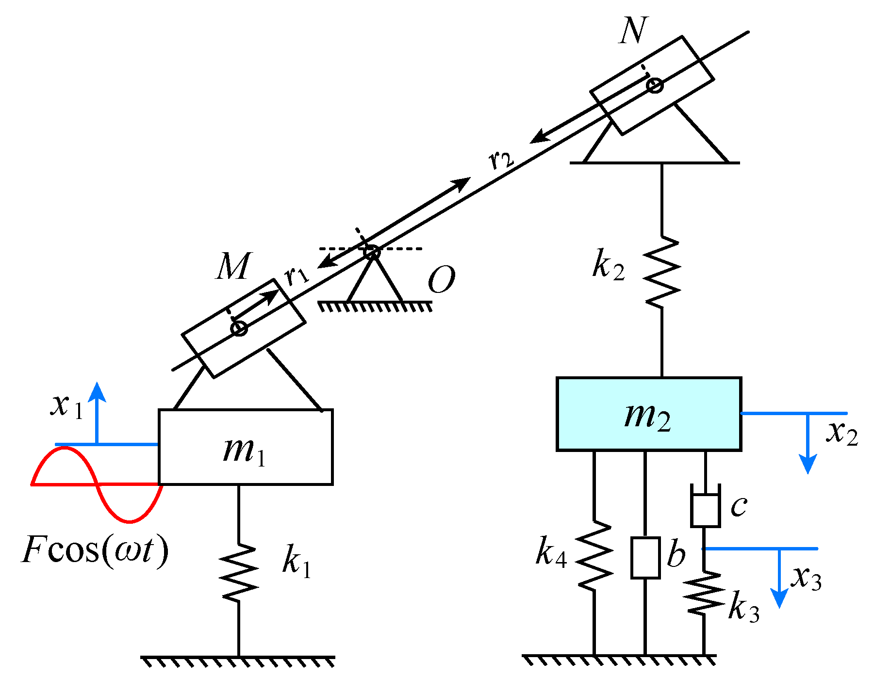
Since many vibration control devices, such as air springs and metal rubber, have viscoelastic characteristics, the Maxwell three-element model is a typical model describing the viscoelastic characteristics. Therefore, this paper proposes a Maxwell-type DVA with lever, inerter, and grounded stiffness, as shown in Figure 1. The model has a fixed support lever frame between the primary system and the DVA, and its fulcrum is O. In a real installation, the lever fulcrum O can be fixed to the ground or other inertial frame of reference. The resistance arm and the power arm of the lever are and , respectively, which represent the distance between the lever fulcrum O and the articulated points M, N. The masses of the primary system and DVA are and , respectively. The stiffness coefficients of the primary system, DVA, the viscoelastic Maxwell model, and the grounded spring are , , , and , respectively. The inerter coefficient is b. The damping coefficient of viscoelastic Maxwell model is c. The displacements of the primary system and the DVA are and , respectively. The split point of the spring and damping in Maxwell model is . F and represent the excitation amplitude and frequency, respectively.
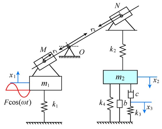
Figure 1.
The viscoelastic Maxwell-type DVA model with lever, inerter, and grounded stiffness.
It should be noted that the influence of the inerter depends significantly on the terminal locations. The amplification ratio of the lever increases means that the distance between the inerter position and the primary system increases, and then the force provided by the inerter will be amplified. We define as the amplification ratio of the lever mechanism. Ignoring the mass of the lever and the frictional resistance in the movement, according to Newton’s second law and lever principle, the governing equation of the system is established as
2.1. The Analytical Solution
We introduce the following parameter transformations
where and represent the natural frequencies of the primary system and the DVA, respectively. represents the damping ratio of the DVA. represents the mass ratio of the DVA to the primary system. and represent the corresponding stiffness ratios. f represent the ratio of the external excitation amplitude to the mass of the primary system. represent the ratio of the inerter coefficient to the mass of the DVA.
Equation (1) becomes
Suppose the form of steady state solutions is
Substituting Equation (3) into Equation (2) yields
where the symbol represents block matrix, with -th block , and all other blocks are zero matrices [45]. We have
For the convenience of derivation, we introduce the following parameters
The amplitude amplification factor A of the primary system can be written as
where
By setting the undamped denominator part of Equation (6) equal to zero, the dimensionless natural frequencies and of the coupled system can be obtained as
As can be seen from the Equation (8), the natural frequencies of the coupled system are affected by the stiffness ratio . The inappropriate stiffness ratio will make the natural frequencies imaginary numbers, which further leads to the instability of the coupled system.
2.2. Parameters Optimization
The primary structure in Figure 1 is subjected to harmonic excitation ; hence, the H optimization method is used to tuning the optimal parameters. For the given mass ratio , the amplification ratio L, and inerter–mass ratio , the aim is to determine four optimal parameters , , , and relating to , L, and , which minimize the maximum of A in Equation (6). The mathematical formula is as follows
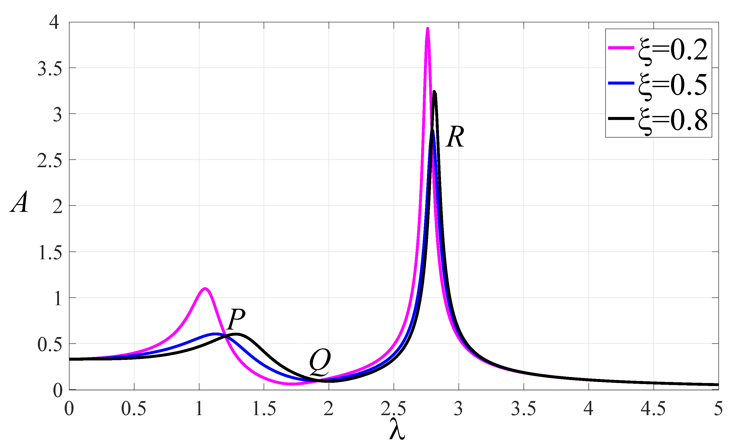
According to Equation (6), for given values of , , , , , L, the amplitude amplification factor A of the primary system can be plotted with respect to . In Figure 2, the normalized amplitude–frequency curves of model with several different damping ratios of 0.2, 0.5, and 0.8 are given. The curves all pass through three fixed points P, Q, and R, which are independent of the damping ratio.
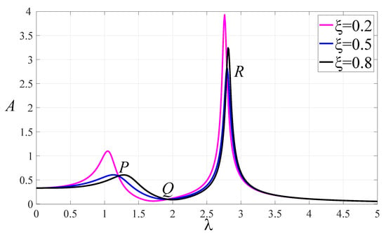
Figure 2.
The normalized amplitude–frequency curves of system with , , , , , .
The position of three fixed points in the amplitude frequency curve can be determined by the damping ratio and in Equation (6). Aided by the idea of fixed-point theory, the response values are equal when the damping ratio approaches zero or infinity in Equation (6)
We further obtain a cubic equation of
where
When , we can obtain
when , we can obtain
where
When and , the amplitude amplification factor of the primary system corresponding to P, Q and R are equal on the amplitude–frequency response curves, but the phase difference is , which is a positive and negative sign difference. Hence by Equations (12) and (13), we have
Let , and be the three roots of Equation (10), and the ordinates of P, Q and R are as follows.
The ultimate goal of H optimization is to minimize the maximum value of the amplitude–frequency curve, so we expect these three fixed points to be almost at the peak of the amplitude–frequency curve. In order to realize the optimal control effect, the optimal frequency ratio, stiffness ratio and damping ratio should be searched. It takes two steps to adjust the three fixed points to the same height.
The first step is to adjust the ordinate of P and R to the same height, i.e.,
Because of the value is independent of , Equation (15) gives rise to
Substituting Equation (16) into Equation (10), and solving Equation (10) for , yields
where . Thus, Equation (14) can be written as follows
In the second step, the ordinates of point P (or R) and point Q are adjusted to the same height, and two different optimal frequency ratio can be obtained.
Firstly, we consider . By substituting into Equation (16), the corresponding first optimal stiffness ratio can be obtained as
Then, we can obtain the response of the primary system at the fixed points, as follows
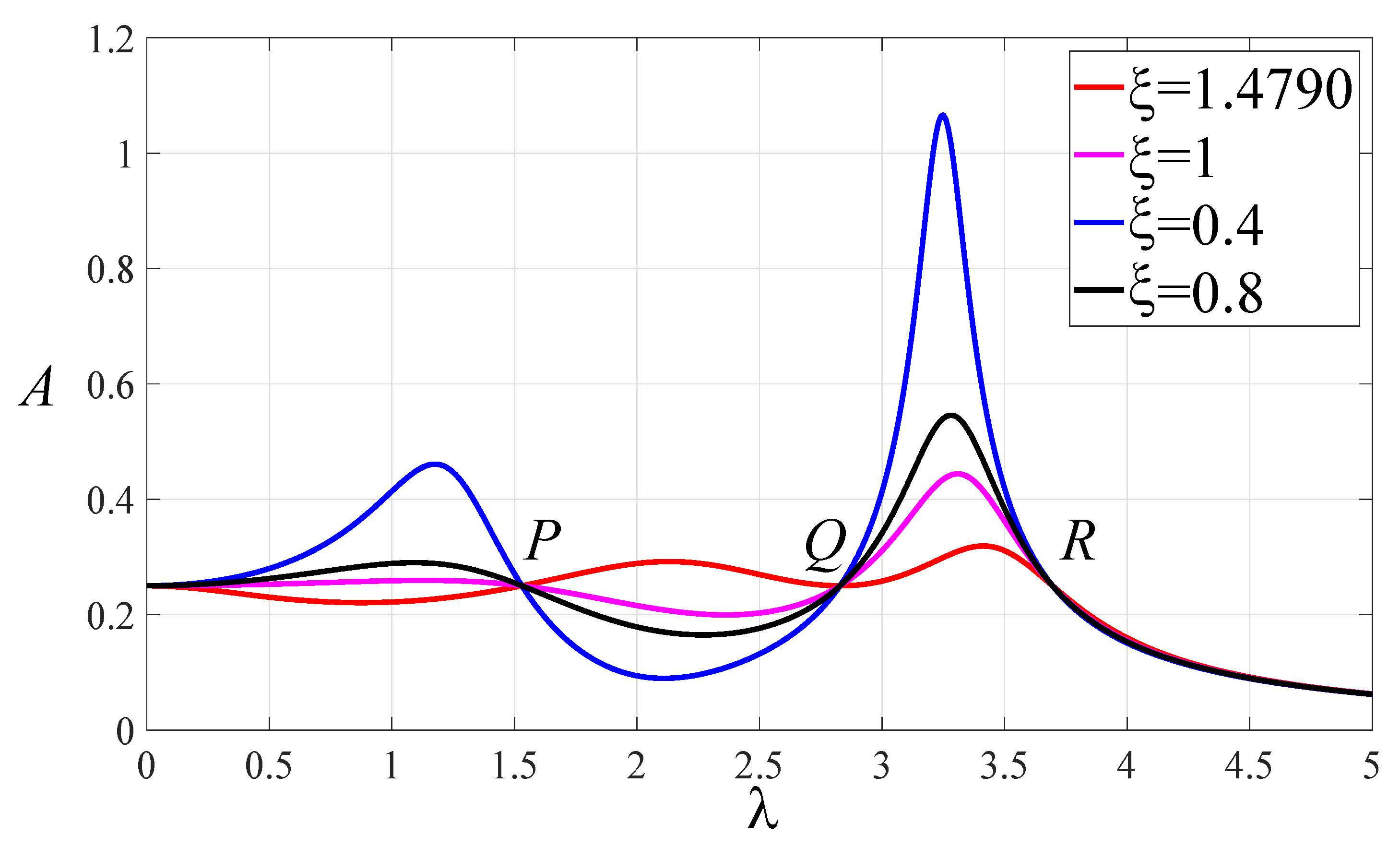
Thus, the optimal frequency ratio and possible maximum amplitude are obtained when the three fixed points are adjusted to the same height, as shown in Figure 3. At this time, changing the damping ratio can change the height of the resonance peak. The optimal damping ratio can be achieved by adjusting the two resonance peaks to the same height. It can be seen from Figure 3 that when the fixed points P, Q, and R are at the same height, the tangent of the frequency response curve at the Q point is almost horizontal. The abscissa of Q point has been calculated, and the approximate optimal damping ratio can be obtained according to the abscissa of Q point.
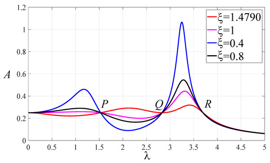
Figure 3.
The normalized amplitude–frequency curves of system with , , , , , .
Solving the above equation, we can obtain
Because the grounded stiffness in the model of this paper may be negative stiffness, according to the characteristics of negative stiffness devices, a pre-compression spring or pre-compression connecting rod is a common mechanism to realize negative stiffness characteristics, and pre-loading will cause pre-displacement of the system. We can use the pre-displacement as the amplitude at the fixed points. We further adjust the response values at the three fixed points to be equal to the response values when , namely
where
Solving Equation (24), all possible optimal stiffness ratios can be obtained
The appropriate grounded stiffness ratio should be selected on the premise of ensuring the stability of the system. Taking these five grounded stiffness into Equations (8), (21) and the first part of Equation (19), it is found that all these grounded stiffness ratios, except , will make the natural frequency of the coupled system or the optimal natural frequency ratio as imaginary number. So, is choosen as the optimal grounded stiffness ratio, namely
By analyzing the formula of the optimal grounded stiffness, we discover that the optimum grounded stiffness ratio will exhibit three different kinds of stiffness characteristics (positive, zero, and negative).
For the case 1, when is selected as the optimal frequency ratio, all optimal parameters of the model are obtained as
Similarly, for the case 2, when is selected as the optimal frequency ratio, all optimal parameters of model are obtained as follows
Obviously, there are three possibilities for the value of , the grounded stiffness ratio can be negative, zero, or positive, namely
3. Analysis of the Working Ranges of Inerter in Different Conditions
Considering Equations (28) and (29), when the mass ratio is fixed, there are still adjustable parameters in the optimal parameters formulas, namely the inerter–mass ratio and the lever magnification ratio L. In the optimal design of DVA, the inerter–mass ratio exist the working range under the premise of ensuring the stability of the system. In addition, the inerter–mass ratio has different operating ranges for different stiffness ratios and .
3.1. The Working Range of Inerter
With the optimal stiffness ratios of and , the presented DVA may have multiple negative stiffness springs. Based on Equation (29), the working range of inerter–mass ratio should satisfy the optimal frequency ratio , optimal damping ratio , and the optimal grounded stiffness ratio . We can obtain the working range of inerter
for .
Furthermore, the working ranges of inerter in other situations can be calculated similarly, as shown in Table 1. The results show that when the coupling term of magnification ratio and inerter–mass ratio takes different values, and the working ranges of inerter are different.

Table 1.
The working ranges of inerter in different situations.
3.2. Response Characteristics of Primary System for Different Cases
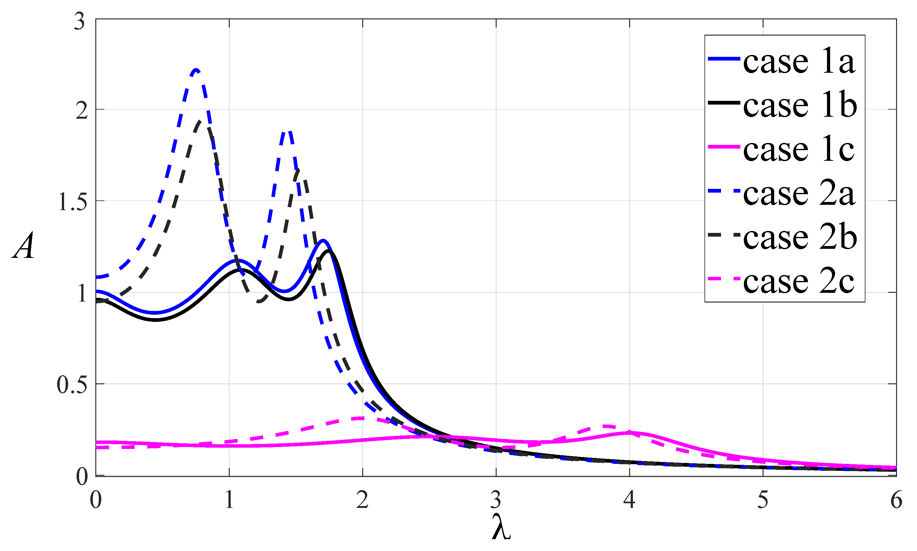
Based on Table 1, there are six ranges of inerter–mass ratio , and the parameters selected are shown in the Table 2. It should be noted that can use a range of values; here, we choose a value in the interval to calculate the optimal parameters. The normalized amplitude–frequency curves for different cases are shown in Figure 4. When , the control effect of DVA is the best for case 1c and the worst for case 1a. When , the damping effect of DVA is the best for case 2c and the worst for case 2a. In case 1c and case 2c, the corresponding grounded stiffness is positive. However, case 1c and case 2c require a high value of . Whether positive stiffness is selected as grounded stiffness should be based on the actual situation.

Table 2.
The parameters of the system for different cases.
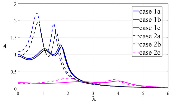
Figure 4.
The normalized amplitude–frequency curves for different cases.
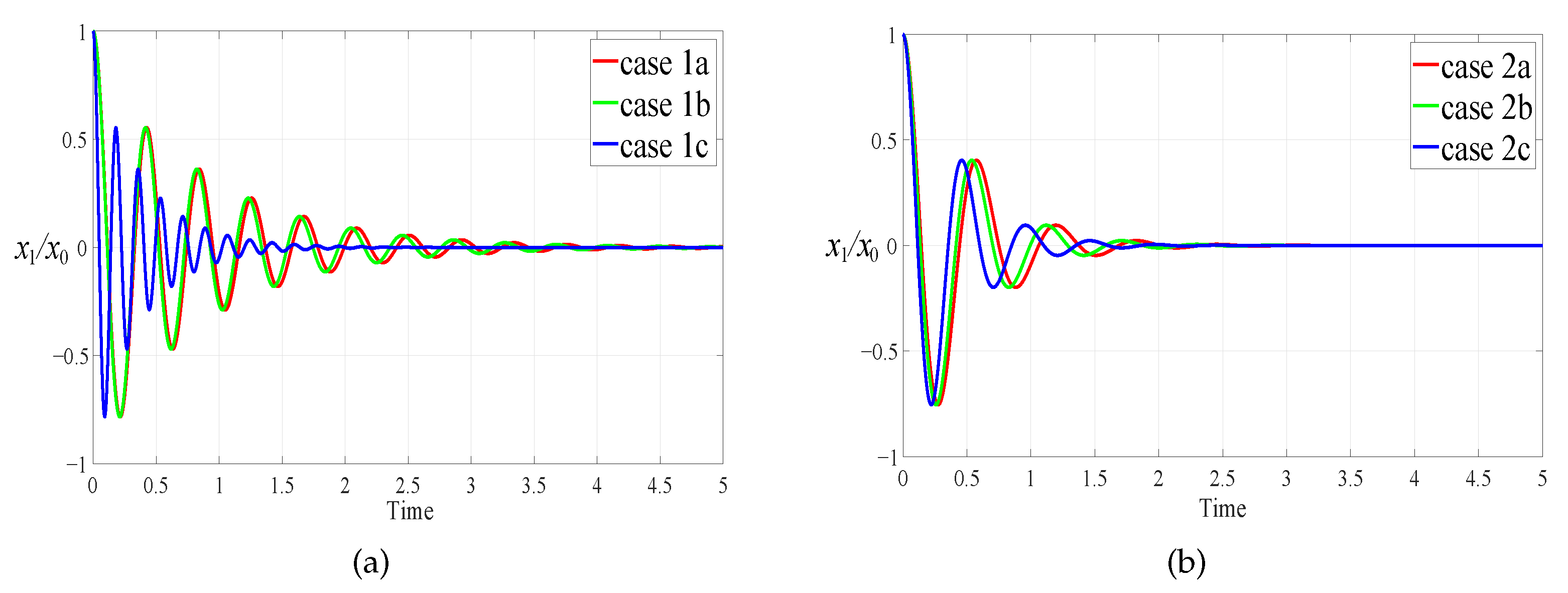
To gain the optimal reduction vibration effect of the vibration absorber under different optimum grounded stiffness ratios, Figure 5 shows the dimensionless transient response of the primary system under the six sets of parameters in Table 2. The initial displacement is selected as . The fourth-order Runge-Kutta method with a fixed time step of is used for simulation. The primary system vibration attenuation speed under case 1c is obviously faster than that of the other cases. In all cases, shimmy will not occur after the system is stable.
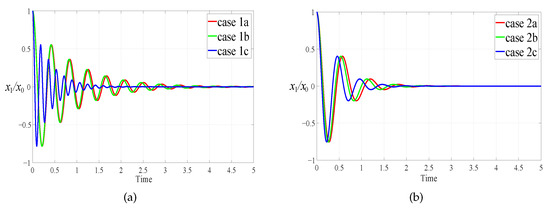
Figure 5.
Transient response to initial displacement : (a) . (b) .
4. The Influence of System Parameters on Response Characteristics
4.1. The Relationship between System Parameters and Optimal Parameters
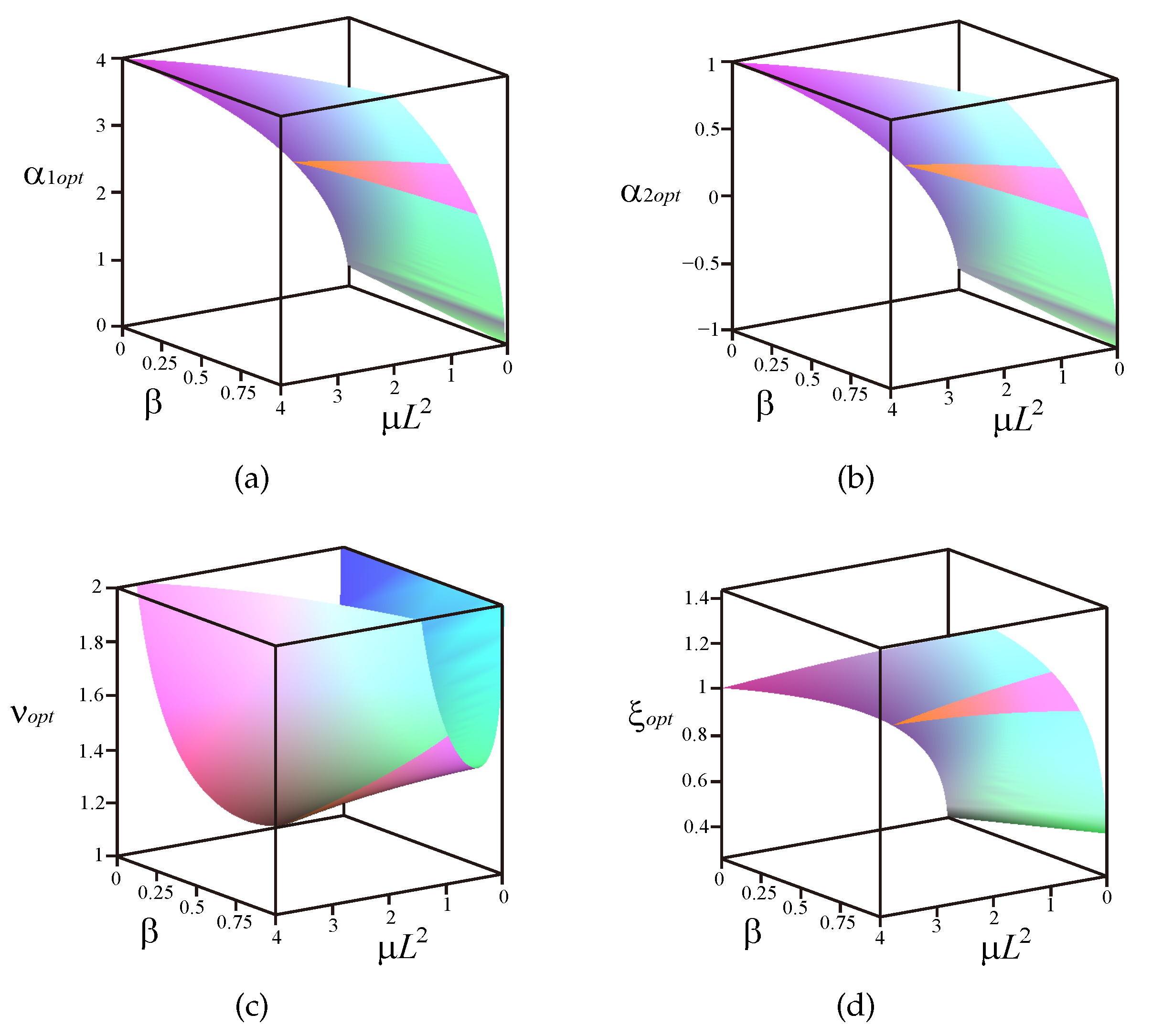
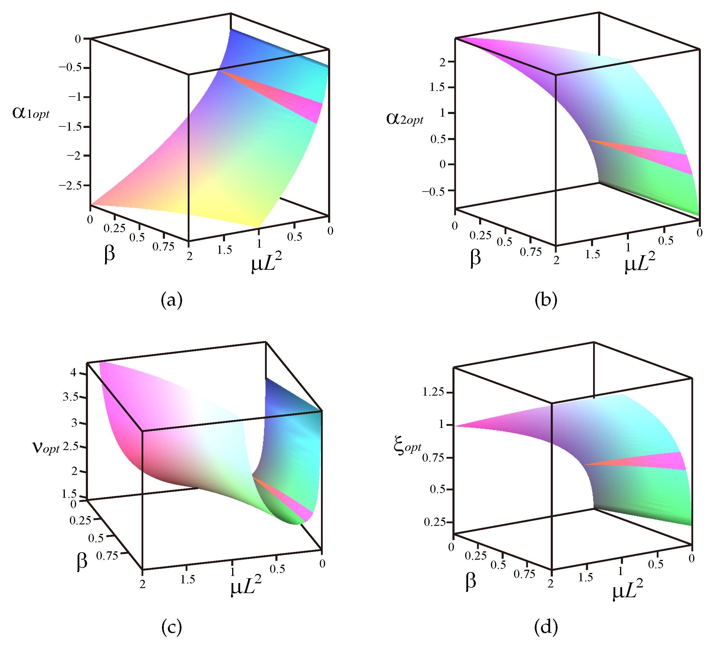
Considering the needs of practical engineering applications, we give the relationship between the optimal parameters in Equations (28) and (29) and the system parameters , L, and under different cases. The coupling term is taken as abscissa, and the inerter–mass ratio is taken as ordinate. It can be observed from Figure 6 and Figure 7 that the system is stable within the range of the selected parameters.
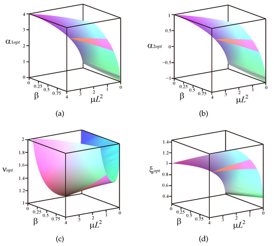
Figure 6.
The relationship between optimal parameters and system parameters when : (a) . (b) . (c) . (d) .
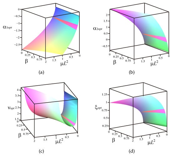
Figure 7.
The relationship between optimal parameters and system parameters when : (a) . (b) . (c) . (d) .
4.2. The Effect of Lever Mechanism on the Amplitude of Primary System
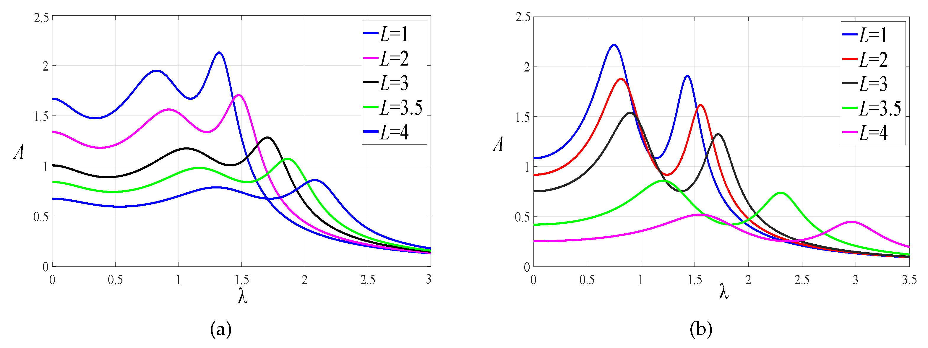
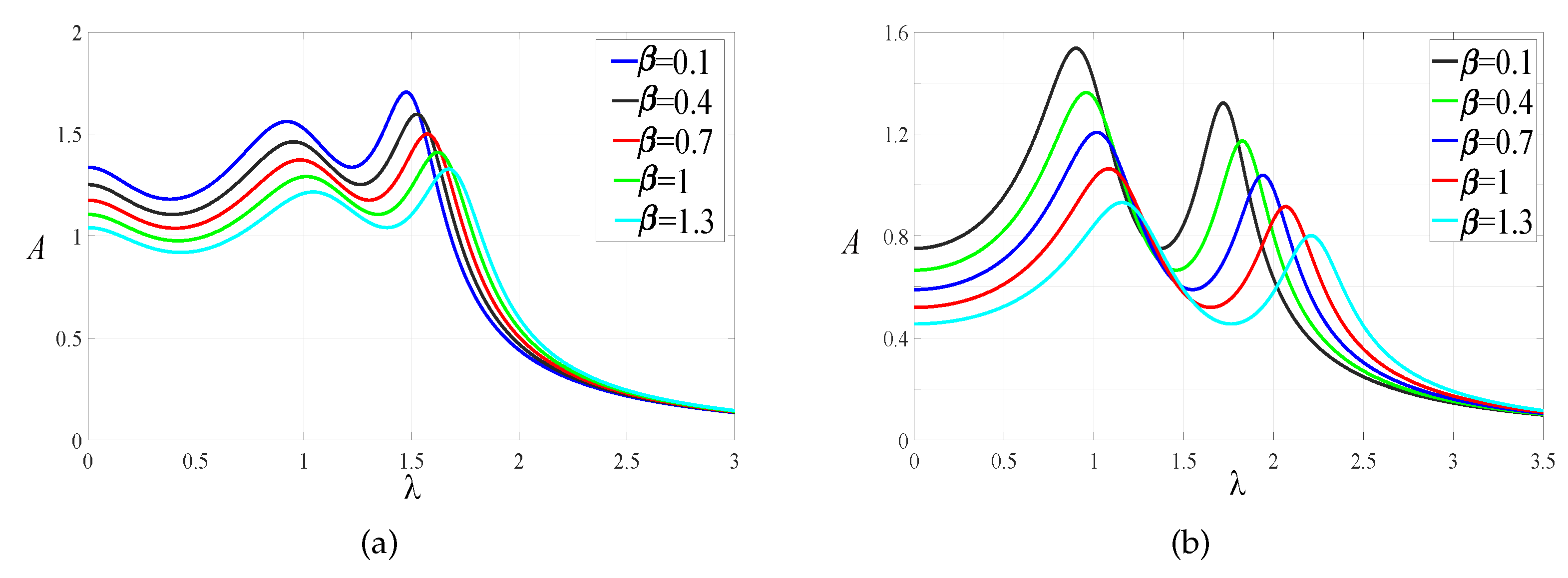
The mass ratio and inerter–mass ratio are selected for the two cases. The value of the amplification ratio L is greatly related to the maximum amplitude of the primary system. The amplitude–frequency response curves of the primary system with different values of L are given in Figure 8. As we can see, the larger the amplification ratio is, the lower the amplitude and the wider the distance between the two resonance peaks are.
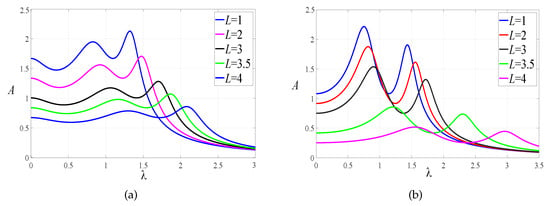
Figure 8.
The effect of the magnification ratio L on the response of the primary system: (a) . (b) .
4.3. The Effect of Inerter–Mass Ratio on the Amplitude of the Primary System
The mass ratio and magnification ratio are selected. The inerter–mass ratios are selected within the working range of inerter for the two cases. The normalized displacement amplitude–frequency response curves of the primary system with different values of are shown in Figure 9. We find that the larger the inerter–mass ratio is, the lower the amplitude and the better the effect are.
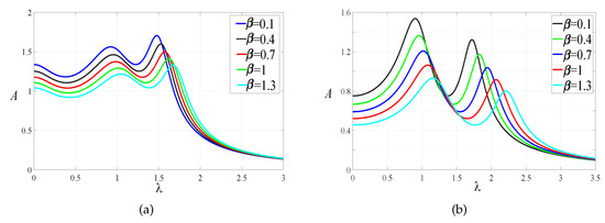
Figure 9.
The effect of the inerter–mass ratio on the response of the primary system: (a) . (b) .
5. Comparisons of the Control Performances
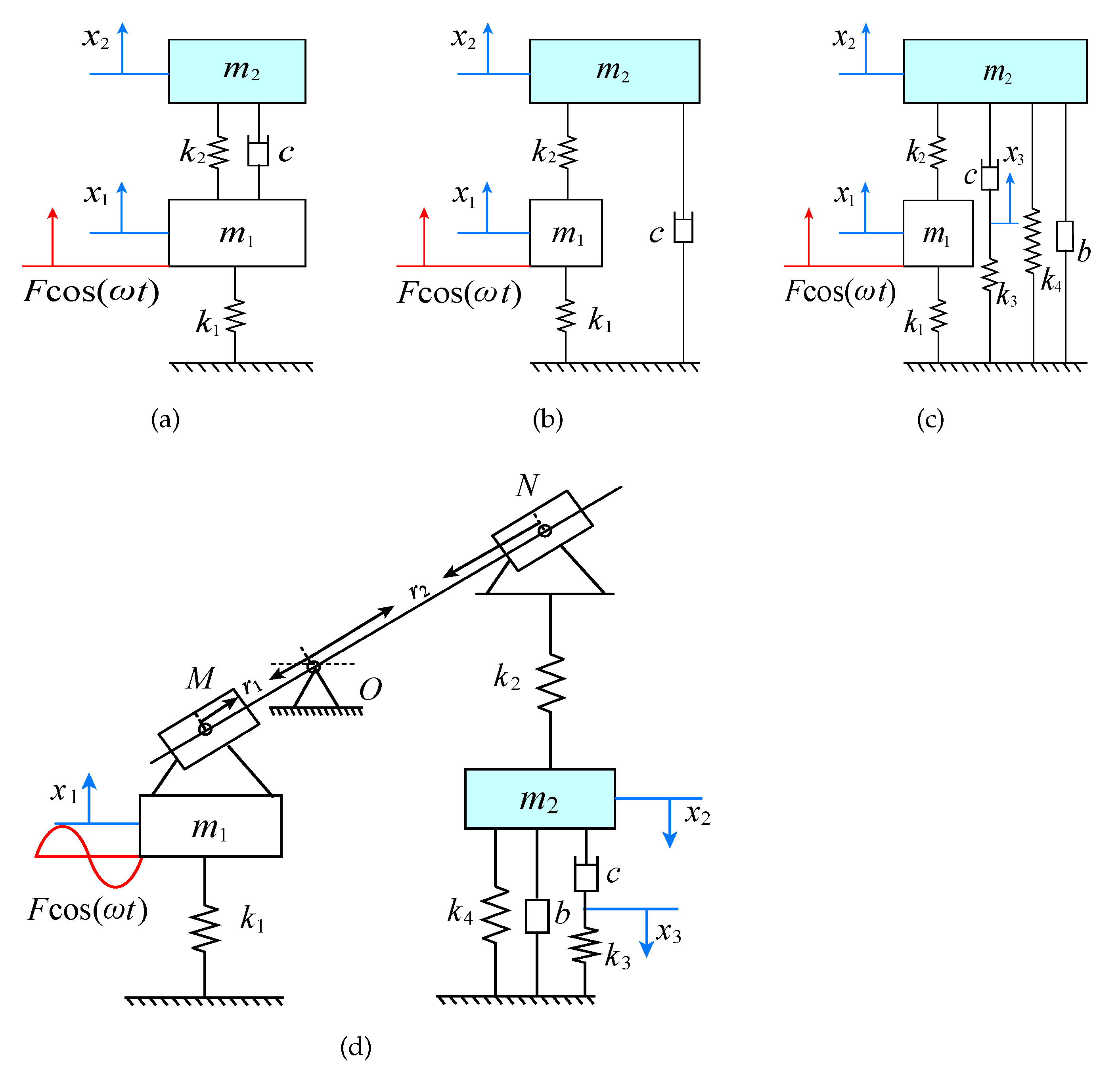
In this section, the results of cases 1c and 2c are compared with other classical DVAs. The classical Voigt-type DVA [2], grounded-type DVA [4], and the DVAs in Ref. [11] (IN-Maxwell-type DVA), Ref. [38] (L-grounded-type DVA) are shown in Figure 10. The model in Figure 10c shows a special case of our model, when , and the model in Figure 10d is a special case of our model when the stiffness coefficient of the viscoelastic Maxwell model is zero and the inerter coefficient is zero. The formulas of optimal parameters for each model are given in Table 3.
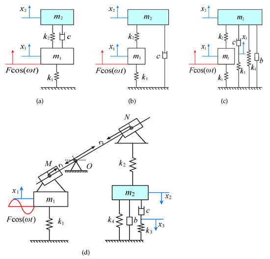
Figure 10.
The classical models of DVAs: (a) Voigt-type. (b) Grounded-type. (c) IN-Maxwell-type. (d) L-grounded-type.

Table 3.
The formulas of optimal parameters of DVAs.
5.1. Comparison with Other DVAs under Harmonic Excitation
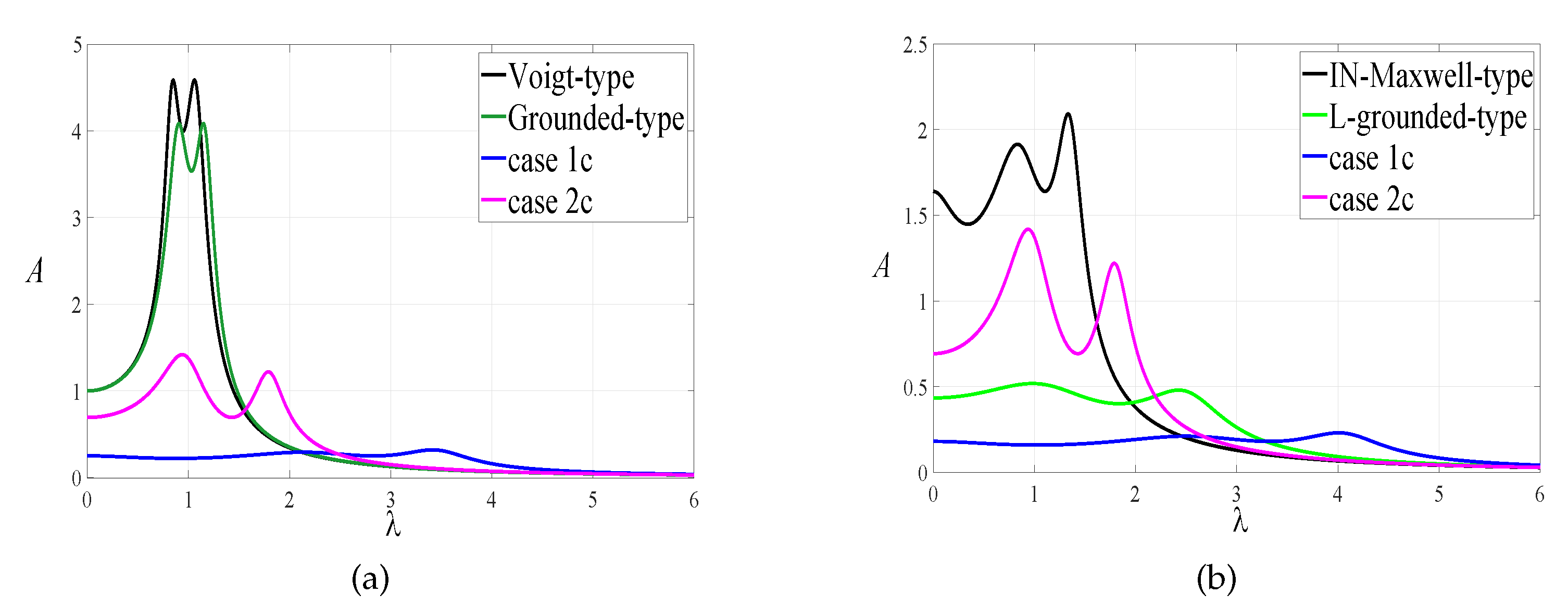
The mass ratio of each model takes . The inerter–mass ratio is selected for the IN-Maxwell-type DVA and this paper’s case 2c. The magnification ratio is selected for the L-grounded-type DVA and this paper’s case 1c. According to the optimal parameters formulas in Table 3, the normalized amplitude–frequency curves of each model under the optimal parameters are shown in Figure 11.
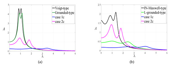
Figure 11.
Comparison of amplitude–frequency response curves with other DVAs: (a) Comparison of classical DVA with our results. (b) Comparison of IN-Maxwell-type, L-grounded-type DVA with our results.
The results show that the vibration reduction effect of proposed DVA is significantly better than the traditional Vogit-type and grounded-type DVAs under harmonic excitation. Compared with the IN-Maxwell-type and L-grounded-type DVAs, we can find that the lever and inerter have an effect of reducing the amplitude of the primary system and broadening the frequency band range. Moreover, the DVA control performance with positive grounded stiffness is better among these cases, especially when the stiffness coefficient of the viscoelastic Maxwell model and another grounded spring are positive simultaneously, while the performance drops slightly in the high frequency range. This performance degradation can be better explained by the change of natural frequencies, due to the addition of an inerter.
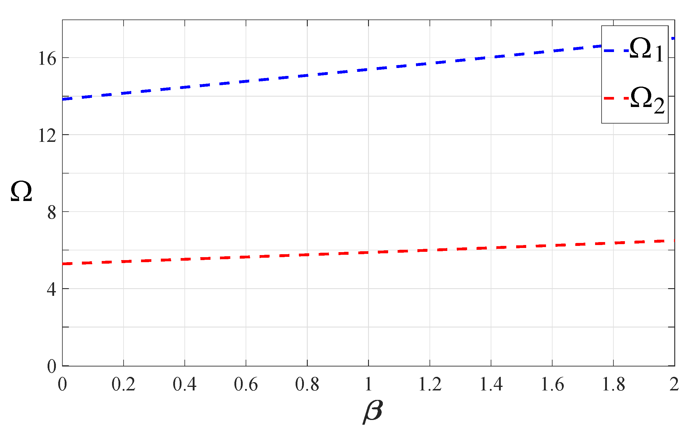
Based on Equation (8), the mass ratio and lever amplification ratio are selected. The variation of two dimensionless natural frequencies with inerter–mass ratio is shown in Figure 12. As the inerter–mass ratio increases, two natural frequencies move to the high frequency direction, which will lead to a slight decline in the vibration absorption performance of the proposed DVA with positive grounded stiffness in the high frequency direction.
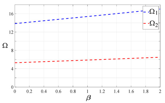
Figure 12.
The variation of the two dimensionless natural frequencies with inerter–mass under .
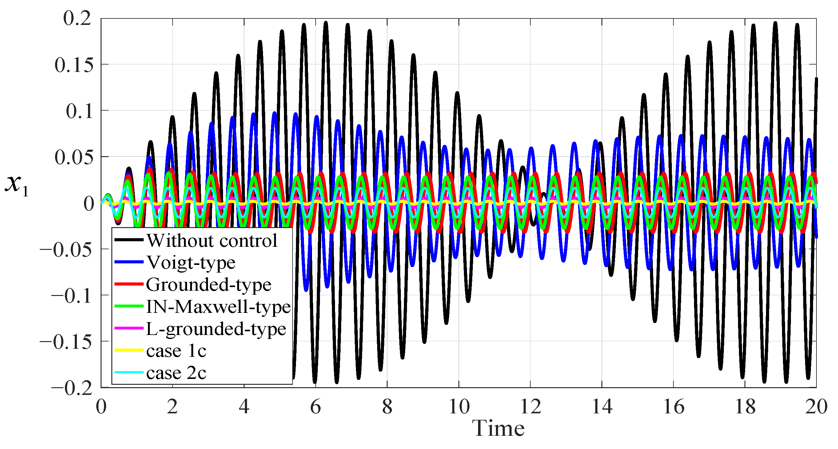
The harmonic force is applied to the primary system. The excitation amplitude is taken as , and the excitation frequency is taken as . Figure 13 presents the normalized displacement response of the primary structure equipped with DVAs and without control. The displacement response of the primary structure without inerter or lever vibration absorbers exhibits obvious fluctuation. By using the proposed vibration absorber, the large vibration of the primary system is alleviated.
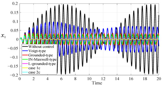
Figure 13.
Normalized displacement response of the primary system under a harmonic force excitation, when .
5.2. The Comparison with Other DVAs under Random Excitation
In civil and construction engineering, the system is usually excited by random excitation. Suppose that the primary system is subjected to random excitation with zero mean, with the power spectral density as . The power spectral density function of the displacement response of different models can be expressed as
where the subscripts V, G, , L, and represent the Voigt-type DVA, the grounded-type DVA, the IN-Maxwell-type DVA, the L-grounded-type DVA, and the DVA in this paper, respectively. Based on optimal parameters, the mean square responses of the primary systems of these DVAs can be derived as follows
where
with
The mean square response of the primary system under the optimal parameters can be separately calculated when .
where the , represent the mean squares of the presented DVA in case 1c, case 2c, respectively. is calculated at , and is calculated at .
The results show that, under the same initial parameters, the presented Maxwell DVA has the minimum mean square response, which shows that it has good vibration absorption performance under random excitation. Moreover, the proposed viscoelastic Maxwell DVA with two positive grounded stiffness shows better performance.
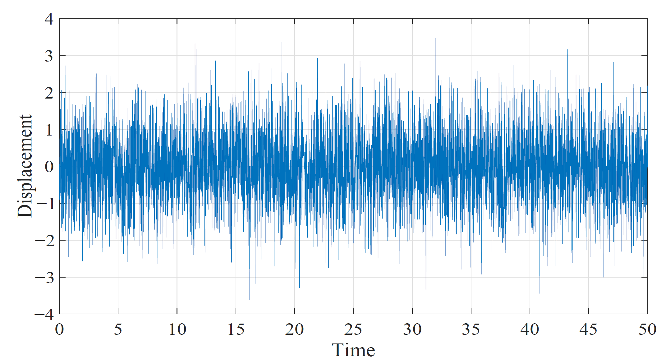
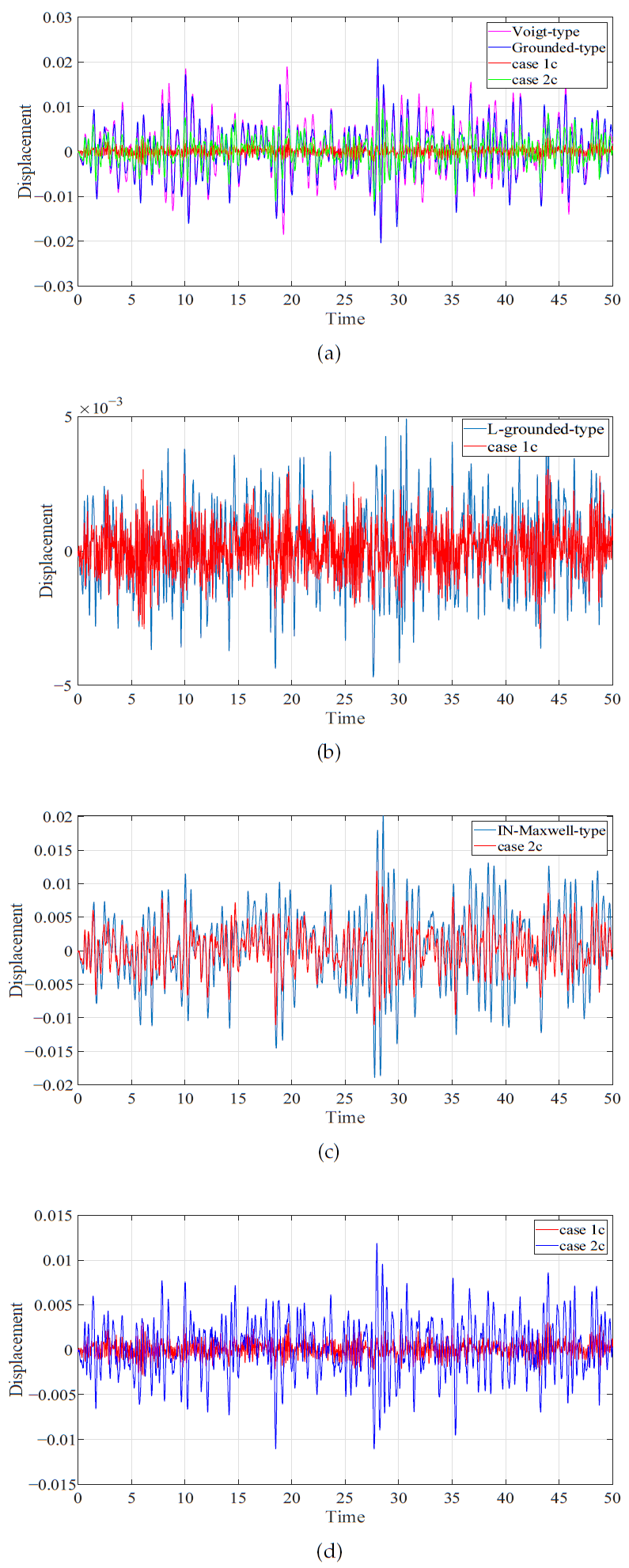
To simulate engineering reality, a random force excitation with zero mean value and unit variance is constructed in the , and its time history is shown in Figure 14. The mass and stiffness of the primary system is selected as , and the mass of DVA is . Then, the corresponding time history of different DVAs attached to primary system are shown in Figure 15. Table 4 summarizes the variances and decrease ratios of the the displacements of the primary system.
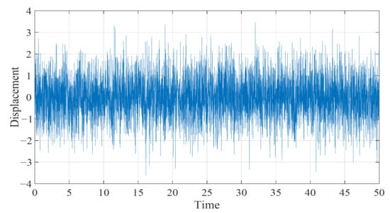
Figure 14.
Random force excitation.
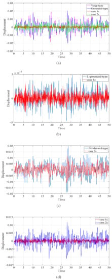
Figure 15.
Comparison of the time histories of the primary system with different DVAs: (a) Comparison of classical DVAs with our results. (b) Comparison of L-grounded-type DVA with case 1c. (c) Comparison of IN-Maxwell-type DVA with case 2c. (d) Comparison of case 1c with case 2c.

Table 4.
The variances and decrease ratios of the displacements of the primary system.
From Figure 15 and Table 4, it can be seen that, when the primary system is subjected to random excitation, the proposed DVA, under two sets of optimal parameters, has lower amplitude than classical DVAs. Compared with the IN-Maxwell-type DVA, it is found that under the same initial conditions , the proposed model for case 2c has better control performance under random excitation, which indicates that the lever element plays a role in vibration absorption. Compared with the L-grounded-type DVA, the model proposed in this paper for case 1c has a better control performance under the same initial conditions , which indicates that the inerter plays a role in vibration absorption. Furthermore, when is in the range of 1 to 4, the proposed DVA has satisfactory reduction vibration effect, and the DVA has two positive grounded stiffness.
Although the performance of the DVA, with negative grounded stiffness in this paper, may be worse than that of the DVA with positive grounded stiffness, sometimes it may need to be selected according to the actual engineering situation. The model and two groups of optimization formulas proposed in this paper can be alternately implemented in building protection and bridge seismic resistance.
6. Conclusions
A novel Maxwell DVA based on amplifying mechanism, inerter, and grounded stiffness is proposed. Aided by the H optimization principle, the optimal frequency ratio, stiffness ratio, and damping ratio are obtained. In the process of parameter optimization, two groups of different optimal parameters formulas are obtained according to different frequency ratios. The optimal grounded stiffness is discussed in different cases of positive and non-positive stiffness, respectively, and the working range of inerter under different conditions is determined. The effect of the selection of system parameters of the inerter within the optimal working range on the system response is further analyzed. The results show that, when the amplification ratio and mass ratio coupling reach a certain value, the stiffness coefficient of viscoelastic Maxwell model and another grounded stiffness are positive at the same time, and the vibration absorption effect is better in this case. Compared with traditional DVAs under harmonic and random excitation, it is found that proper selection of grounded stiffness, inerter–mass ratio, and amplification ratio can obviously reduce the vibration amplitude and greatly broaden the damping frequency band.
Beam structure is a typical structure in mechanical and civil engineering. Through the literature review, it can be found that multiple or distributed vibration absorbers are the current research hotspots. The model structure of this paper can provide a more accurate theoretical basis and calculation method for the optimization and control of the vibration absorber. In future research work, we will add the model structure in this paper to the design of multiple or distributed vibration absorbers to further improve the control performance and accuracy of vibration absorbers and provide a more effective solution for the vibration control of beam structure.
Author Contributions
Conceptualization: J.L. and X.Y.; methodology: J.L., T.G. and S.Z.; software: S.Z. and T.G.; validation: S.Z., X.Y. and T.G.; formal analysis: J.L. and T.G.; investigation: J.L. and X.Y.; writing—original draft preparation: T.G. and S.Z.; writing—review and editing: S.Z. and X.Y.; funding acquisition: J.L. All authors have read and agreed to the published version of the manuscript.
Funding
This research was supported by National Natural Science Foundation of China (grant No. 12272011) and also supported by National Key R&D Program of China (grant No. 2022YFB3806000).
Institutional Review Board Statement
Not applicable.
Informed Consent Statement
Not applicable.
Data Availability Statement
The data presented in this study are available on request from the corresponding author.
Acknowledgments
The authors would like to thank all the peer reviewers and editors for their valuable contribution to this work.
Conflicts of Interest
The authors declare no conflict of interest.
References
- Hermann, F. Device for Damping Vibrations of Bodies. U.S. Patent 0,989,958, 30 October 1909. [Google Scholar]
- Ormondroyd, J.; Den Hartog, J.P. The theory of the dynamic vibration absorber. J. Appl Mech. 1928, 50, 9–22. [Google Scholar]
- Asami, T.; Nishihara, O. Analytical and experimental evaluation of an air damped dynamic vibration absorber: Design optimizations of the three-element type model. J. Vib. Acoust. 1999, 121, 334–342. [Google Scholar] [CrossRef]
- Ren, M.Z. A variant design of the dynamic vibration absorber. J. Sound Vib. 2001, 245, 762–770. [Google Scholar] [CrossRef]
- Den Hartog, J.P. Mechanical Vibrations; McGraw-Hall Book Company: New York, NY, USA, 1947. [Google Scholar]
- Wong, W.O.; Fan, R.P.; Cheng, F. Design optimization of a viscoelastic dynamic vibration absorber using a modified fixed-points theory. J. Acoust Soc. Am. 2018, 143, 1064. [Google Scholar] [CrossRef] [PubMed]
- Batou, A.; Adhikari, S. Optimal parameters of viscoelastic tuned-mass dampers. J. Sound Vib. 2019, 445, 17–28. [Google Scholar] [CrossRef]
- Chang, T.L.; Lee, C.L. Numerical simulation of generalised Maxwell-type viscous dampers with an efficient iterative algorithm. Mech. Syst. Signal Process. 2022, 170, 108795. [Google Scholar] [CrossRef]
- Dai, J.; Xu, Z.D.; Gai, P.P.; Hu, Z.W. Optimal design of tuned mass damper inerter with a Maxwell element for mitigating the vortex-induced vibration in bridges. Mech. Syst. Signal Process. 2021, 148, 107180. [Google Scholar] [CrossRef]
- Shen, Y.J.; Peng, H.B.; Li, X.H.; Yang, S.P. Analytically optimal parameters of dynamic vibration absorber with negative stifness. Mech. Syst. Signal Process. 2017, 85, 192–203. [Google Scholar] [CrossRef]
- Wang, X.R.; He, T.; Shen, Y.J.; Shan, Y.C.; Liu, X.D. Parameters optimization and performance evaluation for the novel inerter-based dynamic vibration absorbers with negative stiffness. J. Sound Vib. 2019, 463, 114941. [Google Scholar] [CrossRef]
- Yao, H.L.; Cao, Y.B.; Wang, Y.W.; Wen, B.C. A tri-stable nonlinear energy sink with piecewise stiffness. J. Sound Vib. 2019, 463, 114971. [Google Scholar] [CrossRef]
- Salvatore, A.; Carboni, B.; Lacarbonara, W. Nonlinear dynamic response of an isolation system with superelastic hysteresis and negative stiffness. Nonlinear Dyn. 2021, 107, 1765–1790. [Google Scholar] [CrossRef]
- Chang, Y.P.; Zhou, J.X.; Wang, K.; Xu, D.L. A quasi-zero-stiffness dynamic vibration absorber. J. Sound Vib. 2021, 494, 115859. [Google Scholar] [CrossRef]
- Baduidana, M.; Kenfack-Jiotsa, A. Parameters optimization and performance evaluation for the novel tuned inertial damper. Eng. Struct. 2022, 250, 113396. [Google Scholar] [CrossRef]
- Zhang, M.J.; Xu, F. Tuned mass damper for self-excited vibration control: Optimization involving nonlinear aeroelastic effect. J. Wind Eng. Ind. Aerod. 2021, 220, 104836. [Google Scholar] [CrossRef]
- Zhang, M.J.; Song, Y.; Abdelkefi, A.; Yu, H.Y.; Wang, J.L. Vortex-induced vibration of a circular cylinder with nonlinear stiffness: Prediction using forced vibration data. Nonlinear Dyn. 2022, 108, 1867–1884. [Google Scholar] [CrossRef]
- He, M.X.; Tang, Y.; Ding, Q. Dynamic analysis and optimization of a cantilevered beam with both the acoustic black hole and the nonlinear energy sink. J. Int. Mat. Syst. Str. 2022, 33, 70–83. [Google Scholar] [CrossRef]
- Giaralis, A.; Petrini, F. Wind-induced vibration mitigation in tall buildings using the tuned mass-damper-inerter. J. Struct. Eng. 2018, 144, 08217004. [Google Scholar] [CrossRef]
- Chen, Q.J.; Zhao, Z.P.; Xia, Y.Y.; Pan, C.; Luo, H.; Zhang, R.F. Comfort based floor design employing tuned inerter mass system. J. Sound Vib. 2019, 458, 143–157. [Google Scholar] [CrossRef]
- Xu, K.; Bi, K.M.; Han, Q.; Li, X.P.; Du, X.L. Using tuned mass damper inerter to mitigate vortex-induced vibration of long-span bridges: Analytical study. Eng. Struct. 2019, 182, 101–111. [Google Scholar] [CrossRef]
- Wang, X.R.; Liu, X.D.; Shan, Y.C.; Shen, Y.J.; He, T. Analysis and optimization of the novel inerter-based dynamic vibration absorbers. IEEE Access. 2018, 6, 33169–33182. [Google Scholar] [CrossRef]
- Yu, H.Y.; Zhang, M.J.; Hu, G. Effect of inerter locations on the vibration control performance of nonlinear energy sink inerter. Eng. Struct. 2022, 273, 115121. [Google Scholar] [CrossRef]
- Brzeski, P.; Kapitaniak, T.; Perlikowski, P. Novel type of tuned mass damper with inerter which enables changes of inertance. J. Sound Vib. 2015, 349, 56–66. [Google Scholar] [CrossRef]
- Javidialesaadi, A.; Wierschem, N.E. Three-element vibration absorber-inerter for passive control of single-degree-of-freedom structures. J. Vib. Acoust. 2018, 140, 061007. [Google Scholar] [CrossRef]
- Li, J.; Gu, X.Q.; Zhu, S.T.; Yu, C.L.; Yang, X.D. Parameter optimization for a novel inerter-based dynamic vibration absorber with negative stiffness. J. Nonlinear Math. Phy. 2022, 29, 280–295. [Google Scholar] [CrossRef]
- Baduidana, M.; Wang, X.R.; Kenfack-Jiotsa, A. Parameters optimization of series-parallel inerter system with negative stiffness in controlling a single-degree-of-freedom system under base excitation. J. Vib. Control 2021, 28, 864–881. [Google Scholar] [CrossRef]
- Kun, Y.; Nyangi, P. H∞ optimization of tuned inerter damper with negative stiffness device subjected to support excitation. Shock Vib. 2020, 7608078. [Google Scholar]
- Alotta, G.; Failla, G. Improved inerter-based vibration absorbers. Int. J. Mech. Sci. 2020, 192, 106087. [Google Scholar] [CrossRef]
- Weber, F.; Borchsenius, F.; Distl, J.; Braun, C. Performance of numerically optimized tuned mass damper with inerter. Appl. Sci. 2022, 12, 6204. [Google Scholar] [CrossRef]
- Zhang, Z.; Lu, Z.Q.; Ding, H.; Chen, L.Q. An inertial nonlinear energy sink. J. Sound Vib. 2019, 450, 199–213. [Google Scholar] [CrossRef]
- Flannelly, W.G. Dynamic Antiresonant Vibration Isolator. U.S. Patent 3,322,379, 29 April 1967. [Google Scholar]
- Li, C.X.; Li, Q.S. Evaluation of the lever-type multiple tuned mass dampers for mitigating harmonically forced vibration. Int. J. Struct. Stab. Dyn. 2004, 5, 641–664. [Google Scholar] [CrossRef]
- Liu, C.C.; Jing, X.J.; Chen, Z.B. Band stop vibration suppression using a passive X-shape structured lever-type isolation system. Mech. Syst. Signal Process. 2016, 68–69, 342–353. [Google Scholar] [CrossRef]
- Zang, J.; Yuan, T.C.; Lu, Z.Q.; Zhang, Y.W.; Ding, H.; Chen, L.Q. A lever-type nonlinear energy sink. J. Sound Vib. 2018, 437, 119–134. [Google Scholar] [CrossRef]
- Cao, R.Q.; Wang, Z.J.; Zang, J.; Zhang, Y.W. Resonance response of fluid-conveying pipe with asymmetric elastic supports coupled to lever-type nonlinear energy sink. Appl. Math. Mech. 2023, 43, 1873–1886. [Google Scholar] [CrossRef]
- Yan, B.; Wang, Z.H.; Ma, H.Y.; Bao, H.H.; Wang, K.; Wu, C.Y. A novel lever-type vibration isolator with eddy current damping. J. Sound Vib. 2021, 494, 115862. [Google Scholar] [CrossRef]
- Shen, Y.J.; Xing, Z.Y.; Yang, S.P.; Sun, J.Q. Parameters optimization for a novel dynamic vibration absorber. Mech. Syst. Signal Process. 2019, 133, 106282. [Google Scholar] [CrossRef]
- Sui, P.; Shen, Y.J.; Yang, S.P.; Wang, J.F. Parameters optimization of dynamic vibration absorber based on grounded stiffness, inerter, and amplifying mechanism. J. Vib. Control 2021, 28, 3767–3779. [Google Scholar] [CrossRef]
- Shi, A.M.; Shen, Y.J.; Wang, J.F. Parameter optimization of a grounded dynamic vibration absorber with lever and inerter. J. Low Freq. Noise, Vib. Act. Control 2022, 41, 784–798. [Google Scholar] [CrossRef]
- Churchill, C.B.; Shahan, D.W.; Smith, S.P.; Keefe, A.C.; McKnight, G.P. Dynamically variable negative stiffness structures. Sci. Adv. 2016, 2, e1500778. [Google Scholar] [CrossRef] [PubMed]
- Qu, S.C.; Gao, N.; Tinel, A.; Morvan, B.; Romero-García, V.; Jean-Philippe, G.; Sheng, P. Underwater metamaterial absorber with impedance-matched composite. Sci. Adv. 2022, 8, eabm4206. [Google Scholar] [CrossRef]
- Basta, E.; Ghommem, M.; Emam, S. Flutter control and mitigation of limit cycle oscillations in aircraft wings using distributed vibration absorbers. Nonlinear Dyn. 2021, 106, 1975–2003. [Google Scholar] [CrossRef]
- Du, Y.; Zou, T.D.; Pang, F.Z.; Hu, C.; Ma, Y.; Li, H.C. Design method for distributed dynamic vibration absorbers of stiffened plate under different constraints. Thin-Walled Struct. 2023, 185, 110494. [Google Scholar] [CrossRef]
- Li, J.; Zhang, L.N.; Wang, D. Unique normal form of a class of 3 dimensional vector fields with symmetries. J. Differ. Equations 2014, 257, 2341–2359. [Google Scholar] [CrossRef]
Disclaimer/Publisher’s Note: The statements, opinions and data contained in all publications are solely those of the individual author(s) and contributor(s) and not of MDPI and/or the editor(s). MDPI and/or the editor(s) disclaim responsibility for any injury to people or property resulting from any ideas, methods, instructions or products referred to in the content. |
© 2023 by the authors. Licensee MDPI, Basel, Switzerland. This article is an open access article distributed under the terms and conditions of the Creative Commons Attribution (CC BY) license (https://creativecommons.org/licenses/by/4.0/).

