Article

Motion Control of Autonomous Underwater Helicopter Based on Linear Active Disturbance Rejection Control with Tracking Differentiator

1
Ocean College, Zhejiang University, Zhoushan 316021, China
2
Hainan Institute, Zhejiang University, Sanya 572025, China
*
Author to whom correspondence should be addressed.
Appl. Sci. 2023, 13(6), 3836; https://doi.org/10.3390/app13063836
Submission received: 2 February 2023 / Revised: 28 February 2023 / Accepted: 13 March 2023 / Published: 17 March 2023
(This article belongs to the Special Issue Advances in Applied Marine Sciences and Engineering)

Abstract

:
As a new disk-shaped autonomous underwater vehicle (AUV), the autonomous underwater helicopter (AUH) is devoted to subsea operations, usually diving into the seabed and docking with a subsea docking system. Due to the motion control’s performance, the AUH’s stability and steady-state accuracy are affected remarkably while docking. Moreover, considering the difficulties of hydrodynamic modeling of AUHs, the classical model-based control method is unsuitable for AUHs. Moreover, there is a large gap between the hydrodynamic simulation results and real situations. Hence, based on the data-driven principle, the linear active disturbance rejection control with a tracking differentiator (LADRC-TD) algorithm is employed for AUH depths and heading control. As the simulation experiments prove, LADRC and LADRC-TD have better anti-interference performance when compared with PID. According to the pool experiments, overshoots of the LADRC-TD are 20 cm and 3° for the depth control and heading control, respectively, which are superior to PID and LADRC. Meanwhile, the steady-state accuracy of the LADRC-TD is ±21 cm and ±2.5° for the depth and heading control, respectively, which is inferior to PID and the same as LADRC.

1. Introduction

Most of the marine resources, such as deep-sea manganese nodules, cobalt-rich hulls, and hydrothermal sulfides, exist on the seabed, so seabed development and exploration are one application trend of underwater robots. As a new disk-shaped autonomous underwater vehicle (AUV), the autonomous underwater helicopter (AUH) is dedicated to subsea operations, with many advantages, such as seabed residence, fixed-point hovering, high maneuverability, and anti-flow stability [1,2]. As to the work pattern (Figure 1), the AUH generally flies from one subsea docking system (SDS) to another, completing tasks that can include communications, equipment maintenance, and charging.
When the AUH needs to upload data to the sea surface or be charged, it approaches the SDS at a low speed [3], and the docking is then performed through the acoustic-optical guiding system. The controller’s performance of the AUH significantly affects its stability and success rate of docking onto an SDS.
As most AUVs have dynamic characteristics, such as tight coupling, strong nonlinear effects, and parameter uncertainty, there remains a difficulty in obtaining an accurate dynamic model. When considering the uncertainty of model parameters and the influence of unknown external perturbation, robust control methods, including the back-stepping and sliding mode controls, are adopted in AUV motion control. With the three-dimensional path following the error model being established based on the virtual guidance method, Wang [4] proposed a path following a robust control system using command-filtered back-stepping control, neural networks, and adaptive control techniques. Moreover, the authors from [5] proposed a back-stepping controller for tracking the desired depth of the AUV’s system, which lies on a vertical surface. At present, sliding mode control [6,7] has been widely studied and applied due to its simple design and easy implementation. Zhang [8] designed a terminal sliding mode variable structure control system with fast convergence speeds, high control precision, and strong robustness. Kantapon [9] developed a sliding mode heading control system for over-actuated, hover-capable AUVs that operate over a range of forward speeds. The proposed control system was also proven in field trials to enhance robust vehicle performance, even when subjected to external disturbances.
The hydrodynamic performance of an autonomous underwater vehicle (AUH) can be greatly affected by various factors, including the flow channel, external communication mechanism, external sensors, and other components. Although many hydrodynamic simulations of AUHs use simplified models [10,11,12], these models may not accurately capture the complex interactions between the vehicle and its environment. There is a large gap between the hydrodynamic simulation based on computational fluid dynamics (CFD) technology and the real situation; thus, it is unsuitable to use classical model-based control methods for the accurate control of AUHs [13,14]. Currently, researchers have gradually applied data-driven control methods to underwater vehicle control, such as model-free adaptive control (MFAC) [15], active disturbance rejection control (ADRC) [16], and fuzzy control [17] due to their advantages of having simple parameter adjustments and no model parameter limitations. Strictly speaking, the motion control of the AUH is a nonlinear system, and the system parameters will vary with the working depth and cruising speed. The authors currently use a neuroadaptive learning algorithm [18] and two new integral robust algorithms to deal with the nonlinear system with disturbance [19]. Furthermore, the authors introduced a global differentiator based on higher-order sliding modes (HOSM) and dynamic gains to solve the trajectory tracking problem [20] and proposed an improved active disturbance rejection control method for the output tracking of uncertain plants with unknown control directions [21].
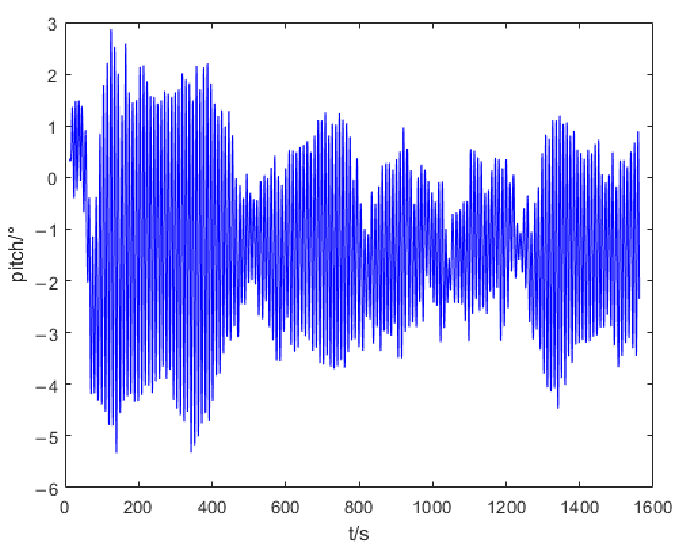
For the docking of AUHs, its accurate low-speed motion control is the basis. Considering the requirements of this task, more attention should be paid to the steady-state accuracy, overshoot, and anti-interference of AUHs. In view of the excellent anti-interference performance of ADRC, the authors plan to use the linear active disturbance rejection control with tracking differentiator (LADRC-TD) algorithm in this paper, aiming at realizing AUH motion control at a low speed. According to practical experience, the pitch angle does not show a dramatic change at low speeds. As exhibited in Figure 2, the pitch angle varies within ±5° when the AUH is moving at a speed of 0.2 m/s. Moreover, the simulation and pool experiments were conducted to verify the practicability and anti-interference performance of the LADRC-TD algorithm. This work’s main contribution is the application of the LADRC-TD to the heading and depth control of the AUH—a new disk-type AUV—and demonstrating its superiority over LADRC and PID through simulations and pool experiments.
Section 2 introduces the basic physical parameters and components of the Z-AUH, the software and hardware models of the control system, and the AUH’s dynamics and kinematics models. In Section 3, the algorithm principle and the controller design of the LADRC-TD are described. In Section 4, the effects of the PID, LADRC, and LADRC-TD algorithms are compared by using simulation experiments, and disturbing force and torque are added to the depth control and heading control, respectively. In Section 5, the excellent performance of the LADRC-TD is highlighted by the fixed-point pool experiment and dynamic experiment and is mirrored by the simulation results. Furthermore, due to the fixed-point experiment, the steady-state accuracy and overshoot of the PID, LADRC, and LADRC-TD in the depth control and heading control are also obtained. Finally, the conclusions are presented in Section 6.

2. Overview and Modeling of the AUH

2.1. Overview of the AUH

Inspired by the undersea stingray, our team developed a disk-shaped underwater vehicle, namely the AUH, which can take off, land on the seafloor, and hover at any altitude [22]. The following Table 1 exhibits the physical parameters and components of the Z-AUH.
The control software and hardware structures of the AUH are presented in Figure 4. The hardware of the control system comprises four parts: propellers, depth altimeter, IMU, and the main control panel, ARM I. MX6Q. Among them, the propellers are the executive components of the control system. As exhibited in Figure 3, there are six propellers, including two vertical propellers and four horizontal propellers. The vertical propellers are mainly responsible for the vertical movement and the pitch angle of the AUH, while the horizontal propellers are responsible for the movement and heading on a horizontal plane. The depth altimeter and IMU take charge of the detection and transmission of the current state information of the depth, height, and attitude angle, respectively. Moreover, the depth altimeter and IMU follow the RS232 and RS485 protocols, respectively. The main control panel accepts the state information sent back by the IMU and depth altimeter, making decisions, calculating the thrust of each propeller timely by the LADRC algorithm, and giving instructions to the propellers through the CAN protocol. In terms of the software, the main control panel is equipped with MOOS, a commonly used underwater robot control system. As presented in this paper, four program modules comprising Depth Height, IMUServer, Marine LADRC, and CANDevice, are employed to manage the depth altimeter, IMU, LADRC-TD controller, and propellers, respectively, and the subscribe–publish mechanism of MOOS is used. By combining the aforementioned four modules with the MOOSDB module, the AUH motion control software architecture is built.

2.2. Modeling of AUH

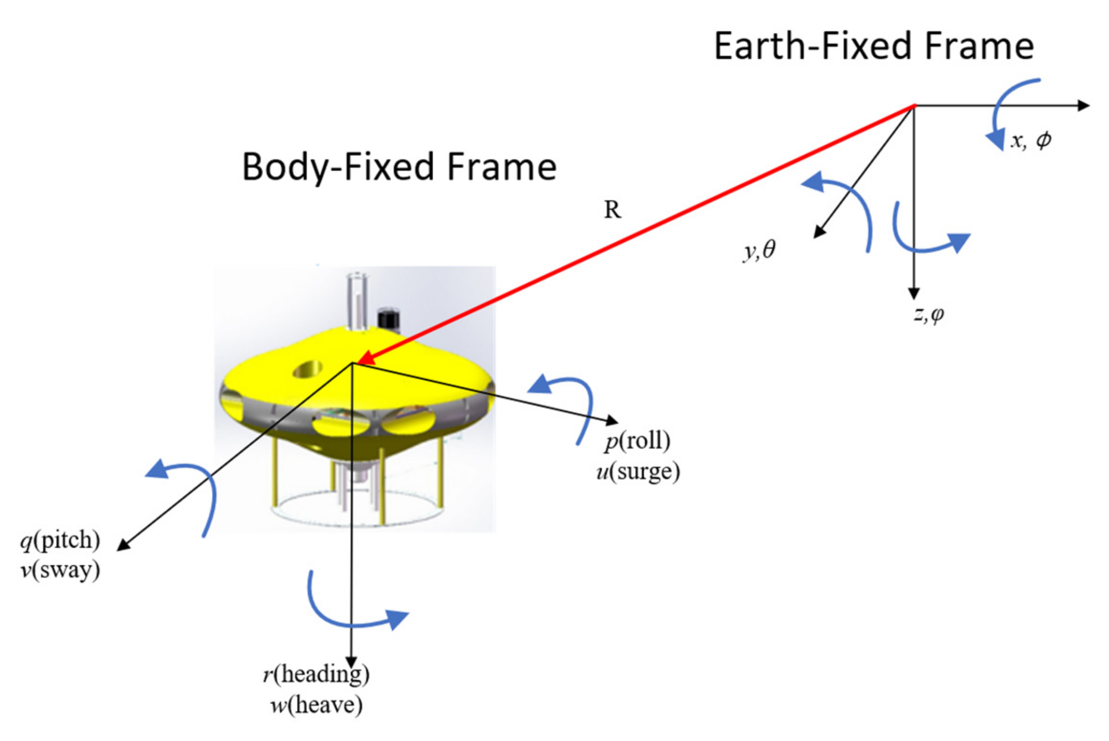
In order to establish the simple dynamic and kinematic models of the AUH, the body-fixed coordinate system and the inertial coordinate system are defined. Figure 5 exhibits the coordinate system of the AUH mentioned in this paper.
In Figure 5, the absolute linear position in the inertial coordinate system is ξ = [ x , y , z ] T , and the angular position is η = [ ϕ , θ , φ ] T . In the body-fixed frame, the origin is deemed as the center of mass of the AUH. Moreover, in the ontological coordinate system, the linear velocity is defined as V = [ u , v , w ] T , and the angular velocity is v = [ p , q , r ] T .
As the depth and heading control of the AUH at low speeds are mainly considered in this paper, the simplified kinematic and dynamic models are as follows [7].
X ˙ = u cos φ v sin φ Y ˙ = u sin φ + v cos φ Z ˙ = w Ψ ˙ = r
w ˙ = Z w m + Z w ˙ w Z w w m + Z w ˙ w w + 1 m + Z w ˙ ( τ Z + τ e n v ) + W B m + Z w ˙ φ ˙ = r r ˙ = N r I z + N r ˙ r N r r I z + N r ˙ r r + 1 I z + N r ˙ ( τ N + τ e n v ) + Y v ˙ X u ˙ I z + N r ˙ u v
where m refers to the mass of AUH; Z w ˙ and N r ˙ represent the hydrodynamic-added mass and hydrodynamic-added mass moment of inertia, respectively. Z w and N r are the linear damping coefficients; Z w w and N r r are the second-order damping coefficients. I z denotes the moment of inertia about the z-axis; τ Z and τ N are the thrust of the vertical propellers and the horizontal propellers, respectively; τ e n v refers to the environmental disturbing force. W represents gravity and B denotes buoyancy.

3. Design of AUH Controller

Han proposed ADRC [23], which involves disturbance estimation and compensation. The model uncertainty of the system can be considered as the internal disturbance, while the external disturbance is the total disturbance of the system. The nonlinear error feedback law includes a compensation component that estimates and compensates for the total disturbance in real time without distinguishing between the internal and external disturbances. This component simplifies the controlled object to a series of integrators, making it easy to construct an ideal controller. Essentially, this compensation component has an anti-interference effect. However, ADRC is initially in a nonlinear form and has numerous parameters, making parameter setting and implementation challenging in engineering.
LADRC [24] is an extension of ADRC, which uses a linear extended state observer (LESO) to estimate the state and disturbance of the system. It has a simpler structure than ADRC and is easier to analyze and set parameters.

3.1. LESO

The LESO is a linear observer that extends the state-space of the system to include the disturbance variables. It estimates the state and disturbance variables simultaneously, which improves the accuracy of the control system. LADRC has been applied in various fields, such as motor control, robotics, and power electronics. It is a promising control method for systems with uncertainties and disturbances.
In this paper, the controllers designed an all-adopt second-order LESO, and the same is true for the heading controller and depth controller. Hence, the design of the depth controller is taken as an example here.
First, ζ 1 , u 1 , b 1 are designed as below.
ζ 1 = Z w w     Z w w w w   +   τ e n v   +   W B m   +   Z w ˙ u 1 = τ Z b 1 = 1 m   +   Z w ˙
Afterwards, Equation (2) can be written as follows.
w ¨ = b 1 u 1 + ξ 1
where, ζ 1 refers to the generalized total disturbance of the system, including internal uncertainty and unknown external disturbance. Later, a second-order state-space expression can be obtained by extending ζ 1 to a state variable x 3 . In stable systems, it is generally assumed that the differential of x 3 is bounded and defined that x ˙ 3 = k .
y 1 = x 1 x ˙ 1 = x 2 x ˙ 2 = x 3 + b 1 u x ˙ 3 = k
In Equation (5), y 1 represents the AUH’s depth in the current state, which can be detected by a depth altimeter. The observer [25] is established based on the above state-space equation.
e = x ^ 1 y 1 x ^ ˙ 1 = x ^ 2 l 1 e x ^ ˙ 2 = x ^ 3 l 2 e + b 1 u x ^ ˙ 3 = l 3 e
In Equation (6), x ^ 1 , x ^ 2 , and x ^ 3 refer to the estimations of x 1 , x 2 , and x 3 , respectively. l 1 , l 2 , and l 3 represent the gains of the observer. To sum up, Equation (6) is the second-order extended state observer used by the depth controller. Moreover, to simplify the tuning process, the observer gains are parameterized as [24]
L = [ l 1 , l 2 , l 3 ] T = [ 3 w 0 , 3 w 0 2 , w 0 3 ] T
where w0 refers to the bandwidth of the system.
The linear state error feedback (LSEF) control law is mainly used to generate actual control signals and improve control accuracy by combining with the compensation quantity of the disturbance estimation above. In this paper, the PD control law is adopted, and the output of each propeller is calculated [24].
e 1 = v ¯ x ^ 1 e 2 = x ^ 2 u 0 = K p e 1 K d e 2 u = u 0 x ^ 3 b 1
where v ¯ refers to the desired signal and u denotes the output of the controller.
Generally, LADRC is composed of LESO and LSEF. However, classical LADRC methods often exhibit overshoots when working with large spans, which can be addressed by incorporating a tracking differentiator (TD). In order to mitigate this issue, this paper applies signal processing techniques and a TD in the control system’s input signal to enhance the transition process and improve control performance.

3.2. Tracking Differentiator

A tracking differentiator is a type of control algorithm used in control systems to estimate the derivative of the input signal of the system. It is a high-frequency filter that can accurately estimate the derivative of the input signal, even in the presence of noise and disturbances. The tracking differentiator can be used in various control applications, such as motion control, robotics, and aerospace systems. It is particularly useful when the input signal is noisy or when the system is subject to disturbances that can affect the accuracy of the derivative estimation.
In classical control theory, the differential signal for a given signal v is generally represented, as seen below [23].
y = w ( s ) v = s T s + 1 v = 1 T ( v 1 T s + 1 )
Equation (8) can be written as follows.
w ( s ) = s τ 2 s + 2 τ s + 1 = r a 2 ( s + r a ) 2 s
Running it on a computer, we have to discretize Equation (9) [23].
m 1 ( n ) = m 1 ( n 1 ) + m 2 ( n 1 ) h m 2 ( n ) = m 2 ( n 1 ) + r a 2 ( m 1 n v ¯ ( n ) ) 2 r a m 2 ( n 1 ) h
where h refers to the sampling step size and r a denotes the speed factor. The larger the r a , the faster the signal tracking speed. By combining LADRC with TD, the output of the controller LADRC-TD is u .
e 1 = m 1 x ^ 1 e 2 = x ^ 2 m 2 u 0 = K p e 1 K d e 2 u = u 0 x ^ 3 b 1
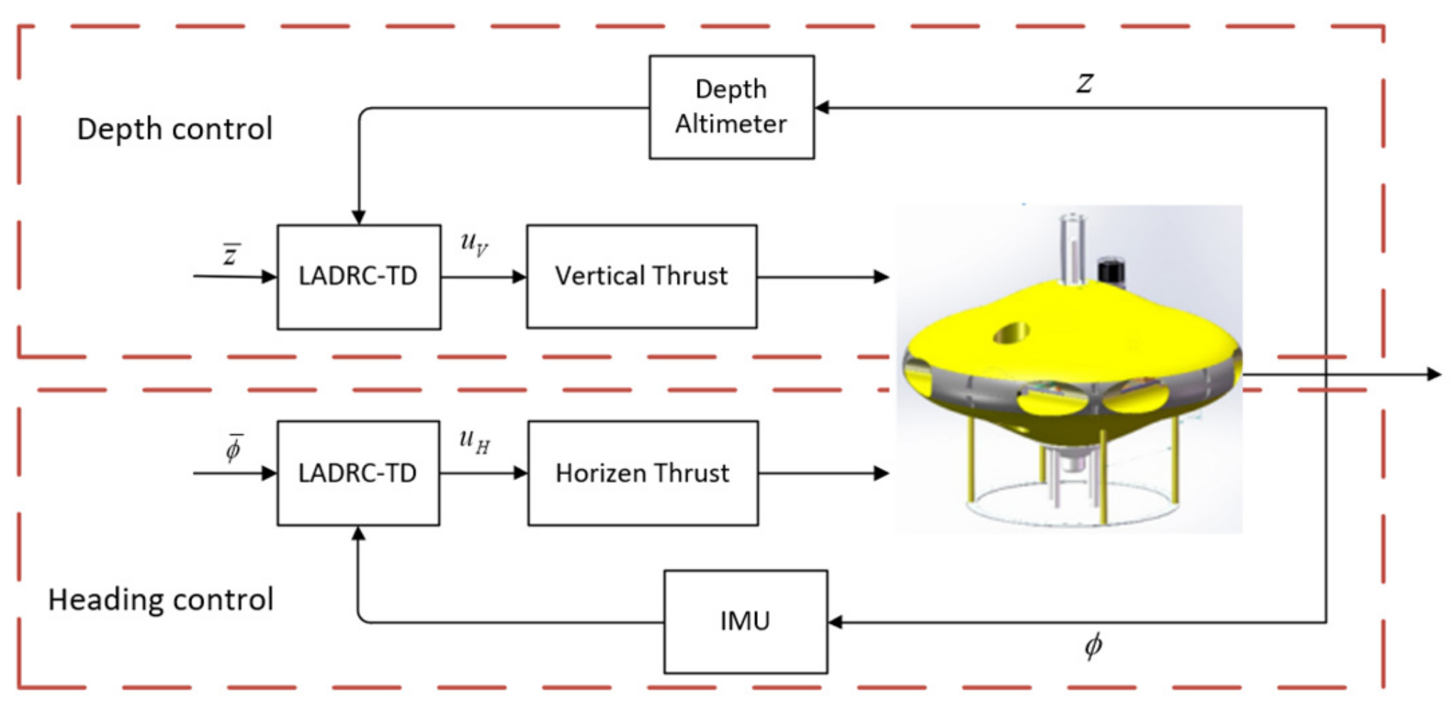
In summary, the block diagram of the LADRC-TD algorithm can be obtained (Figure 6).
In the case of the AUH, the dynamics can be decoupled into vertical and horizontal movements, where the vertical propellers control the depth of the vehicle, and the horizontal propellers control the heading. By decoupling the dynamics, it becomes easier to design control systems that can effectively control the vehicle’s motion in each direction. This approach helps to simplify the control system design and ensure that each subsystem is optimized for its specific task, resulting in improved overall control performance. In the control system described in the paper, the LADRC-TD is used for both the depth controller and the heading controller of the AUH. The control flow for the AUH can be summarized as follows (Figure 7).

4. Numerical Simulations

In the simulation experiments, the main objective was to evaluate the performance of the LADRC-TD algorithm for the heading and depth control of the AUH and to compare it with the LADRC and PID algorithms. The simulation conditions for all three algorithms were kept consistent to ensure the fairness of the experiments.

4.1. Heading Control Simulations

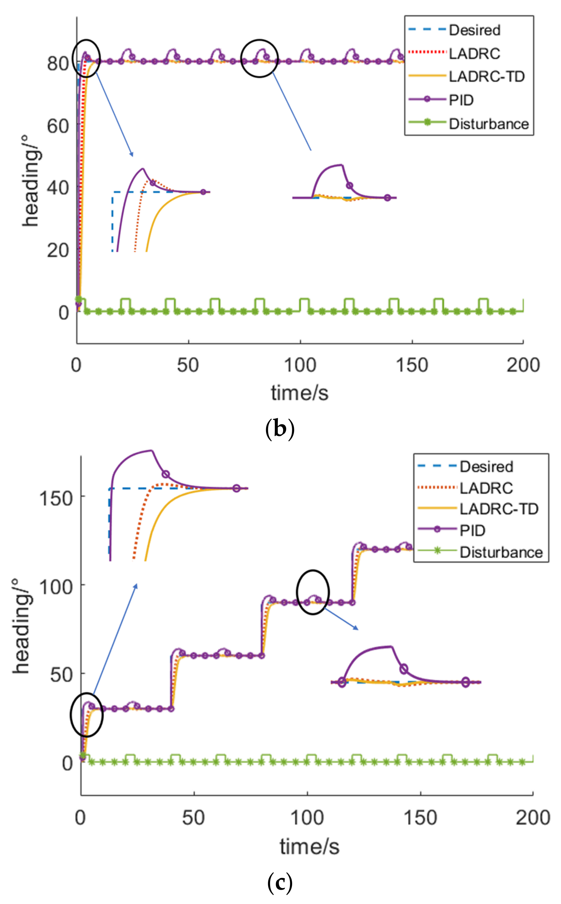
To reflect the anti-interference performance of the LADRC and LADRC-TD, 5 NM torque was added to the AUH as a disturbance, with a holding time of 4 s and a cycle of 20 s. In order to simulate the impact of the underwater turbulence on the AUH, a torque was applied that considered the asymmetry of the components outside the AUH shell, such as USBL and Iradia. However, it should be noted that the turbulence was not expected to be significant. Therefore, a torque with a reasonable amplitude of 5NM was selected for this simulation.
As presented in Figure 8a, a sinusoidal signal is used as the system input, aiming at testing the tracking performance of each algorithm. Moreover, PID exhibits large fluctuations in the heading tracking when under disturbance, while LADRC and LADRC-TD have small fluctuations, proving their certain anti-interference abilities. According to Figure 8b,c, both PID and LADRC show an overshoot under the step response. Although LADRC-TD has a slightly lower response speed, it shows no overshoot. Simultaneously, PID also exhibits an obvious fluctuation when under disturbance, and LADRC and LADRC-TD have similar performances, as shown in Figure 8a.

4.2. Depth Control Simulations

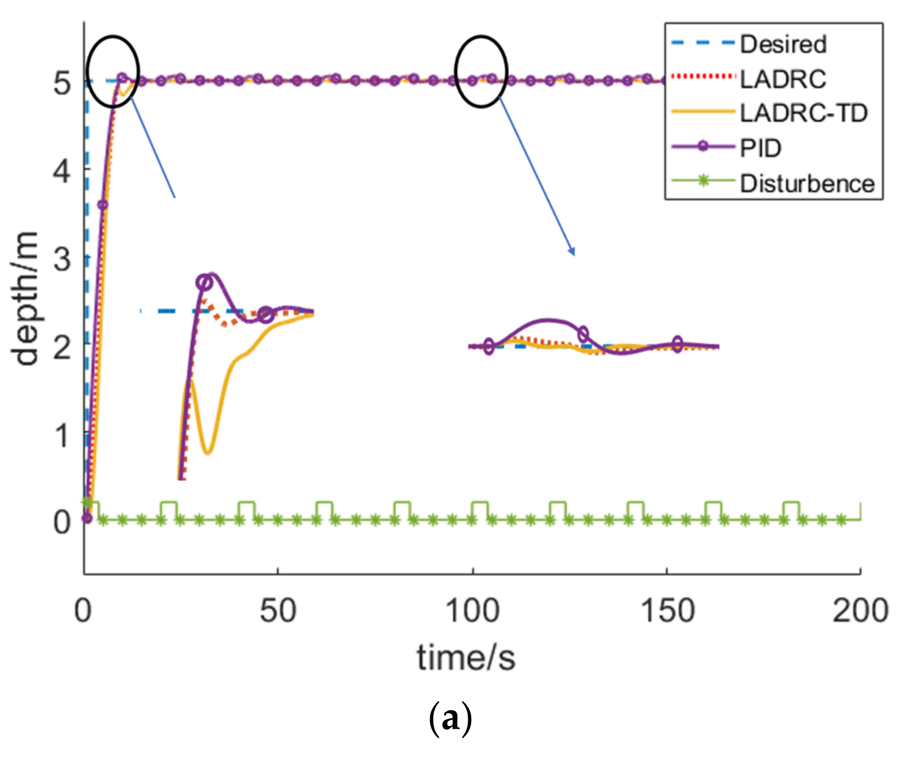
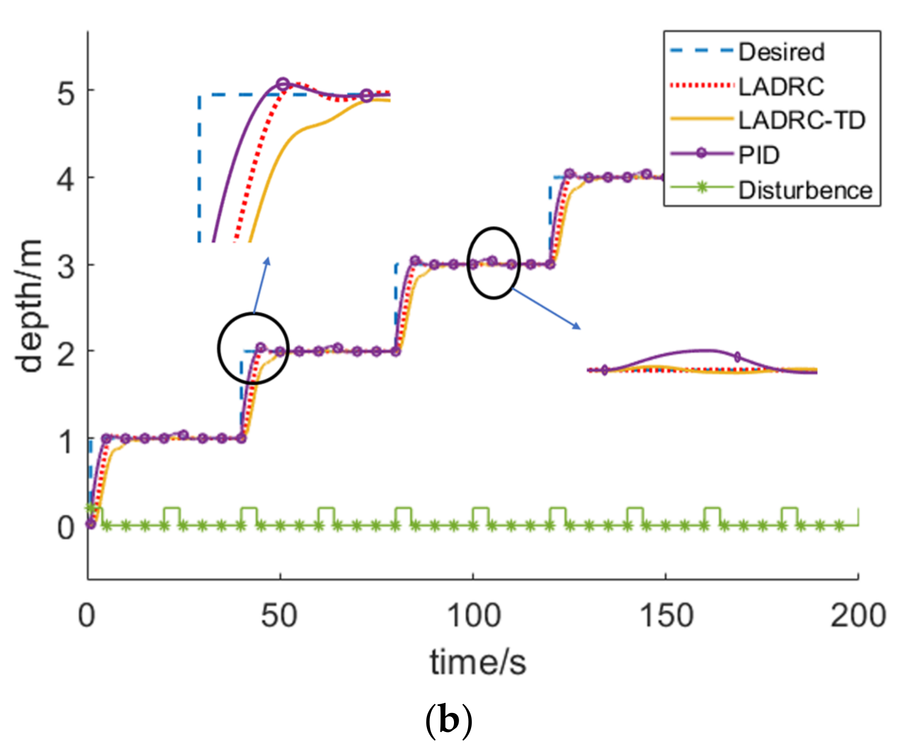
Similar to the previous simulation, the AUH was interfered with by a 10 N co-directional force, with a holding time of 4 s and a cycle of 20 s. In practice, the depth control of the AUH is mostly a step response and therefore, the long-span-step and multi-step simulations are performed in this section (Figure 9).
Similar to the heading control simulation, PID and LADRC demonstrated an overshoot in the multi-step responses. Moreover, LADRC and LADRC-TD exhibit small fluctuations, while PID fluctuates wildly under disturbance. Although the response speed of LADRC-TD is slightly lower, it shows no overshoot.
Because of the limitation of the simulations, the accuracy advantage of the LADRC-TD algorithm in the heading control and depth control cannot be reflected when compared with other algorithms. However, the simulations demonstrate that the anti-interference performance of LADRC-TD and LADRC is superior to PID in heading control and depth control. Moreover, LADRC-TD performs better than LADRC under the step response, as LADRC-TD shows no overshoot phenomenon. Therefore, the LADRC-TD algorithm is employed by the AUH for depth control and heading control in practical applications. In the next section, the corresponding steady-state accuracy of each algorithm can be obtained by virtue of the pool experiments.

5. Experiments and Results

5.1. Pool Experiments

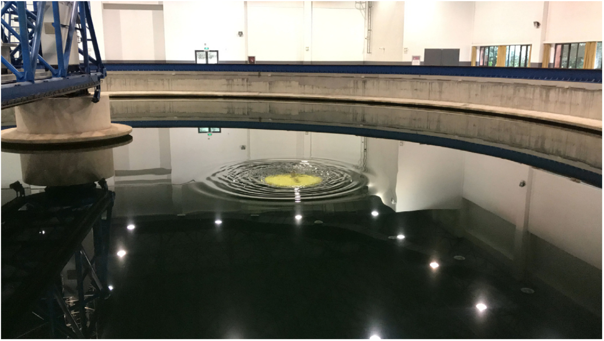
The experiments were conducted in a round pool with a diameter of 45 m and a depth of 6 m at the Ocean College of Zhejiang University (Figure 10). There were two experiments carried out: a fixed-point experiment and a dynamic experiment. During the fixed-point experiment, the AUH received signals for depth and heading adjustments and maintained its position in the horizontal plane while translating vertically. In the dynamic experiment, the AUH moved back and forth between two points at a low speed, and the outcomes of PID and LADRC-TD were compared.
In the tuning process, K p should be first tuned by increasing it gradually until an oscillation is observed. Then, K d will be increased until a small overshoot is achieved. Following this, K i is tuned to reduce steady-state accuracy. Finally, subtle adjustments are made to the parameters to optimize the dynamic response and steady-state performance. The tuning process for LADRC and LADRC-TD is similar. The bandwidth w 0 should be tuned first. In theory, a larger value of w 0 would result in better performance. However, the appropriate value of w 0 is dependent on factors such as the sampling frequency and the level of noise in the sensors. As the sampling frequency of the IMU and a depth altimeter are all set to 1 Hz, the optimal value of w 0 may be smaller than anticipated. Then, K p and K d should be tuned until the system is stable, which is similar to PID and finally, b 1 and r a should be fine-tuned to optimize the performance.
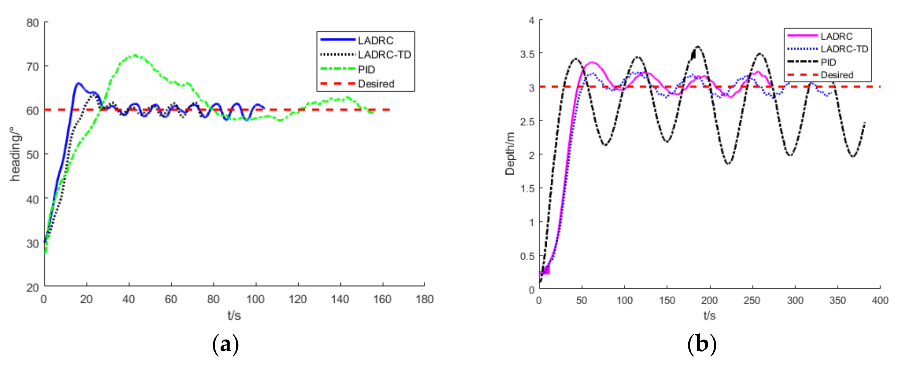
As exhibited in Figure 11a, for the heading control experiment, overshoot exits in all PID, LADRC, and LADRC-TD controllers, with overshoot amounts of 12°, 6°, and 3°, respectively. The response time of LADRC is slightly shorter than that of LADRC-TD, conforming to the simulation results. However, the response time of PID is significantly longer than that of LADRC and LADRC-TD, which differs from what is observed in the simulation. In practice, to reduce the oscillations, the parameter K p must be reduced, thus increasing the response time compared to the simulations. The steady-state accuracy of LADRC and LADRC-TD is about ±2.5°, and that of PID is ±3°.
As for the depth control shown in Figure 11b, the overshoot of PID is 43 cm, and the steady-state accuracy is ±1.1 m. The steady-state accuracy of LADRC is similar to that of LADRC-TD, namely approximately ±21 cm. However, the overshoot of LADRC is 41 cm, and that of LADRC-TD is merely 20 cm around.
In the dynamic experiment, the AUH needs to go back and forth between two points by three times at 0.2 m/s, thereby simulating the docking process when the AUH is close to the SDS.
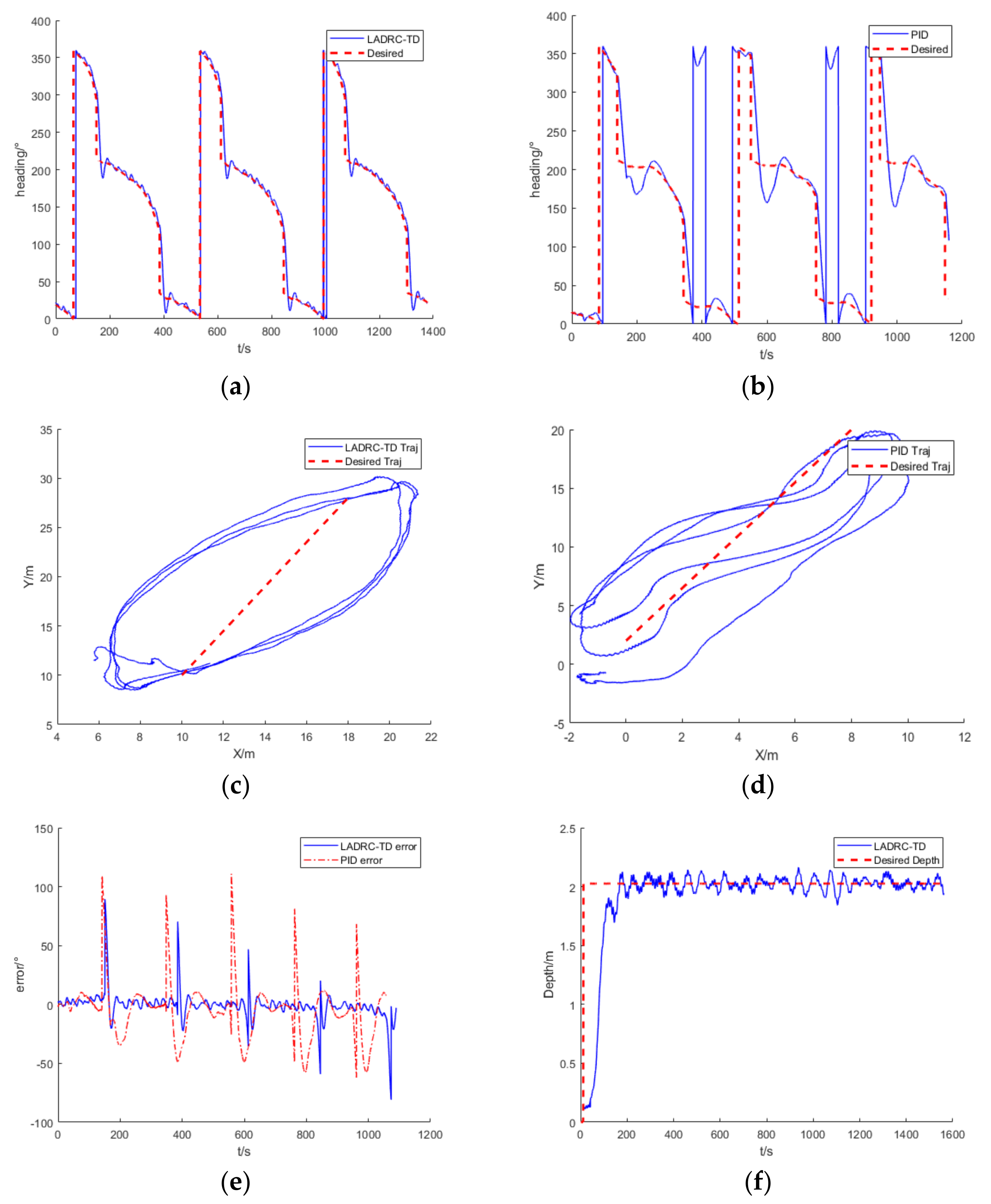
As observed from the comparison of the heading tracking of LADRC-TD and PID (Figure 12a,b), LADRC-TD has a better tracking performance, shorter response time, and lower overshoot. It is worth noting that the heading angle range is from 0 to 360 degrees, and when the angle turns from 300 to 380 degrees, it appears to be discontinuous (Figure 12b) because it first turns from 300 to 0 degrees and then from 0 to 20 degrees Due to the excellent heading tracking performance of the LADRC-TD, the three trajectories of the AUH show high similarity, as presented in Figure 12c. On the contrary, the three trajectories under PID control (Figure 12d) are chaotic because PID cannot accurately track the heading change in a timely manner. Although the trajectory of LADRC-TD is further away from the target trajectory than PID, this paper focuses on the heading tracking performance of different algorithms, which is different from the trajectory tracking.
As observed from the tracking error (Figure 12e), the PID heading tracking error is greater than LADRC-TD, the PID adjustment time is about 23 s longer than LADRC-TD, and the fluctuation of the adjustment process is more obvious when compared to LADRC-TD. During the movement of the AUH, the steady-state accuracy of depth control remains within ±21 cm (Figure 12f), demonstrating that the excellent anti-interference performance of LADRC-TD can meet the requirements of practical tasks.

5.2. Results

Based on the simulation and pool experiments, a comprehensive comparison is given to the control performances of PID, LADRC, and LADRC-TD in AUH depth control and heading control in this paper. Among them, PID has poor performance, a sizeable steady-state error in the depth and heading controls, and a worse anti-interference performance when compared to LADRC and LADRC-TD. LADRC demonstrates a performance between the LADRC-TD and PID. The steady-state accuracy and anti-interference of LADRC and LADRC-TD are almost the same. As LADRC-TD is added with tracking differentiation, the overshoot decreases, and the response time is slightly increased by approximately 2 s. However, more attention was paid to the accuracy, overshoot, and anti-interference at low speeds of the algorithms. As discovered, the response time of the LADRC-TD algorithm fully meets the task requirements. Table 2 summarizes the results of each algorithm in the simulations and the fixed-point experiment. In addition, the AUH performed PID and LADRC-TD in the dynamic experiment. As demonstrated, LADRC-TD has excellent dynamic depth-keeping performance and superior heading tracking performance compared to PID.

6. Conclusions

Aiming at the accurate motion control of an AUH at low speed, this paper focuses on overshoot, steady-state accuracy, and the anti-interference of an AUH’s heading and depth control, which is the basis for docking the AUH onto an SDS. Moreover, based on the data-driven principle, the LADRC-TD algorithm was adopted to resolve the problem in this paper’s hydrodynamic modeling of the AUH. By adding differential tracking to the classical LADRC algorithm, the excellent anti-interference performance of classical LADRC can be obtained, and the overshoot of the system can be reduced. According to the simulations and pool experiments, the following conclusions are drawn:
  • The LADRC-TD algorithm has the least overshoot, namely 20 cm and 3° in the depth control and heading control, respectively, which is less than PID and LADRC.
  • According to the simulations, the anti-interference of LADRC-TD is better than PID and nearly the same as LADRC.
  • The steady-state error of LADRC-TD is ±21 cm and ±2.5° in the depth control and heading control, respectively, which is lower than PID and the same as LADRC.
As demonstrated, LADRC-TD has a better control effect than PID and LADRC. The next step is to solve the motion control problem of an AUH at 1 m/s. In practice, the pitch angle of the AUH undergoes significant changes at such speeds, which can lead to instability and negatively impact its cruising capabilities. Therefore, it is crucial to develop effective motion control strategies to mitigate the adverse effects of pitch angle variations and ensure stable and efficient operation of the AUH at 1 m/s.

Author Contributions

Conceptualization, H.L., X.A. and Y.C.; methodology, H.L., X.A. and Y.C.; software, H.L., X.A. and R.F.; validation, H.L., X.A. and R.F.; formal analysis, H.L. and X.A.; investigation, R.F.; resources, Y.C.; data curation, H.L.; writing—original draft preparation, H.L.; writing—review and editing, X.A. and Y.C.; visualization, H.L.; supervision, R.F.; project administration, X.A. and Y.C. All authors have read and agreed to the published version of the manuscript.

Funding

The study was supported financially by the National Natural Science Foundation of China (Grant No. 52001279), the National Key R & D Program of China (NO. 2017YFC0306100).

Acknowledgments

The authors would like to thank Zhikun Wang and other Ocean College people at Zhejiang University for their inspiration and helping experiments.

Conflicts of Interest

The authors declare no conflict of interest.

References

  1. Wang, Z.; Liu, X.; Huang, H.; Chen, Y. Development of an Autonomous Underwater Helicopter with High Maneuverability. Appl. Sci. 2019, 9, 4072. [Google Scholar] [CrossRef] [Green Version]
  2. Peng, S.; Yang, C.; Fan, S.; Zhang, S.; Wang, P.; Xie, Y.; Chen, Y. A Hybrid Underwater Glider for Underwater Docking. In Proceedings of the MTS/IEEE OCEANS 2013, San Diego, CA, USA, 10–13 June 2013; Volume 7. [Google Scholar]
  3. Cai, C.; Xu, B. Development and Test of a Subsea Docking System Applied to an Autonomous Underwater Helicopter. In Proceedings of the MTS/IEEE OCEANS 2022, Hampton Roads, VA, USA, 17–20 October 2022; Volume 7. [Google Scholar]
  4. Wang, J.; Wang, C.; Wei, Y.; Zhang, C. Three-Dimensional Path Following of an Underactuated AUV Based on Neuro-Adaptive Command Filtered Backstepping Control. IEEE Access 2018, 6, 74355–74365. [Google Scholar] [CrossRef]
  5. Gharesi, N.; Ebrahimi, Z.; Forouzandeh, A.; Arefi, M.M. Extended State Observer-Based Backstepping Control for Depth Tracking of the Underactuated AUV. In Proceedings of the 2017 5th International Conference on Control, Instrumentation, and Automation (ICCIA), Shiraz, Iran, 21–23 November 2017; pp. 354–358. [Google Scholar]
  6. Mat-Noh, M.; Mohd-Mokhtar, R.; Arshad, M.R.; Zain, Z.M.; Khan, Q. Review of Sliding Mode Control Application in Autonomous Underwater Vehicles. Indian J. Geo-Marine Sci. 2019, 48, 973–984. [Google Scholar]
  7. Du, P.; Yang, W.; Wang, Y.; Hu, R.; Chen, Y.; Huang, S.H. A Novel Adaptive Backstepping Sliding Mode Control for a Lightweight Autonomous Underwater Vehicle with Input Saturation. Ocean Eng. 2022, 263, 112362. [Google Scholar] [CrossRef]
  8. Zhang, Y.; Gao, L.; Liu, W.; Li, L. Research on Control Method of AUV Terminal Sliding Mode Variable Structure. In Proceedings of the 2017 International Conference on Robotics and Automation Sciences, Hong Kong, China, 26–29 August 2017; pp. 88–93. [Google Scholar]
  9. Tanakitkorn, K.; Phillips, A.B.; Wilson, P.A.; Turnock, S.R. Sliding Mode Heading Control of an Overactuated, Hover-Capable Autonomous Underwater Vehicle with Experimental Verification. J. F. Robot. 2018, 35, 396–415. [Google Scholar] [CrossRef]
  10. Chen, C.W.; Jiang, Y.; Huang, H.C.; Ji, D.X.; Sun, G.Q.; Yu, Z.; Chen, Y. Computational Fluid Dynamics Study of the Motion Stability of an Autonomous Underwater Helicopter. Ocean Eng. 2017, 143, 227–239. [Google Scholar] [CrossRef]
  11. An, X.; Chen, Y.; Huang, H. Parametric Design and Optimization of the Profile of Autonomous Underwater Helicopter Based on Nurbs. J. Mar. Sci. Eng. 2021, 9, 668. [Google Scholar] [CrossRef]
  12. Lin, Y.; Lin, Y.; Guo, J.; Li, H.; Wang, Z.; Chen, Y.; Huang, H. Improvement of Hydrodynamic Performance of the Disk-Shaped Autonomous Underwater Helicopter by Local Shape Modification. Ocean Eng. 2022, 260, 112056. [Google Scholar] [CrossRef]
  13. Du, P.; Huang, S.H.; Yang, W.; Wang, Y.; Wang, Z.; Hu, R.; Chen, Y. Design of a Disc-Shaped Autonomous Underwater Helicopter with Stable Fins. J. Mar. Sci. Eng. 2022, 10, 67. [Google Scholar] [CrossRef]
  14. Liu, Z.; Zhou, J.; Wang, Z.; Zhou, H.; Chen, J.; Hu, X.; Chen, Y. Research on an Autonomous Underwater Helicopter with Less Thrusters. J. Mar. Sci. Eng. 2022, 10, 1444. [Google Scholar] [CrossRef]
  15. Li, X.; Ren, C.; Ma, S.; Zhu, X. Compensated Model-Free Adaptive Tracking Control Scheme for Autonomous Underwater Vehicles via Extended State Observer. Ocean Eng. 2020, 217, 107976. [Google Scholar] [CrossRef]
  16. Li, H.; He, B.; Yin, Q. Fuzzy Optimized MFAC Based on ADRC in AUV Heading Control. Electronics 2019, 8, 608. [Google Scholar] [CrossRef] [Green Version]
  17. Wan, L.; Zhang, Y.; Sun, Y.; Li, Y. Thruster-AUV’s Motion Adjustment Method Based on Fuzzy Control. In Proceedings of the 2015 International Industrial Informatics and Conputer Engineering Conference, Xi’an, China, 10–11 January 2015; pp. 266–269. [Google Scholar]
  18. Yang, G.; Yao, J.; Dong, Z. Neuroadaptive Learning Algorithm for Constrained Nonlinear Systems with Disturbance Rejection. Int. J. Robust Nonlinear Control. 2022, 32, 6127–6147. [Google Scholar] [CrossRef]
  19. Yang, G. Asymptotic Tracking with Novel Integral Robust Schemes for Mismatched Uncertain Nonlinear Systems. Int. J. Robust Nonlinear Control. 2023, 33, 1988–2002. [Google Scholar] [CrossRef]
  20. Oliveira, T.R.; Estrada, A.; Fridman, L.M. Global and Exact HOSM Differentiator with Dynamic Gains for Output-Feedback Sliding Mode Control. Automatica 2017, 81, 156–163. [Google Scholar] [CrossRef]
  21. Teixeira, A.; Gouvea, J.A.; Zachi, A.R.L.; Rodrigues, V.H.P.; Oliveira, T.R. Monitoring Function-based Active Disturbance Rejection Control for Uncertain Systems with Unknown Control Directions. Adv. Control Appl. 2021, 3, e66. [Google Scholar] [CrossRef]
  22. Zhou, J.; Huang, H.; Huang, S.H.; Si, Y.; Shi, K.; Quan, X.; Guo, C.; Chen, C.; Wang, Z.; Wang, Y.; et al. AUH, a New Technology for Ocean Exploration. Engineering 2022. [Google Scholar] [CrossRef]
  23. Han, J. From PID to Active Disturbance Rejection Control. IEEE Trans. Ind. Electron. 2009, 56, 900–906. [Google Scholar] [CrossRef]
  24. Gao, Z. Active Disturbance Rejection Control: A Paradigm Shift in Feedback Control System Design. In Proceedings of the American Control Conference, Minneapolis, MN, USA, 14–16 June 2006; pp. 2399–2405. [Google Scholar]
  25. Gao, Z. Scaling and Bandwidth-Parameterization Based Controller Tuning. In Proceedings of the American Control Conference, Denver, CO, USA, 4–6 June 2003; pp. 4989–4996. [Google Scholar]
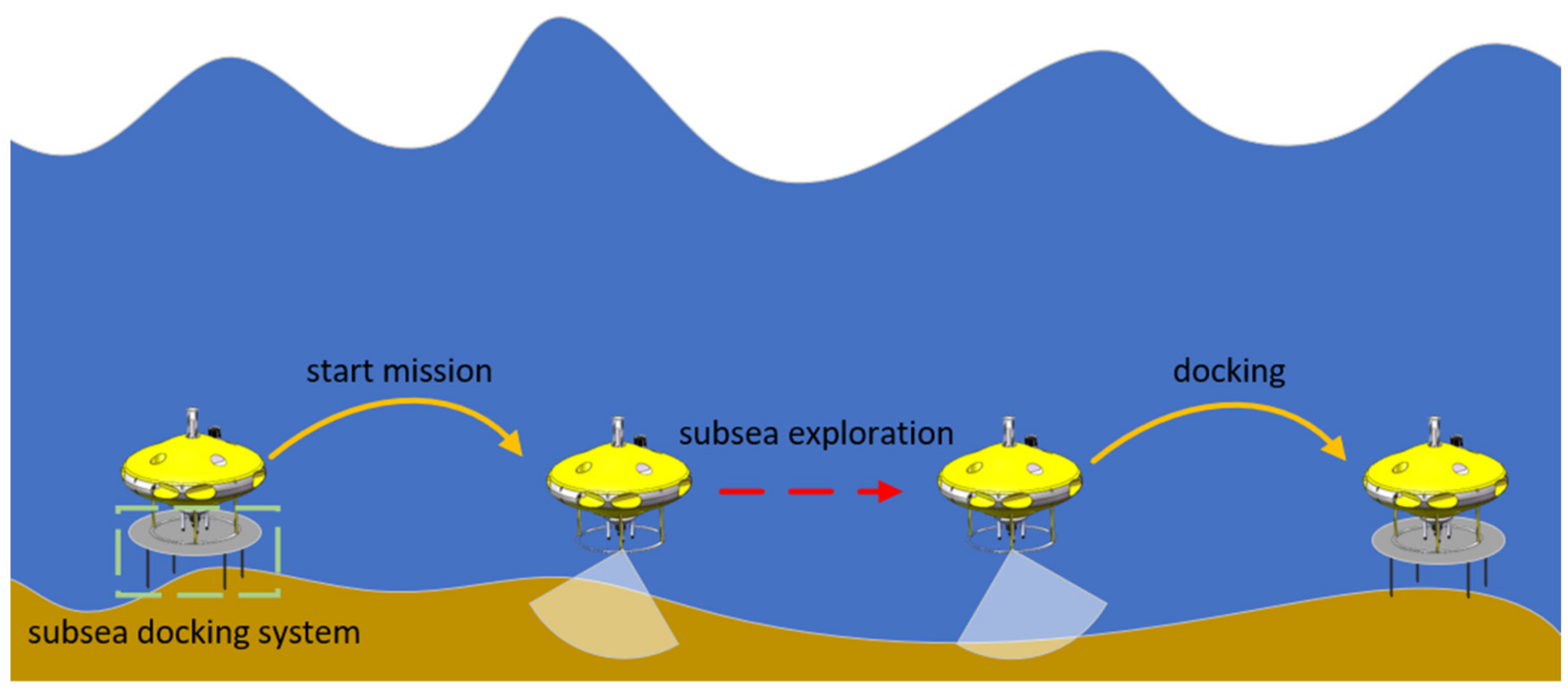
Figure 1. Work pattern of AUH.
Applsci 13 03836 g001
Figure 2. Pitch variation of the AUH at 0.2 m/s.
Applsci 13 03836 g002
Figure 3. Propellers layout.
Applsci 13 03836 g003
Figure 4. Control software and hardware structures of the AUH.
Applsci 13 03836 g004
Figure 5. Coordinate system of AUH.
Applsci 13 03836 g005
Figure 6. Block diagram of LADRC-TD.
Applsci 13 03836 g006
Figure 7. Control flow of the AUH.
Applsci 13 03836 g007
Figure 8. Simulations of heading control with PID, LADRC, and LADRC-TD; (a) heading tracking with the sinusoidal signal; (b) long-span-step response; (c) multi-step response.
Applsci 13 03836 g008aApplsci 13 03836 g008b
Figure 9. Simulations of depth control with PID, LADRC, and LADRC-TD. (a) Long-span-step response; (b) multi-step response.
Applsci 13 03836 g009aApplsci 13 03836 g009b
Figure 10. The pool experiment of the AUH.
Applsci 13 03836 g010
Figure 11. Fixed-point experiment; (a) step response in heading control; (b) step response in the depth control.
Applsci 13 03836 g011
Figure 12. Dynamic experiment: (a) heading tracking with LADRC-TD; (b) heading tracking with PID; (c) trajectory when using LADRC-TD in heading control; (d) trajectory when using PID in heading control; (e) heading tracking error of PID and LADRC-TD in dynamic experiment; (f) depth-keeping with LADRC-TD during AUH proceeding.
Applsci 13 03836 g012
Table 1. The physical parameters and components of Z-AUH.
MassAbout 800 kg
Diameter2 m
Net buoyancy70 N
Propeller layoutFour propellers on the horizon, and two propellers on the vertical, as shown in Figure 3
Maximum Thrust200 N per propeller
ComponentInertial measurement unit (IMU), depth altimeter, sonar, radio, Iridium, Beidou navigation system, buoyancy adjustment, optical camera, ultra-short baseline (USBL)
Table 2. Result summary of each algorithm.
Depth ControlPIDLADRCLADRC-TD
Overshoot43 cm41 cm20 cm
Anti-interferenceworsebaselinenearly
Steady-state error±1.1 m±21 cm±21 cm
Heading ControlPIDLADRCLADRC-TD
Overshoot12°
Anti-interferenceworsebaselinenearly
Steady-state error±3°±2.5°±2.5°
Disclaimer/Publisher’s Note: The statements, opinions and data contained in all publications are solely those of the individual author(s) and contributor(s) and not of MDPI and/or the editor(s). MDPI and/or the editor(s) disclaim responsibility for any injury to people or property resulting from any ideas, methods, instructions or products referred to in the content.