
Elaboration of a Multi-Objective Optimization Method for High-Speed Train Floors Using Composite Sandwich Structures


Abstract
:1. Introduction
- Material selection: In this study, different types of aluminum (Al) honeycomb cores are used in combination with different combinations of Fiber Metal Laminates (FMLs) as face sheets. This particular combination of materials and structural components had not been investigated in the literature before.
- Cost and weight optimization: The elaborated optimization procedure in this study focuses on weight and cost, since only a limited number of previous studies have investigated the relationship between weight and cost reduction simultaneously.
- Flexible design: A wide range of design variables is used in our study to investigate a larger number of feasible designs and determine the optimal sandwich construction.
- Structural integrity: The optimization method used in this study effectively satisfies the specified constraints on the strength of the sandwich structure and the behavior of the final sandwich structure.
- New optimization algorithm: The application of the NCGA algorithm for the structural optimization of floors for high-speed trains represents a new contribution that is not represented in the literature. This highlights the ability of the NCGA algorithm to achieve optimal designs that balance weight reduction and cost efficiency.
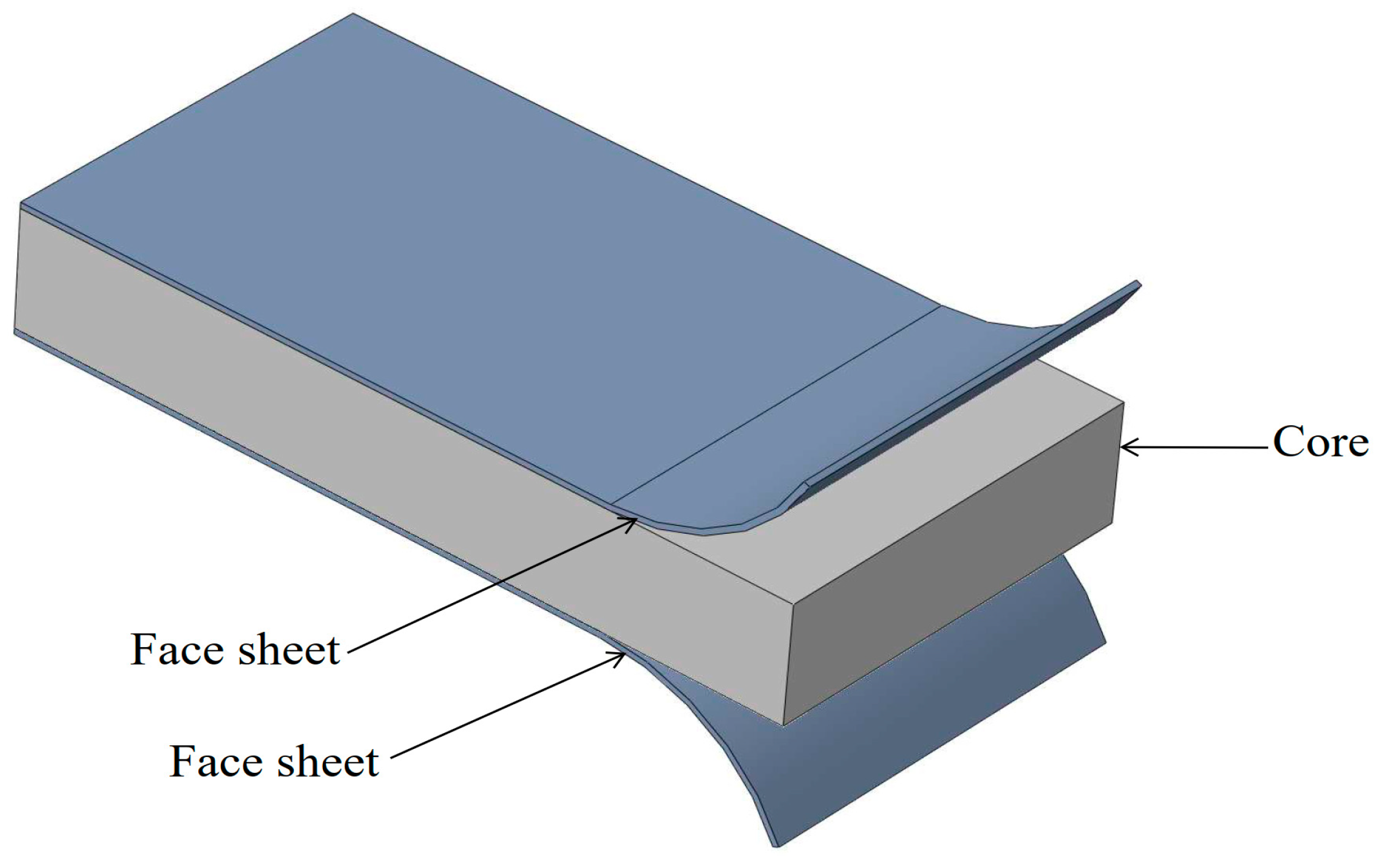
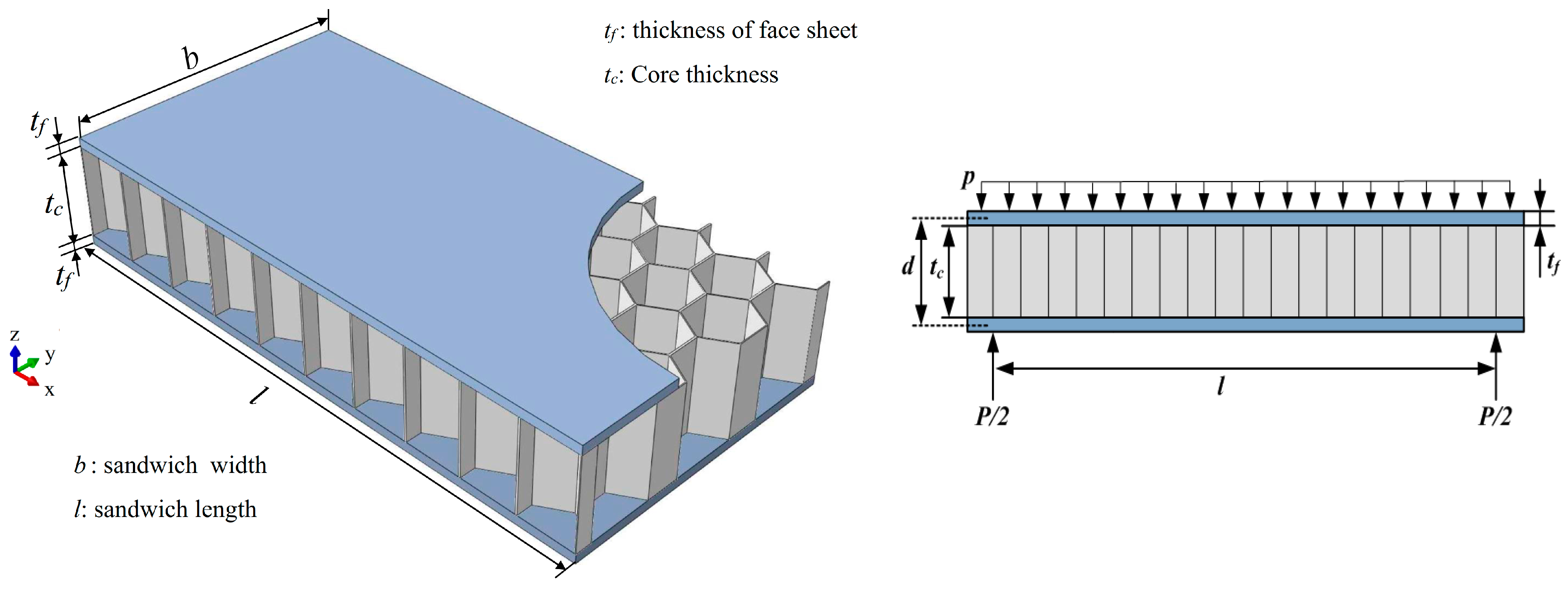
2. Description of the Investigated Train Floor
3. Materials of the Sandwich Structure’s Components
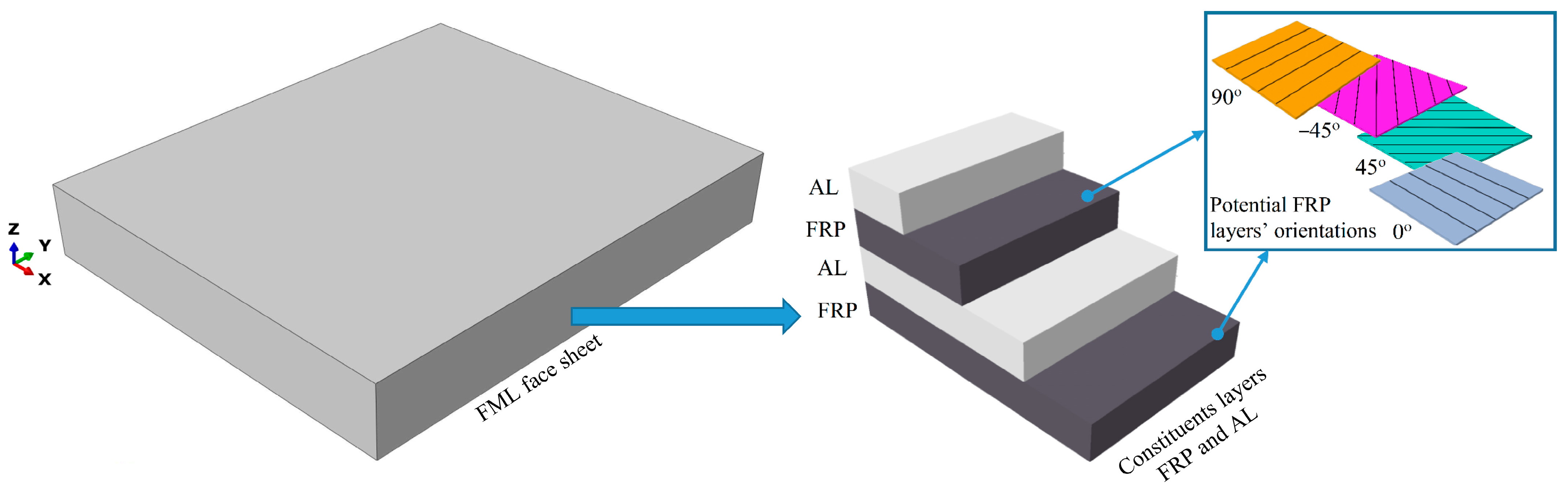
3.1. Materials of the Face Sheets
3.2. Material of the Honeycomb Core
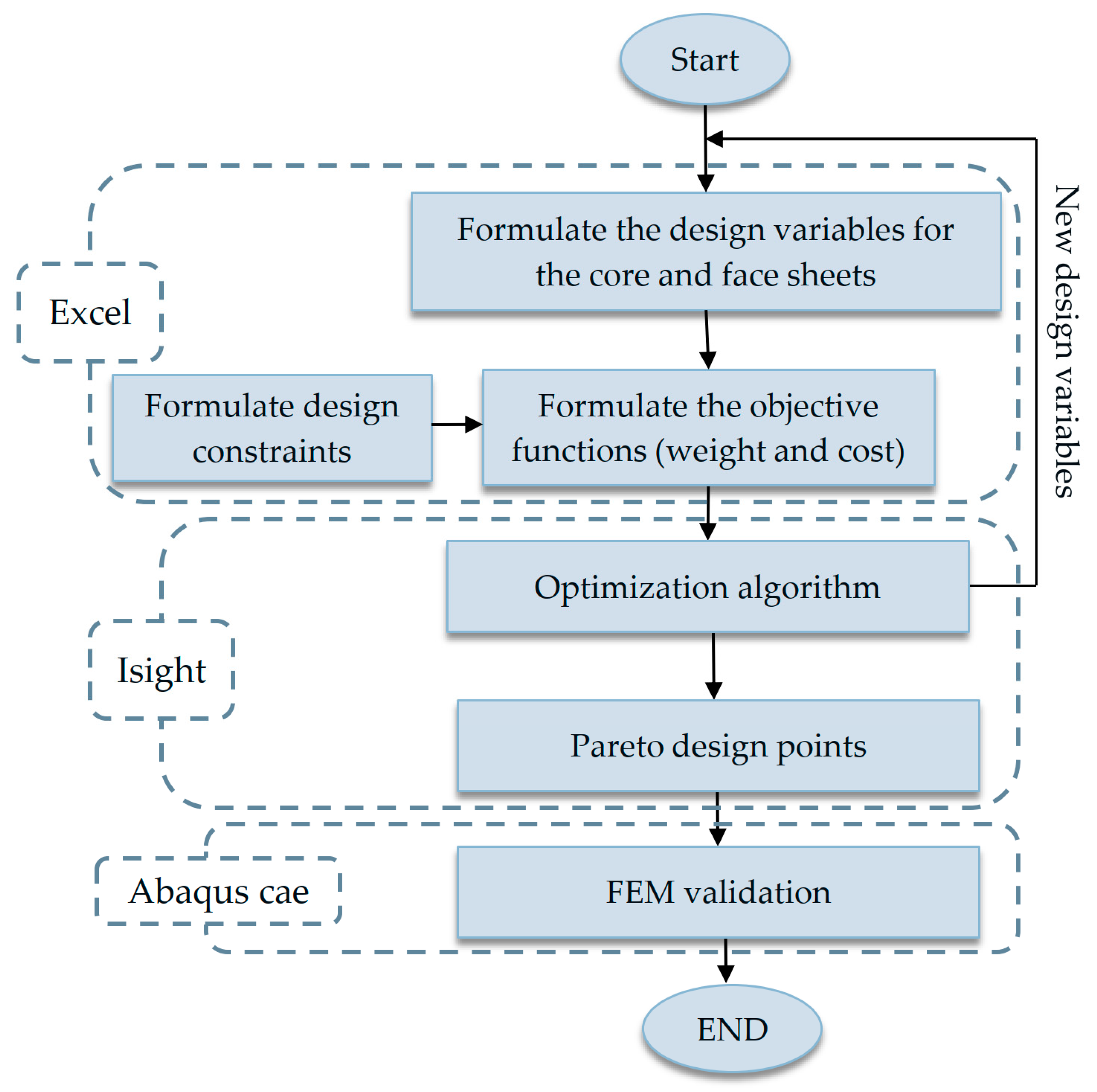
4. Elaboration of the Optimization Method
4.1. Weight and Cost Objective Functions
4.1.1. Weight Objective Function
4.1.2. Cost Objective Function
4.2. Design Variables
4.3. Design Constraints
4.3.1. Constraint for Core Shear
4.3.2. Constraint for Yield Stress in the Face Sheet
4.3.3. Constraint for Face Wrinkling
4.3.4. Constraint for Total Thickness of the Sandwich Structure
4.3.5. Constraint for Total Defection of the Sandwich Structure
5. Numerical Modelling of the Investigated Structure
6. Results of the Optimization and the Finite Element Modeling
6.1. Results of the Elaborated Optimization Method
6.2. Results of the Finite Element Modeling
6.3. Comparison of the Optimization Results and the FE Simulation Outcomes
7. Conclusions
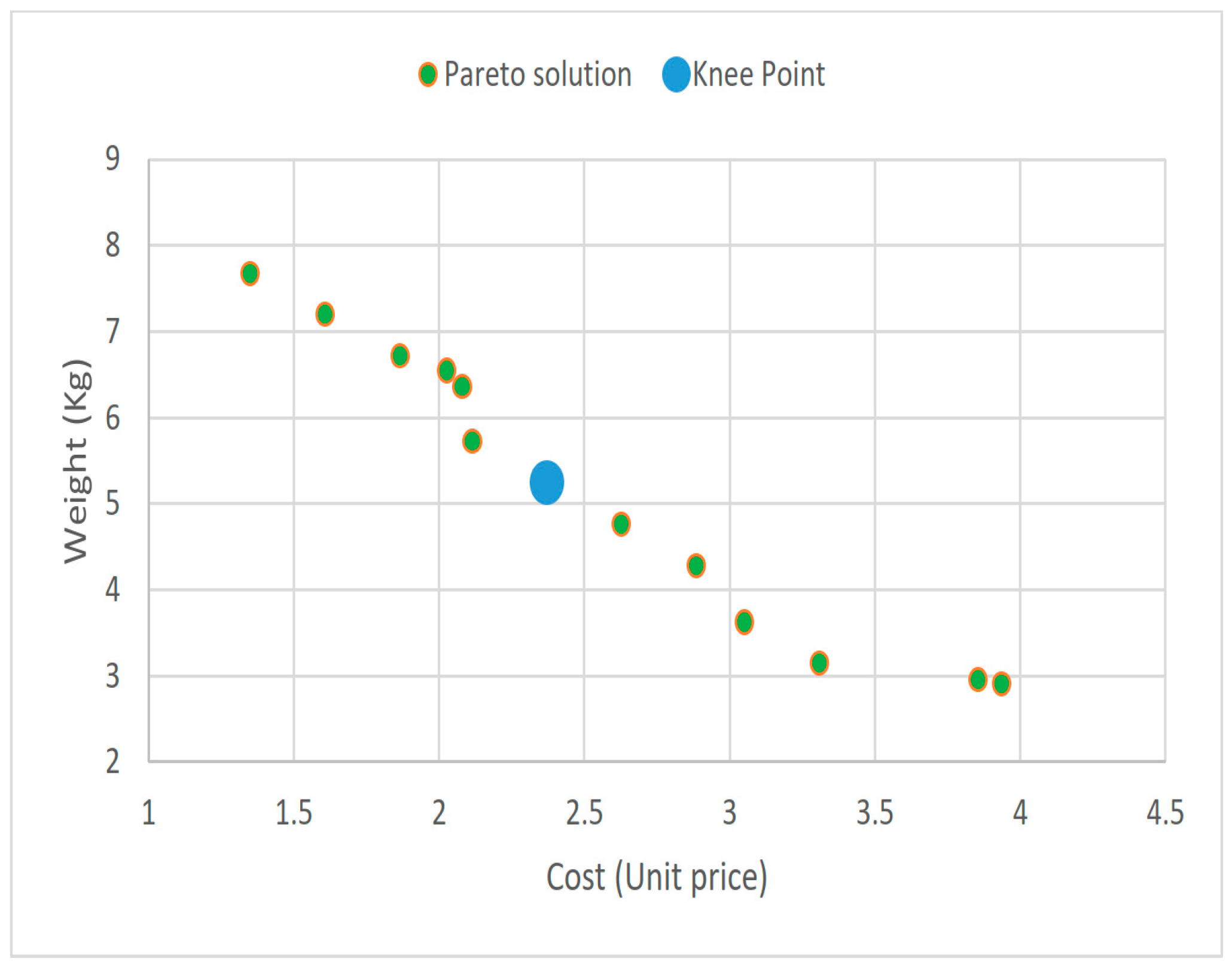
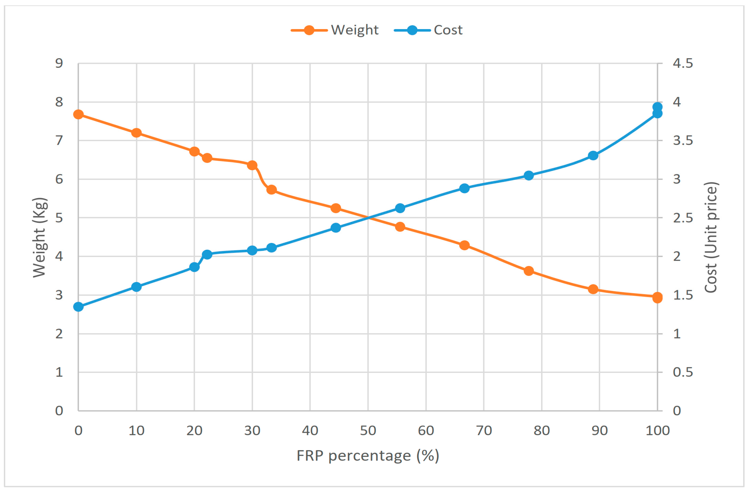
- The analysis showed that, at the expense of cost, using CFRP as a face sheet provided a maximum weight reduction of about 62% in this study, compared to the aluminum face sheet as a basic structure.
- Furthermore, a knee point was identified that strikes a balance between weight and cost, resulting in a weight reduction of approximately 32% by using FML materials. This provides valuable insights for designers who must consider both weight savings and cost-effectiveness when designing high-speed train floors.
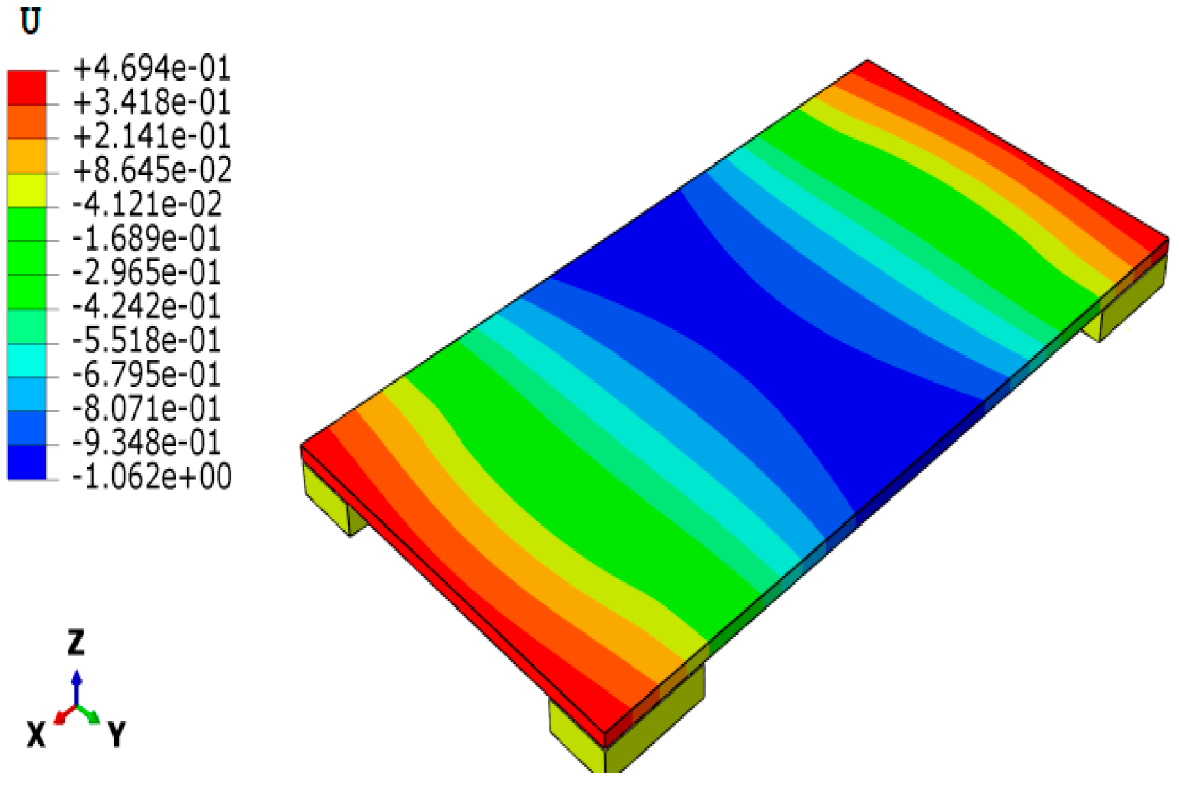
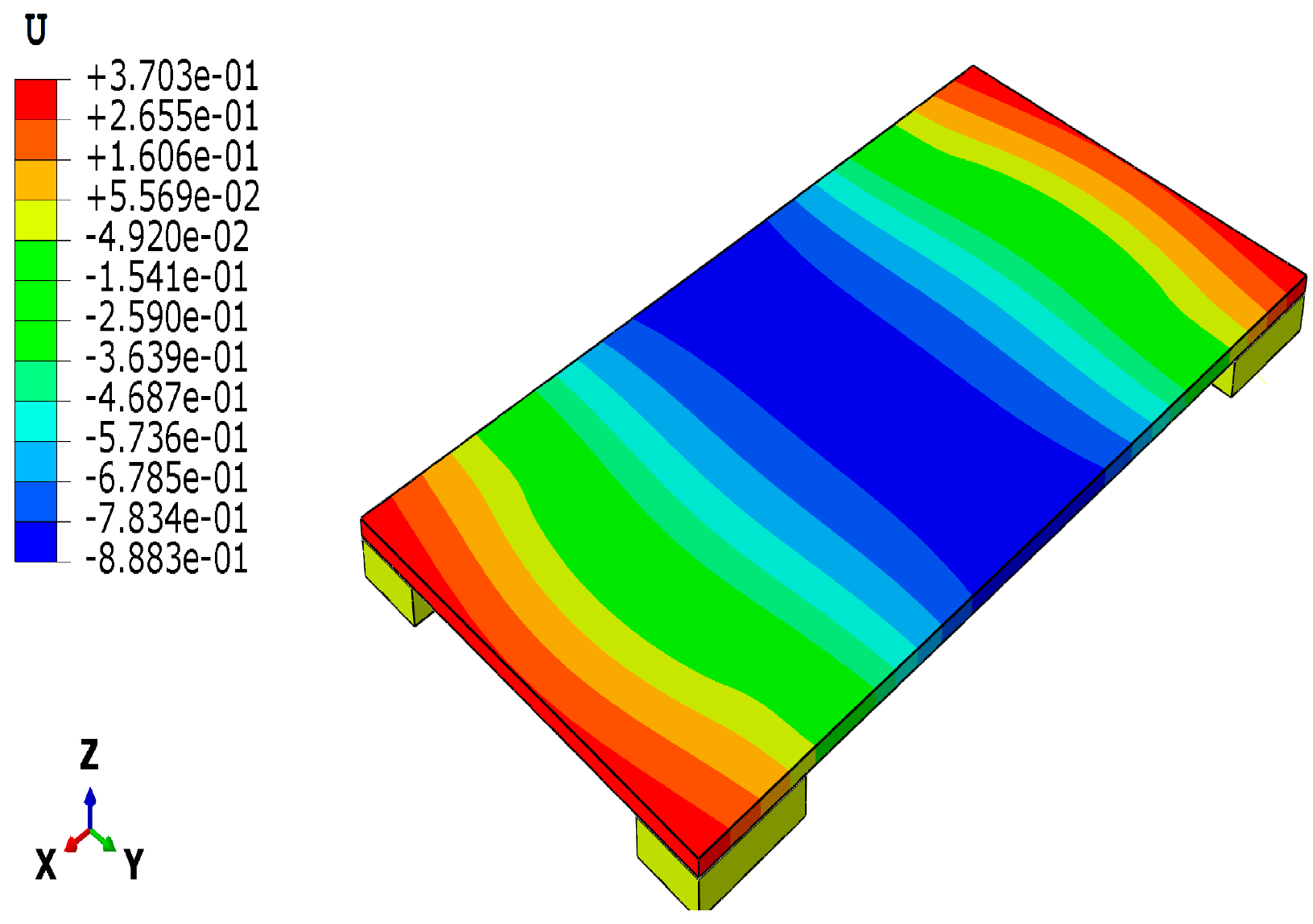
- The present study conducted an optimization process and subsequently validated its outcomes through Finite Element (FE) simulations. The results of the analysis indicated that there was an acceptable level of agreement between the optimization process and the FE simulations with a maximum difference value of about 11%. This provides a reasonable level of confidence in the obtained results.
Author Contributions
Funding
Institutional Review Board Statement
Informed Consent Statement
Data Availability Statement
Acknowledgments
Conflicts of Interest
References
- Qi, D.; Sun, Q.; Zhang, S.; Wang, Y.; Zhou, X. Buckling analysis of a composite honeycomb reinforced sandwich embedded with viscoelastic damping material. Appl. Sci. 2022, 12, 10366. [Google Scholar] [CrossRef]
- Jin, X.S. Key problems faced in high-speed train operation. J. Zhejiang Univ. Sci. A 2014, 15, 936–945. [Google Scholar] [CrossRef] [Green Version]
- Zhang, J.; Xiao, X.; Sheng, X.; Zhang, C.; Wang, R.; Jin, X. SEA and contribution analysis for interior noise of a high speed train. Appl. Acoust. 2016, 112, 158–170. [Google Scholar] [CrossRef]
- Mistry, P.J.; Johnson, M.S.; McRobie, C.A.; Jones, I.A. Design of a lightweight multifunctional composite railway axle utilising coaxial skins. J. Compos. Sci. 2021, 5, 77. [Google Scholar] [CrossRef]
- Virág, Z.; Jármai, K. Optimum design of stiffened plates for static or dynamic loadings using different ribs. Struct. Eng. Mech. 2020, 74, 255–266. [Google Scholar]
- Khosravani, M.R.; Weinberg, K. Characterization of sandwich composite T-joints under different ageing conditions. Compos. Struct. 2018, 197, 80–88. [Google Scholar] [CrossRef]
- Feng, Y.; Qiu, H.; Gao, Y.; Zheng, H.; Tan, J. Creative design for sandwich structures: A review. Int. J. Adv. Robot. Syst. 2020, 17, 1729881420921327. [Google Scholar] [CrossRef]
- SBrückmann, M.; Friedrich, H.E.; Kriescher, M.; Kopp, G.; Gätzi, R. Lightweight sandwich structures in innovative vehicle design under crash load cases. Mater. Sci. Forum 2017, 879, 2419–2427. [Google Scholar] [CrossRef]
- Hagnell, M.K.; Kumaraswamy, S.; Nyman, T.; Åkermo, M. From aviation to automotive—A study on material selection and its implication on cost and weight efficient structural composite and sandwich designs. Heliyon 2020, 6, e03716. [Google Scholar] [CrossRef] [PubMed]
- Sayyad, A.S.; Ghugal, Y.M. Bending, buckling and free vibration of laminated composite and sandwich beams: A critical review of literature. Compos. Struct. 2017, 171, 486–504. [Google Scholar] [CrossRef]
- Liu, Q.; Fu, J.; Wang, J.; Ma, J.; Chen, H.; Li, Q. Hui, Axial and lateral crushing responses of aluminum honeycombs filled with EPP foam. Compos. Part B Eng. 2017, 130, 236–247. [Google Scholar] [CrossRef]
- Kwon, D.J.; Kim, J.H.; Devries, K.L.; Park, J.M. Optimized epoxy foam interface of CFRP/Epoxy Foam/CFRP sandwich composites for improving compressive and impact properties. J. Mater. Res. Technol. 2021, 11, 62–71. [Google Scholar] [CrossRef]
- Sahib, M.M.; Kovács, G.; Szávai, S. Optimum Design for the Bottom Panel of a Heavy-Duty Truck by Using a Composite Sandwich Structure. In Vehicle and Automotive Engineering 4: Select Proceedings of the 4th VAE2022, Miskolc, Hungary; Springer: Cham, Switzerland, 2022; pp. 734–746. [Google Scholar]
- Seyyedrahmani, F.; Shahabad, P.K.; Serhat, G.; Bediz, B.; Basdogan, I. Multi-objective optimization of composite sandwich panels using lamination parameters and spectral Chebyshev method. Compos. Struct. 2022, 289, 115417. [Google Scholar] [CrossRef]
- Manalo, A.; Aravinthan, T. Behavior of Full-Scale Railway Turnout Sleepers from Glue-Laminated Fiber Composite Sandwich Structures. J. Compos. Constr. 2012, 16, 724–736. [Google Scholar] [CrossRef]
- Cho, J.G.; Koo, J.S.; Jung, H.S. A lightweight design approach for an EMU carbody using a material selection method and size optimization. J. Mech. Sci. Technol. 2016, 30, 673–681. [Google Scholar] [CrossRef]
- Zinno, A.; Fusco, E.; Prota, A.; Manfredi, G. Multiscale approach for the design of composite sandwich structures for train application. Compos. Struct. 2010, 92, 2208–2219. [Google Scholar] [CrossRef]
- Heller, P.; Korinek, J.; Triska, L. Hybrid body of underground railway car: Path towards reduced weight of rail vehicles. Mod. Mach. Sci. J. 2015, 2015, 631–634. [Google Scholar] [CrossRef]
- Yao, D.; Zhang, J.; Wang, R.Q.; Xiao, X.B.; Guo, J.Q. Lightweight design and sound insulation characteristic optimisation of railway floating floor structures. Appl. Acoust. 2019, 156, 66–77. [Google Scholar] [CrossRef]
- Wennberg, D.; Stichel, S. Multi-functional design of a composite high-speed train body structure. Struct. Multidiscip. Optim. 2014, 50, 475–488. [Google Scholar] [CrossRef]
- Mozafari, H.; Khatami, S.; Molatefi, H. Out of plane crushing and local stiffness determination of proposed foam filled sandwich panel for Korean Tilting Train eXpress—Numerical study. Mater. Des. 2015, 66, 400–411. [Google Scholar] [CrossRef]
- Zhong, L.; Guo, L.; Li, Y.; Wang, C. Local anti-ablation modification of uneven-density C/C composites with the ZrC-SiC composite ceramics. Mater. Charact. 2023, 198, 112722. [Google Scholar] [CrossRef]
- De Cicco, D.D.; Taheri, F. Delamination buckling and crack propagation simulations in fiber-metal laminates using xFEM and cohesive elements. Appl. Sci. 2018, 8, 2440. [Google Scholar] [CrossRef] [Green Version]
- Gao, S.; Hou, W.; Xing, J.; Sang, L. Numerical and experimental investigation of flexural properties and damage behavior of CFRTP/Al laminates with different stacking sequence. Appl. Sci. 2023, 13, 1667. [Google Scholar] [CrossRef]
- Vieira, L.M.G.; Dobah, Y.; Santos, J.C.D.; Panzera, T.H.; Rubio, J.C.C.; Scarpa, F. Impact properties of novel natural fibre metal laminated composite materials. Appl. Sci. 2022, 12, 1869. [Google Scholar] [CrossRef]
- Chang, H.; Zhang, L.; Dou, W.; Zhang, H. Improved strategies for the load-bearing capacity of aluminum-PVC foam sandwich floors of a high-speed train. J. Mech. Sci. Technol. 2021, 35, 651–659. [Google Scholar] [CrossRef]
- Nestler, D.; Trautmann, M.; Zopp, C.; Tröltzsch, J.; Osiecki, T.; Nendel, S.; Wagner, G.; Kroll, L. Continuous film stacking and thermoforming process for hybrid CFRP/aluminum laminates. Procedia CIRP 2017, 66, 107–112. [Google Scholar] [CrossRef]
- Baumert, E.K.; Johnson, W.S.; Cano, R.J.; Jensen, B.J.; Weiser, E.S. Mechanical evaluation of new fiber metal laminates made by the VARTM process. In Proceedings of the 17th International Conference on Composite Materials (ICCM), Edinburgh, UK, 27–31 July 2009. [Google Scholar]
- HexCel Composites, Honeycomb Sandwich Design Technology. 2000. Available online: https://www.hexcel.com/user_area/content_media/raw/Honeycomb_Sandwich_Design_Technology.pdf (accessed on 20 February 2023).
- Watanabe, S.; Hiroyasu, T.; Miki, M. NCGA: Neighborhood cultivation genetic algorithm for multi-objective optimization problems. Proc. Genet. Evol. Comput. Conf. 2002, 43, 465–468. [Google Scholar]
- Chen, Y.; Fu, K.; Hou, S.; Han, X.; Ye, L. Multi-objective optimization for designing a composite sandwich structure under normal and 45° impact loadings. Compos. Part B Eng. 2018, 142, 159–170. [Google Scholar] [CrossRef]
- Duan, S.; Tao, Y.; Han, X.; Yang, X.; Hou, S.; Hu, Z. Investigation on structure optimization of crashworthiness of fiber reinforced polymers materials. Compos. Part B Eng. 2014, 60, 471–478. [Google Scholar] [CrossRef]
- Chen, Y.; Liu, G.; Zhang, Z.; Hou, S. Integrated design technique for materials and structures of vehicle body under crash safety considerations. Struct. Multidiscip. Optim. 2017, 56, 455–472. [Google Scholar] [CrossRef]
- Zenkert, D. An Introduction to Sandwich Construction; Engineering Materials Advisory Services (EMAS): London, UK; Stockholm, Sweden, 1995. [Google Scholar]
- Kollar, L.P.; Springer, G.S. Mechanics of Composite Structures, 1st ed.; Cambridge University Press: Cambridge, UK, 2003. [Google Scholar]
- Kaw, A.K. Mechanics of Composite Materials; Taylor & Francis: New York, NY, USA, 2005. [Google Scholar]
- Hudson, C.W.; Carruthers, J.J.; Robinson, A.M. Multiple objective optimisation of composite sandwich structures for rail vehicle floor panels. Compos. Struct. 2010, 92, 2077–2082. [Google Scholar] [CrossRef]
- Barbero, E.J. Finite Element Analysis of Composite Materials Using AbaqusTM, 2nd ed.; Taylor & Francis: New York, NY, USA, 2013. [Google Scholar]
- Yuan, J.; Zhang, L.; Huo, Z. An equivalent modeling method for honeycomb sandwich structure based on orthogonal anisotropic solid element. Int. J. Aeronaut. Space Sci. 2020, 21, 957–969. [Google Scholar] [CrossRef]


| Material Properties | CFRP | GFRP | AL |
|---|---|---|---|
| Longitudinal modulus: Ex [MPa] | 130,000 | 43,000 | 70,000 |
| Transverse modulus: Ey [MPa] | 10,000 | 8000 | 70,000 |
| In-plane shear modulus: Gxy [MPa] | 5000 | 4300 | 26,000 |
| Major Poisson’s ratio: νxy [-] | 0.28 | 0.25 | 0.33 |
| Density: ρf [kg/m3] | 1600 | 1800 | 2780 |
| Lamina thickness: tl [mm] | 0.125 | 0.125 | 0.2 |
| Longitudinal tensile strength: σxt [MPa] | 2000 | 1140 | 186 |
| Longitudinal compressive strength: σxc [MPa] | 1300 | 620 | 186 |
| Transverse tensile strength: σyt [MPa] | 78 | 39 | 186 |
| Transverse compressive strength: σyc [MPa] | 246 | 128 | 186 |
| In-plane shear strength: σxy [MPa] | 68 | 60 | 110 |
| Density | Properties in x Direction | Properties in y Direction | Properties in z Direction | |||
|---|---|---|---|---|---|---|
| ρc [kg/m3] | Strength: σxz [MPa] | Modulus: Gxz [MPa] | Strength: σyz [MPa] | Modulus: Gyz [MPa] | Strength: σzz [MPa] | Modulus: Ezz [MPa] |
| 29 | 0.4 | 55 | 0.65 | 110 | 0.9 | 165 |
| 37 | 0.45 | 90 | 0.8 | 190 | 1.4 | 240 |
| 42 | 0.5 | 100 | 0.9 | 220 | 1.5 | 275 |
| 54 | 0.85 | 130 | 1.4 | 260 | 2.5 | 540 |
| 59 | 0.9 | 140 | 1.45 | 280 | 2.6 | 630 |
| 83 | 1.5 | 220 | 2.4 | 440 | 4.6 | 1000 |
| 29 | 0.4 | 55 | 0.65 | 110 | 0.9 | 165 |
| 37 | 0.45 | 90 | 0.8 | 190 | 1.4 | 240 |
| 42 | 0.5 | 100 | 0.9 | 220 | 1.5 | 275 |
| 54 | 0.85 | 130 | 1.4 | 260 | 2.5 | 540 |
| Steps | Process Description |
|---|---|
| Step 1. | Initialization—In this step, an initial population P0 of size N is established, and the generation is set to an initial value of g = 0. The fitness values associated with individuals in P0 are calculated, and P0 is copied into an archive A0 of size N. |
| Step 2. | Generation—A new generation is created by incrementing the generation counter (g = g + 1) and selecting the parent population (Pg) from the previous archive (Ag−1). |
| Step 3. | Sorting—The population is sorted based on the specified objectives for the current generation. If optimizing for two objective functions, the first objective is chosen in the first generation, the second objective in the second generation, and so on. |
| Step 4. | Grouping—Pg is split into two groups consisting of stored individuals. |
| Step 5. | Crossover and Mutation—Crossover and mutation operations are performed on each group, producing two child individuals from two parent groups and then eliminating the parent groups. |
| Step 6. | Assembly—The child groups generated in Step 5 are assembled to produce a new population (Pg). |
| Step 7. | Archive Renewal—Pg and Ag-1 are combined to generate 2N individuals. Environment selection is then conducted to reduce the number of individuals to N, and a new archive (Ag) is generated. |
| Step 8. | Termination—The terminal criterion is verified. If the criterion has been met, the process can be stopped. If not, the algorithm returns to Step 2. |
| Design Variables | Value | Remark |
|---|---|---|
| Number of face sheet layers | Discrete variable, Integer values | |
| Face sheet materials | CFRP layer: identified by No. 1 GFRP layer: identified by No. 2 Aluminum layer: identified by No. 3 | Discrete variable, Integer values |
| possible FRP composite layup orientation | Discrete variable | |
| Core density | Discrete as specified in the Table 2 | |
| Core thickness | [mm] | Continuous value |
| Face Sheet Materials and Fiber Orientations | No. of Layers | Core Thickness tc | Face Sheet Thickness tf | Core Density ρc | Cost Ct | Weight Wt |
|---|---|---|---|---|---|---|
| CFRP layer: identified by No. 1 GFRP layer: identified by No. 2 Aluminum layer: identified by No. 3 | (mm) | (mm) | (kg/m3) | (unit price) | (kg) | |
| 1(0°), 1(0°), 1(0°), 1(0°), 1(0°), 1(0°), 1(0°), 1(0°), 1(0°), 1(0°) | 10 | 18.2 | 1.25 | 37 | 3.93 | 2.92 |
| 1(0°), 2(0°), 1(0°), 1(0°), 1(0°), 1(0°), 1(0°), 1(0°), 1(0°), 1(0°) | 10 | 18.02 | 1.25 | 37 | 3.85 | 2.96 |
| 1(0°), 3, 1(0°), 1(0°), 1(0°), 1(0°), 1(0°), 1(0°), 1(0°) | 9 | 18.47 | 1.2 | 37 | 3.31 | 3.15 |
| 1(0°), 3, 1(0°), 1(0°), 1(0°), 1(0°), 1(0°), 3, 1(0°) | 9 | 18.47 | 1.275 | 37 | 3.05 | 3.63 |
| 1(0°), 3, 1(0°), 1(0°), 1(0°), 3, 3, 1(0°), 1(0°) | 9 | 17.88 | 1.35 | 54 | 2.88 | 4.29 |
| 3, 3, 1(0°), 1(0°), 1(0°), 1(0°), 3, 1(0°), 3 | 9 | 17.97 | 1.425 | 54 | 2.63 | 4.77 |
| 3, 3, 1(0°), 1(0°), 1(0°), 3, 3, 1(0°), 3 | 9 | 18.04 | 1.5 | 54 | 2.37 | 5.25 |
| 3, 3, 1(0°), 3, 1(0°), 3, 3, 1(0°), 3 | 9 | 18.13 | 1.575 | 54 | 2.11 | 5.73 |
| 3, 3, 3, 1(0°), 3, 3, 3, 1(0°), 3, 2(0°) | 10 | 18.2 | 1.775 | 42 | 2.08 | 6.36 |
| 3, 3, 3, 3, 1(0°), 3, 3, 1(0°), 3 | 9 | 18.13 | 1.65 | 83 | 2.03 | 6.55 |
| 3, 3, 3, 1(0°), 3, 3, 3, 1(0°), 3, 3 | 10 | 17.8 | 1.85 | 37 | 1.86 | 6.72 |
| 3, 3, 3, 3, 3, 3, 3, 3, 3, 1(0°) | 10 | 17.93 | 1.925 | 37 | 1.61 | 7.2 |
| 3, 3, 3, 3, 3, 3, 3, 3, 3, 3 | 10 | 17.94 | 2 | 37 | 1.35 | 7.68 |
| Face Sheet Layup | Face Sheet Materials and Fiber Orientations | No. of Layers | Core Thickness tc | Face Sheet Thickness tf | Core Density ρc | Values of the Objectives |
|---|---|---|---|---|---|---|
| CFRP layer: No. 1 GFRP layer: No. 2 Aluminum layer: No. 3 | (mm) | (mm) | (kg/m3) | |||
| Totally FRP | 1(0°), 1(0°), 1(0°), 1(0°), 1(0°), 1(0°), 1(0°), 1(0°), 1(0°), 1(0°) | 10 | 18.2 | 1.25 | 37 | Minimal weight Wt = 2.92 kg Ct = 3.93 unit price |
| Totally Al | 3, 3, 3, 3, 3, 3, 3, 3, 3, 3 | 10 | 17.94 | 2 | 37 | Minimal cost Wt = 7.68 kg Ct = 1.35 unit price |
| FML | 3, 3, 1(0°), 1(0°), 1(0°), 3, 3, 1(0°), 3 | 9 | 18.04 | 1.5 | 54 | Knee point Wt =5.25 kg Ct = 2.37 unit price |
| Design Points | Maximal Deflection (mm) | Maximal Stress in the Face Sheet (MPa) | Remarks | ||||
|---|---|---|---|---|---|---|---|
| Optimization Result | FEM Result | Difference (%) | Optimization Result | FEM Result | Difference (%) | ||
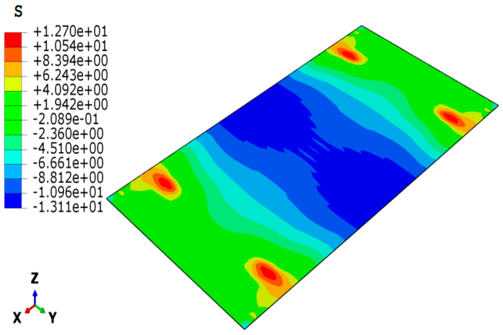
| Minimal weight | 0.9957 | 1.004 | 0.83 | 13.655 | 13.11 | 3.99 | single weight optimization |
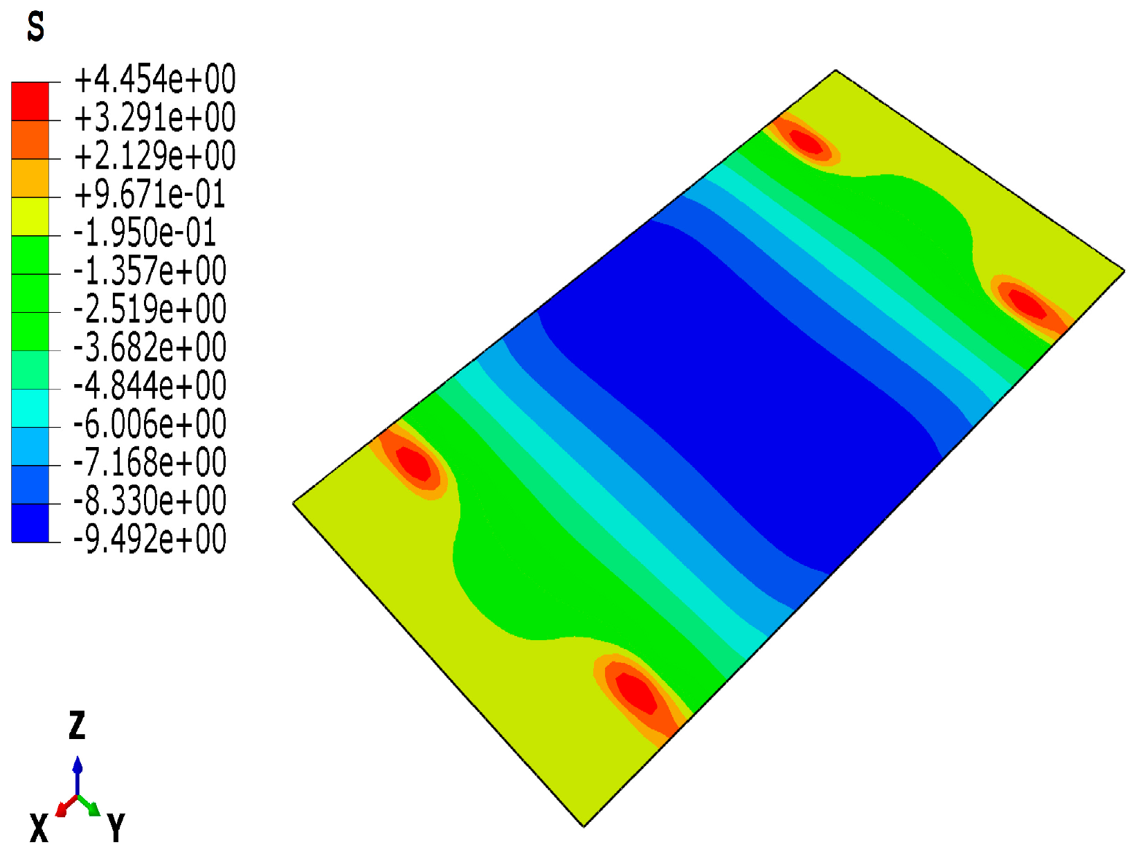
| Minimal cost | 1 | 1.062 | 6.20 | 8.695 | 9.49 | 9.14 | single cost optimization |
| Knee point | 0.9999 | 0.883 | 11.69 | 11.3333 | 10.26 | 9.47 | multi-objective weight and cost optimization |
Disclaimer/Publisher’s Note: The statements, opinions and data contained in all publications are solely those of the individual author(s) and contributor(s) and not of MDPI and/or the editor(s). MDPI and/or the editor(s) disclaim responsibility for any injury to people or property resulting from any ideas, methods, instructions or products referred to in the content. |
© 2023 by the authors. Licensee MDPI, Basel, Switzerland. This article is an open access article distributed under the terms and conditions of the Creative Commons Attribution (CC BY) license (https://creativecommons.org/licenses/by/4.0/).
Share and Cite
Sahib, M.M.; Kovács, G. Elaboration of a Multi-Objective Optimization Method for High-Speed Train Floors Using Composite Sandwich Structures. Appl. Sci. 2023, 13, 3876. https://doi.org/10.3390/app13063876
Sahib MM, Kovács G. Elaboration of a Multi-Objective Optimization Method for High-Speed Train Floors Using Composite Sandwich Structures. Applied Sciences. 2023; 13(6):3876. https://doi.org/10.3390/app13063876
Chicago/Turabian StyleSahib, Mortda Mohammed, and György Kovács. 2023. "Elaboration of a Multi-Objective Optimization Method for High-Speed Train Floors Using Composite Sandwich Structures" Applied Sciences 13, no. 6: 3876. https://doi.org/10.3390/app13063876