1. Introduction
The transmission of 3D holographic video content along conventional communication channels requires substantial compression of the holographic information, as demonstrated in [
1,
2,
3,
4,
5]. It is shown in [
6], through the analysis of the modern situation in this area, that the traditional methods of entropy coding are currently far from being able to implement a 10
6-fold compression of the holographic information, which is necessary for transmission. For this reason, an algorithm was proposed that provides the transmission of 3D holographic information in the form of two basic modalities of a 3D image, namely, the surface texture of the holographic object (the 3D scene) and its topographic depth map [
7], which allows the necessary compression of the holographic information and its transmission similar to the transmission of a radio signal by means of single-sideband modulation (SSB). One of the methods of depth mapping is the technology of structured light lateral projection [
8,
9,
10,
11,
12,
13]. The vertical fringes of structured light form a pattern of spatial bands similar to a spatial frequency carrier hologram, and their deformation is similar to deviations containing the information on the 3D object. Light diffraction from a structure of this kind forms several orders so that one of these orders restores the image of the 3D depth map. The numerical superposition of the texture of the holographic object onto this map leads to the creation of an image of the 3D object. Another possible version of the restoration of a 3D image is in texture superposition directly on the structured light pattern in the form of vertical fringes. Diffraction on this structure in the minus-first order will restore the 3D image, as this happens in the case of holograms of focused images when the number of Rayleigh zones is much more than ten. This is similar to the restoration of the initial object by a hologram of focused images and simplifies the computer rendering of dynamically changing scenes restoring the 3D holographic video stream, which possesses continuous parallax, both horizontal and vertical, and high spatial resolution, not worse than Full HD and even 4K standard.
2. The Holographic Model
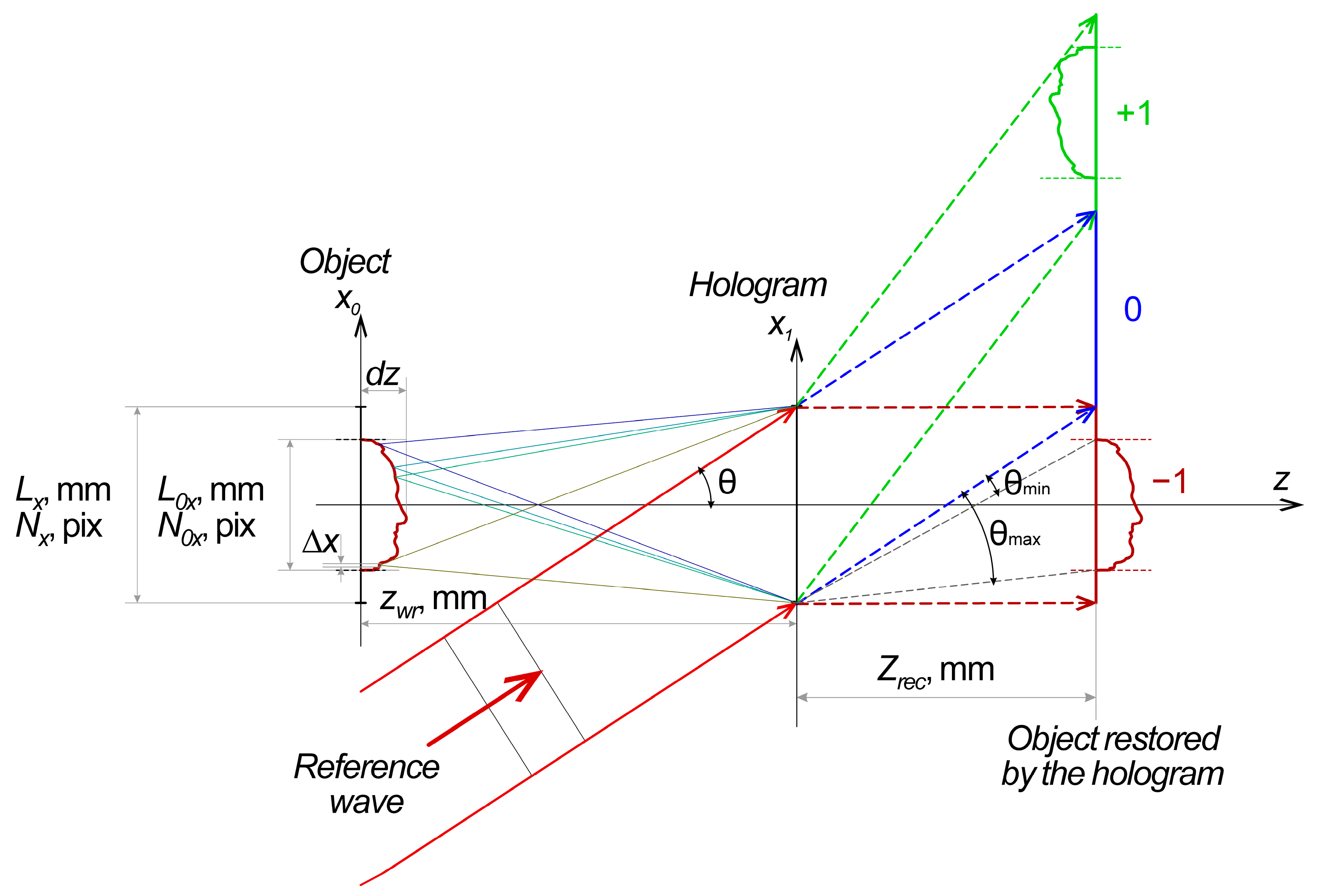
Modeling of the synthesis of the hologram and its corresponding structured light fringe pattern (SLFP) without loss of generality was carried out according to Leith–Upatnieks’ holographic scheme (
Figure 1).
A photo-response proportional to τ(
x1,
y1) is formed in the hologram plane, and it forms the hologram in the case of either phase or amplitude holograms. For digital holograms, this response has the same appearance (1):
where
Io(
x1,
y1) and
Ir(
x1,
y1) are the intensities of the object and reference waves, and φ
o and φ
r are their phases, respectively. The multiplier standing at the cosine is the visibility (
V) of the interference structure of the hologram. The carrier spatial frequency formed in (1) of plane waves that are permanent over the (
x1,
y1) space in the simple case is proportional to the derivative of φ
o with respect to the coordinate, while its deviation, containing the information on the holographic object [
14], is proportional to the derivative of φ
r depending on the wavelength λ, which allows one to separate diffraction orders in the restoration plane (
x1,
y1), while
dx,ymax and
dx,ymin are their deviations.
In the general case, the interference structure of the hologram is more complicated, because both in the carrier spatial frequency and in its deviation, the variable over the coordinates
V(
x1,
y1) makes its own contribution to spatial harmonics, so it is better to study them by means of numerical modeling [
14,
15,
16]. The classical approach to the digital synthesis of a hologram is in the computer modeling of the process according to
Figure 1. Diffraction from this holographic structure forms several orders, one of which restores the 3D image of the holographic object. A comparison between the diffraction of this synthesized hologram and the pattern of the lateral projection of vertical structured-light fringes is presented below.
3. Numerical Experiment
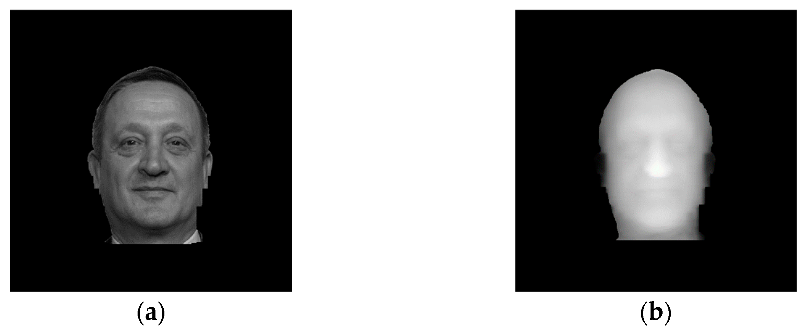
The initial frames used to render 3D images of the holographic object are shown in
Figure 2.
It is necessary to use Fresnel transformation to describe the propagation of monochromatic radiation in the space both for hologram synthesis and for image restoration by the hologram, but this transformation is very resource-intensive, so its analog, based on the fast Fourier transform (FFT) [
17,
18,
19,
20,
21,
22], is usually used. We use it by splitting a 3D holographic object with a depth of
dz (
Figure 1) into
p layers. This allows one to accelerate the calculations but poses an inconvenient limitation: the same pixel resolution of the hologram, the holographed object, and the restored image. In addition, FFT works only with flat objects, with a depth not more than λ, so the treatment of deeper objects involves phase failure when it passes through π. To restore it, a complicated and noise-sensitive phase unwrapping algorithm is to be applied [
23,
24,
25,
26]. For a large number of phase wraps through 2π, the phase unwrapping method does not work well. To avoid this, we applied another algorithm. The holographic object was compressed by a factor of Ҟ in-depth to the size of λ/2, and then, after recording the hologram and restoring the image, again extended to the previous depth. The described operation did not affect the accuracy of depth reproduction because all of the variables are represented in the program in the floating-point format. This operation gives rise to the array of data in which, over the whole frame, the structured fringes shift by less than one fringe, and the phase-wrapping effect disappears. Then, to simplify the calculations without any loss of generality, we will depict the texture in one composite color.
4. The Synthesis of Holograms and Structured Fringe Patterns with the Same Period
To simplify calculation procedures, the consideration will be limited to the case of the holograms of focused images, when the plane (
x0,
y0) with the object of holography (
Figure 1) is transferred to the plane (
x1,
y1), in which it would be necessary to perform Fresnel transformation, not at the stage of hologram synthesis but only later, when obtaining the image restored by the holograms. It is difficult to create material holograms in this way since the material object overlaps the reference beam with its shadow, and computer holograms are quite possible. A hologram with a period of 3 pixels per fringe, synthesized using the above-described method, is shown in
Figure 3.
Similarly, by transforming the depth of the 3D object (
Figure 2d) to the size of λ/2 and increasing the fringe frequency (
Figure 2c) by their median multiplexing to 3 pixels per one fringe, we made the pattern of structured fringes with a period equal to the period of the carrier frequency at the hologram (
Figure 4).
To compare the results of diffraction from structures in
Figure 3 and
Figure 4, Fourier transforms describing Fraunhofer diffraction were calculated, along with Fresnel transformations from each structure. The results for both the Fresnel and Fourier transforms are described below. The results of our further investigation, with the help of both transforms, turned out to be the same. For this reason, we show only the images obtained using the Fresnel transform below because they provide a more obvious illustration of image restoration at the final distance from the hologram and the same distance from the structured light fringe pattern. Both cases, namely the Fourier and Fresnel diffraction, correspond to image restoration according to the scheme shown in
Figure 1 into the zero and plus-minus first diffraction orders for the corresponding hologram types.
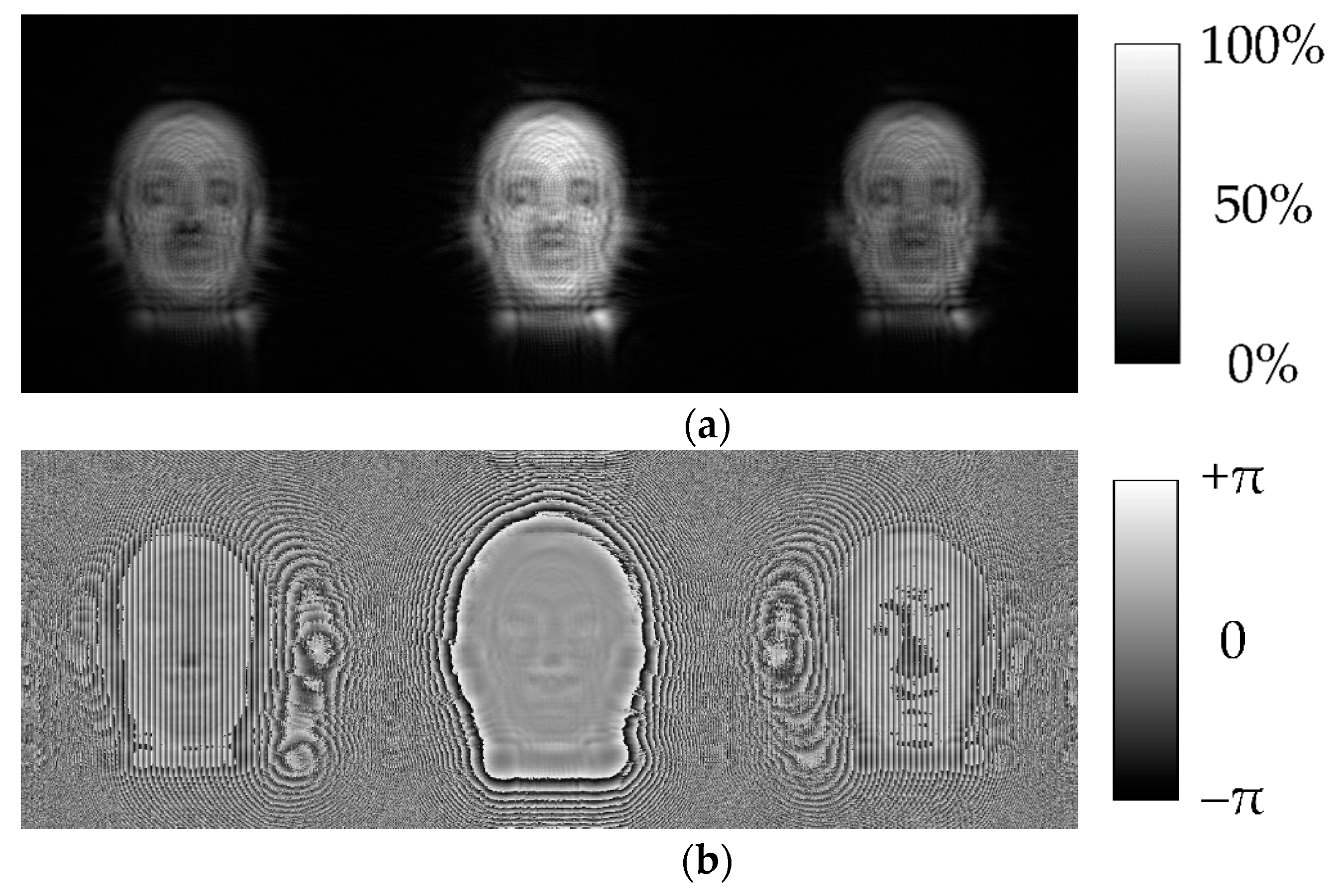
The results obtained in the calculation of the Fresnel transform from the hologram (
Figure 3) are shown in
Figure 5a,b. Here,
Figure 5a corresponds to the amplitude component of the Fresnel transform, while
Figure 5b corresponds to the phase component. The observation distance of Fresnel diffraction was chosen to provide reliable spatial separation between all three diffraction orders as shown in
Figure 1.
The results of similar calculations from the structured light fringe pattern (
Figure 4) are presented in
Figure 6a,b where
Figure 6a corresponds to the amplitude component of the Fresnel transform, while
Figure 6b corresponds to the phase component.
One can see that the diffraction patterns at the array of structured fringes (
Figure 6) and the hologram (
Figure 5) are very similar to each other. A more detailed investigation of the structure of the obtained holograms under substantial magnification confirms this similarity.
5. Image Restoration
Calculation of the inverse Fresnel transformation from the minus first diffraction order (
Figure 5, right) gains the amplitude and phase of the 3D object recorded previously in the hologram of focused images (
Figure 7).
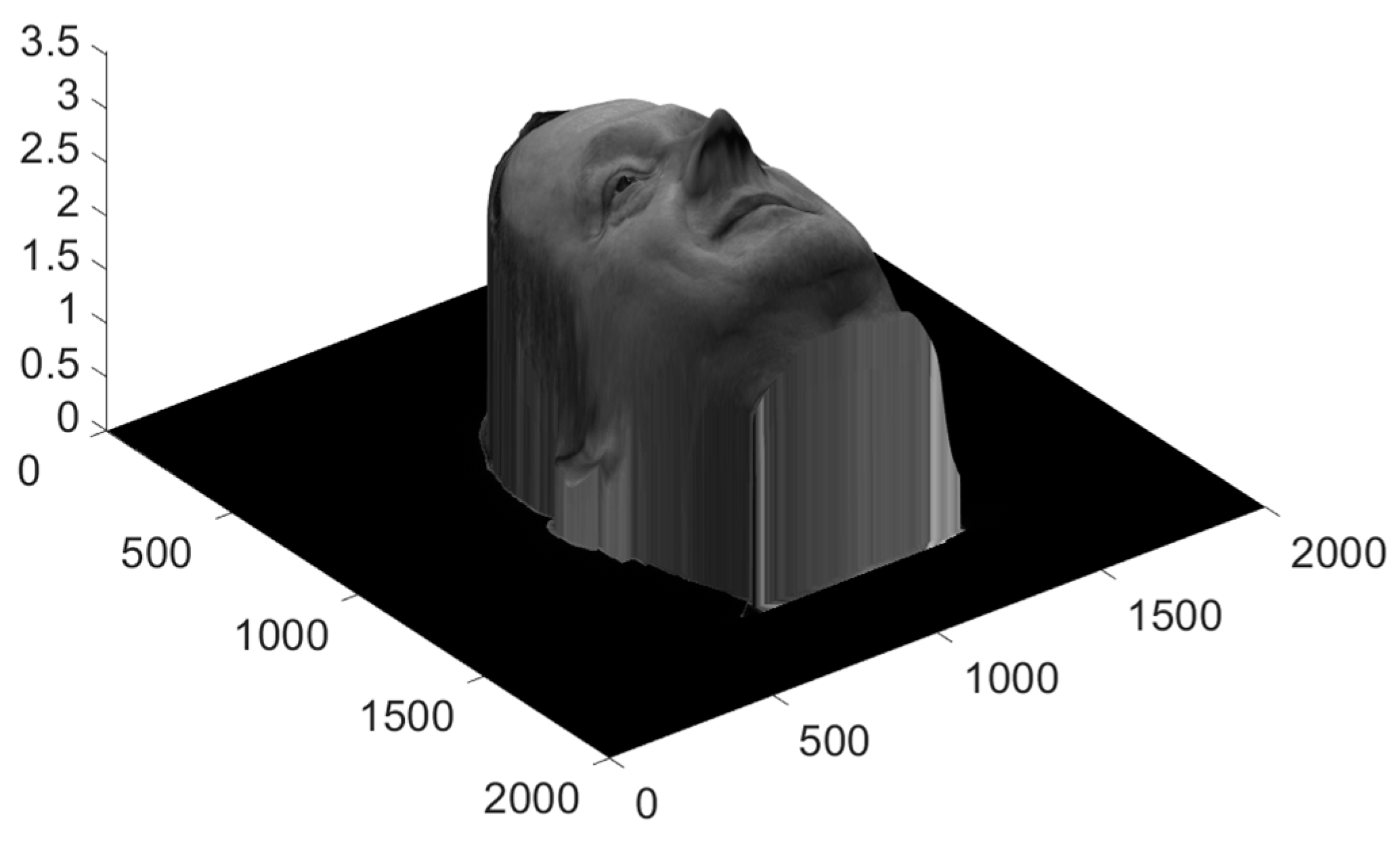
Collected together, after multiplying the depth by compression factor 1/Ҟ fixed previously, they form the 3D object restored by the computer hologram (
Figure 8).
Calculation of the inverse Fresnel transform from the similarly selected part of SLFP (
Figure 6, right) allows us to obtain the amplitude and phase of the 3D object restored through diffraction at SLFP (
Figure 9).
Collected together, after multiplying the depth by compression factor 1/Ҟ fixed previously, they also produce the 3D object shown in
Figure 10.
Comparing two 3D images obtained by diffraction at SLFP (
Figure 10) and by diffraction, at the hologram of focused images (
Figure 8) one can see their essential similarity, which allows us to state that the array of vertically structured fringes possesses all major properties of a hologram—during irradiation with the coherent reference wave, it restores the 3D image of the object with the continuous horizontal and vertical parallax.
The difference between the depth maps of the object obtained from the hologram (
Figure 7b) and the structured fringe pattern (
Figure 9b) is illustrated in
Figure 11.
The differences between the restored depths turned out to be within ±5%, which is a good result. This is more obvious in the illustration shoring the combined profiles (
Figure 12).
6. Discussion of Results
In
Figure 12a, one can see almost completely coinciding profiles shifted with respect to each other in the vertical direction artificially to provide a convenient comparison, while the profiles are combined in
Figure 12b. One can see that the profiles almost coincide with each other. Small deviations may be caused by the inaccurate fixation of distortions of the structured light patterns. Their manifestation in the form of distortion of the restored wavefront is close in essence to the field aberrations of cushion-type distortion, which distorts the geometric dimensions of the image but does not determine the resolution.
This is quite clear because the oblique projection of the vertically structured fringes falling on the 3D object (
Figure 13a) produces their shift in the plane perpendicular to the optical axis of the photo recording device, similar to the shift of interference fringes during the recording of the hologram (
Figure 13b).
Comparing
Figure 13a,b one can see a principal similarity between the mechanisms of distortion of the interference and structured fringes, which points to the fact that diffraction at structured fringes forms the 3D images of the initial object restored in minus first order, close in shape to the images restored by computer holograms. In the initial form, these patterns of structured fringes are usually close to the holograms of the radio range, which is determined by their frequency in the initial pattern of the project onto the object. However, their frequency may be increased by simple linear transformations without resource-intensive integration, leading to a frequency that is equivalent to the carrier frequency within any wavelength range including visible, infrared (IR), ultraviolet (UV), etc. The pattern of structured fringes shown in
Figure 2c, before transformation that increases the carrier frequency (
Figure 4b), may be considered as the diffraction structure operating as a hologram synthesized in the radio range of the electromagnetic spectrum.
Comparing the obtained 3D images in
Figure 8 and
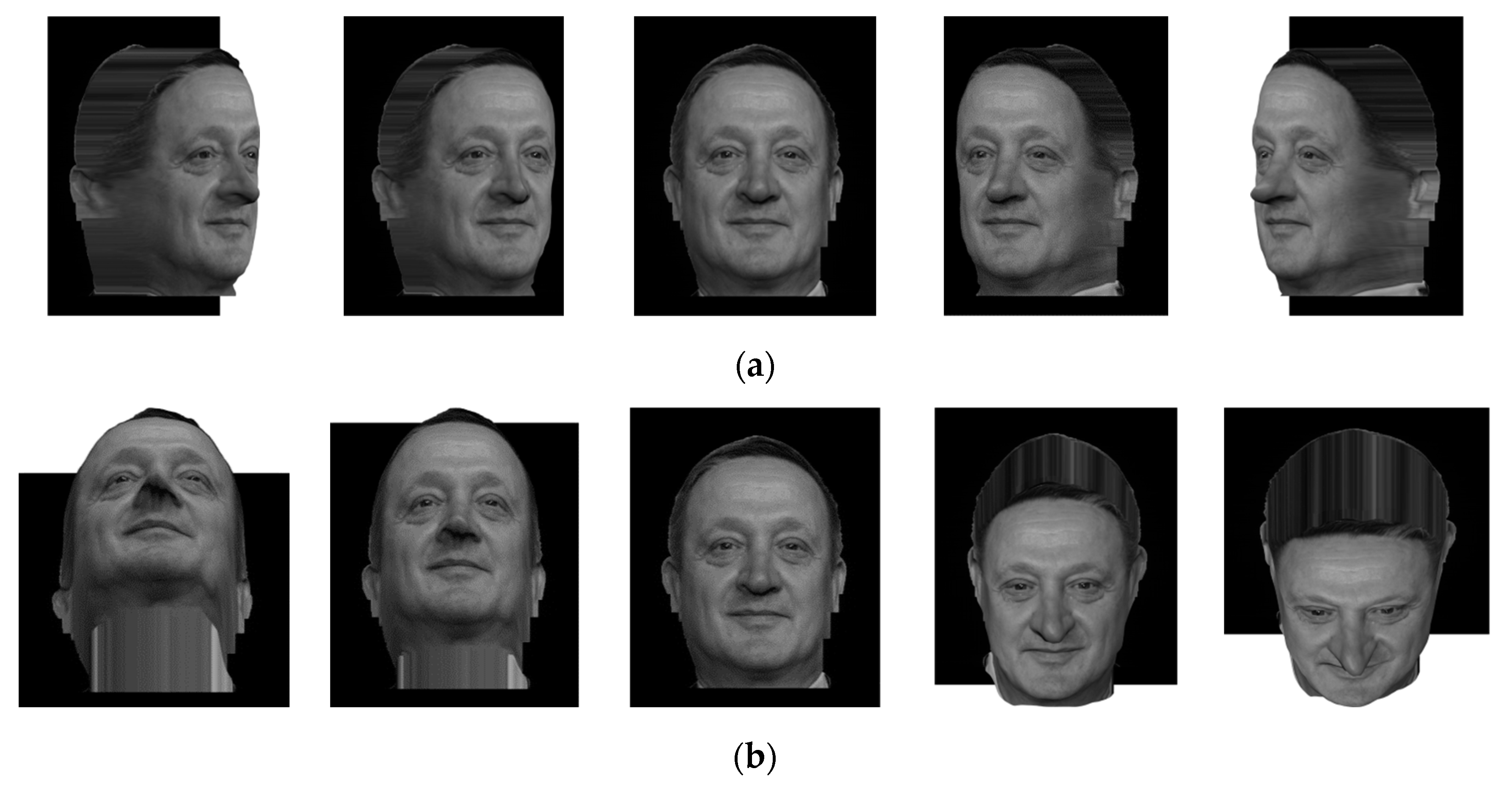
Figure 10, one may see that the hologram and the system of structured fringes restore very similar, full-value 3D images. Their iso-projections demonstrating evident similarity are presented in
Figure 14 and
Figure 15.
The image restored by the hologram and the image restored by the system of structured fringes possess both the horizontal and vertical quasi-continuous parallax, so they are full-value holograms. We use the term ‘quasi-continuous’ only in relation to the digital representation of the signal. The degree of parallax continuity is limited only by its digital representation and may be reduced to the desired minimum by increasing the array of numerical representations of the holographed object and the hologram. A small difference between the two restored 3D images of the living object is seen in the top part of the depth map of the object. In our case, this is the region of the nose of the 3D image. This is likely a consequence of the arising longitudinal aberrations, which will be the subject of a more detailed investigation.
Attention should be paid to the non-trivial fact that the system of lateral vertical fringes illuminating a 3D object forms a structure that has information not only about the horizontal but also about the vertical parallax, almost the same as a hologram calculated in parallel in the traditional way. Therefore, the method of formation of the 3D object hologram chosen by us previously may be simplified substantially, which is extremely important for the acceleration of transmission [
27,
28,
29] and computer processing of the series of frames of 3D video and augmented reality.
The use of the above-obtained result is proposed in order to reduce the amount of transmitted information even in comparison with that proposed in [
7], however, remaining sufficient for forming the holographic video sequence at the receiving end of the radio communication channel. For this purpose, it is proposed that one should transmit, instead of two 2D frames (depth and texture maps), only one 2D frame but have it enlarged somewhat by twenty-five columns. For instance, for the Full HD standard, this will be not the 1920 × 1080 frame but a 1945 × 1080 frame, in which the additional 25 columns will carry the information on the structured light pattern in the form of vertical fringes that were illuminating the holographed object (
Figure 2c). At the receiving end of the communication channel, these 25 columns will be used to create a diffraction structure similar to that shown in
Figure 4a, restoring the 3D image of the depth map (
Figure 9b). Superposition of the texture frame on this diffraction structure allows restoration of the 3D image of the object as a total, as shown in
Figure 10. It should be stressed that the latter will work efficiently only in the case of a rather short Rayleigh distance, while diffraction has not yet blurred up the texture image. This condition is known to be fulfilled if the number of Fresnel zones fitting into the hologram field is much larger than unity. This condition is actually in the holograms of focused images when the 3D image is brought ahead of the hologram at the space depth not more than several diagonals of the holographic monitor or the hologram.
7. Transmission of 3D Holographic Information along the Radio Channel
As mentioned in the Introduction, the transmission of holographic information along communication channels involves the problem connected with the high capacity of holograms. The possibility of efficient compression of holographic information, similar to the transmission at one sideband known in radio electronics, was demonstrated in patent RU 2707582 C1 [
7]. In this situation, as shown in [
14], this compression is already sufficient for the transmission of 3D holographic information along the radio communication channel. It is even more so if, as described above, the transmission of one of the two components of 3D image basic modalities (depth maps of the holographed 3D object) is replaced by the structured light pattern formed by photo capture of the lateral projection of straight fringes on the 3D object. Indeed, in this case, the load on the communication channel and computational resources at the receiving end decreases more substantially. Along with the texture of the 3D object surface, not two 2D frames but only one is transmitted, though it will be somewhat wider than that in the conventional standard, or two 2D frames but with the second one possessing an order of magnitude lower resolution than the first one in the plane perpendicular to the initial direction of structured light fringes. In fact, even the necessity to form the second frame disappears. All its information is fitted into a small additive to the first frame with the texture, similar to the case of analog TV frame encoding when each scanned line ends with the operation information concerning line or frame change. However, in our case, the amount of operation information is larger, and this is more like the wide-screen frame format. As described above, diffraction at the structured fringe pattern forms a 3D image of the depth map of the holographed object. The experimental transmission of this compressed information along a wireless Wi-Fi communication channel, with a frequency bandwidth of 40 MHz, and a frame rate of more than 25 frames per second has been described in the conference proceedings [
27]. Developing the obtained result, we repeated the experiment on the transmission of holographic information of 3D images along a wireless Wi-Fi communication channel for 3D video transmission with the help of the FTP protocol. In this case, each transmitted frame of the 3D image was one 2D frame—texture (2000 × 2000 pixels) and the pattern of structured fringes (25 × 2000 pixels) (
Figure 16).
To imitate the transmission of a video sequence, the packets containing 291 such frames were transmitted simultaneously. The time of packet transmission, measured by the FileZilla software, during real-time representation shows that the transmission of the complete holographic information about a dynamic 3D object is quite implementable both for the frame standard similar to HD and for the Full HD.
In the experiment on the transmission of holographic 3D video, the transmitted 2D frames composed of the texture and the operation information were formed with different compression degrees.
All frames were preliminarily prepared in the following formats: BMP (without compression), PNG (compression without losses), and JPEG (compression with losses, 70% quality). Experiments were carried out for each of the listed formats.
The sizes of frames with texture and mask were chosen in the following combinations:
500 × 500 pix. texture + 25 × 500 pix. structured fringe pattern;
1000 × 1000 pix. texture + 25 × 1000 pix. structured fringe pattern;
2000 × 2000 pix. texture + 25 × 2000 pix. structured fringe pattern.
For convenient test transmission, all frame sets were packed into uncompressed ZIP archives.
Results of the measurement of packet transmission time were processed and are shown in
Table 1.
The first column of the Table indicates the running number of an experiment with test transmission of the holographic 3D information. The column entitled “Resolution, pix.” shows the resolution of frames with texture image (T) and mask (M), respectively. The column entitled «Frame format» indicates the formats of files into which the initial image arrays were compressed. The number of frames transmitted in a packet is shown in the column entitled “Number of frames”. The column entitled «Packet volume, MB» represents the volume, in MB, of the transmitted packet with frames, where indices T and M mark the volumes of a frame with texture and a frame with mask separately. The column entitled “Communication channel capacity” shows the transmission capacity of the Wi-Fi communication channel used, in MB/s. The column “Transmission frame rate” lists the frequency of frames transmission, determined on the basis of the measured rate of data transmission along the Wi-Fi communication channel, in frames/s.
One can see that the frame rate turned out to be more than 25 frames per second in experiments Nos. 1–3, 5–6, and 8–9 (rows in the table are highlighted in green). This means that it is possible to transmit the 3D holographic information in PNG and JPEG formats both for the TV standard similar to SECAM and for HD and Full HD. The BMP format is unsuitable for frame transmission in our case for the resolution higher than that involved in Experiment No. 1, because of the absence of any conventional type of compression of the transmitted 2D frames, and, as a consequence, too bulky files with the frames to be transmitted. Nevertheless, the BMP format is quite suitable in the proposed technology for use in the systems of holographic phototelegraphy, as one can see in the results of experiments in rows 4 and 7.
The versions of 3D data transmission shown in
Table 1 may be applied in various 3D augmented-reality facilities, in particular, in telemedicine, in the systems of remote control of complicated objects, including safety systems, 3D phototelegraphy, etc.
