1. Introduction
Additive manufacturing technology is a process that uses a discrete-stacking approach to stack materials layer by layer to eventually form a three-dimensional solid [
1,
2]. It can generate parts directly from 3D solid models without process planning, which can greatly reduce the difficulty of machining complex parts. Additive manufacturing technology has many advantages; firstly, it can manufacture extremely complex parts that are difficult to produce by traditional processing methods. Secondly, it saves materials, and some materials of additive manufacturing technology can be recycled multiple times, etc. Because of its advantages, additive manufacturing technology is now being used in the medical, aerospace, automotive, food, and engineering industries. For example, the medical industry has started to experiment with the use of 3D printing technology to develop tissues, organs, and cellular structures [
3,
4]. The use of 3D printing in the automotive industry has reduced the time required to process molds and reduced the cost of manufacturing prototypes [
5,
6]. The aerospace industry has used 3D printing to reduce fuel consumption and material waste by lightweight traditional structures or replacing them with new geometries that are structurally complex but more practical [
7,
8].
Additive manufacturing technologies include photopolymer molding technology, selective laser sintering, 3D printing technology, and fused deposition manufacturing [
9]. Among them, FFF is the simplest and most commonly used technique in additive manufacturing technology, which has simple equipment and is easy to use. In this paper, we choose the FFF 3D printing technique, which prints pre-prepared fiber filaments through a nozzle [
10]. After passing through a nozzle with a heated section, the filament is driven by the nozzle to lay the filament in a pre-set path, and the layers are stacked to finally obtain the required prototype part. The choice of filament material depends on the application and the desired properties. Today, commonly used materials include polylactic acid (PLA), PETG, HIPS, and ABS. Among them, PLA is widely used for printing in FFF technology due to its good mechanical properties and printing performance. However, the tensile properties and strength of pure PLA are not enough, and in order to improve the strength most of the current methods are to add nanofibers, [
11] short fibers [
12,
13], or continuous fibers [
14] to it. There are many researches on the printing process parameters of FDM matrix printing and short fiber reinforced composite printing. Kantaros Antreas et al. [
15] studied the pure matrix FFF printing process parameters, and they believed that layer height, infill percentage, printing speed, shell thickness, printing temperature, retraction, and supports existence have immense contribution towards achieving desired printing results, and the range of setting process parameters is proposed. Altan et al. [
16] investigated the effect of process parameters on the surface roughness and tensile strength of PLA samples. The samples were made according to ASTM standards and the Taguchi L16 experimental design. The results showed that the print layer thickness and print head speed were the main factors affecting the surface roughness. Mercedes Pérez et al. [
17] analyzed the effect of print parameters on the sample quality using statistical and graphical methods and performed an analysis of variance (ANOVA). It can be seen that the layer height and wall thickness are the factors that affect the surface roughness. The layer height was the most significant. For a wall thickness of 1 mm, a layer height of 0.15 mm resulted in the lowest surface roughness. Ala’aldin Alafaghani et al. [
18] investigated the main effects of printing parameters on dimensional accuracy, dimensional repeatability, and mechanical properties in the FFF process using Taguchi’s DOE. It was found that maximum strength and Young’s modulus can be obtained when choosing 210 °C printing temperature, 0.30 mm layer thickness, triangular filling pattern, and 100% filling. To reduce dimensional errors, 190 °C printing temperature, 0.20 mm layer thickness, hexagonal fill pattern, and 20% fill percentage can be selected as printing parameters. Arit Das et al. [
19] used the DOE method to evaluate the effects of layer thickness, raster angle, and infill pattern on the tensile properties of PA6 parts reinforced with short CF processed using FFF. They found that the layer thickness and print pattern have a profound impact on the maximum tensile strength and tensile modulus.
For discontinuous fiber-reinforced composites, it is still the matrix material that dominates the mechanical properties, and adding natural fibers even reduces the tensile and flexural strength of the composite. Compared with short fiber-reinforced composites, the tensile and flexural strengths of continuous fiber-reinforced composites can be seven and five times higher, respectively.
A large number of studies have been published to demonstrate that adding continuous fibers to a pure matrix material can substantially improve the mechanical properties of the material, but it is still not as good as the mechanical properties of parts produced using traditional processing methods. To further improve the mechanical properties of continuous fiber-reinforced composite parts, some scholars have optimized the process parameters; some scholars have changed the printing method; and some scholars have applied pressure to the printed parts during printing. All these methods can improve the mechanical properties of the printed parts.
For the study of improving mechanical properties by optimizing printing parameters, Tian et al. [
20] developed their own co-extrusion printer to find out the appropriate process parameters for printing continuous carbon fiber-reinforced PLA. The printing temperature was 200–230 °C, the recommended layer thickness was 0.4 to 0.6 mm, etc. The flexural strength of the printed composite specimens was 335 MPa, and the modulus was 30 GPa when the fiber content reached 27%. Dong et al. [
21] used continuous Kevlar fiber-reinforced nylon material for FFF printing and investigated different process parameters such as fiber orientation, number of fiber layers, fiber position, and nylon raster angle. The results showed that the modulus of elasticity of continuous fiber-reinforced nylon could reach 27 GPa, and the strength was 333 MPa, and the mechanical properties of continuous fibers were improved much more than those of short fibers.
Andrew N. Dickson et al. [
22] used a Markforged Mark One 3D printer to print continuous carbon fiber, continuous aramid fiber, and continuous glass fiber-reinforced nylon composites, respectively, to investigate the effects of fiber orientation, fiber type, and volume fraction on mechanical properties. Tensile and bending experiments were also performed. The results showed that, among the studied fibers, the specimens made using carbon fibers showed the largest increase in mechanical strength per unit fiber volume. Their tensile strength values were 6.3 times higher than those using non-reinforced nylon polymers. As the volume content of carbon and glass fibers increases, the amount of air entrapment in the composite matrix also increases, which affects the mechanical properties. The maximum tensile strength was observed in glass specimens when the fiber content was close to 22.5%. Ali Bin Naveed et al. [
23] used Kevlar fibers as reinforcing fibers for ABS, PLA, PLA- c, and PLA- cu thermoplastic materials with Taguchi orthogonal tests followed by tensile and flexural tests, which increased the tensile strength up to 3 times and flexural strength up to 1.6 times compared to the pure matrix material. Yesong Wang et al. [
24] used continuous glass fiber-reinforced PLA and investigated the effects of process parameters such as printing temperature, speed, layer height, and fiber volume fraction. The mechanical properties were explored using tensile and three-point bending tests. The experimental results showed that the mechanical properties of continuous glass fiber-reinforced PLA were better than those of pure PLA. When the fiber volume fraction was about 5.21% and 6.24%, the tensile and flexural strengths of the specimens were increased by 400% and 204%, respectively.
In order to improve the quality of FFF parts, many research works have been carried out by researchers in the last decade. It has been confirmed that process parameters do have a significant impact on the quality of the manufactured product. However, there are many process parameters of FFF that affect the mechanical properties and dimensional accuracy of a part. In order to fully understand the influence of various processing parameters on the parts printed by using FFF technology, it is essential to select a suitable experimental design and analysis method to take full advantage of all parameter combinations, besides an extensive analysis process. In the past, there has been a lot of research on the effect of printing parameters on the surface roughness, dimensional accuracy, and mechanical properties of parts printed using FFF. Commonly used DOE significant experimental methods that can optimize process parameters are the Taguchi method [
13,
15,
25] full factorial design [
26,
27], analysis of variance [
28], bacterial forging techniques [
29], and fuzzy logic [
30].
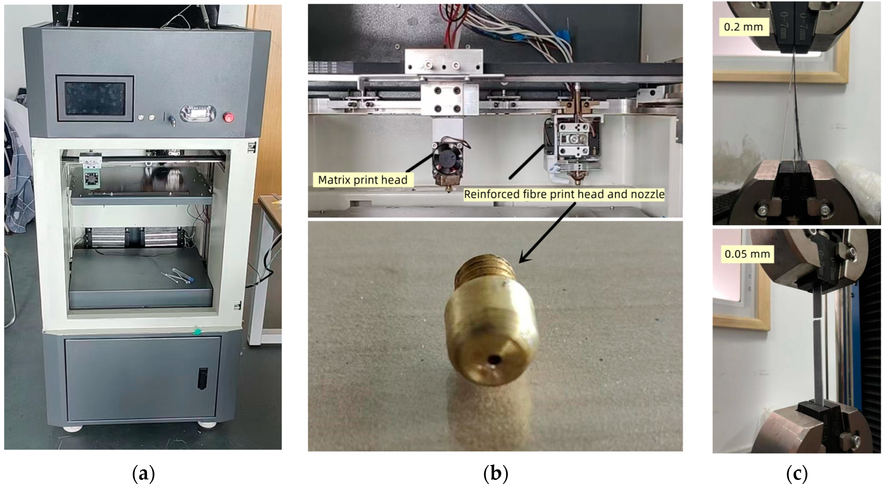
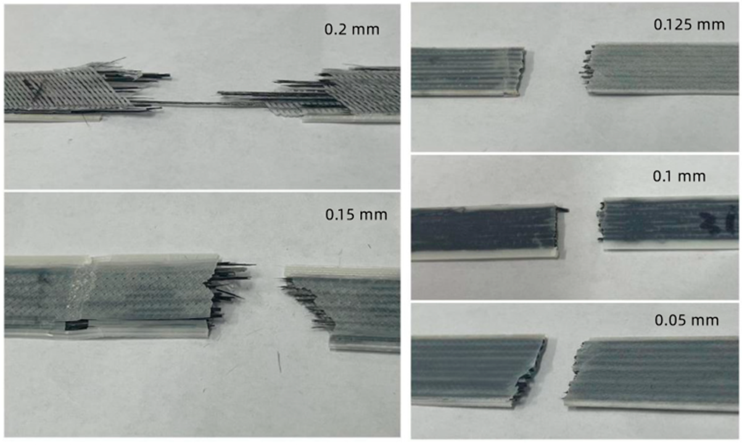
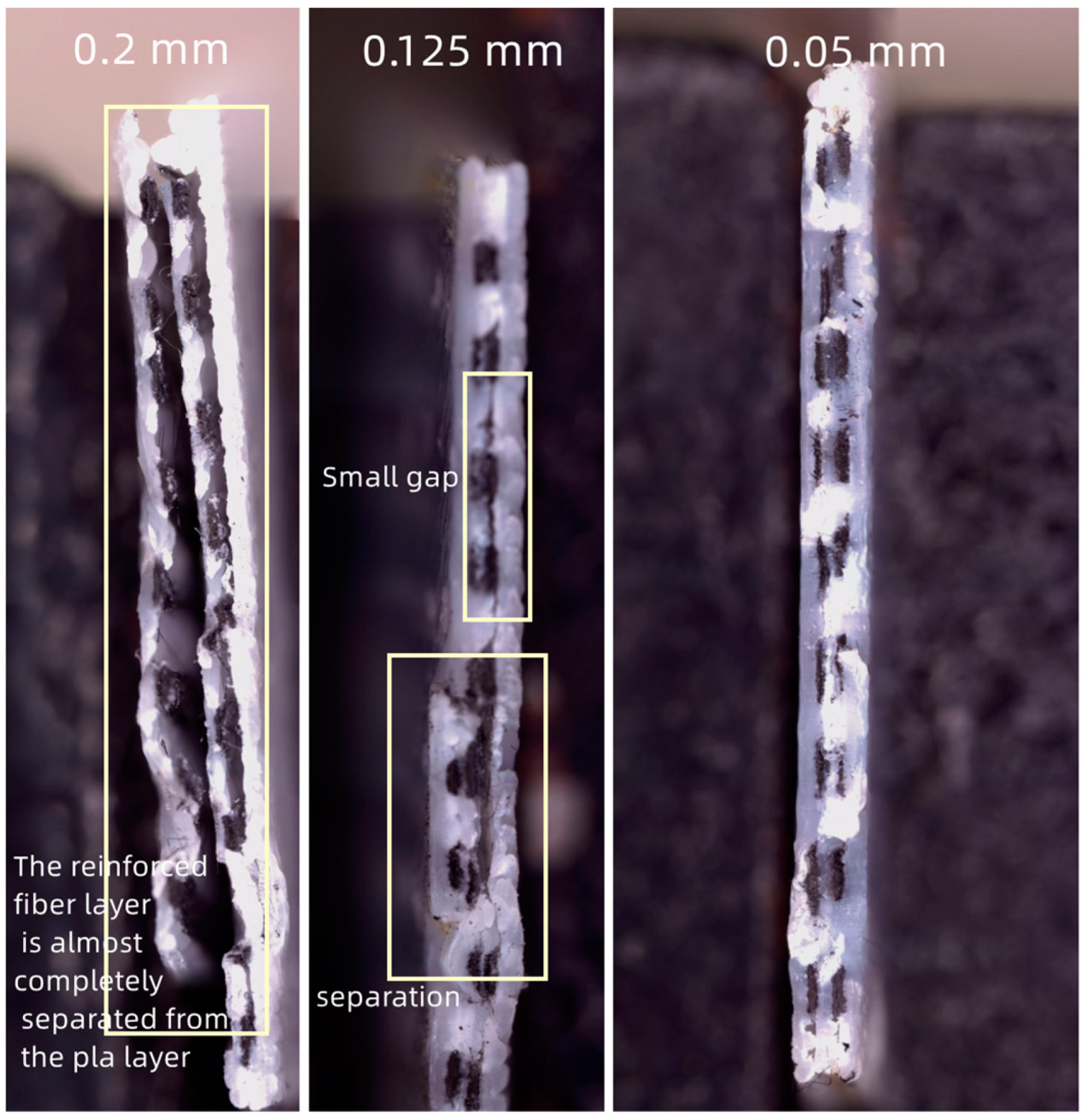
In this paper, an independent extrusion type 3D printer is selected. The Taguchi method was used to scientifically select the factors investigated, and then full factorial analysis was used to investigate the ultimate printing parameters of three factors: fiber printing temperature, fiber printing layer thickness, and fiber printing speed, as well as the effects of their interactions on the strength of the printed parts. The findings were verified again in supplementary tests, and the effect of fiber overlap was excluded. Finally, the interfacial morphology of printed parts with different layer thicknesses was investigated using ultra-deep field microscopy and specimen fracture forms.
2. Experimental Method
2.1. Taguchi Method
The Taguchi method is a low-cost, high-efficiency quality engineering method that emphasizes that product quality is improved not through inspection but through design. In the product design process, the Taguchi method uses the functional relationship of quality, cost, and benefit to develop high-quality products at low cost.
In this study, the modified Taguchi method of Xuesong Jiang was used [
31]. The evaluation method of fuzzy set theory and correlation matrix was combined to establish a factor selection model for the selection of Taguchi method factors. The three evaluation indicators of severity (
S), detection degree (
D), and controllability (
C) of the factors were considered comprehensively, and the corresponding fuzzy linguistic term sets established by Xuesong Jiang were referred to. Finally, they are quantified using fuzzy numbers, which are determined based on the recommendations of published articles in the field and the experience of practical experiments. The fuzzy language term description level is divided into five levels, and the corresponding fuzzy numbers are from 1 to 5 points, respectively. The language terminology is shown in
Table 1.
The formula for assessing the importance of an impact factor
Xi by using the correlation matrix method is as follows:
In the equation, Xi (i = 1, 2, …, n) represents the impact factor to be evaluated. WS, WD, and WC represent the weights of severity (S), detection (D), and controllability (C). Vij represents the fuzzy number of each dimension under different impact factors, (i = 1, 2, …, n; j is severity, detection, and controllability). Vi represents the combined assessment value of the impact factor Xi under the three dimensions of severity (S), detection (D), and controllability (C). The higher the value of Vi, the higher the importance of the factor.
The factors of the research were first selected by using the Taguchi method. Where the fuzzy number was determined based on the recommendations of published articles in the field and the experience of the actual experiments. The specific scores obtained by referring to the language terminology table for different print parameters are shown in
Table 2.
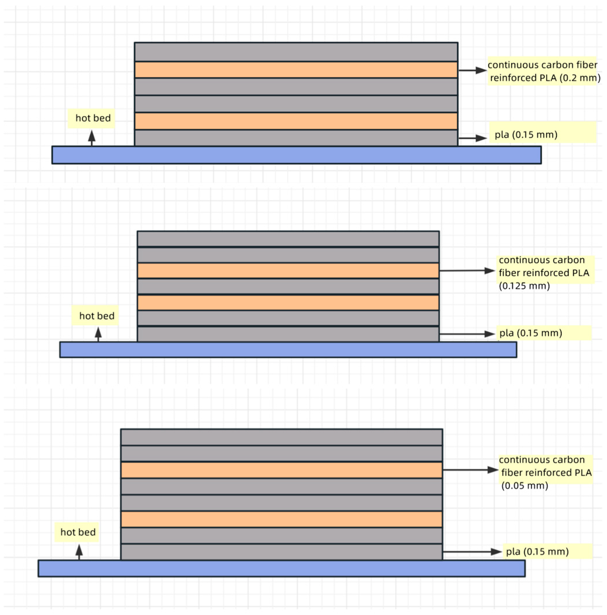
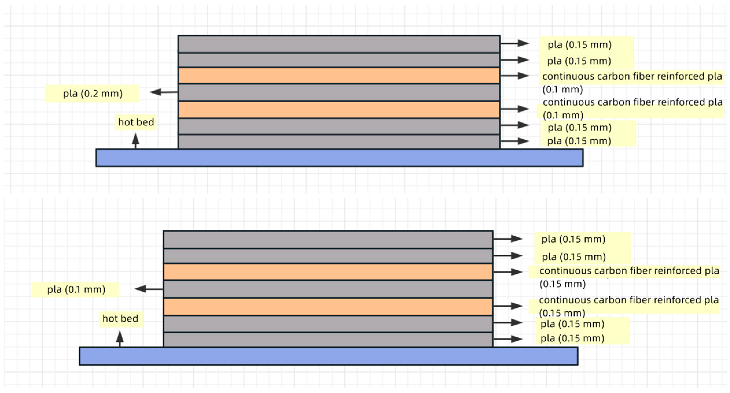
According to the influence factor assessment correlation matrix table, combined with the purpose of this paper, the printing temperature, layer thickness, and printing speed of the reinforced fiber were selected as the study process parameters. Initially selected parameter ranges are reinforced fiber print temperature 190–230 °C, reinforced fiber print layer thickness 0.2–0.4 mm, and reinforced fiber print speed 120–400 mm/min.
2.2. DOE Full Factorial Test
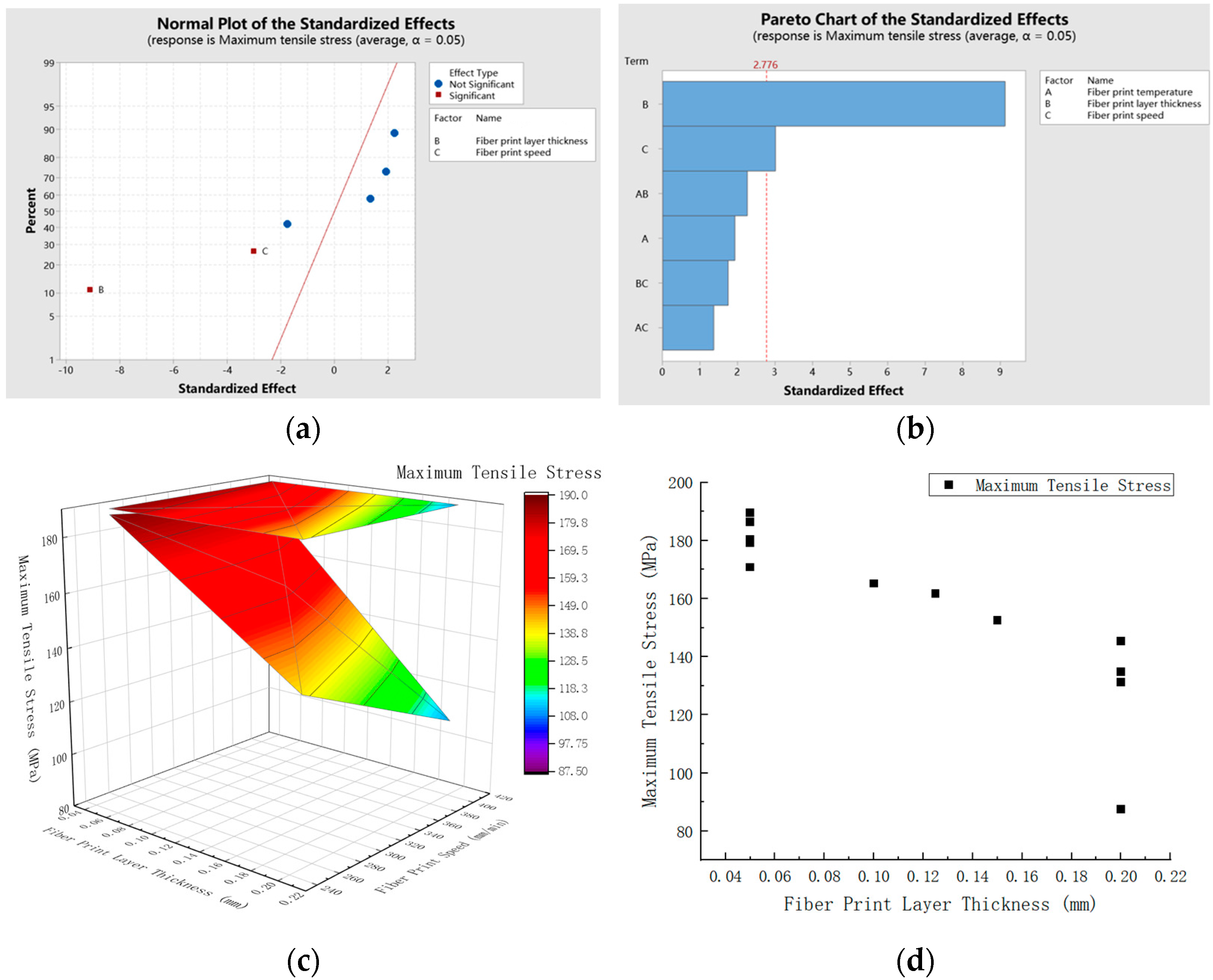
The effect of interactions was not considered in the Taguchi method orthogonal test analysis. However, considering that there may be interactions between the printing parameters, the DOE full factorial orthogonal experimental analysis was used in the subsequent. A full factorial experimental design is defined as a design in which all combinations of all levels of all factors are tested at least once. However, when the number of factors is higher than 2, the number of trials increases at an exponential rate with the number of factors. Thus, only full factorial tests at level 2 are commonly used. In engineering or experiments, it is usually considered that a two-level test design with the addition of center points can replace a three-level test in a considerable extent. Also, the analysis is simple and easy to conduct. Usually, if the curve is bent after the orthogonal analysis, additional climbing experiments or response surface methods are used to obtain more detailed and comprehensive results.


